
Nonlinear Transient Modeling and Design of Turbocharger Rotor/Semi-Floating Bush Bearing System

Rotor Bearing Solutions International, Charlottesville, VA 22903, USA
*
Author to whom correspondence should be addressed.
Lubricants 2017, 5(2), 16; https://doi.org/10.3390/lubricants5020016
Submission received: 2 May 2017
/
Revised: 29 May 2017
/
Accepted: 6 June 2017
/
Published: 12 June 2017
(This article belongs to the Special Issue Bearings in Turbomachinery)
Abstract
:This work presents the bearing design and analysis of radial semi-floating bush oil lubricated bearings for a typical industrial turbocharger configuration. Initially, the stability analysis for a linear rotor/bearing system is evaluated through eigenvalues and eigenvectors. The stiffness and damping coefficients of the inner oil film are obtained for the linear modeling process. The operating speed range of the turbocharger is high enough, at 21,000 to 24,000 rpm, to be unstable, indicating that the analysis should be and is carried out with nonlinear transient modeling. The nonlinear transient analysis evaluates the rotor and bush limit cycle orbits, rotor dynamics, the forces acting on the rotor and semi-floating bush surfaces, the oil flow through the bearing, the oil temperatures, and the power loss of the two oil films. The optimum design of a set of semi-floating bush bearings for this application depends strongly upon the clearances of the bush and squeeze film damper, usually expressed as the non-dimensional clearance to radius ratio. A typical clearance is evaluated to determine the bearing performance in terms of orbit size, forces acting on the bush and squeeze damper surfaces, oil flow through the bearing, power loss, and thermal heating. The nonlinear transient orbit values are evaluated for frequency content using the FFT to determine which orbits show both the synchronous and sub-synchronous vibration components and the associated rotor modes excited. These results are compared to the linear analysis over the operating speed range. The oil flow through the bearing component is much larger than the squeeze film damper. The forces acting on the bush and squeeze damper surfaces are related to the fatigue life of the bearing.
1. Introduction
Turbochargers are commonly supported in fluid film bearings of several types: (1) single oil film bearings; (2) two oil film, fully floating bush bearings; (3) ball bearings supported by squeeze film damper; and (4) two oil film, semi-floating bush bearings (squeeze film damper supported fixed-pad bearings). Typically, small automotive turbochargers are constructed of one of the first three types using fixed-pad bearings, due to cost considerations. All of these bearings usually operate at very high rotating speeds and are commonly linearly unstable. In this context, the term instability means that rotor vibration orbits take up a relatively large fraction of the bearing clearance and have sub-synchronous vibration components in addition to synchronous components. Ball bearings are very limitedly used in turbochargers due to lack of damping characteristics.
Fully floating ring bearings (FRBs) are the commonly employed type in the small turbocharger designs used mainly in automotive applications. In these turbochargers, the running speed reaches to well above 100 krpm and FRBs reduce the parasitic power loss as a rotating ring (bush) in their design separates the supporting lubricating films into inner and outer oil films. The bush in the middle is free to rotate due to the shear drag of the inner film. Numerous papers are dedicated to these types of bearings [1,2,3,4,5,6,7,8]. A thorough rotordynamic investigation was conducted by Gunter and Chen [1], which identified three unstable modes in the operation range of turbocharger with floating ring bearing. They showed large amplitude limit cycle vibrations in the bearings using a nonlinear time transient analysis. They examined running the bearing with locked ring and concluded a worse operation condition for the bearing that reduces the turbocharger life. Opening the inner and outer clearances in the bearings resulted in a shift from translational motion to conical motion of the turbocharger shaft [1]. Schweizer [2], in an interesting study, investigated the dynamic operation of turbochargers supported with FRBs via bifurcation theory. In this paper, the linear instability of the bearing at an equilibrium point is extended to study the bifurcations of sub-synchronous vibrations in a limit cycle in the run-up and run-down. He showed that different limit cycles may lose stability and bifurcate to a different limit cycle with different amplitudes. He identified the very large amplitude limit cycle vibrations as “total instability” which often results in the turbocharger destruction [2]. To avoid the total instability (or critical limit cycles), Tian et al. [3] examined the effect of outer clearance of the FRB as a controlling design parameter by changing which the critical limit cycle oscillations are removed. They also investigated the operation of floating ring bearings with external excitations transmitted from the engine [4]. San Andres et al. [5] explored thermohydrodynamic behavior of floating bush bearings used in small turbochargers and showed that they exhibit large amplitude sub-synchronous vibrations in a large range of speeds. These bearings are inherently unstable and operate at limit cycles. FRBs experience intense thermal effects in viscosity change of the lubricant, and structural growth of bush and shaft. This makes them prone to bush/ring locking at high speeds which increases the power consumption by removing the effectiveness of the ring in the bearing system and reducing it to a single fixed-pad journal bearing.
Despite the popularity of floating ring bearings in small size turbochargers, they are neither reliable and applicable nor required in large, heavy, lower speed turbochargers in locomotive and diesel engines to reduce large parasitic power loss due to high speeds [6,7,8]. In these turbochargers semi-floating bearings are more commonly used which constitute basically of a fixed-pad journal bearing supported with a non-rotating ring, i.e., a squeeze film damper. These bearings are very limitedly researched, unlike their full floating counter parts. Chen [6] discussed the industrial turbocharger bearings applications: small/fast turbochargers in automotive and aerospace fields, and large/slow application in locomotive and marine fields. Fixed-pad multi-lobe bearings with and without preload are discussed by him, as well as squeeze film damper supports, which are the commonly used bearings in large turbochargers. He also examined the stability of the semi-floating bearings as well as full-floating ones and concluded that they both share in the unstable limit cycle operation [6]. Kelly [7] studied the dynamic characteristics of a commercial diesel engine turbocharger. Three different types of bearings including full-floating bearing, semi-floating bearing, and ball bearing with squeeze film damper are studies, and the analytical results were compared with the experimental data [7]. Typically, the operating speed range of the automotive turbocharger is above the first two rigid modes and may be above the third mode (1st bending mode). The structure and two wheels at each shaft end makes the rotor an overhung rotor and the rotor mass center of the assembled large turbochargers is typically near the center of the bearing span, which have considerably different vibrating mode shapes from the smaller turbochargers [7]. Shi and Deng [8] compared full-floating and semi-floating bearings used in turbochargers and found that a full-floating bearing has lower power losses than a semi-floating bearing. Typically, the power loss reduction of full-floating bearings range is from 13% to 27%. Compared to semi-floating bearings, however, full-floating bearings often have a smaller minimum film thickness under a certain dynamic load [8]. Cao and Dimond [9] studied reduction of vibration and power loss in industrial turbochargers. Three different types of bearings are compared: fixed-pad bearing, tilt-pad bearing, and pressure dam bearing. Of three bearings, tilt-pad bearing gives a stable system and if starved oil supply is chosen, power loss can be reduced by 50% compared to fixed-pad bearing. The cost of tilt-pad bearing limits the application to the larger turbochargers [9]. There is a very limited design and analysis literature of larger, industrial turbochargers with semi-floating bearings.
A preliminary study of a reciprocating machine is considered, as shown in Figure 1. The baseline bearing for this application is a four-pad fixed-pad with load-on-pad configuration. The original turbocharger configuration was found to be highly unstable. Two candidate replacement bearings are considered to reduce vibration levels, force levels and power loss. The first configuration is a five-pad fixed-pad inner film bearing and the second configuration has the same inner film bearing and a squeeze film damper (semi-floating) outer film bearing.
2. Analysis Method
The rotordynamic analysis of the turbocharger was performed in the following steps. First step is a steady state based linear stability analysis to evaluate the stability of the system. In this step, the bearing coefficients from bearing steady analysis were used. The goal of this step was to show that the system stability decreases with shaft rotating speed increasing and the rotor is unstable under operational running speed. A nonlinear time transient analysis of the rotor supported only by the fixed-pad bearing was then applied. The bearing power loss was calculated based on the limit cycle orbits. It would show that the shaft orbit is so large that linear analysis is not accurate anymore. Introducing squeeze film damper into the system or using semi-float bearing to estimate system behavior is the third step.
3. Model of Turbocharger Rotor
The turbocharger rotor bean model is shown in Figure 2. A total of 16 Timoshenko beam elements are used with a compressor wheel at one end and a turbine wheel at the other end. The compressor impeller, which C.G. has offset (as shown in Figure 1), is located at node 6, and the turbine impeller is located at node 16 (node 1 is the left end). The two wheels are modeled as lumped mass. This is a double-overhung rotor with the compressor-end bearing at node 11 and the turbine end bearing at node 14. The compressor seal is on the opposite side of the eye of the compressor impeller and was placed at node 7. In the model, green spots indicated the nodal location of wheels and bearings, those noses are the output nodes for transient analysis too. The axial force effect for those nodes inside the compressor impeller is considered by adding equivalent nodal stiffness matrix [10]. The rotor has a length of 423.4 mm and a total mass of 20.1 kg including wheels. The maximum continuous operating speed of the rotor is 21,000 rpm.
4. Bearing Analysis and Reynolds Equation
Reynolds equation, as shown in Equation (1), is used for both the linear and nonlinear analysis to evaluate the bearing performance.
where is shaft velocity related term, and kx, kz are turbulence flow coefficients, which are related to local Reynolds number (). The formulas for kx and kz are the Ng–Pan–Elrod model [11]. For laminar flow, kx = kz = 12.
The viscosity is a function of temperature. For bearing steady analysis, the general 2D energy equation finite element solver was used to obtain bearing dynamic coefficients. For transient analysis, however, the energy solver is too slow to be chosen since it has to be used at each time step. In this paper, instead of calculating bearing oil temperature distribution by solving energy equation, an average temperature assumption, which is function of shaft eccentricity from steady analysis, is used at each time step. A 1D energy solver is still under developing and will be applied in further research.
The Reynolds equation is also applied to the squeeze film damper evaluation. Since the semi-floating part (bearing housing inside the squeeze film damper) whirls but does not rotate, the rotating speed (ω) should be zero. The whirl orbit and speed will be calculated through the time transient analysis. The dimensionless form of Reynolds equation for each bearing pad is:
where , , , and .
To approach the nonlinear transient analysis of the fixed-pad bearing, a method by Cao et al. [12] is used. This approximation reduces Reynolds equation to a 1D ordinary differential equation:
where the terms B1 and B2 in Equation (3) are defined as:
Typical values for n are between 2.1 and 2.3, based on the axial length of the bearing [13].
The pressure in Equation (6), which is a function of the position and velocity of the shaft center, has to be solver at each time step by nodal displacements and velocities from last step using finite element method. Nonlinear forces and moments then can be calculated by integrating pressure on each inner film bearing pad in global coordinates. During the integration, only the pressures great than cavitation pressure will be integrated to take into account cavitation in the oil films. In this paper, a zero relative pressure (1 bar) is used.
As mentioned at the beginning of this section, the finite length damper only experiences the whirling speed since the inside bearing housing does not rotate (ω = 0). A similar method of solving Reynolds equation is used for the outer bearing film in the squeeze film damper.
For a fluid bearing, the primary mechanism for parasitic power loss is through shearing of the lubricant. Due to highly nonlinear journal motions typically seen in turbochargers, the lubricant shearing is large and then the power losses is higher than bearing with small orbits. The power loss for each bearing is:
where the shear stress in Equation (9) is calculated as:
The shear stress in Equation (10) is valid for both linear and nonlinear bearing analysis. Average velocity gradients can be used with turbulent flows without significant loss of accuracy [14].
The flow rate on each pad in circumferential and axial direction s are given by the relations:
Most oil flow in circumferential direction goes into next pad after mixed in groove. In general, the axial ends of groove have thresholds and then the main flow consumption is from axial flow at bearing axial ends.
5. Inner Oil Film Five-Pad Fixed-Pad Bearings
The main bearing parameters were common and given in Table 1, while the bearing assembly is shown in Figure 3.
The linearized stiffness for the five-pad fixed-pad inner film compressor and turbine bearings, with properties listed in Table 1, are shown in Figure 4. The stiffness and damping coefficients are calculated by solving perturbation Reynolds equation with thermal effect considered. Both of these stiffness coefficients are indicative of bearings that are potentially sources of rotor self-excited vibrations due to large cross-coupled stiffness terms. Those terms (Kxy and Kyx) have the same order of magnitude as the principal terms (Kxx and Kyy) but opposite sign.
6. Squeeze Film Damper
Squeeze film damper can only be linearized under certain conditions, such as a small whirling vibration inside the damper and a whirling orbit around central area. For a squeeze film damper without centering spring, the whirling orbit may not be a circular orbit around the damper geometric center [3,4]. Adding squeeze film damper avoids possible touching under the severe condition, decreases the vibration amplitude and increases the stability of the system.
Due to instability of original fixed-pad bearing system, squeeze film dampers or semi-float bearing is introduced and the nonlinear analysis results are compared. The main parameters of dampers are given in Table 2. The damper radial clearance is 1.4 times the inner film clearance.
7. Linear Rotordynamic Stability
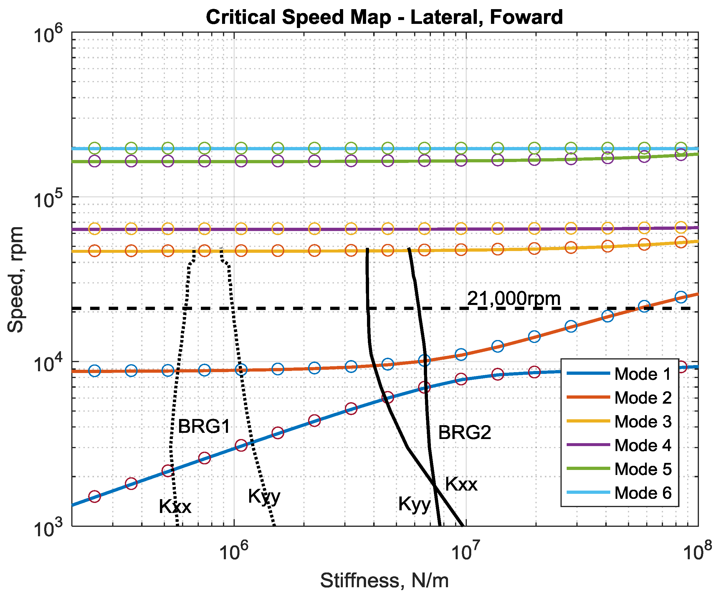
Figure 5 gives the critical speed map for the turbocharger rotor. The five-pad fixed-pad bearing stiffness values are plotted in the figure as well. The undamped forward mode shape, which is excited by unbalance, considering gyroscopic effect is given in Figure 6. The operating speed is 21,000 rpm between 2nd and 3rd modes at bearing stiffness region. The lower two modes are rigid body modes as shown in Figure 6, and this rotor operates below the first bending critical. As the rotor is also operating above the two rigid body natural frequency, the cross-coupling stiffness from bearings may excite oil whirl instability without proper bearing design.
8. Linear Rotor Stability Analysis
For linearized rotordynamics, the eigenvalues is used to identify the stability. If the real part of the eigenvalue is positive, the log decrement is negative and the rotor is linearly unstable. Linearly instability has two possible outcomes: one is a limit cycle orbit at bearing location or nonlinearly stable; and the other is catastrophic failure. The linear stability problem is given by Equation (12):
where Kb and Cb are the linearized bearing coefficients, and Q is cross-coupled stiffness from the seal. The cross-coupled stiffness decreases the stability of the system. In the following analyses, the system is found highly instable, so the seal effect was not considered in this paper.
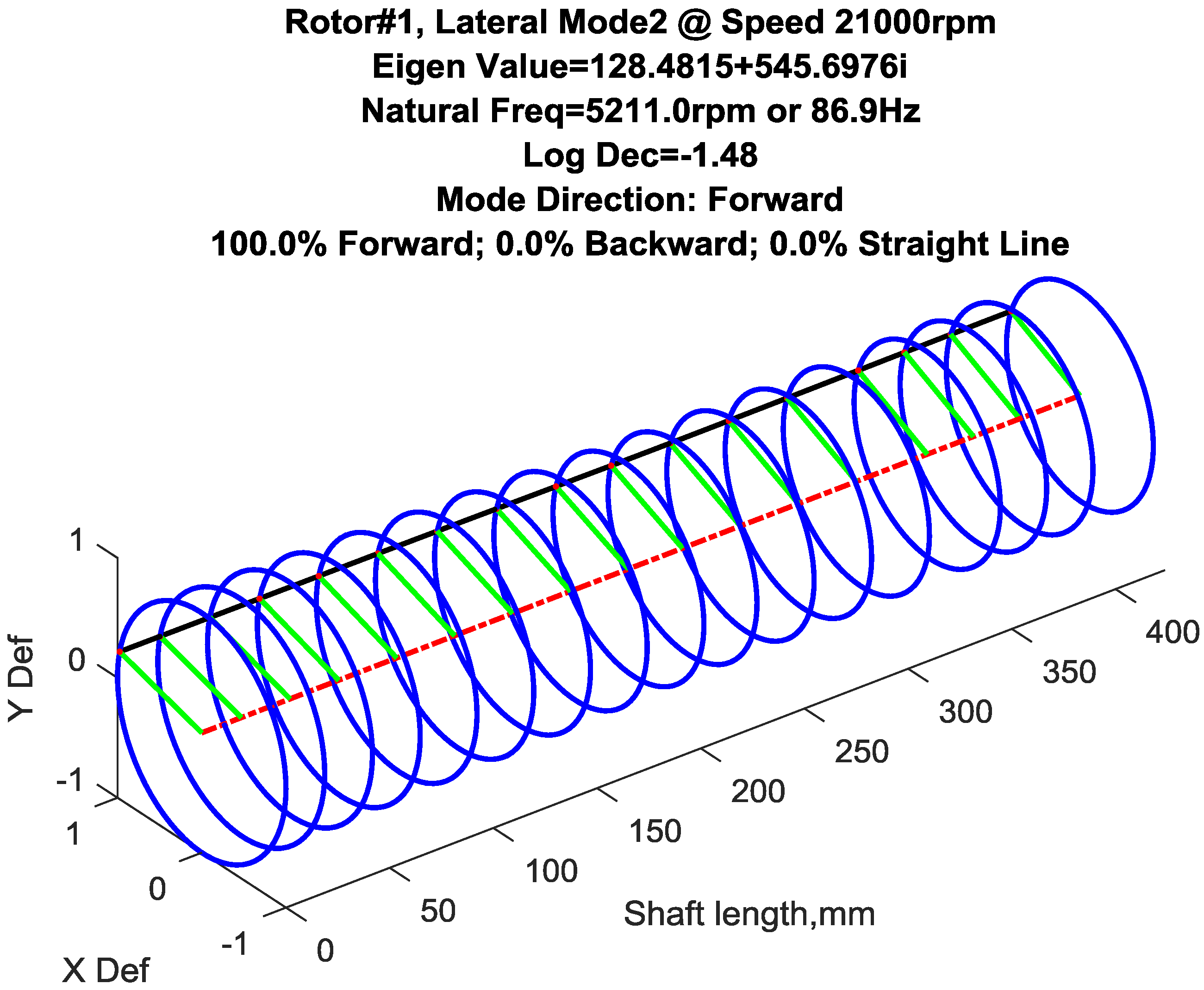
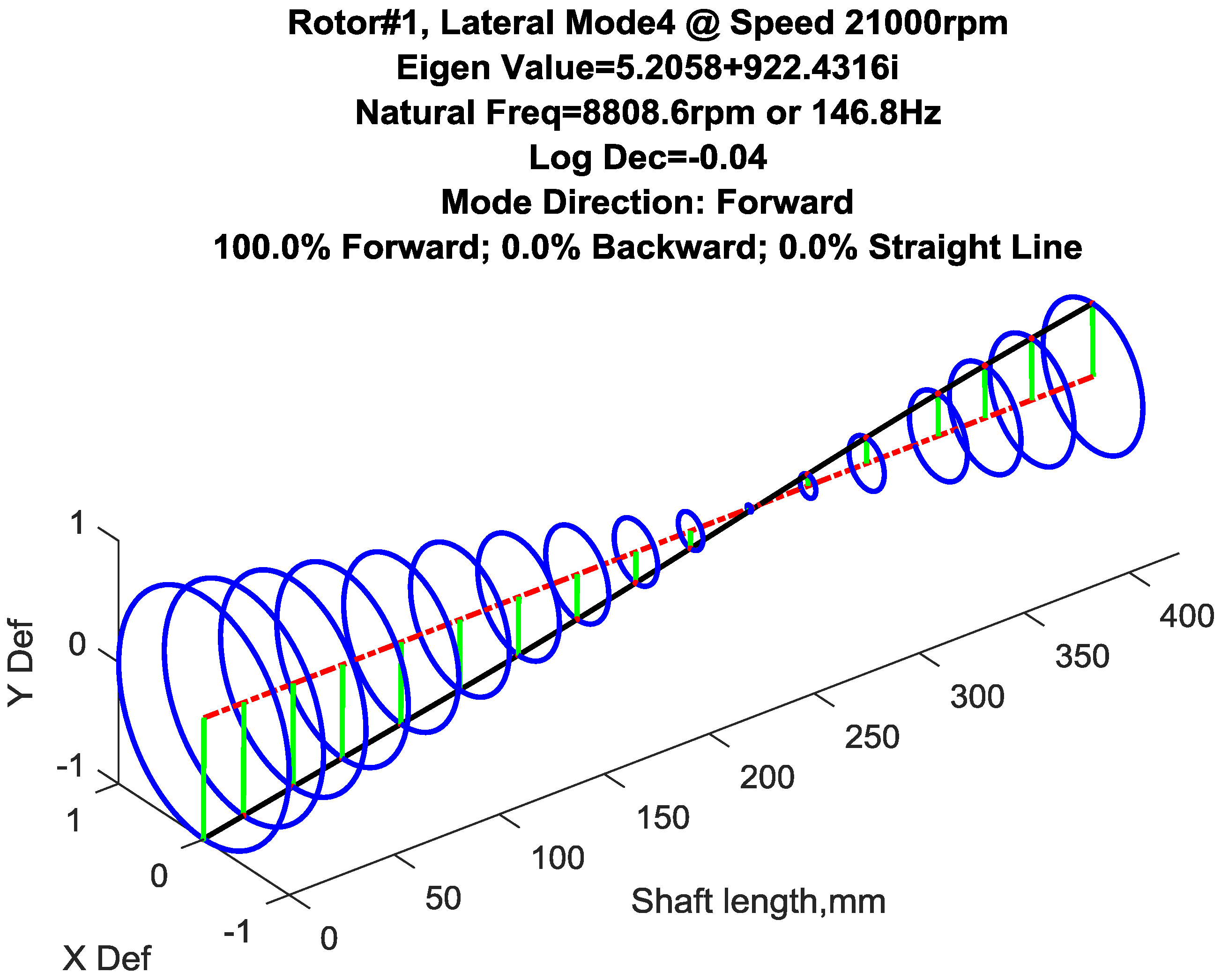
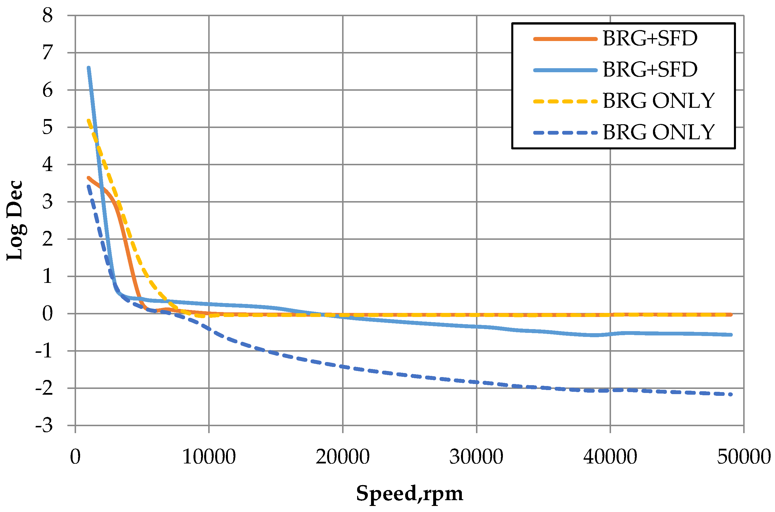
Using Equation (12), linear stability analysis was performed for the turbocharger. Figure 7 gives the unstable second mode shape and stability information for the rotor on the five-pad fixed-pad bearings without the squeeze film damper. Figure 8 shows the unstable fourth mode shape and instability information without the squeeze film damper. The log decrement vs. operating speed is shown in Figure 9 for these two modes. With speed increasing, the log decrement decreases and, over 8000 rpm, the system is unstable under linear steady analysis for both cases: bearing only and bearing with squeeze film damper (semi-floating bearing). With operating speed increases, two rigid modes has negative logarithmic decrement, which indicates the instability of the system, as shown in Figure 9. Introducing squeeze film damper increases logarithmic decrement of one rigid mode, but has few effects on the other rigid mode. The rotor is still unstable based on steady linear stability analysis under high operating speed.
9. Nonlinear Rotordynamic Response
For the nonlinear analysis, instead of calculating effective stiffness and damping coefficient, the bearing forces are considered at each time step based on current nodal displacement and velocity. The equation of motion for the turbocharger rotor then becomes:
where Mb is the mass of semi-floating bearing housing. The bearing forces in Equation (13) are those calculated using Equation (8). This method is the same as previously presented in Cao et al. [11]. The in phase unbalance of 2.5 G according to ISO 1940-1 for rigid rotor is applied to the two impellers to excite cylindrical rigid mode because of the higher logarithmic decrement in stability analysis (Figure 7).
10. Results
10.1. Nonlinear Transient Rotor/Bearing Response
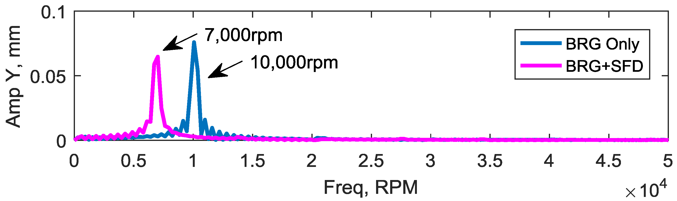
The nonlinear response of the turbocharger rotor with the five-pad fixed-pad bearings with and without squeeze film at the journal locations obtained using Equations (6) and (8) is shown in Figure 10. For both the fixed-pad bearing only case and semi-floating bearing case (BRG + SFD), the motions at the journals settle into a limit cycle. The limit cycle takes up about 90% of the bearing clearance for fixed-pad bearing case, and about 80% for semi-floating bearing case. For linear analysis, the shaft orbit at bearing location normally should less than 30%–40% of bearing clearance to use those linearized bearing stiffness and damping coefficients. Clearly, in this case, the limit cycle has generated due to large orbit. This relatively large orbit indicates large vibrational motion of the shaft, creating high pressures in the oil films and relatively large forces onto pads, due to significant shear stresses within the lubricating film. The large cycling force on the pads may result in a pad fatigue problem and finally may affect life of bearing. These large stresses result in significant power loss compared to a linearly stable bearing, as discussed in the next section. In frequency domain, we use FFT to examine the orbits. A sub-synchronous frequency occurs at 10,000 rpm and 7000 rpm for the two different bearings, as shown in Fast Fourier Transform (FFT) results of Figure 11. For orbit (blue) is the semi-floating bearing, the motion of semi-floating (damper) housing is shown in Figure 12, the about 25%–30% of clearance (red) and the housing is moving inside of the fixed-pad bearing. The sub-synchronous FFT frequency at 7000 rpm is the same as bearing-shaft relative response, as shown in Figure 13.
10.2. Bearing Force
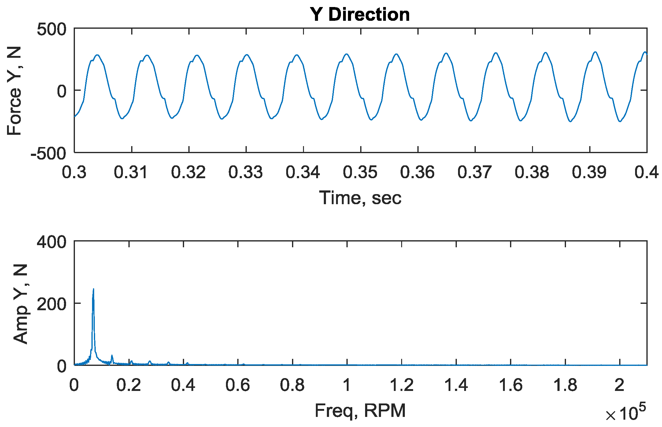
The large cycling oil film force on the pads, due to large shaft orbits, may result in a fatigue problem and may finally affect the life of bearing. The calculated pad forces, for the two bearing cases are shown in Figure 14 and Figure 15. Here, the results for only one pad (#4) of five pads from calculated force is given and compared. For the fixed-pad bearing without damper case, the maximum pad forces are 15 and 13.5 kN, for compressor end and turbine end bearings, respectively. However, for the semi-floating fixed-pad and squeeze film damper bearing case, the maximum force is only 0.65 and 0.35 kN for the compressor and turbine bearings. For the semi-floating bearing, the force generated at squeeze film damper is shown in Figure 16. This is a reduction of maximum pad forces of over 90%. The squeeze film damper and the inside bearing together support the shaft.
10.3. Power Loss
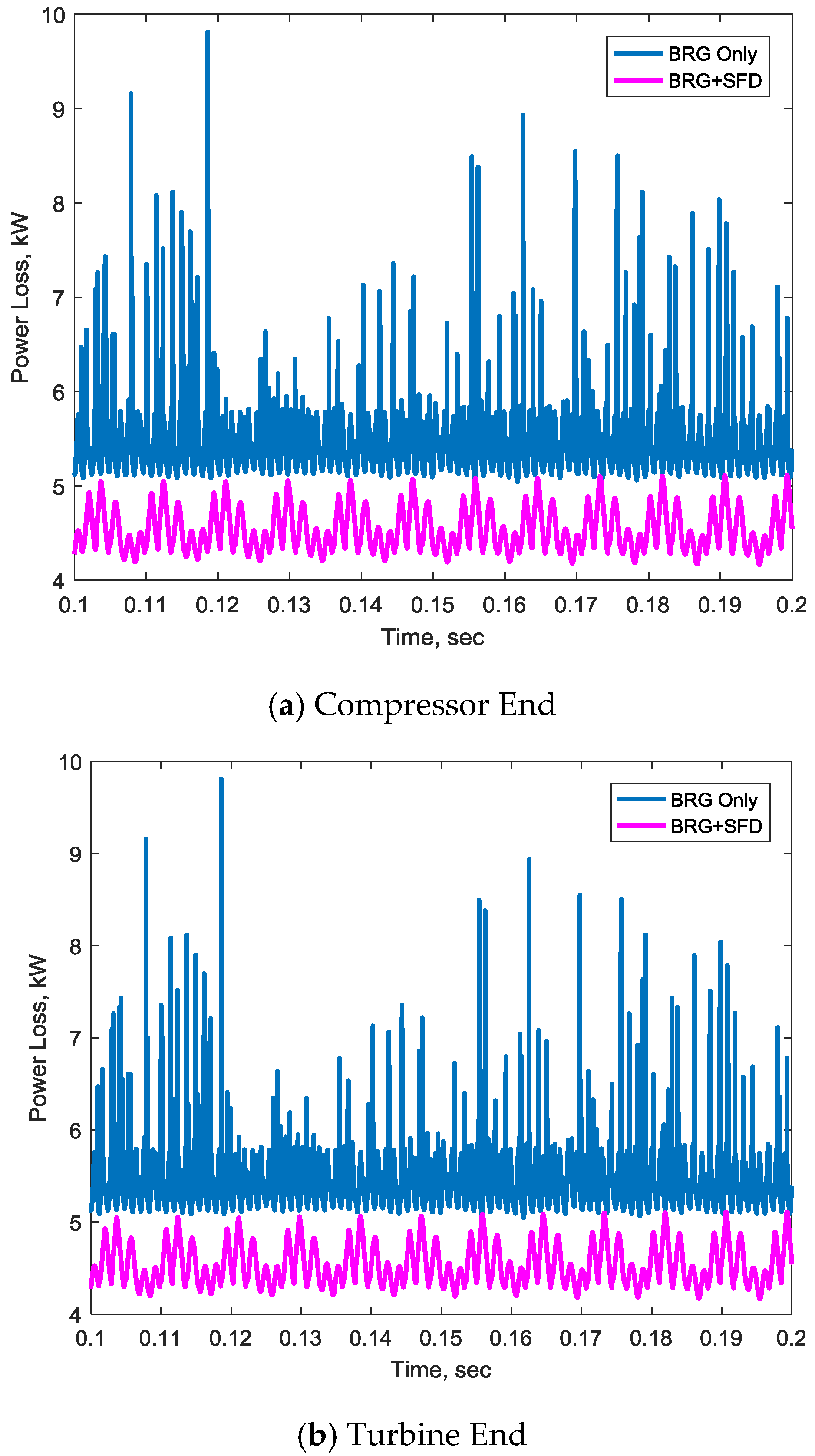
The power loss based on bearing steady analysis is not as accurate as that based on transient analysis for linearly unstable system [9]. Since the system is linearly unstable, the prediction for power loss for the fixed-pad bearings and the semi-floating bearings are all based on a nonlinear analysis and are shown in Figure 17 for the two end bearings.
Figure 17 shows the time-transient bearing power loss for the compressor end bearing and the turbine end bearing. Both bearings have similar power loss, but the power loss at fixed-pad bearing without the damper has large range than the semi-floating one with the damper. The power loss from damper is very small compare to bearing due to the whirl only motion. The average power loss varies between 5.1 kW–9.7 kW for the fixed-pad bearing only case and 4.3 kW–5.1 kW for the semi-floating bearing case.
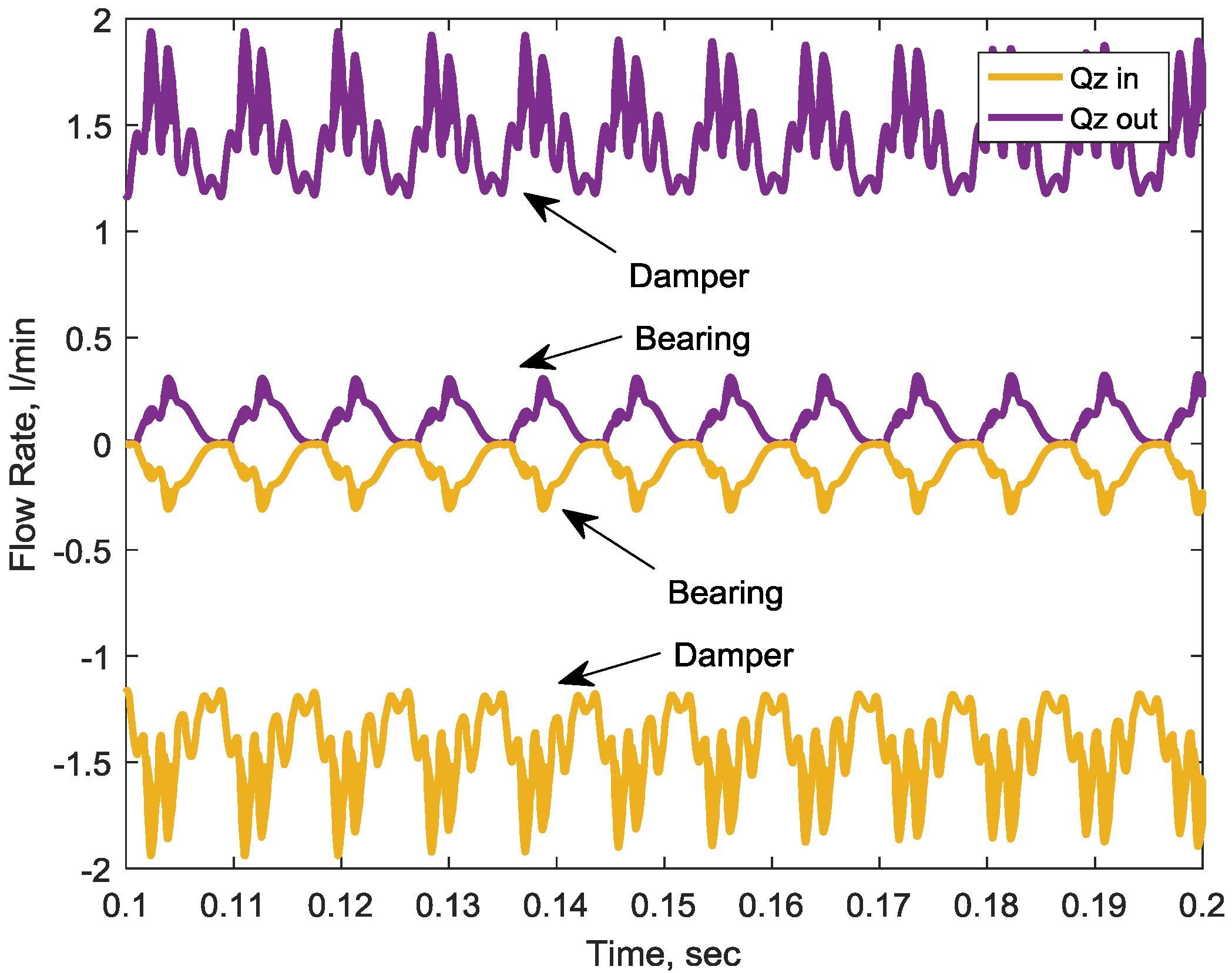
10.4. Flow Rate
The flow consumption depends upon the oil flow out of bearing from both axial ends of each bearing. The calculated flow rate of compressor end bearing are shown in Figure 18 for fixed-pad bearing, and Figure 19 shows the flow rate of semi-floating bearing at compressor end. In the figure, both flows from inner bearing and from the damper are given. The flow rates in axial direction from fix-pad bearing and from inner floating bearing are almost same, in the range of 0–0.5 L/min, since the limit orbits for two type bearings are similar. However, the semi-floating bearing flow is more stable than fixed-pad bearing, similar to pad force results and the power loss discussed in previous section.
There is more oil flow out from damper (1.9 L/min from one end) than the inner bearings, as shown in Figure 19. The main reason for this higher damper flow rate is that the floating housing has a smaller orbit clearance ratio, and the clearance of damper, under 0.127 mm, is bigger than bearing’s clearance, at under 0.09 mm.
11. Discussion
The linearized analysis showed that fixed-pad bearings only and semi-floating bearings could not to stabilize the rotor. The semi-floating bearing improves the stability, but the system is still linearly unstable, thus a time transient analysis method is required due to the significant cross-coupling effect at the bearing as well as the high rotational speed of 21,000 rpm. The nonlinear transient analysis shows that the bearing undergoes limit cycle motions of approximately 90% of the bearing clearance for the fixed-pad bearing without the squeeze film damper and approximately 80% of the clearance of the radial clearance with the damper included. Both bearing types experience a sub-synchronous frequency in the shaft orbits. The major difference between the two types of bearings is the very large reduction in the maximum pad forces for two bearing configuration: 15 kN vs. 0.65 kN, a reduction of approximately 95%. Thus, the expected fatigue lifetime of the semi-floating bearing design is expected to be much larger than the fixed-pad bearing design alone. The difference in power loss was 6.2 kW for the fixed-pad bearing alone vs. 4.5 kW on average for the semi-floating bearing design. However, more flow is needed for semi-floating bearing because of the higher flow from the damper larger clearance.
A more detailed analysis of the seal stiffness and damping properties is necessary to properly evaluate the linearized stability improvement by the semi-floating bearing. A simple fluid temperature model is used in this study due to slow energy solver. A faster 1D energy solver is still under development, however, a detailed seal analysis and energy solver were beyond the paper current scope.
12. Conclusions
The optimum design of fluid film bearings is rather complex in general but the additional complexity of the semi-floating bearing is significantly more difficult than most other bearings. Squeeze film dampers are one of least understood bearing configurations, as they are highly nonlinear devices so the optimization of this component alone is difficult.
The linear steady stability analysis of a high speed turbocharger showed that the rotor with the typical fixed-pad bearing design is highly unstable, and the semi-floating bearings were introduced due to the advantage of relatively low cost by using the normal fixed-pad bearing and adding squeeze film dampers outside of the fixed-pad bearing housings. After the semi-floating bearings are introduced, however, the turbocharger in this paper is still not a stable rotor due to the high rotor operating speed. The nonlinear transient analysis shows that the shaft orbits go into limit cycle orbits with acceptable amplitudes. The semi-floating bearing design was a large improvement over the original fixed-pad bearing design with much lower peak bearing forces then extends the long term fatigue life of the bearings. The maximum pad force from semi-floating bearing is only 4% of that from the fixed-pad bearing design, which should result in much higher bearing long term fatigue life. The power loss for semi-floating bearing component was 73% of the fixed-pad bearing power loss. However, a higher total oil supply or flow rate is required for the semi-floating bearing since more oil flows out from dampers with larger clearances.
Author Contributions
All authors worked together to finished the paper. Jianming Cao and Paul Allaire developed the analysis tools and performed the transient analyses; Tim Dimond and Saeid Dousti analyzed and discussed the data with the other authors; Jianming Cao wrote the main part of the paper; and Saeid Dousti and Paul Allaire wrote the introduction part.
Conflicts of Interest
The authors declare no conflict of interest.
References
- Gunter, E.J.; Chen, W.J. Dynamic Analysis of a Turbocharger in Floating Bushing Bearings. Available online: https://dyrobes.com/wp-content/uploads/2012/12/Dynamic-Analysis-of-a-Turbocharger-in-Floating-Bushing-Bearings-ISCORMA3-Gunter-Chen-2005.pdf (accessed on 12 June 2017).
- Schweizer, B. Total instability of turbocharger rotors—physical explanation of the dynamic failure of rotors with full-floating ring bearings. J. Sound Vib. 2009, 328, 156–190. [Google Scholar] [CrossRef]
- Tian, L.; Wang, W.J.; Peng, Z.J. Effects of bearing outer clearance on the dynamic behaviors of the full floating ring bearing supported turbocharger rotor. Mech. Syst. Signal Process. 2012, 31, 155–175. [Google Scholar] [CrossRef]
- Tian, L.; Wang, W.J.; Peng, Z.J. Dynamic behaviours of a full floating ring bearing supported turbocharger rotor with engine excitation. J. Sound Vib. 2011, 330, 4851–4874. [Google Scholar] [CrossRef]
- San, A.L.; Rivadeneira, J.C.; Gjika, K.; Groves, C.; LaRue, G. Rotordynamics of small turbochargers supported on floating ring bearings—highlights in bearing analysis and experimental validation. J. Tribol. 2007, 129, 391–397. [Google Scholar]
- Chen, W.J. Rotordynamics and bearing design of turbochargers. Mech. Syst. Signal Process. 2012, 29, 77–89. [Google Scholar] [CrossRef]
- Kelly, A.D. Rotordynamic Characterization and Comparison of Turbocharger Bearing Systems. In Proceedings of the 9th International Conference on Turbochargers and Turbocharging, London, UK, 19–20 May 2010. [Google Scholar]
- Shi, F.; Deng, D. An analysis for floating bearings in a turbocharger. SAE Tech. Pap. 2011. [Google Scholar] [CrossRef]
- Cao, J.; Dimond, T.; Allaire, P. Reduction of Vibration and Power Loss in Industrial Turbochargers With Improved Tilting Pad Bearing Design. In Proceedings of the ASME Turbo Expo 2015: Turbine Technical Conference and Exposition, Montreal, PQ, Canada, 15–19 June 2015. [Google Scholar]
- Friswell, M.; Penny, J.; Garcey, S.; Lee, A. Dynamics of Rotating Machines; Cambridge University Press: Cambridge, UK, 2010. [Google Scholar]
- Szeri, A. Fluid Film Lubrication: Theory and Design; Cambridge University Press: Cambridge, UK, 1998. [Google Scholar]
- Cao, J.; Allaire, P.; Dimond, T. Coupled lateral and torsional nonlinear transient rotor–bearing system analysis with applications. J. Dyn. Sys. Meas. Control. 2015, 137, 091011. [Google Scholar] [CrossRef]
- Kirk, R.G.; Gunter, E.J. Transient response of rotor bearing systems. ASME J. Manuf. Sci. Eng. 1974, 96, 682. [Google Scholar] [CrossRef]
- He, M. Thermoelastohydrodynamic Analysis of Fluid Film Journal Bearings. Ph.D Thesis, University of Virginia, Charlottesville, VA, USA, 2003. [Google Scholar]
Figure 1.
Schematic diagram of moderately large turbocharger and semi-flowing bearing.
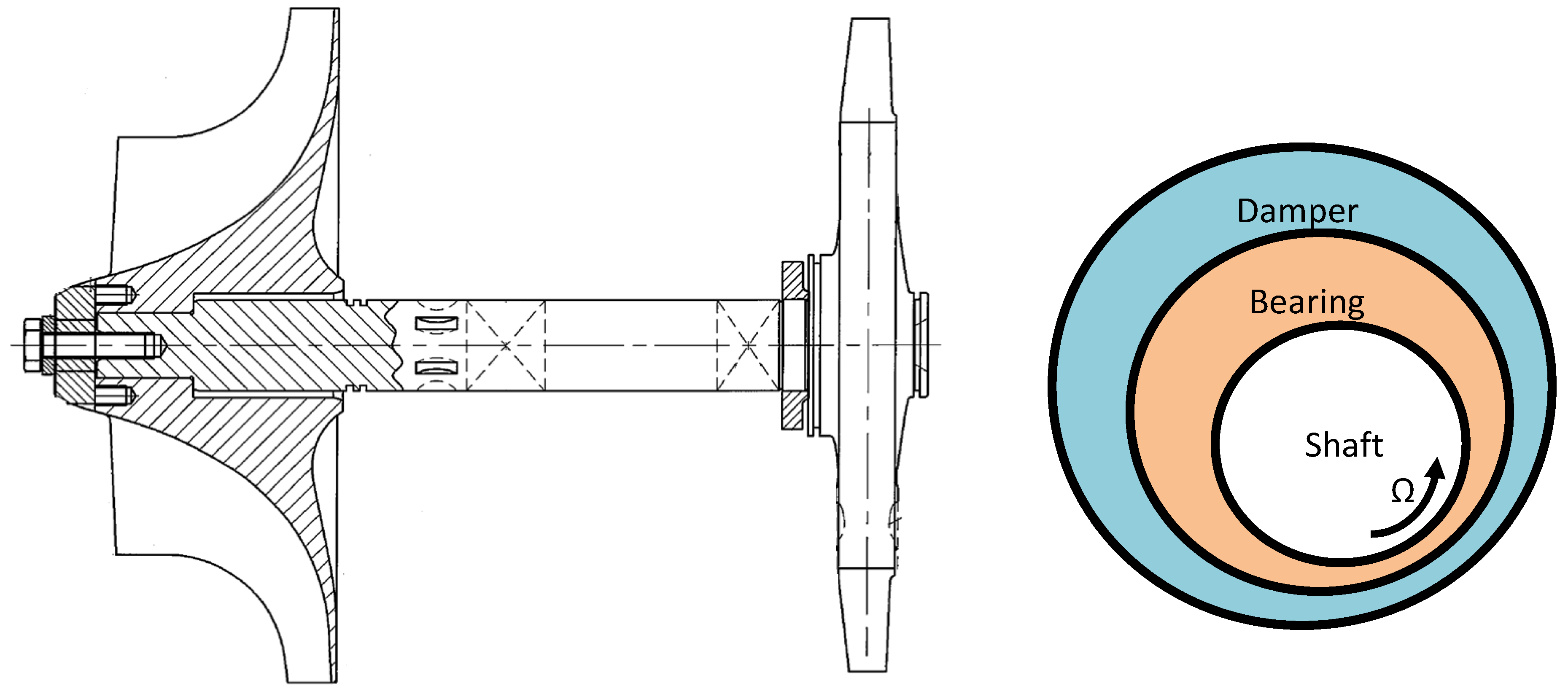
Figure 2.
Turbocharger rotor model (Green spots indicated the nodal location of wheels and bearings).
Figure 2.
Turbocharger rotor model (Green spots indicated the nodal location of wheels and bearings).
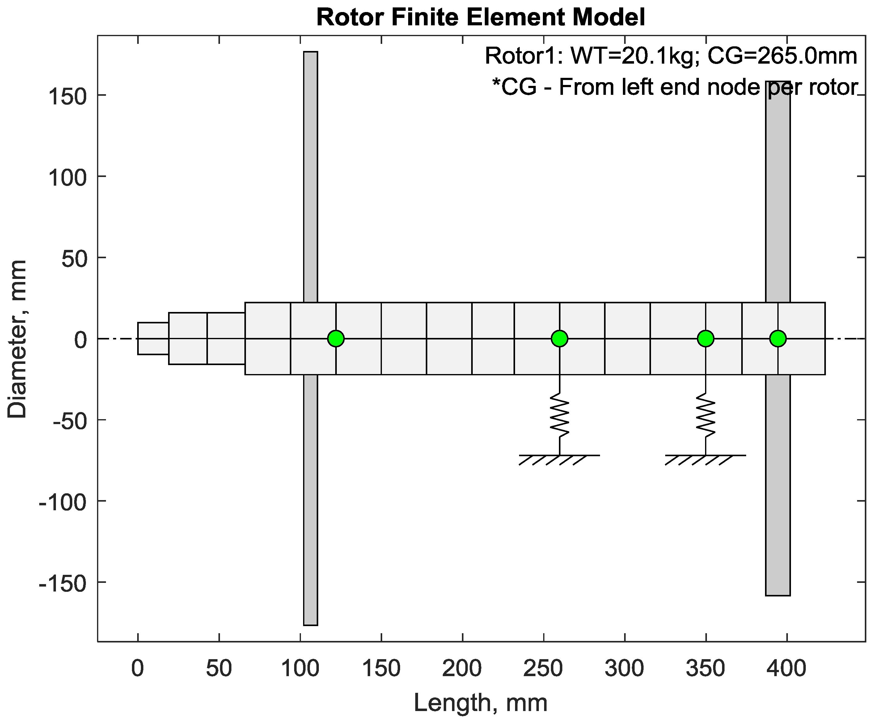
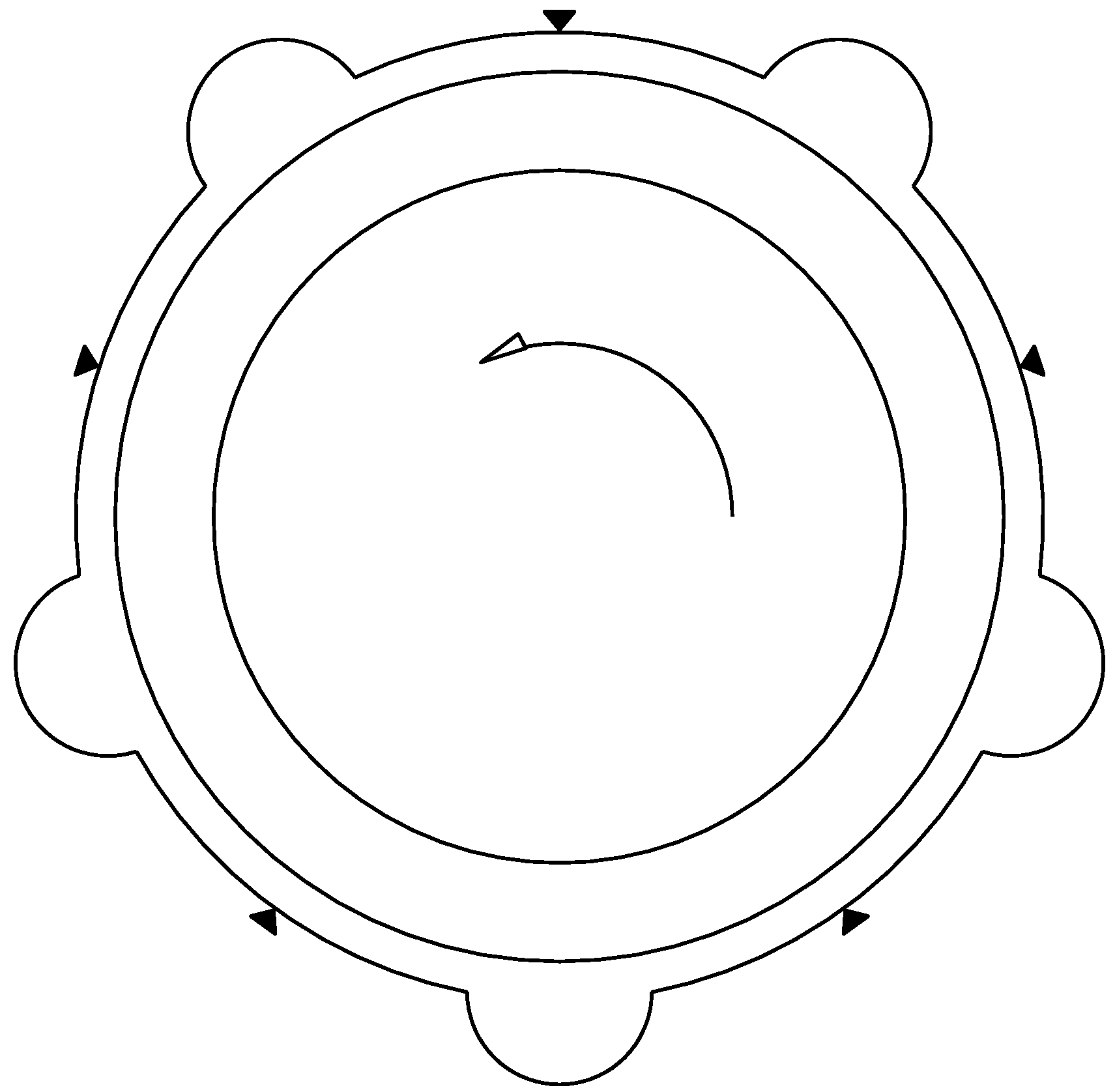
Figure 3.
Five pads fixed-pad inner film bearing diagram.

Figure 4.
Five pads fixed-pad bearing coefficients (without squeeze film dampers): (a) compressor end stiffness; (b) compressor end damping; (c) turbine end stiffness; and (d) turbine end damping.
Figure 4.
Five pads fixed-pad bearing coefficients (without squeeze film dampers): (a) compressor end stiffness; (b) compressor end damping; (c) turbine end stiffness; and (d) turbine end damping.
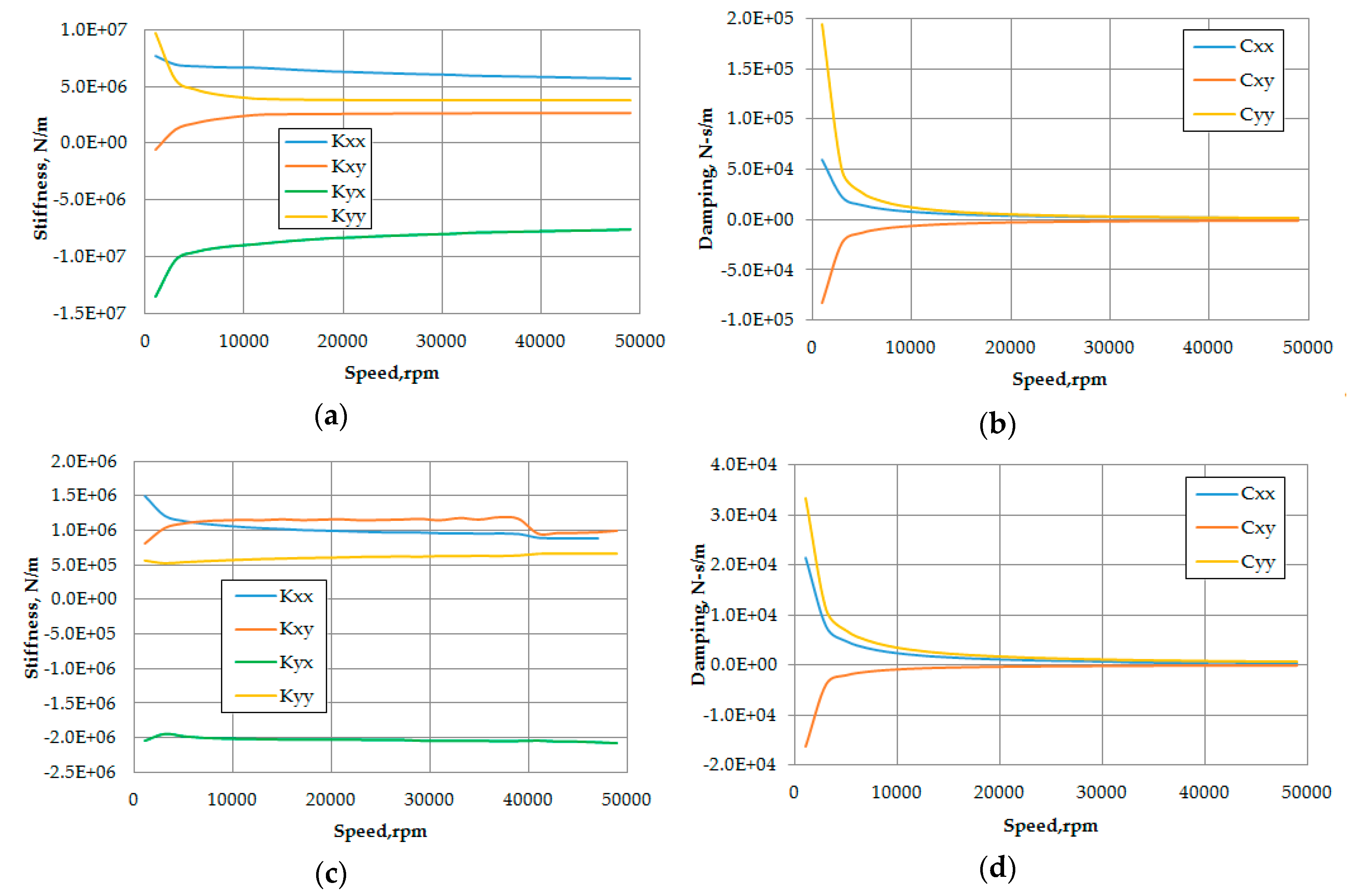
Figure 5.
Critical speed map with five-pad fixed-pad bearing (without damper).

Figure 6.
Undamped mode shapes for five-pad fixed-pad bearing (without damper).
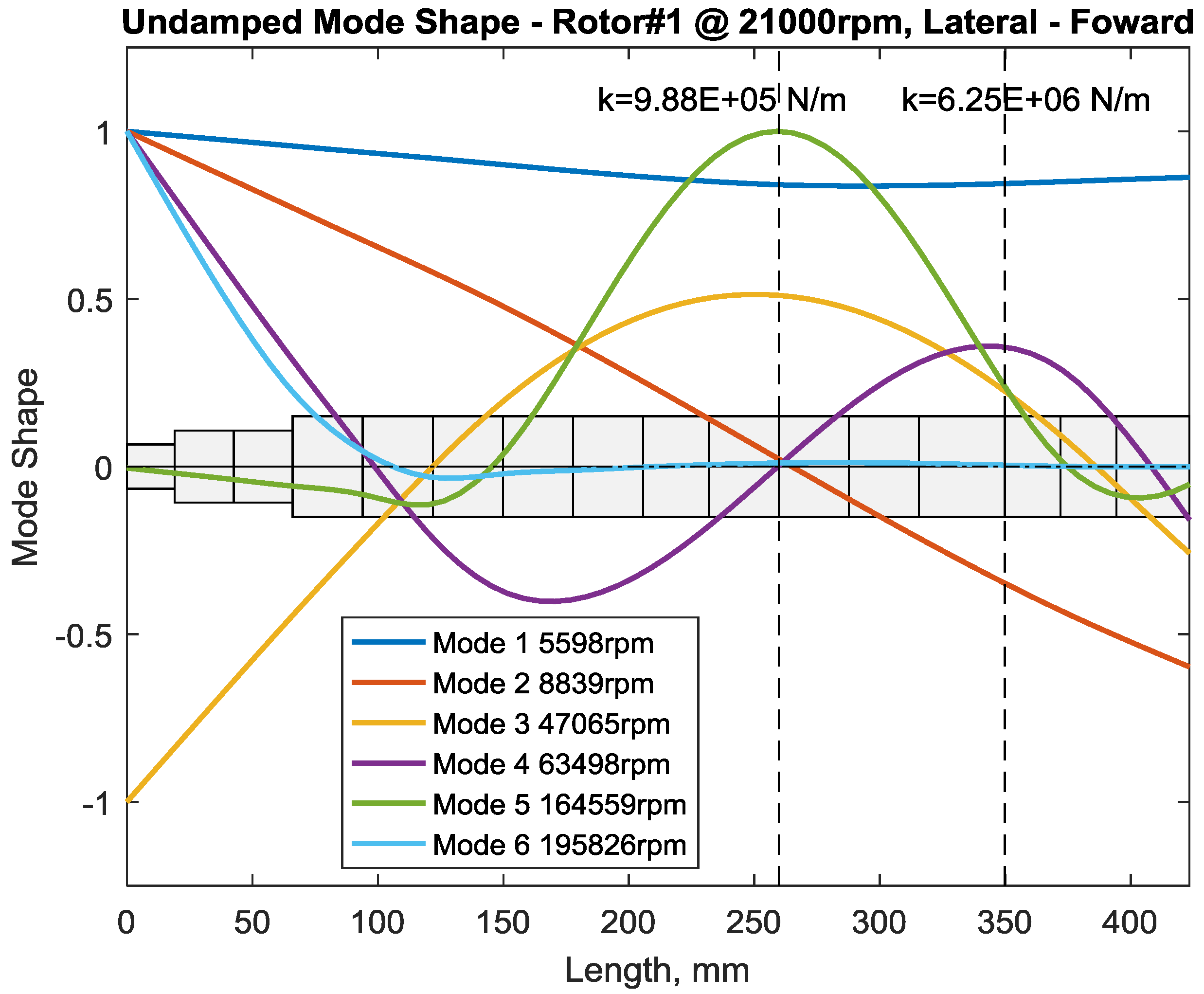
Figure 7.
Damped mode shape 2 with five-pads fixed-pad bearing (without squeeze film damper).

Figure 8.
Damped mode shape 4 with five-pads fixed-pad bearing (without squeeze film damper).

Figure 9.
Stability of turbocharger rotor in five-pad fixed-pad with and without squeeze film damper at different operating speeds
Figure 9.
Stability of turbocharger rotor in five-pad fixed-pad with and without squeeze film damper at different operating speeds

Figure 10.
Bearing orbits in limit cycles with and without squeeze film dampers: (a) compressor end; and (b) turbine end.
Figure 10.
Bearing orbits in limit cycles with and without squeeze film dampers: (a) compressor end; and (b) turbine end.

Figure 11.
FFT analysis of bearing orbits with and without squeeze film dampers.

Figure 12.
Damper housing orbits with fixed-pad bearings and squeeze film dampers: (a) compressor end; and (b) turbine end (Blue line indicates orbit, and red line indicates clearance).
Figure 12.
Damper housing orbits with fixed-pad bearings and squeeze film dampers: (a) compressor end; and (b) turbine end (Blue line indicates orbit, and red line indicates clearance).

Figure 13.
FFT of damper housing orbits with fixed-pad bearings and squeeze film dampers.
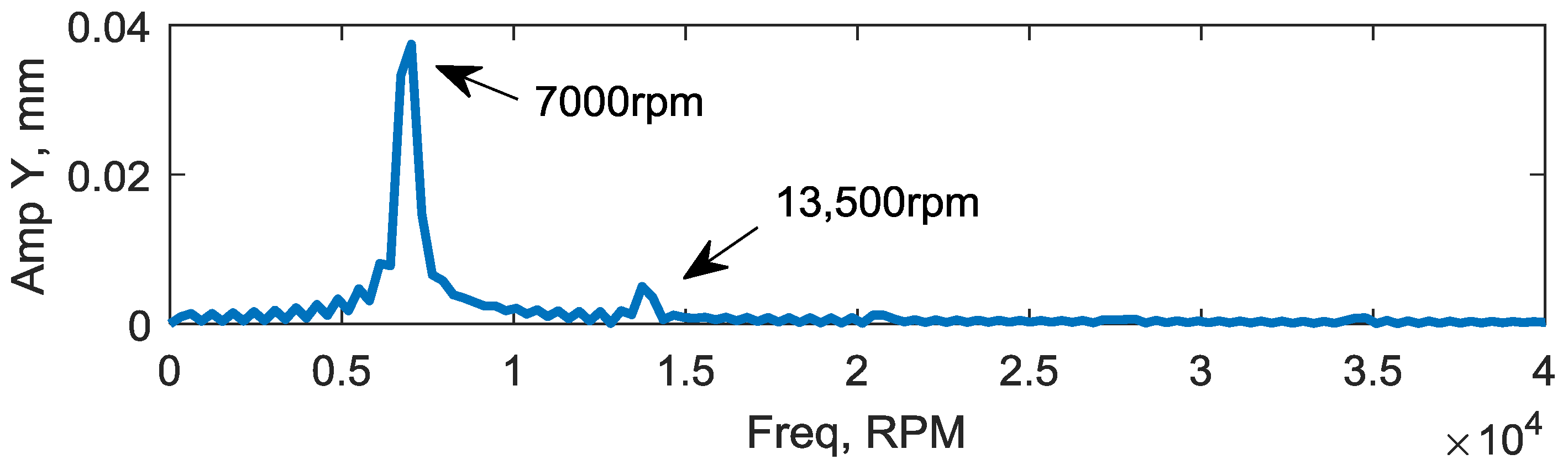
Figure 14.
Bearing-pad force at compressor end.
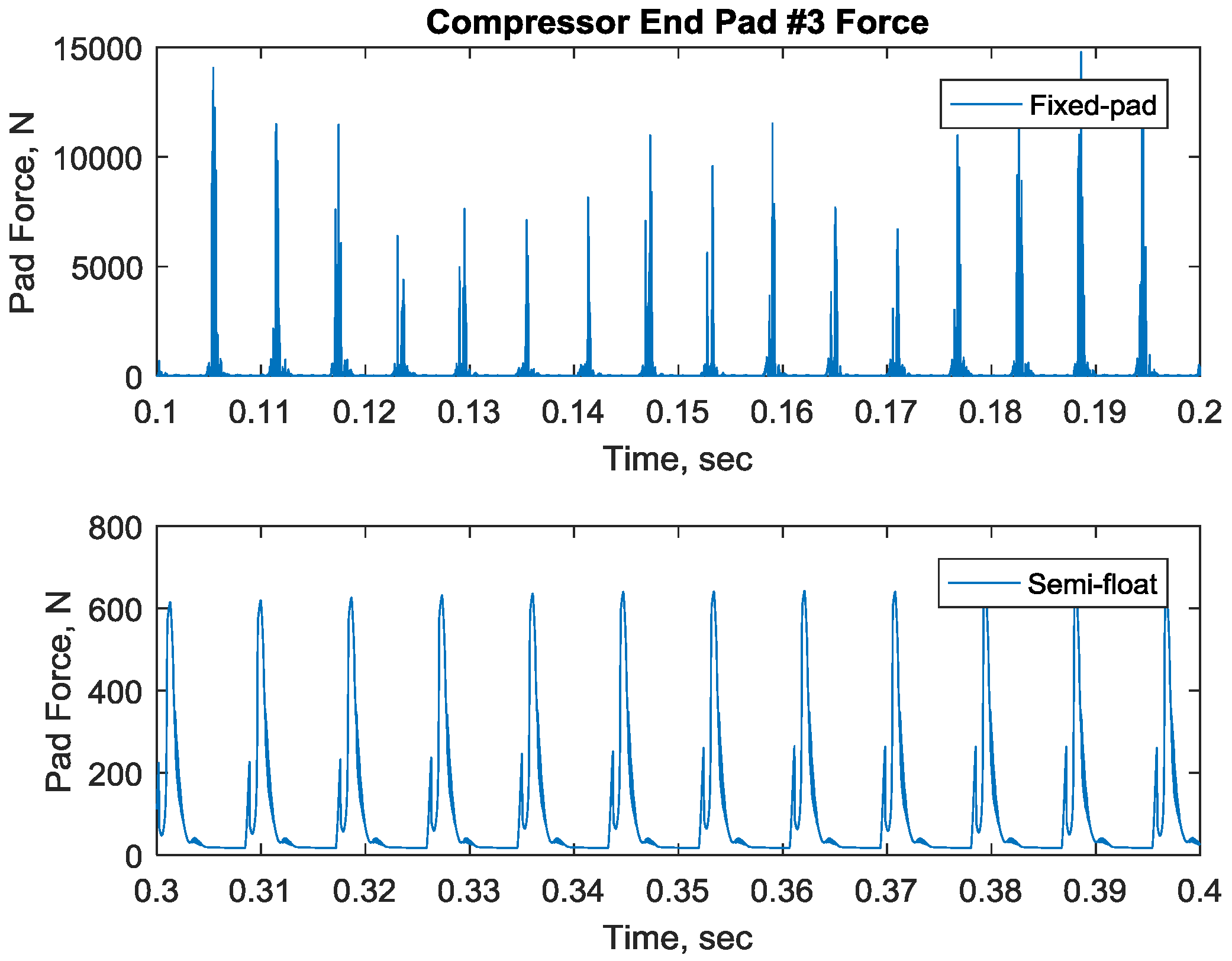
Figure 15.
Bearing-pad Force at Turbine End
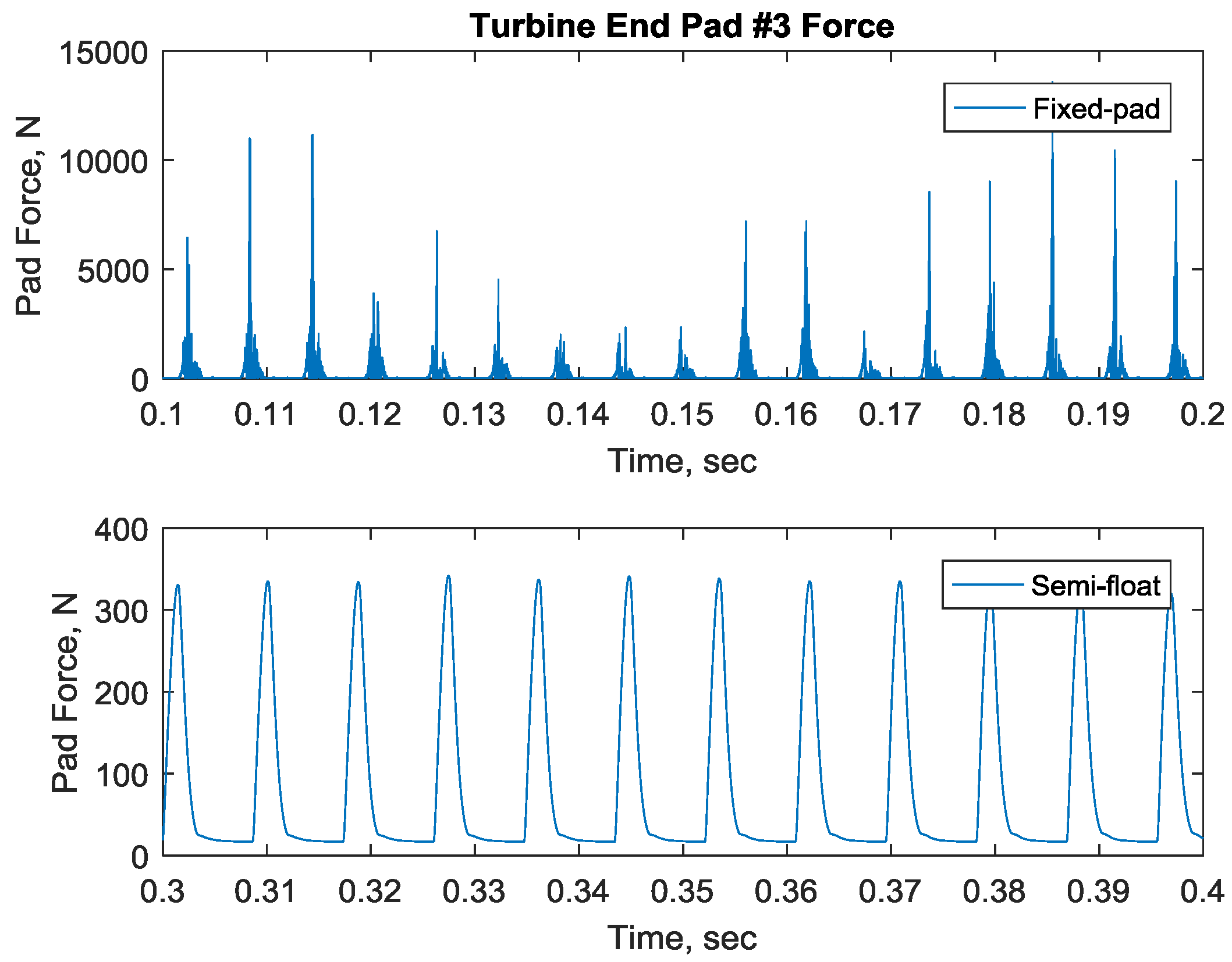
Figure 16.
Squeeze film damper force.

Figure 17.
Time transient bearing power losses in compressor and turbine end bearings: (a) compressor end; and (b) turbine end
Figure 17.
Time transient bearing power losses in compressor and turbine end bearings: (a) compressor end; and (b) turbine end

Figure 18.
Bearing flow rate—fixed-pad bearing only case.
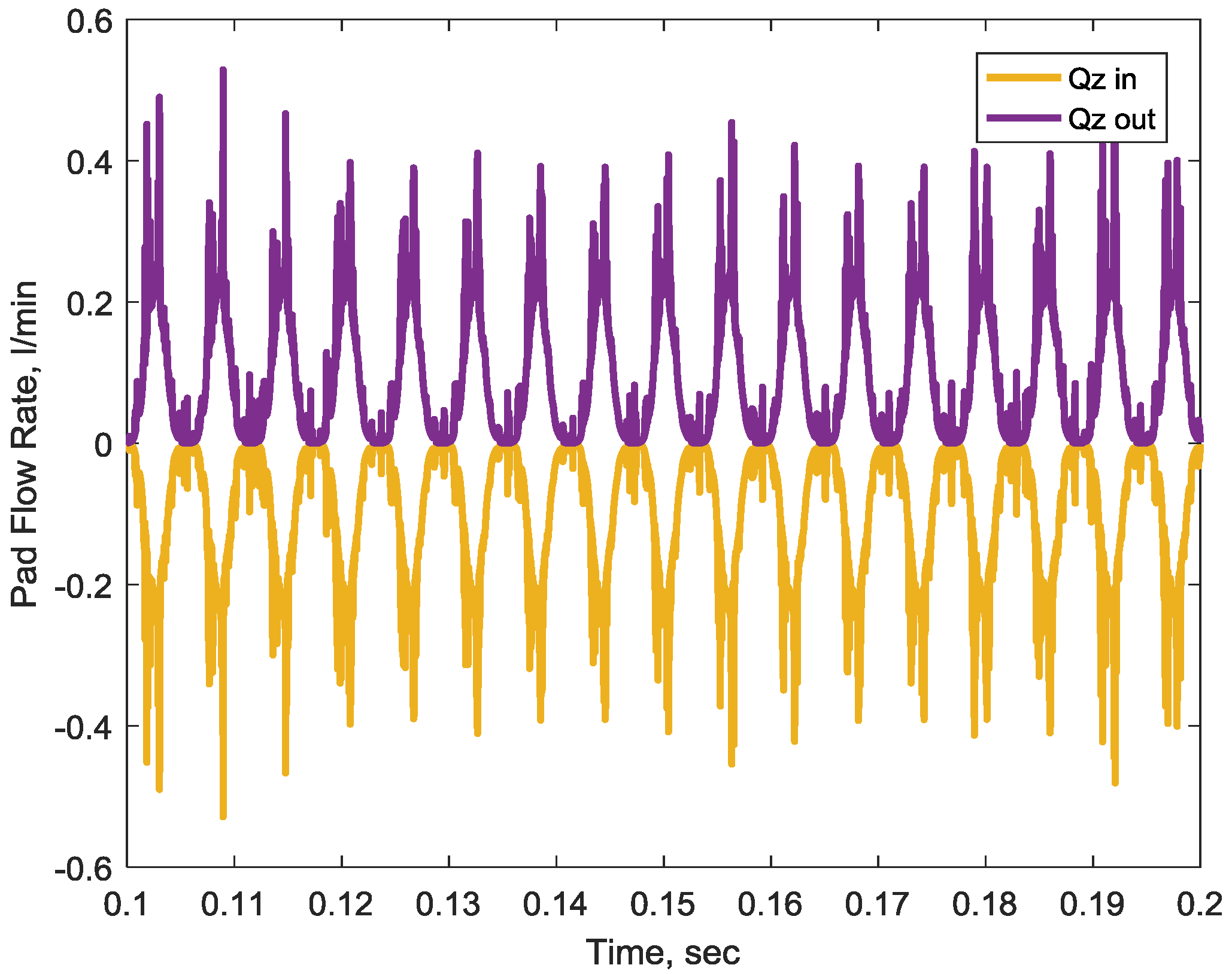
Figure 19.
Bearing flow rate—fixed-pad bearing and damper case.


Table 1.
Five pads fixed-pad bearing information.
| Property | Value | Unit |
|---|---|---|
| Diameter | 44.94 | mm |
| Length | 12.5 | mm |
| Bearing Clearance | 0.0896 | mm |
| Pad Angle | 50 | Deg |
| Pivot Location | 18, 90, 162, 234, 306 | Deg |
| Offset | 50% | |
| Preload | 0 | |
| Bearing Load | −161.8 (Compressor End) −35.3 (Turbine End) | N N |
| Oil | ISO VG32 | |
| Oil Inlet Temperature | 60 | °C |
Table 2.
Squeeze film damper information.
| Property | Value | Unit |
|---|---|---|
| Diameter | 65.07 | mm |
| Length | 12.5 | mm |
| Bearing Clearance | 0.127 | mm |
| Oil | ISO VG32 | |
| Oil Inlet Temperature | 60 | °C |
© 2017 by the authors. Licensee MDPI, Basel, Switzerland. This article is an open access article distributed under the terms and conditions of the Creative Commons Attribution (CC BY) license (http://creativecommons.org/licenses/by/4.0/).
Share and Cite
MDPI and ACS Style
Cao, J.; Dousti, S.; Allaire, P.; Dimond, T. Nonlinear Transient Modeling and Design of Turbocharger Rotor/Semi-Floating Bush Bearing System. Lubricants 2017, 5, 16. https://doi.org/10.3390/lubricants5020016
AMA Style
Cao J, Dousti S, Allaire P, Dimond T. Nonlinear Transient Modeling and Design of Turbocharger Rotor/Semi-Floating Bush Bearing System. Lubricants. 2017; 5(2):16. https://doi.org/10.3390/lubricants5020016
Chicago/Turabian StyleCao, Jianming, Saeid Dousti, Paul Allaire, and Tim Dimond. 2017. "Nonlinear Transient Modeling and Design of Turbocharger Rotor/Semi-Floating Bush Bearing System" Lubricants 5, no. 2: 16. https://doi.org/10.3390/lubricants5020016
Note that from the first issue of 2016, this journal uses article numbers instead of page numbers. See further details here.