Article

MD Sliding Simulations of Amorphous Tribofilms Consisting of either SiO2 or Carbon

by
Andrey I. Dmitriev
1,2,3,
Anton Yu. Nikonov
1,2 and
Werner Österle
4,*
1
Institute of Strength Physics and Materials Science, 634021 Tomsk, Russia
2
Department of Metal Physics, Tomsk State University, 634050 Tomsk, Russia
3
Department of Automated Engineering Technology, Tomsk Polytechnic University, 634050 Tomsk, Russia
4
Federal Institute for Materials Research and Testing, 12200 Berlin, Germany
*
Author to whom correspondence should be addressed.
Lubricants 2016, 4(3), 24; https://doi.org/10.3390/lubricants4030024
Submission received: 21 April 2016 / Revised: 17 June 2016 / Accepted: 21 June 2016 / Published: 29 June 2016
(This article belongs to the Special Issue Tribofilms and Solid Lubrication)

Abstract

:
The sliding behaviors of two simplified tribofilms with amorphous structure consisting either of SiO2 molecules or C atoms were simulated by molecular dynamics modeling. The objective was to identify mechanisms explaining the experimentally observed lubricating properties of the two amorphous films. The impacts of layer thickness, normal pressure, temperature and different substrate materials were studied systematically, while the sliding velocity was kept constant at 30 m/s. While the layer thickness was not critical, all the other parameters showed special effects under certain conditions. Normal pressure impeded void formation and could even eliminate voids if applied at high temperature. Stick-slip sliding was changed to smooth sliding at high temperature due to void healing. Considering the carbon film, high friction forces and shearing of the entire film was observed with diamond substrates, whereas interface sliding at low friction forces and an amorphous layer of iron mixed with carbon was observed if the supporting substrates consisted of α-Fe. Both films show a decrease of friction forces and smooth sliding behavior at elevated temperature, corresponding well to the tribological behavior of an advanced nanocomposite sliding against a steel disc under severe stressing conditions when high flash temperatures can be expected.

Graphical Abstract

1. Introduction

Molecular dynamics (MD) simulations have been performed comprehensively by Rigney and coworkers to show structure formation at the sliding interface of pure crystalline materials [1,2,3,4]. Although only a two-dimensional (2D) model was applied, the following features were visualized on the atomic scale: (i) mixing of the two first body materials; (ii) evolution of defect potential energy in the vicinity of the interface and (iii) formation of nanocrystalline structures [1]. Furthermore, it was observed that a highly disordered layer developed in the softer material of the sliding couple and it was suggested that this layer may behave like a liquid [1]. For a Fe–Cu couple, the whole shear deformation occurring during sliding was concentrated within a superficial amorphous layer at the copper surface [2]. The width of the amorphous layer increased with the increasing simulation time [3]. Similar results were obtained for a Fe–Al couple [4]. A three-dimensional (3D) MD simulation of a nanometric scratch test comprising a diamond tool and a copper single crystal was performed by Zhu et al. [5]. Again, an amorphous layer was observed at the surface and within the formed chip of the softer material, i.e., copper. Whereas the recrystallization of amorphous copper was observed in [4], this was not the case in [5], most likely because a thermostat was incorporated in the model structure.
Morita et al. presented an extended MD model, taking into account possible chemical reactions between different atomic species [6]. With this model they could show that an amorphous MoS2 tribolayer bound by iron substrates on both sides may crystallize with alignment of its basal planes parallel to the sliding interface, thus explaining the ultra-low friction of this system. Experimental evidence for this mechanism was provided, e.g., by Theiler et al. [7].
There are other tribofilms with amorphous structure also providing excellent friction and wear properties, but without evidence of crystallization. Numerous papers report on amorphous carbon coatings which may provide either graphite-like (GLC) or diamond-like (DLC) behavior. Although the beneficial effects on friction and wear reduction are beyond dispute, the reasons are not so obvious. Pastewka et al. performed MD simulations on hydrogenated amorphous carbon (a-C:H) [8]. They observed two effects which might be responsible for the observed friction reduction. Firstly, there was a local transformation of sp3 to sp2 bonding states at the sliding interface. Furthermore, the passivation of dangling bonds seems to play an important role [8]. The importance of the local sp3–sp2 transition and the corresponding formation of a soft amorphous layer were corroborated by a further study [9]. Furthermore, it was demonstrated that the polishing of a diamond crystal with a suspension of diamond particles depends on the formation of an amorphous layer and local sp3–sp2 transition [10].
A further type of beneficial amorphous tribofilm is formed from the anti-wear oil additive zink dialkyl dithiophosphate (ZDDP). MD sliding simulations of such a film supported by crystalline iron substrates on both sides were performed by Martin et al. [11]. The study demonstrates that not only the polyphosphate retains its amorphous structure, but it also has the capability to “digest” abrasive iron oxide nanoparticles during the sliding simulation. Furthermore, the incorporation of iron atoms into the zinc polyphosphate glass alters the shear distribution within the tribofilm considerably [11].
Our own interest in amorphous tribofilms originates from experiences made with hybrid polymer-based nanocomposites which were developed for anti-friction and anti-wear applications [12,13]. It has been shown that only if the composites contain both micron-sized carbon fibers and a certain amount of silica nanoparticles, the desired low friction and wear properties are preserved during severe stressing conditions. This was attributed to the formation of a silica-based tribofilm which also was proved experimentally. A prerequisite of silica release from the composite matrix, the epoxy resin, is a local temperature increase (flash temperature) at the primary contact sites, the carbon fibers. A recently developed method of flash temperature assessment yielded a temperature of at least 860 °C for a similar material [14]. From this we conclude that a temperature of approximately 1100 K has to be taken into account, not only for explaining the degradation of the polymer and the release of silica nanoparticles, but also as the temperature under which sliding takes place. This approach is different compared to all previous MD sliding simulations which were performed at an initial temperature of 273 K.
Österle et al. [13] explained the anti-friction behavior of the silica-based tribofilm with a nanoscopic model based on movable cellular automata (MCA). Actually, smooth sliding and a rather low coefficient of friction (COF) of 0.2 were predicted if the silica nanoparticles constituting the tribofilm were mixed with either 10% graphite or 20% epoxy (volume fractions). The very low COF of 0.06 observed under the most severe stressing conditions, i.e., if the product of pressure and sliding velocity was equal to 24 MPa·m/s, could not be explained by MCA modeling [13]. Since both amorphous carbon and the silica-based film were observed in the wear scar, their sliding behavior was the focus of interest. Thus, the objective of the present study was to find out whether MD modeling can provide useful information for obtaining a better understanding of the exceptional tribological properties of the considered hybrid nanocomposite under the most severe stressing conditions. Since the latter lead to high flash temperatures, it was necessary to perform the simulations at elevated temperature.

2. Results

2.1. Modeling Setup

The initial structure was always a perfect crystal built from the elements of the considered material. In the case of silica, the structure was formed by bonding Si–O tetrahedra together, as shown in Figure 1b. The dimensions of the single crystal silica specimen built by this procedure are shown in Figure 1a. The modeled volume was 15 nm in width, 40 nm in height and 8.3 nm in thickness, corresponding to the x, y and z axes, respectively. Amorphous layers of different thicknesses were produced by a procedure described in Section 4. The model structure usually consisted of an amorphous layer supported at both sides by crystalline substrates. Four different amorphous layer thicknesses were realized comprising 10%, 20%, 50% and 75% of the crystal block. Thus, the amorphous layer was always supported by a stiff crystalline substrate. To imitate an extension of a specimen, periodic boundary conditions were assigned in the x and z directions. Thus, for example, each atom crossing the left border of the specimen immediately was moving into the specimen again from the right side. Sliding simulations were performed by applying a constant sliding velocity of +15 and −15 m/s to the lower and upper surface layers, respectively. Thus, the total sliding velocity was 30 m/s. First simulations were performed without the application of normal pressure. Later, a normal force of 260 nN was applied along +y and −y directions, yielding a total contact pressure of about 4 GPa. The influence of temperature on the sliding behavior was studied as well. Two temperatures, namely 300 K (room temperature) and 1100 K (flash temperature), were considered. Temperature was kept constant for each simulation. Thus, frictional heating was not simulated, but the consequence of frictional heating on the sliding behavior at nano-sized contacts was considered.

2.2. Sliding Simulations of Amorphous Silica Layers at 300 K

First simulations were performed with amorphous silica layers of different thicknesses at room temperature. Examples of structure formation with increasing simulation time are shown in Figure 2 and Figure 3 for the 20% and 75% amorphous samples, respectively. The green lines correspond to marker atoms, indicating the regions of atomic movements. It is obvious that the atoms of the crystal do not move relative to their neighbors, although the upper part is forced to move into the opposite direction as the lower part. The shear deformation needed for the compensation of the drift between the upper and lower part of the specimen occurs in the amorphous layer. Already in an early stage of sliding, bonds are broken and crack-like features are formed. After this has happened, shearing is constricted to the ligaments between the damaged regions. Increasing the thickness of the amorphous layer does not change this mechanism in principle. Interestingly, a 20-nm-thick damaged layer of intense shearing is observed also for the thick layer, whereas the major part of this amorphous layer behaves like the crystalline substrate. Towards the end of a simulation we sometimes observed cross-sections showing features with almost circular shape (Figure 4). Such features seem to adopt the function of nano-sized rollers.

2.3. Sliding Simulation of an Amorphous Silica Layer at 1100 K

The same configuration was also studied at 1100 K. This temperature corresponds to the flash temperature which is expected if a composite reinforced with carbon fibers is sliding against a steel disc [14]. The corresponding structure evolution is shown in Figure 5.
Again, the velocity accommodation between the upper and lower part of the specimen occurs almost entirely within the amorphous layer. In contrast to room temperature, no damaged regions are observed and shearing takes place homogeneously within the whole layer. Furthermore, the thickness of the amorphous layer increases with time during the simulation. Instead of the movement of aggregates of linked atoms, as observed at 300 K, now single atoms move like they do in liquid films—in opposite directions along the interface between the upper and lower part and a neutral layer in the middle. This is shown in Figure 6.
Besides significant differences in structure evolution, the tangential forces needed to enforce the beginning of sliding with the overall velocity of 30 m/s and at temperatures of 300 K and 1100 K differ as well. This is shown in Figure 7a.
The formation of voids and the movement of nano-sized rollers along the sliding interface region cause a stick-slip type of behavior at room temperature. The sliding of the same layer at the elevated temperature of 1100 K is very smooth and the friction force required to initiate relative sliding is much lower (750 nN vs. 2000 nN). Only after a certain period of simulation time at room temperature, the mean value of the friction force also seems to approach a much lower value. This may be due to the nano-sized rollers between the separated upper and lower parts of the model structure. Figure 7b shows the time dependence of the friction force for the 10%, 20% and 75% amorphous layers at room temperature. These diagrams confirm that at first, high values of the resistance force are needed to initiate sliding. This indicates that some time is needed to form the first voids. For the thin amorphous layers, more time is needed to form the voids. After the nano-sized rollers were formed, the resistance force decreased abruptly.

2.4. Impact of External Pressure on Structure Formation of the 20% Amorphous Silica Layer

The application of 2 GPa normal pressure to both sides of the model structure, resulting in a total pressure of 4 GPa, exerted significant changes on the structure formation. Several sliding simulations under this pressure were performed, and the most interesting results are shown in Figure 8.
Contrary to the simulation without pressure, no damaged region with formation of cracks and voids is observed in Figure 8a. The following study was performed to consider the sliding behavior of a layer already containing a void before starting the sliding simulation with applied pressure. This structure was produced as described in Section 2.2 and is now taken as the starting point. Figure 8b shows this situation. The green marker atoms are aligned in a row indicating that no shearing has occurred yet. If this configuration was subjected to a sliding simulation at room temperature under applied pressure, the sliding behavior and further structure evolution were similar as observed previously (compare Figure 8c and Figure 2). The void is preserved, at least up to a simulation time of 0.5 ns, and the shear deformation is concentrated within the damaged zone. The situation changes completely if the simulation is performed at 1100 K. Due to the applied pressure during the sliding simulation, the void is closed and the shear deformation is distributed over the whole layer thickness. This resembles closely the behavior of the undamaged layer without applied pressure at the same temperature (Figure 2). The only difference is that the layer thickness has not increased due to the applied pressure. It seems that the additional amorphous material produced during sliding fills the void which was originally present at the center of the layer. Tangential reaction forces also look similar. The latter results will be discussed in Section 3.

2.5. Sliding Simulations of Amorphous Carbon Layers

Amorphous carbon interlayers were produced by the procedure described in Section 4. Two types of substrates were considered, diamond and α-Fe. The first configuration resembles the one chosen for silica, just providing stiff substrates with firm chemical bonding to the amorphous layer on both sides. The second material pair considers an amorphous carbon layer adhering to a steel substrate similar to a transfer film from a carbon fiber–reinforced polymer matrix composite sliding against a steel disc. Again, a pressure of 4 GPa was applied and sliding simulations were performed at 300 K and at 1100 K, corresponding to room temperature and the expected flash temperature, respectively. Figure 9 shows the results obtained for the amorphous carbon layer supported by diamond crystals at 300 K and 1100 K.
By applying 4 GPa pressure the density of the amorphous carbon is increased, reaching almost the density of diamond. Nevertheless, all the shear deformation is concentrated in the amorphous layer. No impact of temperature is observed. On the other hand, if the amorphous carbon layer is supported by α-Fe as a substrate material, the shear deformation only occurs at either one or both carbon–α-Fe interfaces, as shown in Figure 10.
In this case, carbon atoms with broken bonds can move into the α-Fe lattice, forming a mixed amorphous layer in which sliding occurs preferentially. It is obvious that the width of the mixed layer increases significantly with the increasing temperature. Possible impacts of the observed different structure evolutions on tribological properties will be discussed in the following section.

3. Discussion

In our previous experimental work, the beneficial role of silica nanoparticles in a hybrid polymer matrix composite was attributed to the formation of a silica-based tribofilm [12,13]. The low friction observed if such a film had formed was attributed to the mixing of the silica with a soft constituent such as graphite or epoxy particles [13]. An additional experiment performed with pure silica nanoparticles did not provide low friction during sliding at an ambient temperature of approximately 300 K [15]. This coincides in principle with results of the MD simulations (
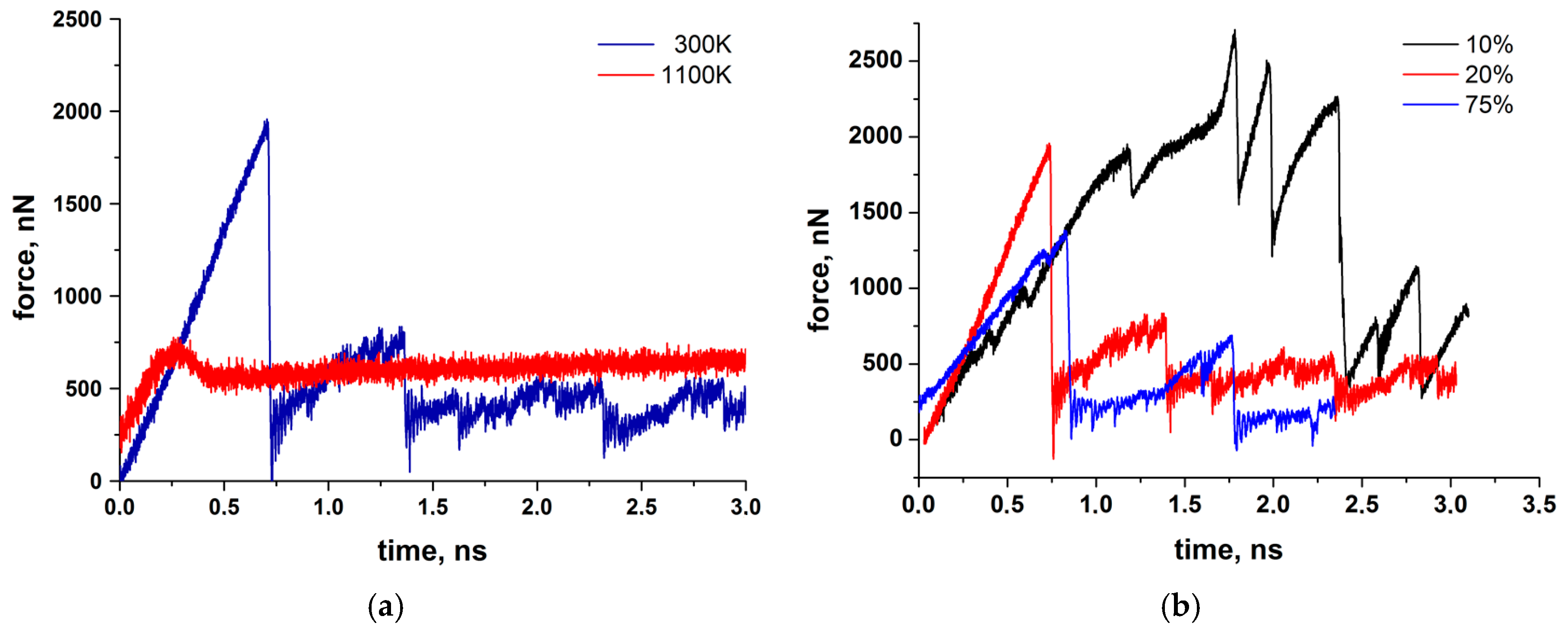
Figure 7), showing unstable and initially high friction forces at 300 K. Also shown in Figure 7, performing the simulation at 1100 K (flash temperature) yields much lower reaction forces and smooth sliding behavior. From this we can conclude that the reduction of friction observed experimentally for the silica-based tribofilm at high values of the product of pressure and sliding velocity [13] may be due to flash temperatures occurring at the carbon fiber contact sites of the composite. Whereas the simulation shown in 
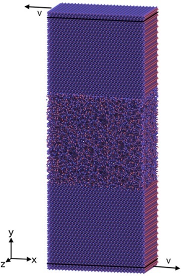
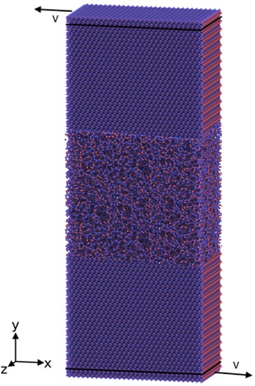
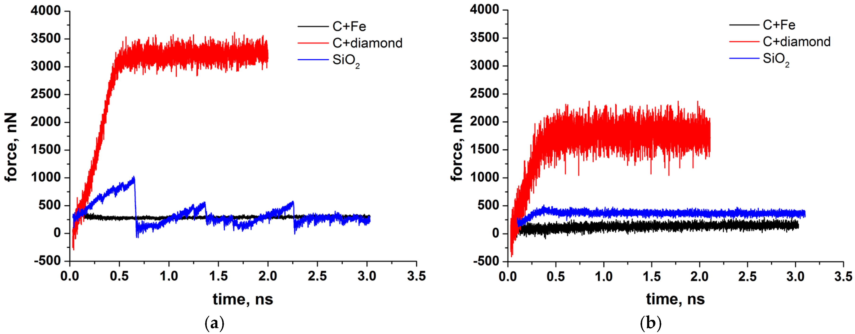
Figure 7a was performed without external pressure, a more realistic simulation result with external pressure is presented in Figure 11a at 300 K and Figure 11b at 1100 K.
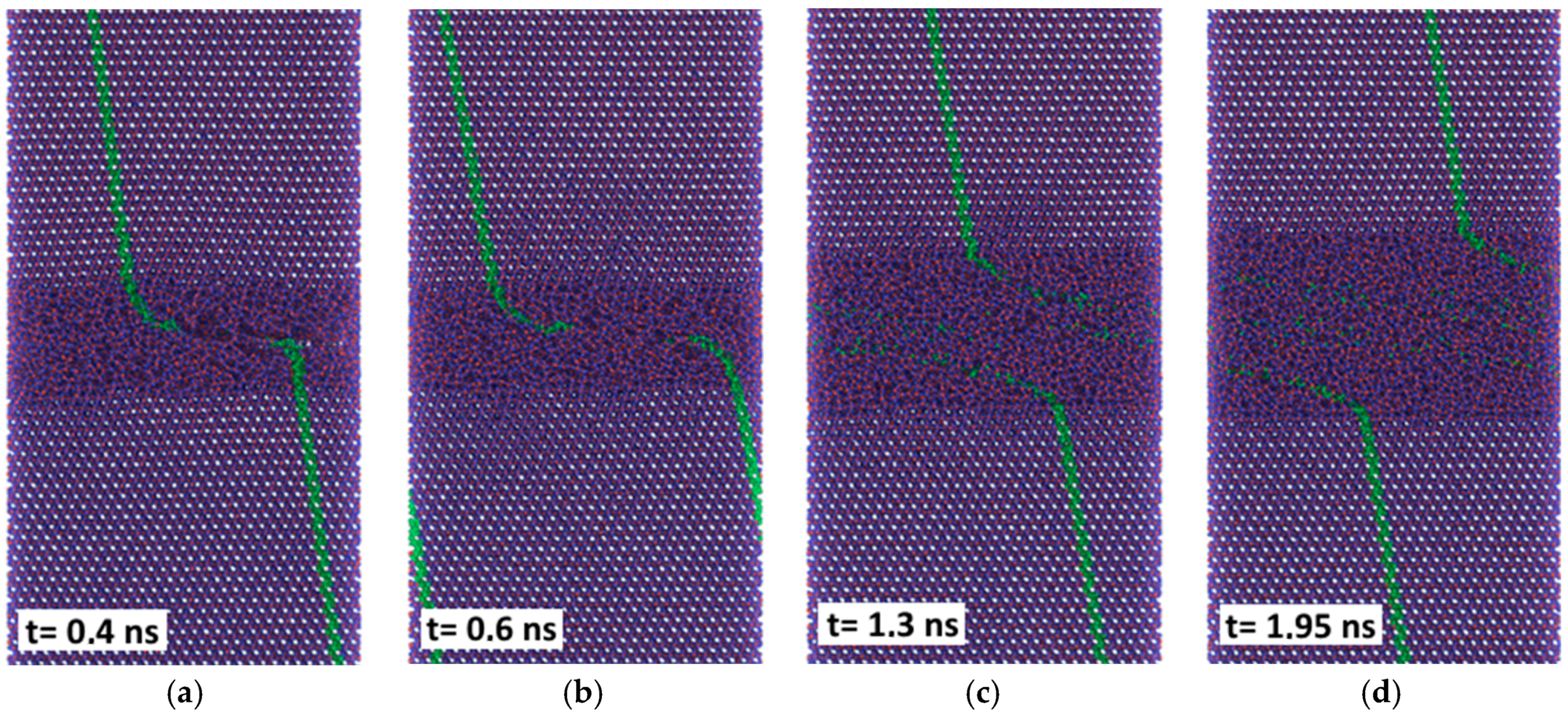
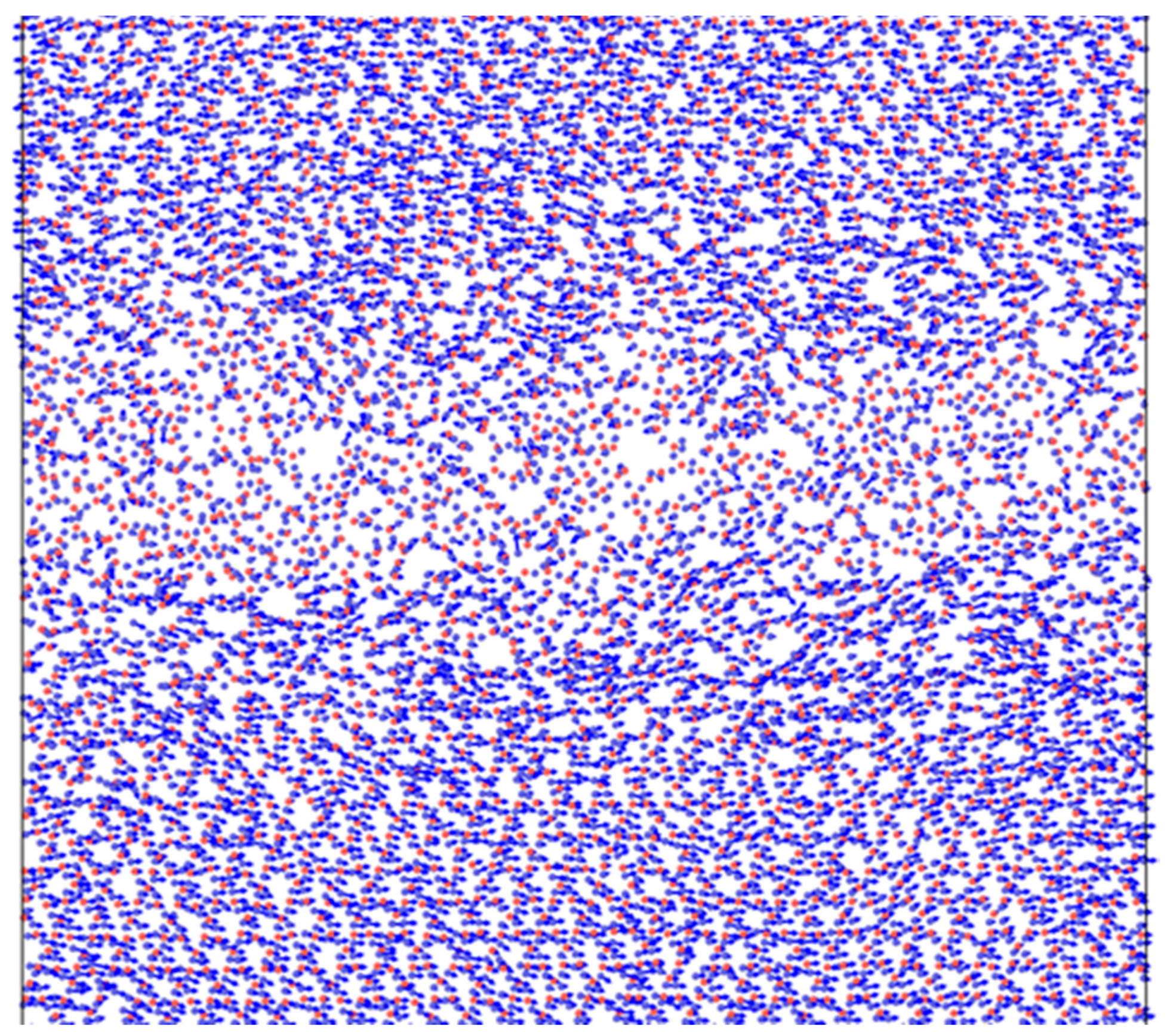
With applied pressure the friction forces of the amorphous silica layer at 300 K are reduced considerably (compare Figure 11a and 
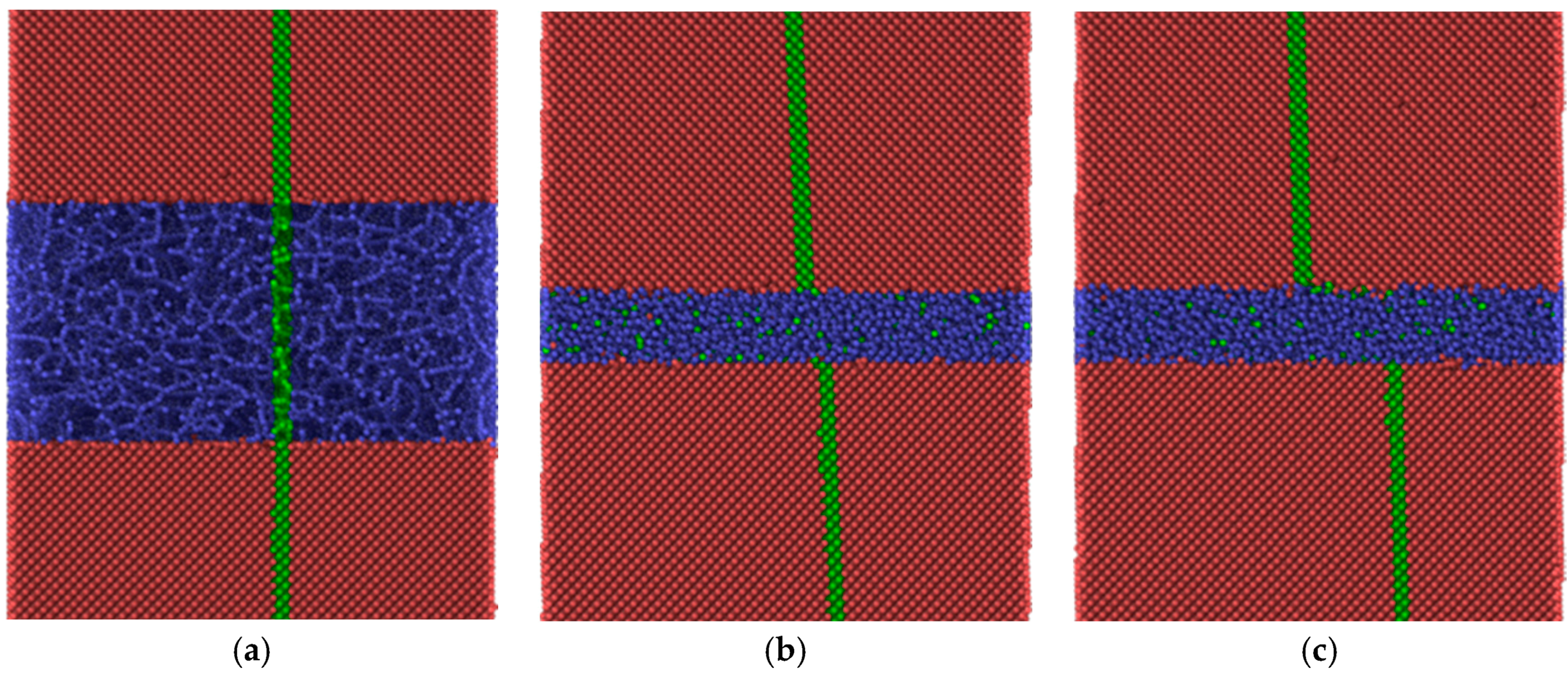
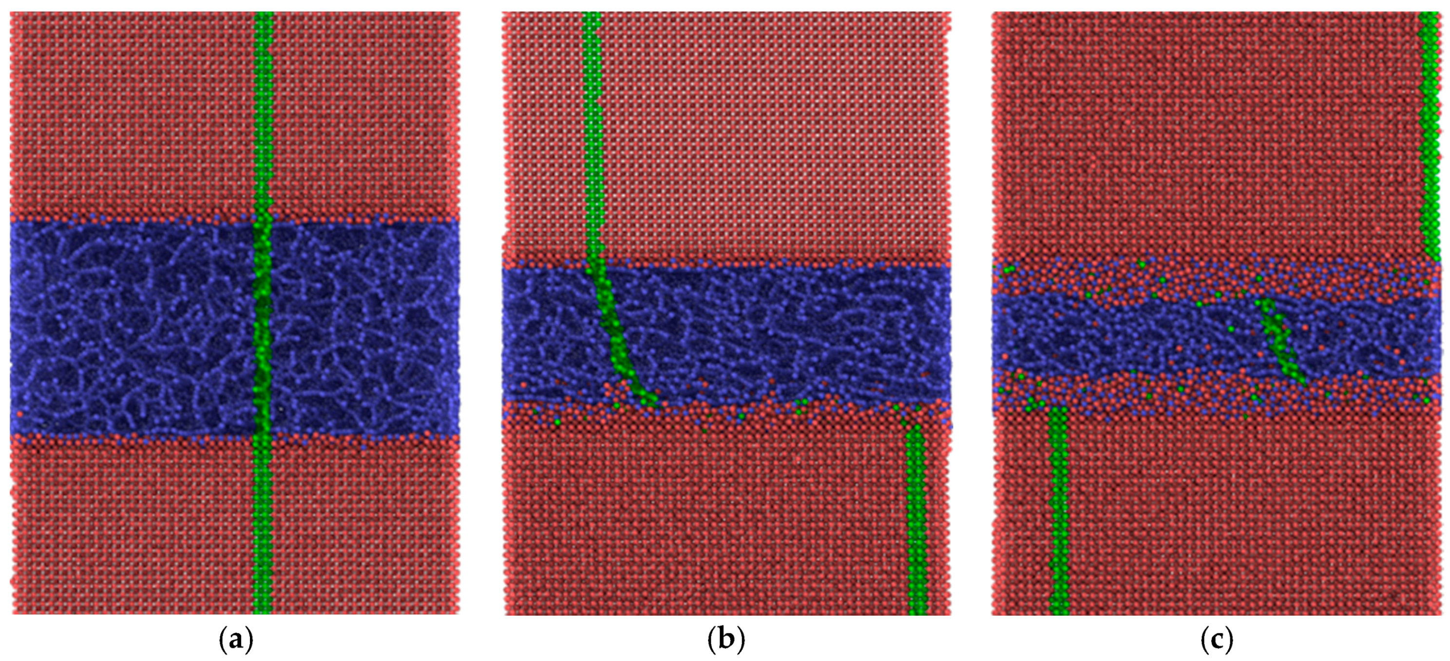
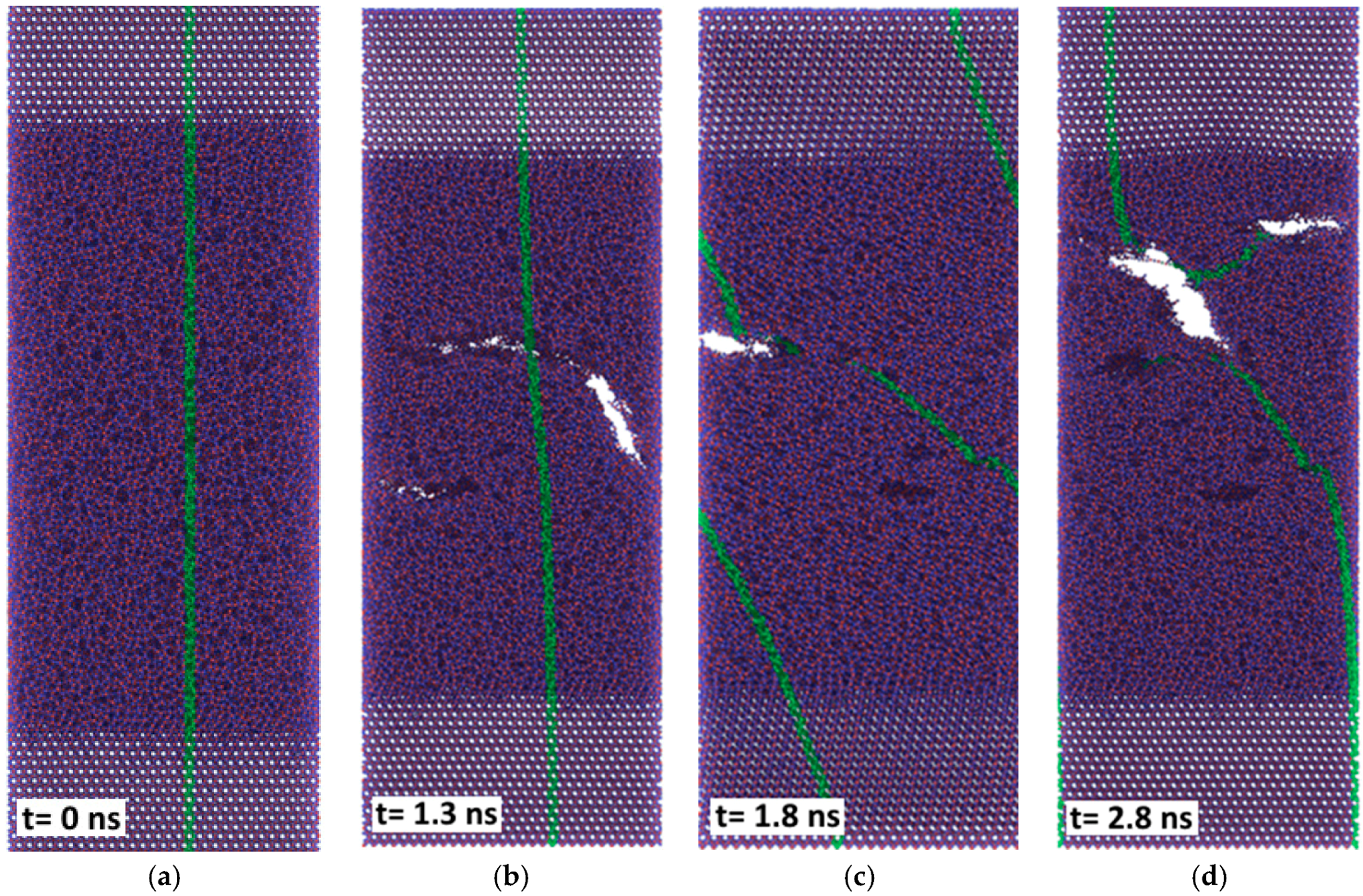
Figure 7), although the sliding remains unstable. The stick-slip type of movement correlates with the formation of the nano-sized rollers which either are linked to the substrates (sticking phase) or can roll along the interface (slipping phase). Thus, under certain conditions, pure silica films may also provide low friction at room temperature.
The friction forces obtained by MD simulation for the amorphous carbon film differed considerably with the chosen substrate materials. Strong bonds between carbon atoms both within the amorphous layer and with the diamond substrate are causing high resistance forces, as shown by the red curves in Figure 11. According to Kunze et al. [
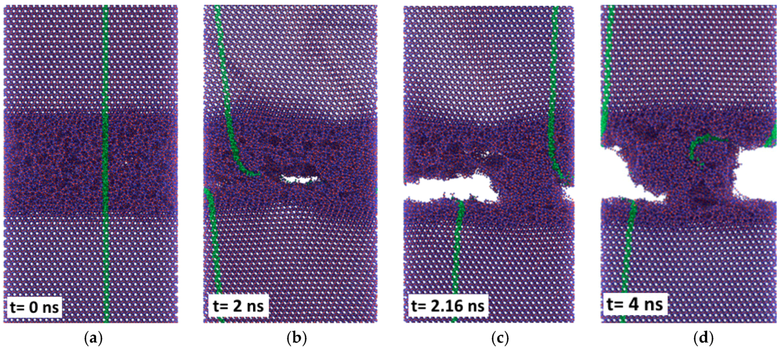
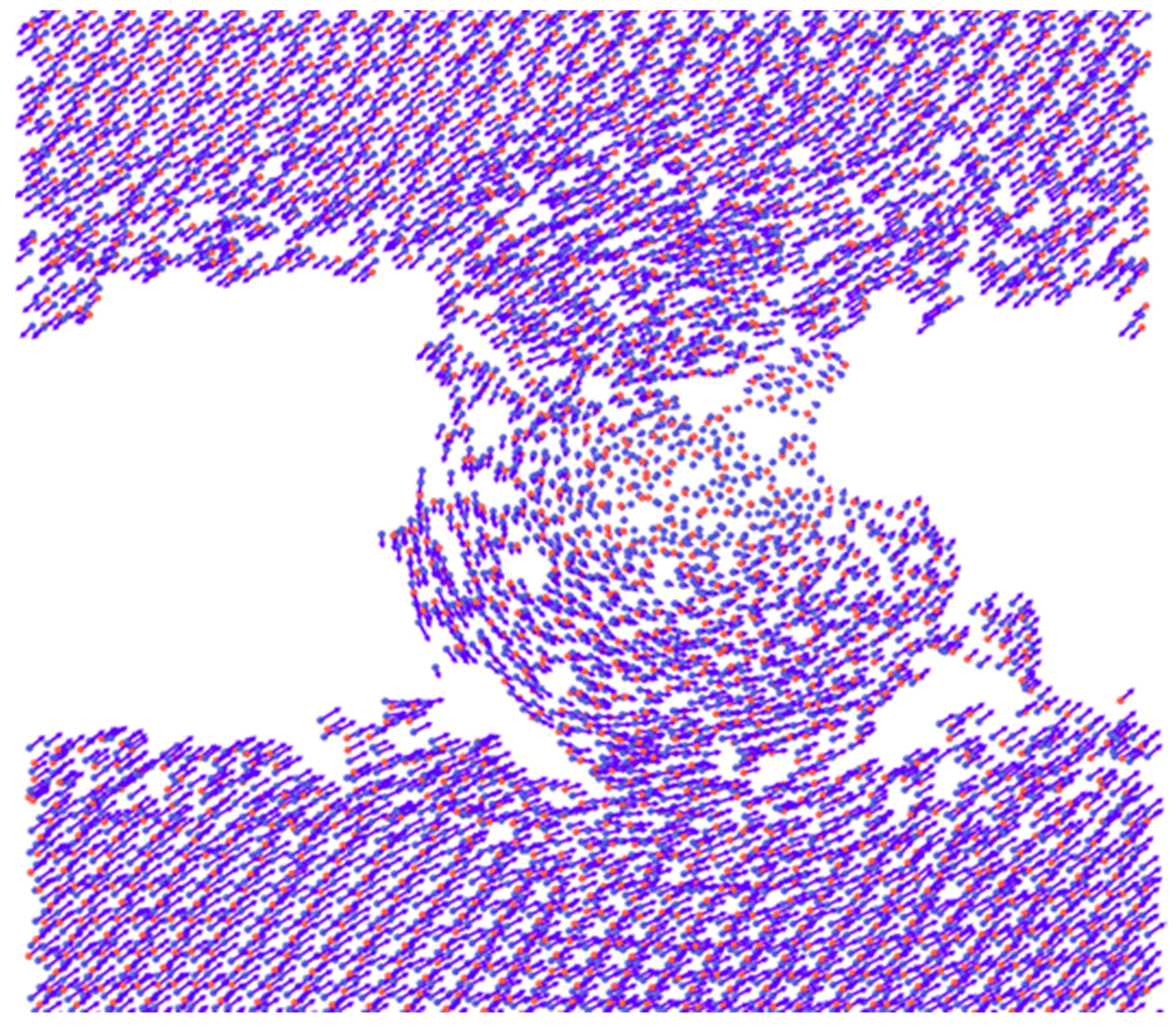
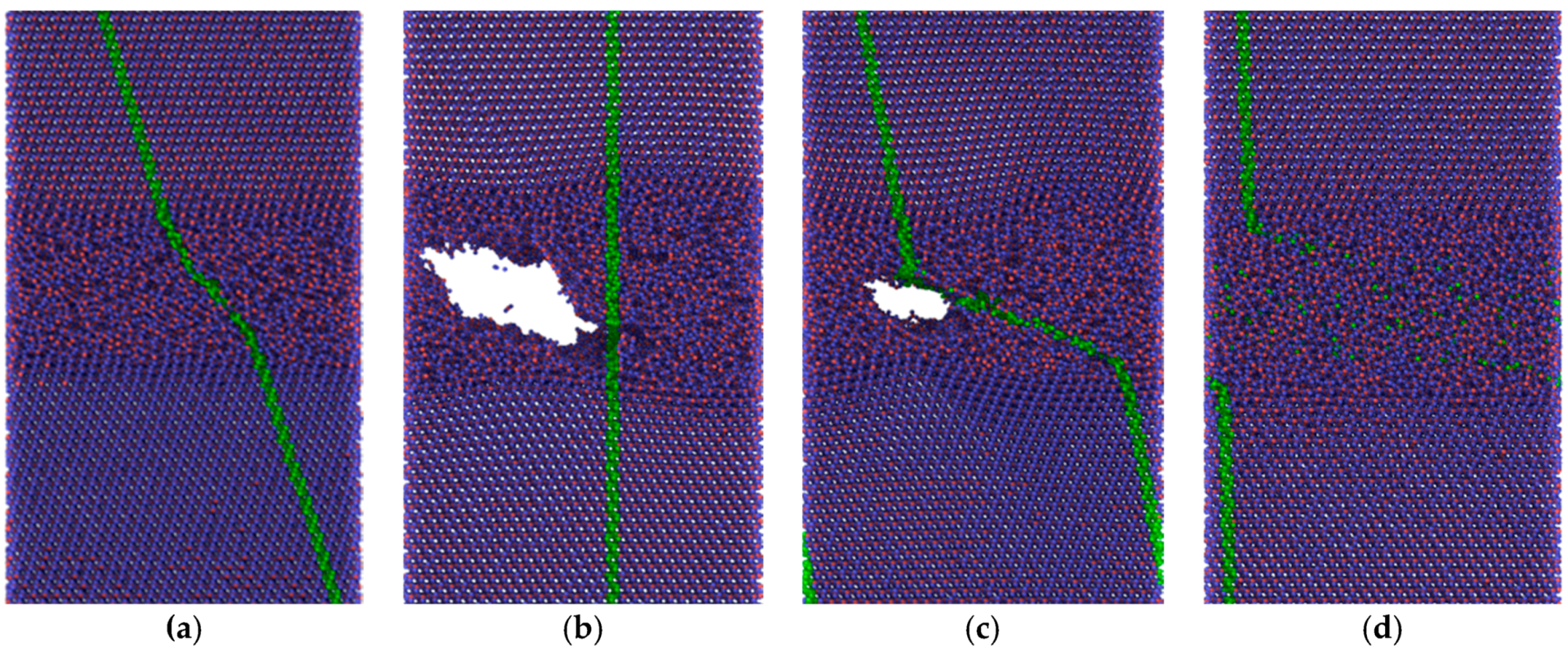
9], low friction of an amorphous carbon layer can only be expected if dangling bonds are passivated by ambient gases. Since such reactions were not considered in the present simulations, the friction forces remained high. The situation was completely different if α-Fe was chosen as the substrate material. Obviously only weak bonds exist between carbon and iron atoms. Thus, carbon atoms with broken bonds to their neighbors can move into the Fe substrate which undergoes amorphization within a certain layer, especially at the higher temperature (Figure 10c). Such behavior was also observed for other systems at ambient temperature featuring both crystalline [1,2,3,4,5] and amorphous [11] materials.

4. Materials and Methods

As briefly sketched in Section 2.1, the material systems considered within this study were modeled by a bottom-up approach using atomic potentials found in the literature. The calculations were performed on a supercomputer resource of Tomsk State University using free access software package LAMMPS [16]. LAMMPS is a classical molecular dynamics code from Sandia National Laboratory, and an acronym for Large-scale Atomic/Molecular Massively Parallel Simulator. It integrates Newton’s equations of motion for an ensemble of atoms, or molecules that interact via short- or long-range forces with a variety of initial and boundary conditions. Interatomic interaction in case of iron and diamond crystallites with carbon interlayers was described by the modified embedded atom method (MEAM) [17]. The results were compared with experimental data as well as with ab-initio calculations, such as: Structural and elastic properties of cementite, energy of interstitial C atoms in Fe lattice, and the heat of Fe–C alloy formation in L12 and B1 structures. Furthermore, the properties of pure materials within this MEAM potential (C and Fe) were also tested. To study the behavior of silica layers the three-body interatomic interaction suggested by Tersoff [18] was used.
Modified Embedded-Atom Method (MEAM) potentials [18] are an extension to the original Embedded-Atom Method (EAM) potentials by adding angular forces. It is thus suitable for modeling metals and alloys with fcc, bcc, hcp and diamond cubic structures, as well as covalently bonded materials such as silica and carbon. In the MEAM formulation, the total energy E of a system of atoms is given by:
E = i { F i ( ρ ¯ i ) + 1 2 i j ϕ i j ( r i j ) }
where F is the embedding energy which is a function of the atomic electron density ρ, and ϕ is a pair potential interaction. The pair interaction is summed over all neighbors j of atom i within the cutoff distance. As with EAM, the multi-body nature of the MEAM potential is a result of the embedding energy term.
The Tersoff approach computes a three-body Tersoff potential for the energy E of a system of atoms as:
E = 1 2 i j i V i j
V i j = 1 2 f c ( r i j ) [ f R ( r i j ) + b i j f A ( r i j ) ]
In Equation (3):
f c ( r i j ) = { 1 , r < R D 1 2 1 2 sin ( π 2 r R D ) , R D < r < R + D 0 , r > R + D f R ( r ) = A exp ( λ 1 r ) f A ( r ) = B exp ( λ 2 r )
where fR is a two-body term and fA includes three-body interactions. R and D are outer and inner cutoff radii of the order of 2.5 and 0.15 nm, respectively. The values change a bit according to the nature of the three atoms under consideration, as compiled in a table of the original paper [18]. The summations in the formula are over all neighbors j and k of atom i within a cutoff distance = R + D. This empirical interatomic potential permits the calculation of structural properties and energetics of complex systems. A new approach for constructing such potentials, by explicitly incorporating the dependence of bond order on local environment, permits an improved description of covalent materials.
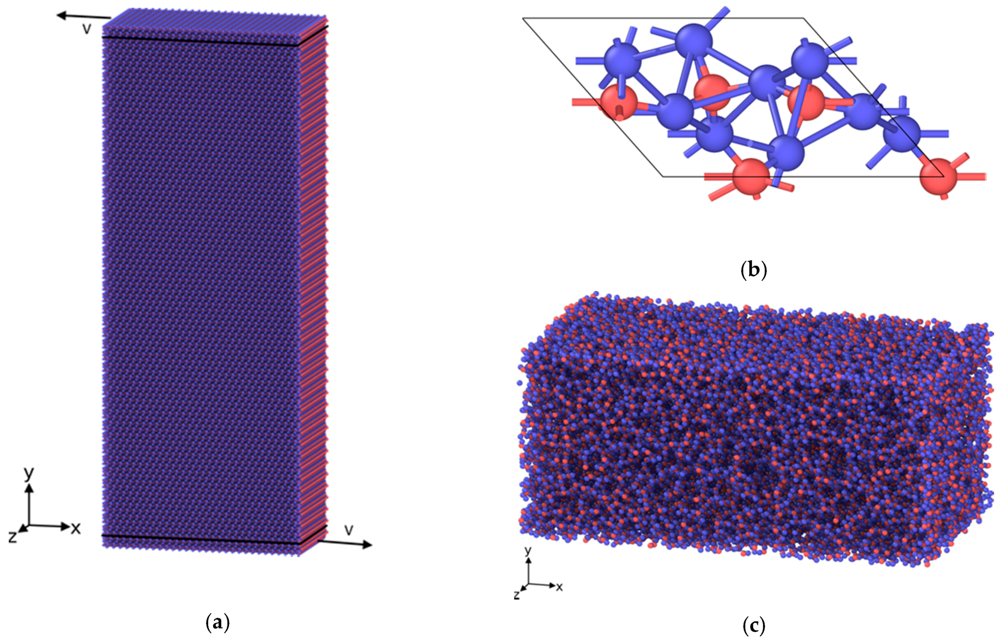
To produce the silica amorphous layer atoms belonging to the central part of the considered material volume were instantly heated up to 6000 K and then quenched to the desired temperature. In both cases the procedure of velocity rescaling was applied. In contrast to silica, the carbon amorphous layer was created directly through the procedure of random distribution of carbon atoms. After that, some of them were deleted according to the critical distance between nearest atoms, and finally the system was relaxed to the final equilibrium state.

5. Conclusions

The following fundamental knowledge supporting previous experimental findings was obtained from MD-based sliding simulations:
Amorphous tribofilms have the potential to provide low friction forces if certain prerequisites are fulfilled.
Amorphous silica films are prone to stick-slip sliding at room temperature, but provide smooth sliding at elevated temperature. This correlates with decreasing friction forces and wear rates under severe stressing conditions [13].
Amorphous carbon films can provide either high or low friction irrespective of temperature depending on the supporting substrate materials. If bound to ferritic steel, sliding is restricted to the interface between steel and amorphous carbon, and the tangential reaction forces are low.
For the latter mechanism of friction reduction, neither passivation of dangling bonds nor hybridization has to be taken into account.
Although the modeled structures are simpler than real structures, the prediction of smooth sliding of both films under conditions leading to a high flash temperature correlate well with experimental results, while the sliding behavior at moderate stressing conditions can be described better by MCA modeling.

Acknowledgments

Financial support for this work was obtained from German Research Foundation contract number: OS 77/20-1. Furthermore, a sojourn of one author (Andrey I. Dmitriev) was financed by BAM in 2014. Andrey I. Dmitriev also thanks the financial support of the RSF research project No. 14-19-0718 and the Tomsk State University Academic D.I. Mendeleev Fund Program.

Author Contributions

Anton Yu. Nikonov and Andrey I. Dmitriev conceived and designed the modeling tasks; Anton Yu. Nikonov performed the modeling; Anton Yu. Nikonov and Andrey I. Dmitriev analyzed the data; Werner Österle wrote the paper.

Conflicts of Interest

The authors declare no conflict of interest.

References

  1. Kim, H.J.; Kim, W.K.; Falk, M.L.; Rigney, D.A. MD simulations of microstructure evolution during high- velocity sliding between crystalline materials. Tribol. Lett. 2007, 28, 299–306. [Google Scholar] [CrossRef]
  2. Karthikeyan, S.; Agrawal, A.; Rigney, D.A. Molecular dynamics simulations of sliding in a Fe–Cu tribopair system. Wear 2009, 267, 1166–1176. [Google Scholar] [CrossRef]
  3. Kim, H.J.; Karthikeyan, S.; Rigney, D.A. A simulation study of mixing atomic flow and velocity profiles of crystalline materials during sliding. Wear 2009, 267, 1130–1136. [Google Scholar] [CrossRef]
  4. Kim, H.J.; Emge, A.; Winter, R.E.; Keightley, P.T.; Kim, W.K.; Falk, M.L.; Rigney, D.A. Nanostructures generated by explosively driven friction: Experiments and molecular dynamics simulations. Acta Mater. 2009, 57, 5270–5282. [Google Scholar] [CrossRef]
  5. Zhu, P.Z.; Hu, Y.Z.; Ma, T.B.; Wang, H. Molecular dynamics study on friction due to ploughing and adhesion in nanometric scratching process. Tribol. Lett. 2011, 41, 41–46. [Google Scholar] [CrossRef]
  6. Morita, Y.; Onodera, T.; Suzuki, A.; Shanoun, R.; Koyama, M.; Tsuboi, H.; Hatakeyama, N.; Endou, A.; Takaba, H.; Kubo, M.; et al. Development of a new molecular dynamics method for tribochemical reaction and its application to formation dynamics of MoS2 tribofilm. Appl. Surf. Sci. 2008, 254, 7618–7621. [Google Scholar] [CrossRef]
  7. Theiler, G.; Gradt, T.; Österle, W.; Brückner, A.; Weihnacht, V. Friction and endurance of MoS2/ta–C coatings produced by laser arc deposition. Wear 2013, 297, 791–801. [Google Scholar] [CrossRef]
  8. Pastewka, L.; Moser, S.; Moseler, M. Atomistic insights into the running-in, lubrication, and failure of hydrogenated diamond-like carbon coatings. Tribol. Lett. 2010, 39, 49–61. [Google Scholar] [CrossRef]
  9. Kunze, T.; Posselt, M.; Gemming, S.; Seifert, G.; Konicek, A.R.; Carpick, R.W.; Pastewka, L.; Moseler, M. Wear, plasticity, and rehybridization in tetragonal amorphous carbon. Tribol. Lett. 2014, 53, 119–126. [Google Scholar] [CrossRef]
  10. Pastewka, L.; Moser, S.; Moseler, M. Anisotropic mechanical amorphization drives wear in diamond. Nat. Mater. 2011, 10, 34–38. [Google Scholar] [CrossRef] [PubMed]
  11. Martin, J.M.; Onodera, T.; Minfray, C.; Dassenoy, F.; Miyamoto, A. The origin of anti-wear chemistry of ZDDP. Faraday Discuss. 2012, 156, 311–323. [Google Scholar] [CrossRef] [PubMed]
  12. Zhang, G.; Häusler, I.; Österle, W.; Wetzel, B.; Jim, B. Formation and function mechanisms of nanostructured tribofilms of epoxy-based hybrid nanocomposites. Wear 2015, 342–343, 181–188. [Google Scholar] [CrossRef]
  13. Österle, W.; Dmitriev, A.I.; Wetzel, B.; Zhang, G.; Häusler, I.; Jim, B.C. The role of carbon fibers and silica nanoparticles on friction and wear reduction of an advanced polymer matrix composite. Mater. Des. 2016, 93, 474–484. [Google Scholar] [CrossRef]
  14. Sebastian, R. Advanced in-situ Measurements within Sliding Contacts. Ph.D. Thesis, Technische Universität Kaiserslautern, Kaiserslautern, Germany, 2015. [Google Scholar]
  15. Österle, W.; Dmitriev, A.I.; Gradt, T.; Häusler, I.; Hammouri, B.; Morales Guzman, P.I.; Wetzel, B.; Yigit, D.; Zhang, G. Exploring the beneficial role of tribofilms formed from an epoxy-based hybrid nanocomposite. Tribol. Int. 2015, 88, 126–134. [Google Scholar] [CrossRef]
  16. Plimpton, S.J. Fast Parallel Algorithms for Short-Range Molecular Dynamics. J. Comput. Phys. 1995, 117, 1–19. [Google Scholar] [CrossRef]
  17. Baskes, M.I. Modified embedded-atom potentials for cubic materials and impurities. Phys. Rev. B 1992, 46, 2727–2742. [Google Scholar] [CrossRef]
  18. Tersoff, J. New Empirical Approach for the Structure and Energy of Covalent Systems. Phys. Rev. B 1988, 37, 6991–7000. [Google Scholar] [CrossRef]
Figure 1. Basic elements of the MD model for SiO2; (a) Building block consisting of an SiO2 single crystal; (b) Arrangement of Si and oxygen atoms, red and blue, respectively, in the α-SiO2 structure; (c) Amorphous layer after virtual heating to 6000 K and subsequent quenching.
Lubricants 04 00024 g001
Figure 2. Structure evolution of the central fragment of silica sample with 20% amorphous layer at 300 K: (a) Initial structure and structure after (b) 2 ns, (c) 2.16 ns and (d) 4 ns. Here and further on projections of atoms on the xy plane are used for the visualization.
Lubricants 04 00024 g002
Figure 3. Structure evolution of silica sample with 75% amorphous layer at 300 K: (a) Initial structure and structure after (b) 1.3 ns, (c) 1.8 ns and (d) 2.8 ns.
Lubricants 04 00024 g003
Figure 4. Trajectories of atoms for the structure with 20% amorphous layer at 300 K.
Lubricants 04 00024 g004
Figure 5. Structure evolution of the central fragment of silica sample with 20% amorphous layer at 1100 K: Structure after (a) 0.4 ns, (b) 0.6 ns, (c) 1.3 ns and (d) 1.95 ns.
Lubricants 04 00024 g005
Figure 6. Trajectories of atoms for the structure with 20% amorphous layer at 1100 K.
Lubricants 04 00024 g006
Figure 7. Time dependence of resistance force without applied pressure (a) of the 20% amorphous silica layer at two temperatures; (b) of three different amorphous silica layers at 300 K.
Lubricants 04 00024 g007
Figure 8. Structure formation of 20% amorphous silica layer with applied pressure 4 GPa: (a) 300 K after 0.5 ns; (b) Initial structure of layer containing void; (c) Same layer after 0.5 ns with sliding simulation at 300 K; (d) Same layer (with initial void) after 2.5 ns with sliding simulation at 1100 K. Only the central fragment of the specimen containing the amorphous interlayer is shown.
Lubricants 04 00024 g008
Figure 9. Initial structure (a) and final structures after sliding simulations of amorphous carbon layer supported by diamond substrates at 4 GPa applied pressure at (b) 300 K and (c) 1100 K. t = 2.5 ns.
Lubricants 04 00024 g009
Figure 10. Initial structure (a) and final structure after sliding simulation of amorphous carbon layer supported by α-Fe substrates at 4 GPa applied pressure at (b) 300 K and (c) 1100 K. t = 2.5 ns.
Lubricants 04 00024 g010
Figure 11. Time dependencies of resistance forces for different material combinations with 4 GPa applied pressure. (a) Simulations performed at 300 K; (b) simulations performed at 1100 K.
Lubricants 04 00024 g011

