Magnetic-Field Vector Maps of Nearby Spiral Galaxies

Graduate School of Science and Engineering, Kagoshima University, 1-21-35 Korimoto, Kagoshima 890-0065, Japan
*
Author to whom correspondence should be addressed.
Galaxies 2019, 7(1), 32; https://doi.org/10.3390/galaxies7010032
Submission received: 19 December 2018
/
Revised: 1 February 2019
/
Accepted: 5 February 2019
/
Published: 11 February 2019
(This article belongs to the Special Issue The Power of Faraday Tomography)
Abstract
:We present a method for determining the directions of magnetic-field vectors in a spiral galaxy using two synchrotron polarization maps, an optical image, and a velocity field. The orientation of the transverse magnetic field is determined with a synchrotron polarization map of a higher-frequency band, and the 180°-ambiguity is solved by using a sign of Rotation Measure (RM) after determining the geometrical orientation of a disk based on an assumption of trailing spiral arms. The advantage of this method is that the direction of a magnetic vector for each line of sight throughout the galaxy can inexpensively be determined, with easily available data and simple assumptions. We applied this method to three nearby spiral galaxies using archival data obtained with a Very Large Array (VLA) to demonstrate how it works. The three galaxies have both clockwise and counterclockwise magnetic fields, which implies that none of the three galaxies is classified in a simple Axis-Symmetric type, but types of higher modes, and that magnetic reversals commonly exist.
1. Introduction
A large-scale magnetic field of 1–10 μG exists in a spiral galaxy and is generally aligned with spiral arms [1]. Cosmic-ray electrons produce synchrotron emission by spiralling around such ordered magnetic field. Consequently, synchrotron emission is polarized transversely to magnetic field. Polarization observation thus provides us with an information on magnetic orientation. However, there is 180°-ambiguity in the direction of magnetic field as far as an observation is carried out in a single-frequency band. The line-of-sight component of the magnetic field and thermal electrons make the polarization angle rotate, which is called Faraday rotation. The rotational angle is proportional to the wavelength square, and its slope is called Rotation Measure (RM), which is proportional to the integrated strength of magnetic field and thermal-electron density along the path of line of sight. Positive RM indicates that the magnetic field is directed to the observer, and negative RM indicates the opposite direction. The RM, measured with multifrequency radio-polarization observations, tells us the line-of-sight direction and strength of the magnetic field.
Morphology of magnetic fields in galaxies can be classified based on its dominant mode: Axis-Symmetric Spiral (ASS, ), Bi-Symmetric Spiral (BSS, ), and Quadri-Symmetric Spiral (QSS, ) [2]. The azimuthal changes of RM can be used to classify morphology and to solve the 180°-ambiguity [2]. Former works have shown that IC342 and M31, for example, are classified into ASS [3,4], and that M81, M33, and NGC 6946 are classified into BSS [5,6] by examining azimuthal RM changes. However, recent high-resolution observations of nearby galaxies showed that RM distribution cannot be explained with simple ASS, BSS, or QSS models [7,8]. Stepanov [9] presented models for ionized-gas and magnetic-field patterns to explore which modes exist in a magnetic field fitting observational data.
Therefore, our knowledge on magnetic-field configurations is still incomplete, though magnetic-field configurations are fundamental information on galaxies and could be related to its origin [1,10]. In this paper, we propose a new method to investigate the structure of a magnetic field based on simple assumptions. The first idea of this method originally appeared in a master’s thesis written by Anraku [11]. Section 2 describes selections of objects to apply the method, data reduction, and magnetic-field maps. Section 3 details how our method determines the direction of a magnetic-field vector. Section 4 comprises our magnetic-field vector-maps results. In Section 5, we discuss the configurations of magnetic fields, and Section 6 provides a summary.
Note that we discriminate the meanings of “orientation” and “direction” in this paper; “orientation” is defined as an angle in the range of 0°–180° with 180° ambiguity, and “direction” is defined as an angle in the range of 0°–360° without any ambiguity.
2. Data
2.1. Selection of Objects
We selected galaxies from the Nearby Galaxy Catalog (NBG) [12] with the following criteria: (1) heliocentric distance within 4–10 Mpc to cover an entire disk with a single pointing, and to map with a resolution of less than a few kpc; (2) inclination range of 30°– 60°; (3) brighter than a B magnitude of 11; and (4) observed in C and X bands with VLA and listed in Table 5 of Beck Wielebinski [13]. The selected galaxies meeting Criteria (1)–(4) were NGC 4414, NGC 4736, and NGC 6946. Table 1 lists the basic parameters of these three galaxies: name, position in equatorial co-ordinates, morphology, B-band magnitude, recession velocity, inclination, and position angle.
2.2. Data Reduction
We used Astronomical Image Processing System (AIPS) software, developed by the National Radio Astronomy Observatory (NRAO) for polarization-data reduction [14].
The basic procedure of the primary data reduction was as follows: (1) loading FITS files (AIPS task: FILLM), (2) flagging the first 10 seconds of data of each scan and spurious data (QUACK and TVFLG), (3) entering source-flux density into the source table (SU) (SETJY), (4) determining antenna-based calibration using calibrator sources (VLAPROCS, VLACALIB), (5) determining source-flux densities (GETJY), (6) applying calibration using the solution table (SN) (VLACLCAL), (7) applying D-term calibration (PCAL), and (8) correcting phase difference between right and left polarizations (RIDIF). Thus, visibility data were calibrated in this primary reduction.
After primary data reduction, we made images of Stokes I, Q, and U by applying the IMAGR task to the visibility data. Since the obtained maps have different pointing centers and fields of view depending on frequency, we aligned image co-ordinates using the HGEOM task. Finally, polarization angle and polarization intensity P were calculated with and , respectively, using the COMB task.
2.3. Magnetic-Field Maps
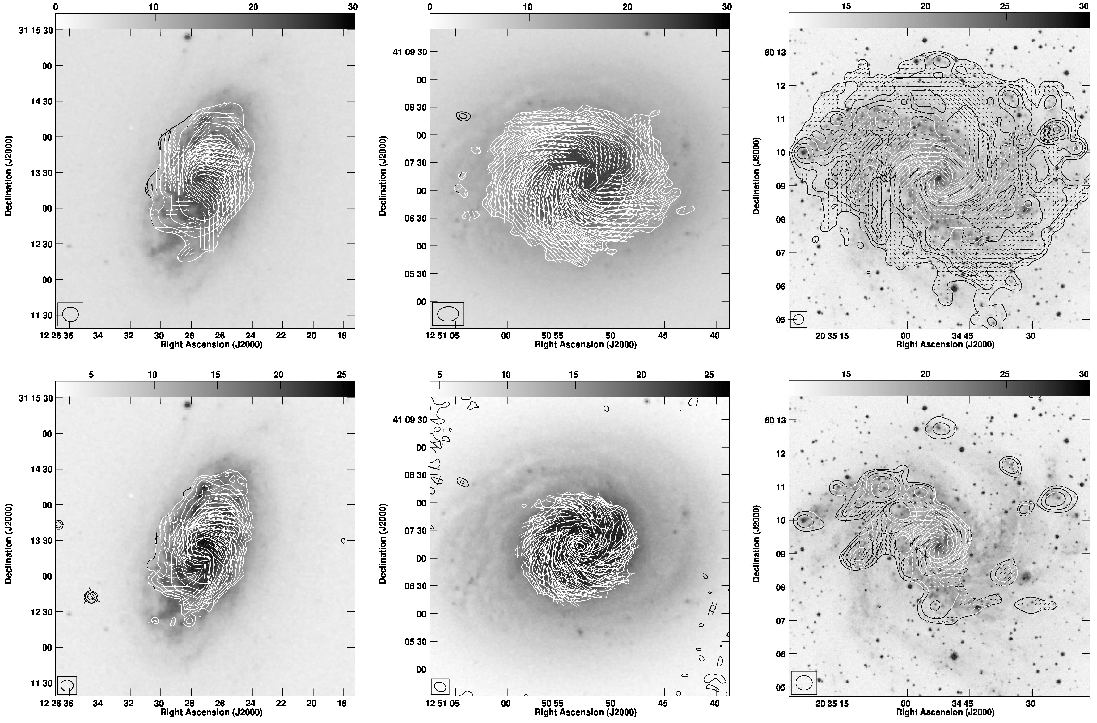
Maps of the obtained magnetic fields for the three galaxies are shown in Figure 1. Since the polarization angle (orientation of electric field) of synchrotron emission is perpendicular to the orientation of magnetic field , Figure 1 shows maps, which were obtained by rotating the polarization angle by as . Parameters of the obtained maps are listed in Table 2, where name, observation date, frequency, array configuration, size, and position angle of the synthesized beam, and root mean square (RMS) noise levels in Stokes I, Q, and U maps can be referred. Two maps in two different bands are shown for individual galaxies, and it can be seen that the orientations of change between two bands because of the Faraday rotation. Maps of higher frequency are closer to the intrinsic magnetic fields since Faraday rotation is smaller for higher frequency. Polarization angles were calculated only for areas where Stokes I has a Signal-to-Noise (S/N) ratio of more than , and polarization intensity P has S/N of more than . RMS noise level in P is also listed in Table 2.
3. Method for Making Magnetic-Vector Maps
Since the maps shown in Figure 1 present magnetic-field orientations but not directions, magnetic vectors have 180°-ambiguity. Here, we propose a new simple method for determining the direction of a magnetic-field vector at each observed point using (1) geometrical orientation of disk, (2) magnetic-field orientation, and (3) Rotation Measure (RM) sign, as follows.
(1) Disk Geometrical Orientation
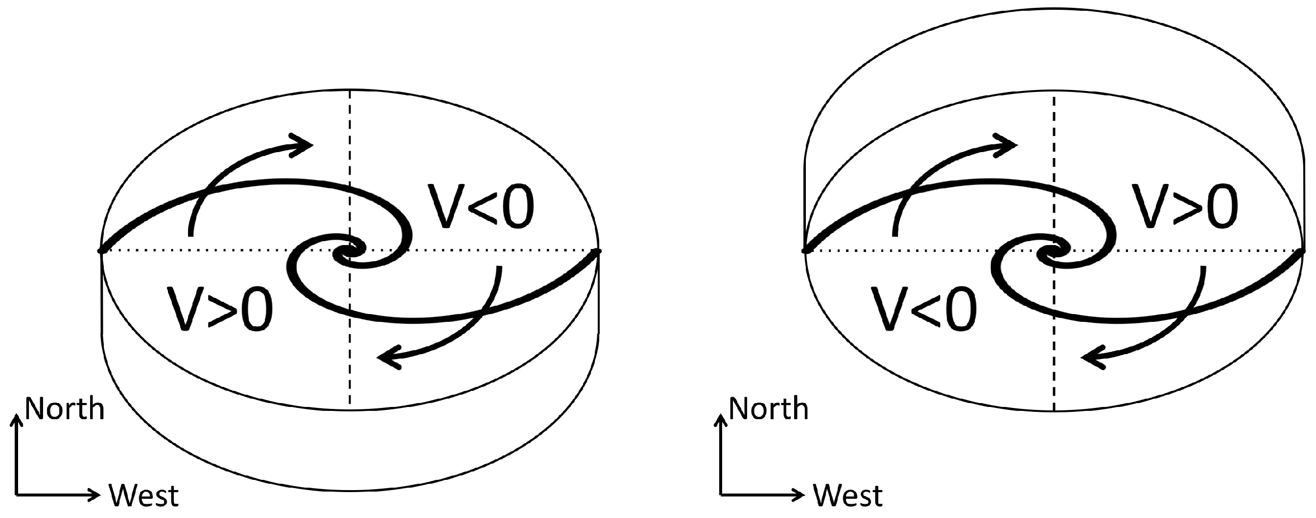
Spiral galaxies generally have trailing spiral arms but not leading ones [17]. If an image of a spiral structure and velocity field is available, we can determine the geometrical orientation of a disk on an assumption of trailing spiral arms as follows. Figure 2 shows the schematic illustrations of two galaxies with the same inclination, position angle (PA), and apparently the same spiral structure. For simplicity, let us set position angle to be 90°. These model galaxies rotate clockwise as far as they have trailing spiral arms. If radial velocity of the western side is negative, the southern side is the side nearest to the observer as shown in the left panel of Figure 2 because the model galaxy rotates in the clockwise. Similarly, if the radial velocity of the western side is positive, the northern side is the side nearest to the observer as shown in the right panel of Figure 2.
The geometrical orientation of NGC4414, one of our selected galaxies, is that the northeastern side is the near side since this galaxy rotates counterclockwise, assuming trailing spiral arms, and the southeastern side is red-shifted, consulting its velocity field [16]. Similarly, the near side of NGC 4736’s disk is the northeastern side, and that of NGC 6946 is the northwestern side.
(2) Transverse Magnetic-Field Orientation
Polarization angle changed less at higher frequency since Faraday rotation is smaller for higher frequencies. Therefore, maps at a higher frequency can be taken for transverse magnetic-field maps with 180°-ambiguity in magnetic-vector direction. A schematic illustration is shown in the left panel of Figure 3. Ideally, maps can be replaced with an intrinsic magnetic field by subtracting Faraday rotation using the RM. However, we adopted a -map of higher frequency as a transverse magnetic-field map for simplicity.
(3) Determination of Magnetic-Field-Vector Direction
Once the geometrical orientation of disk is determined as explained above, the 180°-ambiguity can be resolved by seeing the line-of-sight directions of the magnetic field, which can be derived with the RM. Let us think of the case in the left panel in Figure 2. The left panel of Figure 3 shows that orientations of the magnetic field are observationally obtained at two points. When the RM is negative at a point in the northeastern side (upper-left point), the line-of-sight component of the magnetic-field vector should be directed away from the observer (or northward), as shown with a dashed arrow in the right panel of Figure 3. Therefore, the magnetic vector has to be directed northwestward (clockwise) but not southeastward (counterclockwise). Thus, 180°-ambiguity can be resolved. In the same way, the line-of-sight component of a magnetic field at a point in the southwestern side (lower-right point) is directed toward us, and the magnetic vector is directed southeastward (clockwise). Thus, a magnetic-field vector for each line of sight through the galaxy can be obtained. However, note that this does not work if a magnetic-field vector has a small RM.
4. Results
Obtained vector maps for the three galaxies are shown in Figure 4. Vectors were plotted only at points where Stokes I is larger than , polarization intensity was larger than , and error of orientation was smaller than the Faraday rotation angle. Therefore, the number of vectors is smaller than the original polarization maps. Red and blue vectors denote clockwise and counterclockwise vectors, respectively.
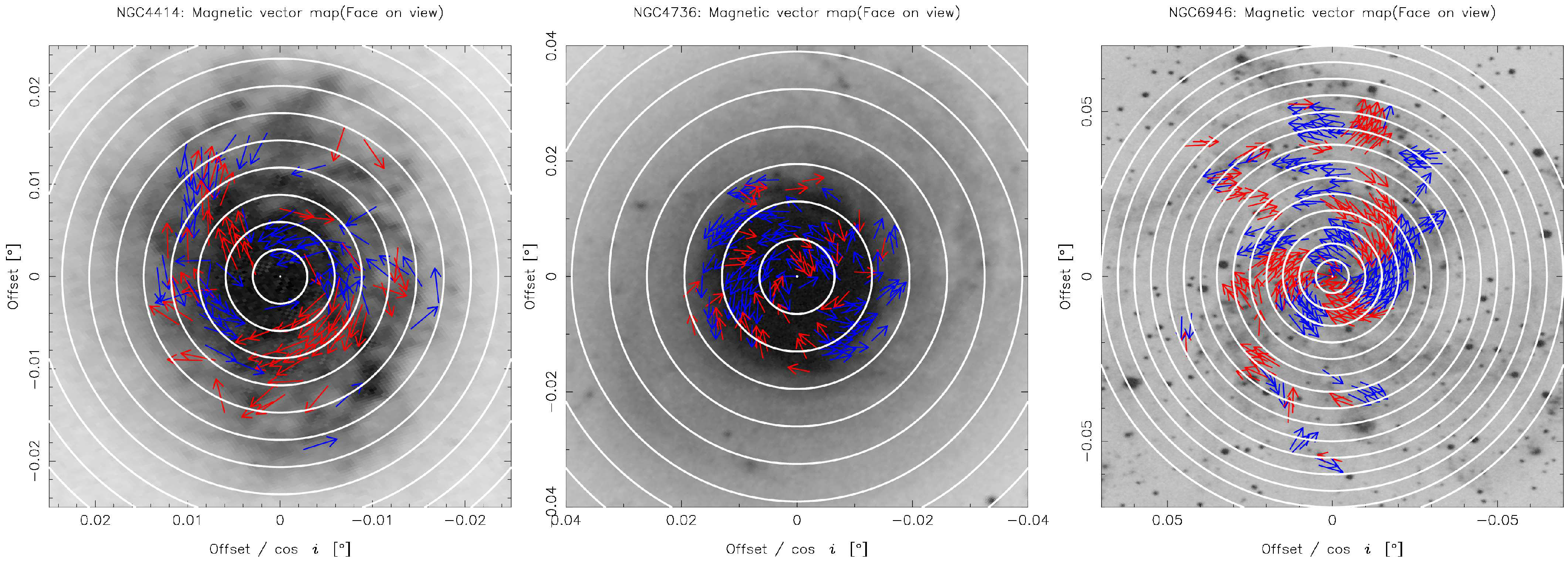
We also show face-on views of the magnetic-field-vector maps for these three galaxies in Figure 5. Circles are superposed on the maps to show the radial variations of vectors.
5. Discussion
5.1. Merits and Limits of Our Proposed Method
The merit of our proposed method is that the magnetic vector for each line of sight through the galaxy can be obtained in an inexpensive way, without any assumptions on the configurations of magnetic fields but only with simple a reasonable assumption of trailing spirals and an assumption that Faraday rotation is dominant at the disk. Optical images and velocity fields are now easily available to determine the geometrical orientation of a disk. Polarization data at two different bands are also easily available from archival systems, such as the VLA. Therefore, it is expected that our method is useful and has the potential to promote study on the configuration of magnetic fields.
However, note that this method should be used with careful consideration of its limits. The first limit is that this method should not be used in the case that the RM is small. If the RM is comparable to RMS noise, vector direction is affected by noise and cannot be determined. Therefore, we only took points where errors of orientations are smaller than the Faraday rotation angle. Because of this effect, magnetic vectors with a small RM need to be omitted.
The second limit is that face-on galaxies are not suitable for this method because the vertical component of a magnetic field in halo affects Faraday rotation. However, such an effect of a vertical magnetic field is negligible in cases when the inclination angle is larger than 15°, according to Stepanov [9]. The latter effect seems negligible for the three selected galaxies in this paper since inclination range is 30°–60°.
The third limit is that this method is suitable for studies on mean magnetic fields in galaxies, but not for studies on the total magnetic field. For the latter case of the total magnetic field, total intensity (Stokes I) should also be taken into account.
5.2. Magnetic-Field Configurations in Three Galaxies
Figure 4 and Figure 5 show that all three galaxies include both clockwise and counterclockwise vectors within them, and that there is no galaxy showing a simple ASS mode among the samples. Therefore, magnetic reversals seem to commonly exist, and higher modes, such as BSS or QSS, are not negligible in general. It should be noted that the data shown in this paper were taken only from interferometry and they generally suffer from missing flux due to a lack of a zero-spacing baseline. Since all data were obtained in a D-array whose shortest baseline was 35 m, emission from structures larger than ∼ was resolved in the C-band, and ∼ in the X-band. We assumed the same rate of the missing flux of Stokes Q and U for simplicity because we focused on proposing the method in this paper, and most emissions were concentrated within a radius of from the centers, as shown in Figure 1. Therefore, it should be noted that a component of a larger scale than was not traced in this paper, even if it exists. Details for individual galaxies are described below.
5.2.1. NGC 4414
NGC 4414 is known as an isolated flocculent spiral galaxy without strong density-wave flows. Despite such a weak density wave, a coherent magnetic field was clearly observed and its pitch angle was almost the same as that of optical spiral structures [8]. Soida et al. [8] studied the azimuthal variations of magnetic pitch angles and concluded that it can be explained with a mixture of ASS, BSS, and QSS, whose relative strengths are 1:0.6:0.3–0.5.
In our study, the obtained magnetic-vector map of NGC4414 (left panel of Figure 5) shows that clockwise and counterclockwise magnetic vectors exist. Therefore, we can conclude that the magnetic field has non-axis-symmetric components, as former work suggested. The left panel of Figure 5 shows that an annulus between the second and third circles from the center has clockwise vectors in the top-left and bottom-right regions, and has counterclockwise ones in the rest. QSS mode seems dominant in the global magnetic field since there are four reversals in a single annulus, and other annuli have the similar patterns. However, the relative strength of the magnetic-field configurations is not concluded in this paper, since more studies including careful comparisons with theoretical models should be carried out.
5.2.2. NGC 4736
NGC 4736 (M94) is known as a nearby isolated spiral galaxy with two ringlike structures. Synchrotron polarization observations showed that this galaxy has an ordered magnetic field with a spiral pattern, which is not coupled with its gaseous distribution or motion [18]. The RM is large in the northern region of the disk, and this asymmetry is thought to indicate the existence of action of a large-scale magnetohydrodynamic (MHD) dynamo.
Looking at the magnetic-vector map of this galaxy (middle panel of Figure 5), both clockwise and counterclockwise magnetic vectors can be found. This fact implies that higher modes, such as BSS (), should exist in the magnetic field. An annulus between the first and second circles has clockwise vectors in the top-right, bottom, and top-left parts, and counterclockwise ones in the others. Naively accepting these six-times changes of magnetic reversals, the sexi-symmetric spiral (SSS) mode of might be dominant in this region.
5.2.3. NGC 6946
NGC 6946 is a nearby grand-design spiral galaxy with symmetric magnetic spiral arms between optical spiral arms [19]. Beck [20] studied the magnetic field of this galaxy in detail and concluded that the two inner magnetic arms are the superposition of dynamo modes of and , and that the the inner and outer magnetic fields are amplified by turbulent gas flow and magnetorotational instability, respectively.
Our study shows that both clockwise and counterclockwise magnetic vectors exist to support the existence of higher dynamo modes, as shown in Figure 4 and Figure 5. The right panel of Figure 5 shows that annuli between the first and fifth circles contain six reversals in the azimuthal direction. This fact seems to imply that this galaxy also has an SSS magnetic field. According to Kurahara Nakanishi [21], reversals occur four times in interarm regions, and twice at spiral arms.
6. Summary
We presented a new method for deriving magnetic-vector-field maps for spiral galaxies based on simple assumptions and relatively easily available data. All data we needed were two synchrotron polarization maps obtained in two different bands, an optical image, and a velocity field, which was obtained by line observations such as HI, CO, or Hα. First, geometrical orientations of disks were determined by consulting an optical image and velocity field based on the assumptions that spiral pattern was generally trailing and that Faraday rotation was dominant in the disk. Orientations of magnetic-field lines were given by a higher-band polarization map, and the 180°-ambiguity of the magnetic-field vector was solved by checking the sign of the RM. Thus, a magnetic-field vector for each line of sight through the galaxy could be derived.
We selected three galaxies, NGC 4414, NGC 4736, and NGC 6946, to apply this method, and carried out polarization-data reduction for archival data released from the VLA. We found that all three galaxies have both clockwise and counterclockwise vectors, that no galaxy out of the three has a mode of a simple ASS magnetic field, and that higher modes, such as BSS, QSS, and SSS, seem to exist.
This method should be used with cares that face-on and edge-on galaxies should be avoided, and magnetic vectors with a small RM need to be omitted. However, our proposed method has merit in deriving a magnetic-field vector for each line of sight throughout the galaxy.
Author Contributions
Conceptualization, Methodology, and Investigation, H.N. and K.A.; Validation, H.N., K.K. and K.A.; Writing—Original Draft Preparation, H.N.; Visualization, H.N. and K.K.
Funding
This research received no external funding.
Acknowledgments
We thank the anonymous referees for their invaluable comments that have greatly improved this paper. We also thank participants to the international workshop entitled “The Power of Faraday Tomography—Towards 3D Mapping of Cosmic Magnetic Fields”, for their useful comments and discussion on our study.
Conflicts of Interest
The authors declare no conflict of interest.
References
- Sofue, Y.; Fujimoto, M.; Wielebinski, R. Global structure of magnetic fields in spiral galaxies. Annu. Rev. Astron. Astrophys. 1986, 24, 459–497. [Google Scholar] [CrossRef]
- Akahori, T.; Nakanishi, H.; Sofue, Y.; Fujita, Y.; Ichiki, K.; Ideguchi, S.; Kameya, O.; Kudoh, T.; Kudoh, J.; Machida, M.; et al. Cosmic magnetism in centimeter- and meter-wavelength radio astronomy. Publ. Astron. Soc. Jpn. 2018, 70, R2. [Google Scholar] [CrossRef]
- Graeve, R.; Beck, R. The axisymmetric spiral magnetic field in the galaxy IC 342. Astron. Astrophys. 1988, 192, 66–76. [Google Scholar]
- Sofue, Y.; Beck, R. The bisymmetric spiral magnetic field in M31. Publ. Astron. Soc. Jpn. 1987, 39, 541–546. [Google Scholar]
- Krause, M.; Beck, R.; Hummel, E. The Magnetic Field Structures in Two Nearby Spiral Galaxies-Part Two-the Bisymmetric Spiral Magnetic Field in M81. Astron. Astrophys. 1989, 217, 17. [Google Scholar]
- Beck, R. Magnetic fields and interstellar gas clouds in the spiral galaxy NGC 6946. Astron. Astrophys. 1991, 251, 15–26. [Google Scholar]
- Fletcher, A.; Beck, R.; Shukurov, A.; Berkhuijsen, E.M.; Horellou, C. Magnetic fields and spiral arms in the galaxy M51. Mon. Not. R. Astron. Soc. 2011, 412, 2396–2416. [Google Scholar] [CrossRef]
- Soida, M.; Beck, R.; Urbanik, M.; Braine, J. Magnetic fields in the absence of spiral density waves-NGC 4414. Astron. Astrophys. 2002, 394, 47–57. [Google Scholar] [CrossRef]
- Stepanov, R.; Arshakian, T.G.; Beck, R.; Frick, P.; Krause, M. Magnetic field structures of galaxies derived from analysis of Faraday rotation measures, and perspectives for the SKA. Astron. Astrophys. 2008, 480, 45–59. [Google Scholar] [CrossRef]
- Sofue, Y.; Machida, M.; Kudoh, T. The Primordial Origin Model of Magnetic Fields in Spiral Galaxies. Publ. Astron. Soc. Jpn. 2010, 62, 1191–1201. [Google Scholar] [CrossRef]
- Anraku, K. Morphological Classification of the Magnetic Field Structure with Polarization Observation Data of Nearby Galaxies. Master’s Thesis, Kagoshima University, Kagoshima, Japan, 2015. [Google Scholar]
- Tully, R.B. Nearby Galaxies Catalog; Cambridge University Press: Cambridge, UK; New York, NY, USA, 1988. [Google Scholar]
- Beck, R.; Wielebinski, R. Magnetic Fields in Galaxies. In Planets, Stars and Stellar Systems: Volume 5: Galactic Structure and Stellar Populations; Springer: Dordrecht, The Netherlands, 2013; pp. 642–723. [Google Scholar]
- Greisen, E.W. Recent Developments in Experimental AIPS. In Astronomical Data Analysis Software and Systems VII; Astronomical Society of the Pacific: San Francisco, CA, USA, 1998; Volume 145. [Google Scholar]
- De Vaucouleurs, G.; De Vaucouleurs, A.; Corwin, H.G., Jr.; Buta, R.J.; Paturel, G.; Fouqué, P. Third Reference Catalogue of Bright Galaxies. Volume I: Explanations and references. Volume II: Data for galaxies between 0h and 12h. Volume III: Data for galaxies between 12h and 24h; Springer: New York, NY, USA, 1991; p. 2091. [Google Scholar]
- Kuno, N.; Sato, N.; Nakanishi, H.; Hirota, A.; Tosaki, T.; Shioya, Y.; Sorai, K.; Nakai, N.; Nishiyama, K.; Vila-Vilaró, B. Nobeyama CO Atlas of Nearby Spiral Galaxies: Distribution of Molecular Gas in Barred and Nonbarred Spiral Galaxies. Publ. Astron. Soc. Jpn. 2007, 59, 117–166. [Google Scholar] [CrossRef]
- Binney, J.; Tremaine, S. Galactic Dynamics; Princeston University Press: Princeton, NJ, USA, 1987. [Google Scholar]
- Chyży, K.T.; Buta, R.J. Discovery of a Strong Spiral Magnetic Field Crossing the Inner Pseudoring of NGC 4736. Astrophys. J. Lett. 2008, 677, L17. [Google Scholar] [CrossRef]
- Beck, R.; Hoernes, P. Magnetic spiral arms in the galaxy NGC6946. Nature 1996, 379, 47–49. [Google Scholar] [CrossRef]
- Beck, R. Magnetism in the spiral galaxy NGC 6946: Mmagnetic arms, depolarization rings, dynamo modes, and helical fields. Astron. Astrophys. 2007, 470, 539–556. [Google Scholar] [CrossRef]
- Kurahara, K.; Nakanishi, H. Magnetic field line structure of a nearby galaxy. Galaxies 2018, submitted. [Google Scholar]
Figure 1.
Magnetic-orientation maps superposed on contour plots of Stokes I for NGC 4414 (left), NGC 4736 (middle), and NGC 6946 (right) in the C (top) and X (bottom) bands. Gray scale and contour images are B-band optical images taken from the Digitized Sky Survey (DSS) and images of Stokes I. Contour levels are 3, 6, 12, 24, 48, and (mJy/beam). Pixel numbers are 1024 for all images, and magnetic-field orientations are plotted every 15 pixels.

Figure 2.
Determination of nearside of disk based on assumption of trailing spiral arms.

Figure 3.
Determination of direction of magnetic-field vector based on a sign of the RM.

Figure 4.
Magnetic-field-vector maps of NGC4414 (left), NGC4736 (middle), and NGC6946 (right) obtained by applying our new method. Background gray-scale images were taken from DSS. Red and blue vectors denote clockwise and counterclockwise vectors, respectively.
Figure 4.
Magnetic-field-vector maps of NGC4414 (left), NGC4736 (middle), and NGC6946 (right) obtained by applying our new method. Background gray-scale images were taken from DSS. Red and blue vectors denote clockwise and counterclockwise vectors, respectively.

Figure 5.
Face-on views of magnetic-field-vector maps of NGC 4414 (left), NGC 4736 (middle), and NGC 6946 (right), superposed on optical B-band images taken from DSS. Each image was rotated by position angle and horizontally enlarged by 1/. Circles are overlaid at 500 pc intervals.
Figure 5.
Face-on views of magnetic-field-vector maps of NGC 4414 (left), NGC 4736 (middle), and NGC 6946 (right), superposed on optical B-band images taken from DSS. Each image was rotated by position angle and horizontally enlarged by 1/. Circles are overlaid at 500 pc intervals.


Table 1.
Basic Parameters of Samples.
| Name | R.A. | Dec. | Morph. | B | D | inc. | PA |
|---|---|---|---|---|---|---|---|
| [Mpc] | [°] | [°] | |||||
| (1) | (2) | (3) | (4) | (5) | (6) | (7) | (8) |
| NGC4414 | +31°13′29″ | SA(rs)c | 10.81 | 9.7 | 50 | 154 | |
| NGC4736 | +41°07′10″ | (R)SA(r)ab | 8.80 | 4.3 | 33 | 119 | |
| NGC6946 | +60°09′15″ | SAB(rs)bc | 7.92 | 5.5 | 42 | 242 |
Table 2.
Information of VLA archive data.
| Name | Date | Frequency | Array | Beam Size | BPA | ΔI | ΔQ | ΔU | ΔP |
|---|---|---|---|---|---|---|---|---|---|
| [GHz] | [(″)2] | [°] | [mJy/beam] | ||||||
| (1) | (2) | (3) | (4) | (5) | (6) | (7) | (8) | (9) | (10) |
| NGC4414 | 1995/06/03 | 4.8851 | D | 84 | 0.095 | 0.014 | 0.013 | 0.009 | |
| 1995/06/04 | 8.4149 | D | 85 | 0.011 | 0.012 | 0.010 | 0.007 | ||
| NGC4736 | 2007/04/17 | 4.8851 | D | 0.016 | 0.016 | 0.008 | 0.008 | ||
| 2007/04/17 | 8.4351 | D | 65 | 0.018 | 0.019 | 0.015 | 0.011 | ||
| NGC6946 | 1991/03/23 | 4.8851 | D | 0.039 | 0.012 | 0.012 | 0.001 | ||
| 1991/04/01 | |||||||||
| 1995/04/13 | 8.4149 | D | 89 | 0.063 | 0.002 | 0.017 | 0.015 | ||
| 1995/04/20 | |||||||||
(1) Name of galaxy, (2) Date of observation, (3) Observation frequency, (4) Array, (5) Synthesized beam size (Major axis × Minor axis), (6) Position angle of synthesized beam, (7) (8) (9) RMS noise levels in Stokes I, Q, and U, respectively, (10) RMS noise in Polarization intensity P.
© 2019 by the authors. Licensee MDPI, Basel, Switzerland. This article is an open access article distributed under the terms and conditions of the Creative Commons Attribution (CC BY) license (http://creativecommons.org/licenses/by/4.0/).
Share and Cite
MDPI and ACS Style
Nakanishi, H.; Kurahara, K.; Anraku, K. Magnetic-Field Vector Maps of Nearby Spiral Galaxies. Galaxies 2019, 7, 32. https://doi.org/10.3390/galaxies7010032
AMA Style
Nakanishi H, Kurahara K, Anraku K. Magnetic-Field Vector Maps of Nearby Spiral Galaxies. Galaxies. 2019; 7(1):32. https://doi.org/10.3390/galaxies7010032
Chicago/Turabian StyleNakanishi, Hiroyuki, Kohei Kurahara, and Kenta Anraku. 2019. "Magnetic-Field Vector Maps of Nearby Spiral Galaxies" Galaxies 7, no. 1: 32. https://doi.org/10.3390/galaxies7010032
Note that from the first issue of 2016, this journal uses article numbers instead of page numbers. See further details here.