Modelling of Temperature Field and Stress–Strain State of the Workpiece with Plasma Coatings during Surface Grinding


1
Odessa National Polytechnic University (ONPU), Schevchenko av. 1, 65044 Odessa, Ukraine
2
SaTCIP Publisher Ltd., 36210 Vrnjačka Banja, Serbia
*
Author to whom correspondence should be addressed.
Machines 2019, 7(1), 20; https://doi.org/10.3390/machines7010020
Submission received: 29 December 2018
/
Revised: 14 March 2019
/
Accepted: 17 March 2019
/
Published: 22 March 2019
(This article belongs to the Special Issue Selected Papers from the 18th International Conference Research and Development in Mechanical Industry (RaDMI-2018))
Abstract
:Plasma coatings play a key role in surface tailoring through providing important advantages for tools during their further application. However, grinding these coatings may cause different defects such as grinding burns and cracks, structural changes to the coating material, and the destruction of adhesive contacts between the coating layer and the substrate. The reason for that is the high heat flux generated in the process of abrasive material removal due to the high friction and stresses. In order to define the optimal conditions for grinding plasma coatings, the mathematical model of the temperature thermal field and the stress–strain state during the grinding process is developed. Based on the temperature, strength, and fracture criteria, this mathematical model makes it possible to define the functional relationship between the technological characteristics of the grinding process and the conditions that provide the required quality of surface processing. The role of the structural defects that are generated while coatings are being sprayed, as well as during coating adhesion, is also considered. An algorithm developed to present the results of the modelling process enables checking if the input parameters meet the condition of zero-defect grinding of a workpiece, and determining an expected surface roughness. Input parameters include the grinding wheel geometry, its abrasive properties, the wheel speed, longitudinal and transverse motion, grinding depth, and the use of the cutting fluid. Experimental testing of this study shows the way in which the regime of the grinding process and different grinding wheel parameters influence the physical and mechanical properties of the surface layer.
1. Introduction
Spraying plasma coatings makes it possible to modify the surface layer of a tool in order to provide it with valuable properties such as hardness, wear resistance, chemical inertness, or the special electrical characteristics that are needed in a designed workpiece. Meanwhile, a large number of defects may be the result of high values of hardness and brittleness of the coating materials under the effect of thermomechanical phenomena that occur during the process of grinding. The main feature of an abrasive material removal is high heat flux energy concentrated within a small area of contact between a grinding wheel and a workpiece [1,2,3].
The number of publications reflecting the role of high heat flux energy in grinding has significantly risen in the last few decades due to the impact of temperatures and residual stresses on the operational efficiency and quality of the processed surface. The modelling and simulation of different grinding conditions have been carried out in the works presented by Rowe et al. [2], González-Santander [3], Brinksmeier et al. [4] and others. Deivanathan and Vijayaraghavan [5] studied the temperature profile for triangular, parabolic, and rectangular heat sources as well as the heat energy partition ratio in the grinding zone. Zhou et al. [6] applied a finite element simulation model to investigate the high-speed grinding of the titanium matrix composites. Dai et al. [7], Qian et al. [8], and Gu et al. [9] researched the temperature distribution and forces generated in the process of grinding various difficult-to-cut materials, such as Inconel 718, K4125, and DD6 nickel-based superalloys. Lei Zhang [10] focused on grind-hardening and the critical parameters of the austenitic and martensitic transformations of the surface layer. Usov and Batyrev [11] suggested using singular integral equations to control the quality of the processed coatings sprayed onto a surface. Li et al. [12] studied the effect of different cooling and lubrication conditions on the temperature distribution along three grinding directions. Taking into account all the research referred to in this report, further analysis of the heat transfer model of the grinding process is focused on the special characteristics of plasma coatings and various defects that would reduce the quality of the processed surface.
Analysis of the temperature field and the stress–strain state of the workpiece requires studying heat transfer in the grinding zone and the impact that various grinding conditions have on the structure and residual stresses of a coating [7,13,14,15]. Linking technological parameters with the most important criteria of the processed surface quality is an essential problem of mechanical engineering and CAD (computer-aided design) development.
The objective of this report is to build a mathematical model of the temperature thermal field and the stress–strain state for the process of grinding wear-resistant plasma coatings. This model should consider strength criteria in order to reduce the number of defects caused by processing the surface layer. Special attention should be given to the structural defects generated while coatings are being sprayed, as they tend to become the centers of possible crack formation.
2. Thermal Model of Surface Grinding
The process of abrasive material removal is followed by thermal and mechanical phenomena that affect the stress–strain state of the coating layer. The major part of the produced energy flows into the processed coating, and may cause structural changes on its surface called grinding burns. Those defects are unacceptable for further application of the tool, as they decrease the wear resistance, hardness, and fatigue strength of coatings, and lead to residual strain stresses of the surface layer [16,17].
Another common type of defect is grinding cracks, which significantly reduce the serviceability of a workpiece. The nature and intensity of the crack formation are greatly determined by the thermophysical and heat-transfer properties of the processed materials, as well as their structure, heredity from the previous technological operations, grinding regime, and the applied wheel characteristics [18,19]. If the surface layer of a tool contains grinding cracks, its fracture occurs in the areas of their concentration during service.
Debonding of a coating layer from a substrate is one more constraint that makes it inappropriate to use a workpiece after being processed. Hence, it is critically important to consider an adhesive strength in order to increase the efficiency and quality of surface grinding [20,21]. Structural defects and the porosity of the coating material should also be taken into account, as they can affect the further generation of grinding cracks.
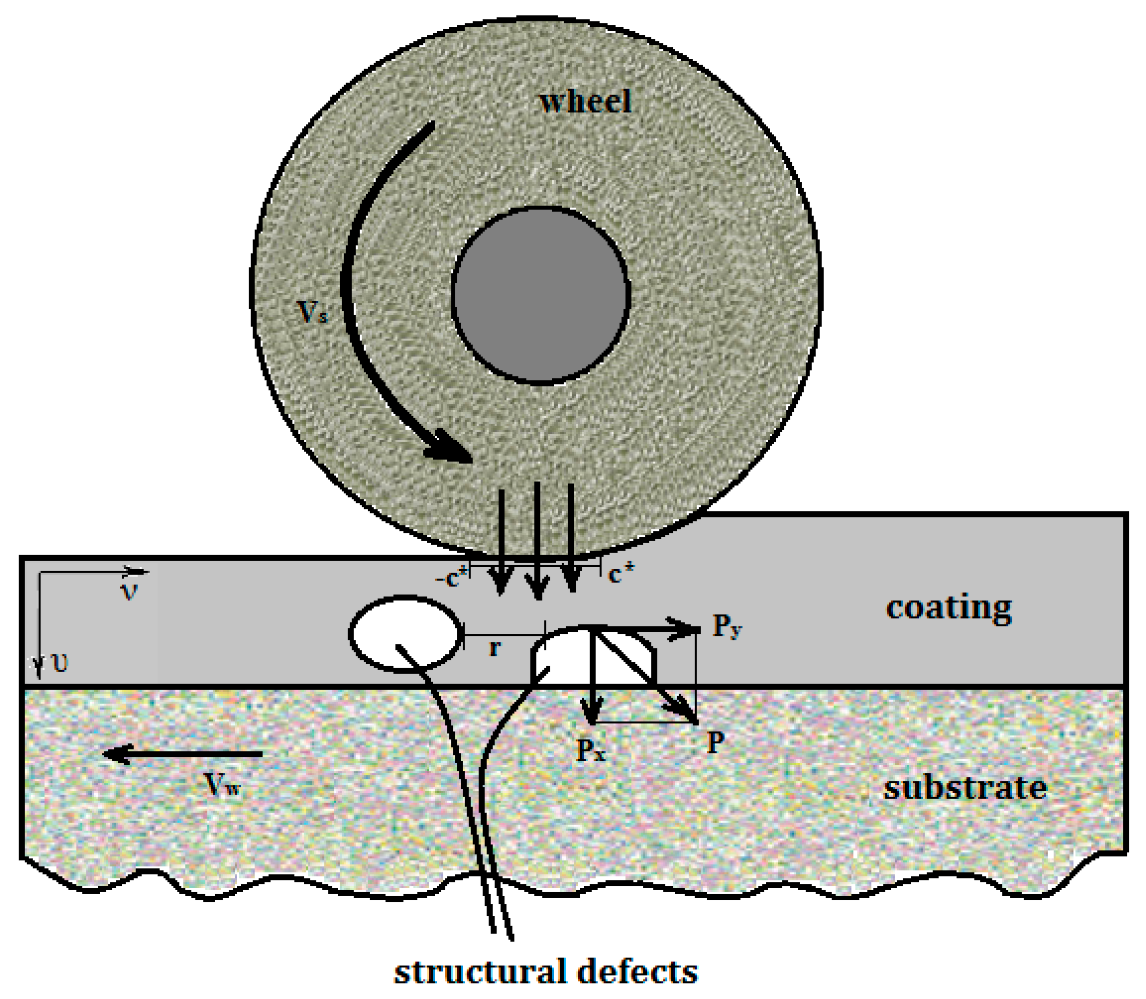
Thermomechanical analysis of the processed surface is based on a two-dimensional plane problem, since the temperature gradient and stress values studied in depth and toward the grinding wheel motion are the most important data for further investigation. During analysis of the grinding process, it is considered that the curvature of the grinding wheel within the contact zone with the workpiece does not have a significant impact on the contact interaction geometry between them. The influence of the microcracks, grain boundaries, pores, impurities, and other intrinsic defects of the surface layer are taken into account as conditional structural defects; these are shown in Figure 1.
The temperature field of the workpiece with plasma coatings during the grinding process is described with an unstable heat equation:
where is the temperature at the time and coordinates (x, y); and is thermal diffusivity of the material.
Lamé’s equation in displacements [22,23] can be used to analyse the stress–strain state of the workpiece:
where υ and ν are the components of the displacement vector at the point (x, y); is a volume deformation; is the thickness of the plasma coating; μ, G is the Lamé constant; is the Laplace operator; ; and .
The initial conditions for this problem are:
The boundary conditions of the temperature and deformation fields can be expressed as:
where is the heat flux generated as a result of the interaction between the grinding wheel and the workpiece; is the contact area length of the wheel and the processed surface; is the coating material thermal conductivity; is the heat transfer coefficient with the environment; and and are the normal and shear stresses. These boundary conditions consider the heat transferred from the surface layer within and outside the contact zone of the grinding wheel and the workpiece.
Conditions of the substrate-coating conjugation for the temperature field are:
where is the thermal conductivity of a substrate material.
For deformation fields, they are:
where υcj and υsj are the components of the displacement vector in the coating layer and the substrate, respectively; σcx and σsx are normal stresses of the coating layer and the substrate, respectively; and
and are shear stresses of the coating layer and the substrate, respectively.
Discontinuity conditions for the surface layer vary depending on the type of the structural defects. For inclusions, they can be expressed as:
For the grinding cracks, they are:
where , , , are the displacement and stress component’s jumps.
The limit equilibrium state of the processed surface layer is estimated using classical strength criteria. The fracture criteria regarding the stress intensity factor are the most appropriate for the grinding process, as they consider the physical and mechanical properties of heterogeneous materials. As soon as mode I stress intensity factor becomes equal to the critical value due to the increased local and residual stresses, grinding microcracks turn into the main fatigue crack.
Modelling of the grinding process of partially homogeneous surface layer materials (and the thermomechanical phenomena that take place during this process) is carried out using the discontinuous solutions method. This method is based on solutions that satisfy Fourier’s heat equation and Lamé’s equation all over the material, except for the boundaries of the defects. The displacement and stress fields have discontinuities of the first kind while moving through the defects boundaries, which means that the jumps of the components , , , take place.
Fourier integral transform of the function of a variable and Laplace transform of the function of a variable are applied to solve the heat transfer problem [23]. Its integral form can be expressed as:
where ; ; are the Laguerre polynomials; and is a mathematical expression considering the thermophysical properties of the coating layer, its thickness, and its initial conditions.
The stress–strain state of the surface layer is estimated using the discontinuous solutions method as well. The coating–substrate interface is considered a defect that causes discontinuities in the displacement and stress fields. Discontinuous solutions of Lamé’s equations with the set jumps of displacement and stress components are built using Trefftz functions:
where ; ; ; .
Stress values can be calculated from the equations:
Applying Fourier transform to Equations (2), (3), (6), and (7)–(11) of variables , makes it possible to obtain recurrence relations between the coating layer and the substrate stress and displacement components.
The influence of coating material heterogeneities on cracking intensity is studied through thermal stresses caused by uneven heating of the surface layer. Grinding crack formation is a result of these stresses concentrated near the defects location. To formulate the problem in mathematical terms, let us suppose that there are defects on the lines in an elastic half-plane. The stress and displacement fields have discontinuities moving through these defects:
In order to distinguish the left and the right edge of the defect, the corresponding values are marked (+) or (−). Boundary conditions (12) or (13) are applied depending on the prevailing type of the defects. Therefore, studying the thermomechanical state of the surface layer containing intrinsic defects is to solve the system of singular integral equations of either jumps of displacement components , for the grinding cracks or jumps of the stresses , in case of inclusions.
where , are the kernels reflecting the location and orientation of the defects; and parameter describes physical and mechanical properties of the coating material.
The regular integrals in Equation (25) are calculated on the basis of the Chebyshev–Gauss quadrature formulae, and the singular integrals with the Cauchy kernels can be calculated with an orthogonal polynomial method. Hence, we get an algebraic equation system with the unknown coefficients. Finally, values of stress and displacement in the surface layer can be expressed as:
where:
and is the coating defect sizes. As follows from the classical linear elasticity theory for stresses in the area, the characteristics of the stress–strain field at the tip of penny-shaped defects such as pores, foreign inclusions, and structural defects are determined by the stress intensity factor .
Thus, the stress intensity studied in the vertices of a defect long located in the depth of from the surface allows determining the limit value of heat flux that causes the growing of this defect into a main fatigue crack:
The properties and geometrical dimensions of the structural defects in a coating layer may either reduce the grinding crack growth or increase it. If the heat flux direction is parallel to an elliptical inclusion, and a linear expansion coefficient of inclusion is higher than that of base material , (i.e., ), that leads to increasing the stress intensity factor . As a result, the crack resistance of the surface layer reduces significantly. As for the microcracks, their orientation has a decisive influence on the stress intensity factor. When the crack is located within the distance of the phase boundary, maximum values of the stress intensity factor . are reached at the defects that are parallel to the boundary. When approaching to the phase boundary, . is maximum near the cracks disposed perpendicular to the boundary. The mode II stress intensity factor . is maximum at the angles close to .
Grinding wheel characteristics have a significant impact on the thermomechanical state of the surface layer [24]. The relationship between them can be defined using Equations (1) and (4), and the boundary conditions:
where is the Heaviside step function; is the Dirac delta function; is the number of grains moving through the grinding zone; is the wheel speed; is the grinding time; is the heat flux coming from the single grain; is the contact area length of the wheel and the processed surface; and is the average distance between abrasive grains.
A mathematical model of the temperature thermal field during the grinding process is based on the equations:
where is the workpiece speed; is the diameter of the grinding wheel; and is the width of the grinding wheel.
3. Analysis of Structural Defects
The structural heterogeneity of the coating layer may cause a decrease in the crack resistance. Numerous experiments have shown [25,26,27] that grinding cracks mostly occur in the area of the structural defects. Analysis based on the local fracture criterion yields the following inequality:
where is the crack resistance of the processed coating; is Young’s modulus; is the Poisson’s ratio of the coating material; is the grinding depth; is the linear expansion coefficient; and is a typical linear dimension of the structural defect. During the experiment, the parameter is defined as the size of the pores of plasma coatings.
An analysis of plasma-spraying characteristics allows adjusting the porosity of coatings and the pore size [28,29]. A number of studies have focused on the theoretical [30,31] and experimental [32,33,34,35,36,37,38,39] research of the relationship between the parameters of the plasma jet and pore-size distribution of the coated material. On the basis of the empirical results obtained in [33], it is possible to figure out that the porosity is a function of the plasma powder particles’ dimension:
where is an average particle dimension; is the ratio of interaction energy between the particle and the surface to the kinetic energy received by the particle while moving in the plasma jet; and is a coefficient considering the properties of the powder material.
Powder particles may be supposed as having a spherical shape; therefore, Function (34) can be expressed as:
where is the average diameter of the particles; is the Van der Waals interaction energy between the particle and the surface; and is the kinetic energy of the particle at the moment it reaches the coated surface.
Coefficient should consider both the cohesion of the coating material and its thermal properties. Since the thermal properties of the particle are completely described with a Biot number, a final empirical relationship between the porosity and the powder particle size can be expressed as:
where is the coefficient considering cohesion; and is the Biot number.
Therefore, the porosity of the coating layer can be determined using the characteristics of the plasma spraying process. This relationship enables defining the key feature of the coating material, as the porosity has an important impact on the thermal characteristics and microhardness of plasma coatings [37,38].
4. Results
On the basis of the presented analysis, the set of the resulting criteria can be formulated in order to determine the functional relationship between the technological parameters of the grinding process and the conditions that provide the required quality of the processed surface. Thus, the grinding depth and grinding wheel characteristics have a major influence on the cracking resistance and contact temperature during the removal of an abrasive material. The required quality of the processed surface will be provided if it is possible to figure out such grinding regimes, cooling and lubricating fluids, and wheel characteristics so that the current values of grinding temperature , heat flux , stresses and , stress intensity factor , grinding force components and do not exceed their limit values.
A system of bounding inequalities that contains temperature values and the depth of the heat spread can be expressed as:
where is the maximum value of the instantaneous temperature; and is a constant temperature component averaged over the number of abrasive grains.
Implementation of the system (37) makes it possible to avoid grinding burns, and may be used as fundamental for the grinding operation conditions design based on the Fourier criterion.
To avoid grinding cracks while processing the coating material, stresses that are formed in an intensive cooling area:
should be limited to the values:
The process of destroying adhesive contacts between the coating layer and the substrate may be avoided if an adhesive strength is greater than the stresses that destroy adhesion:
In case of a dominant influence of structural defects over the generation intensity of grinding cracks, it is necessary to use criteria based on deterministic causality among the technological parameters and properties of the defects themselves. The stress intensity factor constraint may be an example of such a criterion:
Another way is to comply a heat flux limit value by controlling technological parameters, thus preserving an equilibrium of structural defects:
Conditions of zero-defect grinding can be realised by using information about the structure of the processed material. Thus, if the structural defects are 2l long, have the prevailing number, and their arrangement is regularly close to the grinding wheel and the processed surface contact area, the criterion constraint can be expressed as the defects equilibrium condition:
The technological dimension of this formula is contained in the relation of the contact temperature value with the grinding characteristics.
These inequalities provide a link between the characteristics of the temperature and force fields and technological parameters. They determine the possible combinations of such parameters that meet the received thermomechanical criteria. Therefore, the properties of the processed material are considered, and the required quality of the surface is provided while grinding coated workpieces.
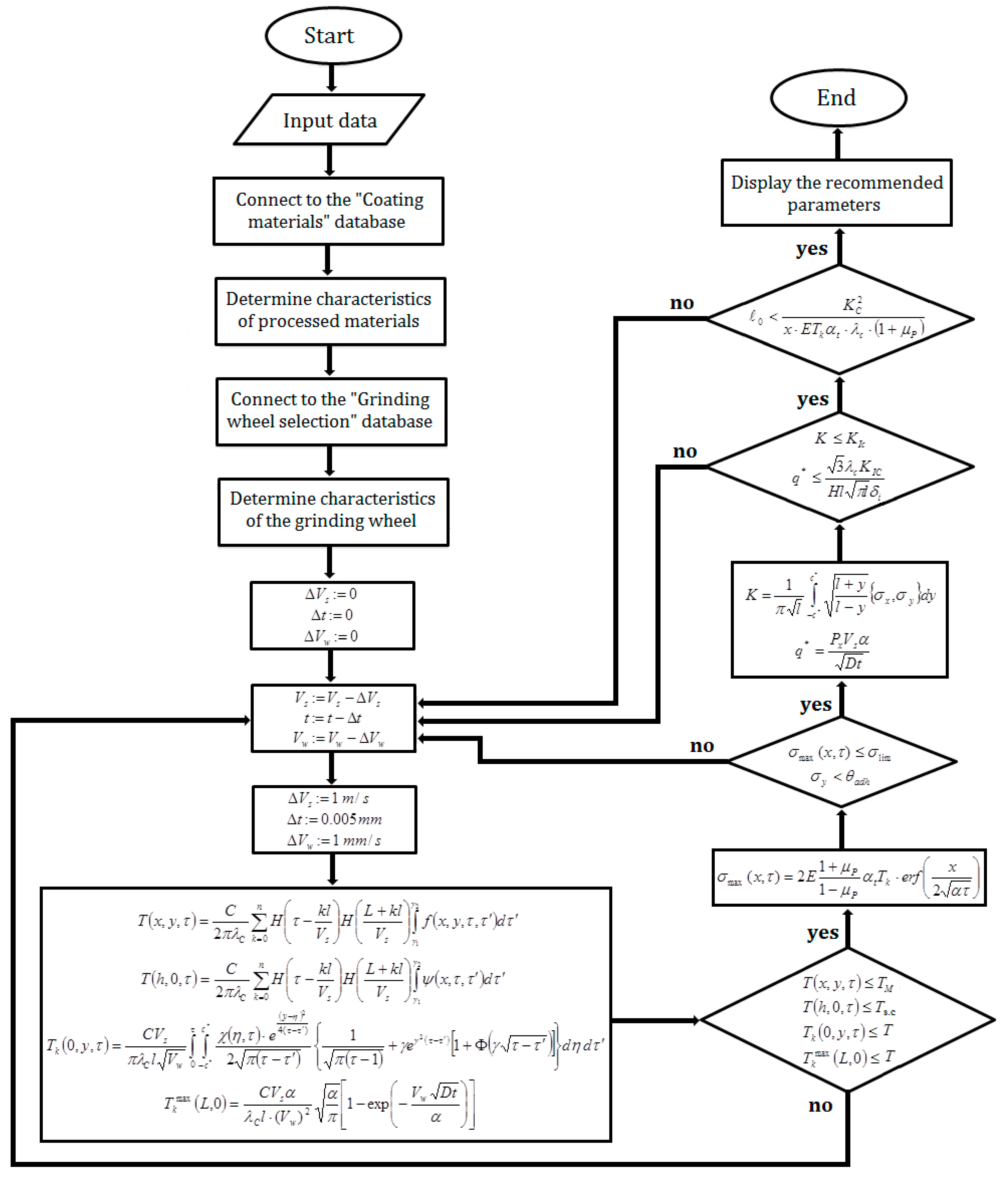
On the basis of the obtained strength and fracture criteria, an algorithm that provides the required quality of the surface processing is developed, taking into account the maximum productivity of the grinding process condition.
5. Simulation Results and their Analysis
Modelling of the temperature field of the workpiece with plasma coatings during the grinding process and the plot of temperature as a function of time are defined using numerical analysis on the procedure based on the algorithm presented in Figure 2.
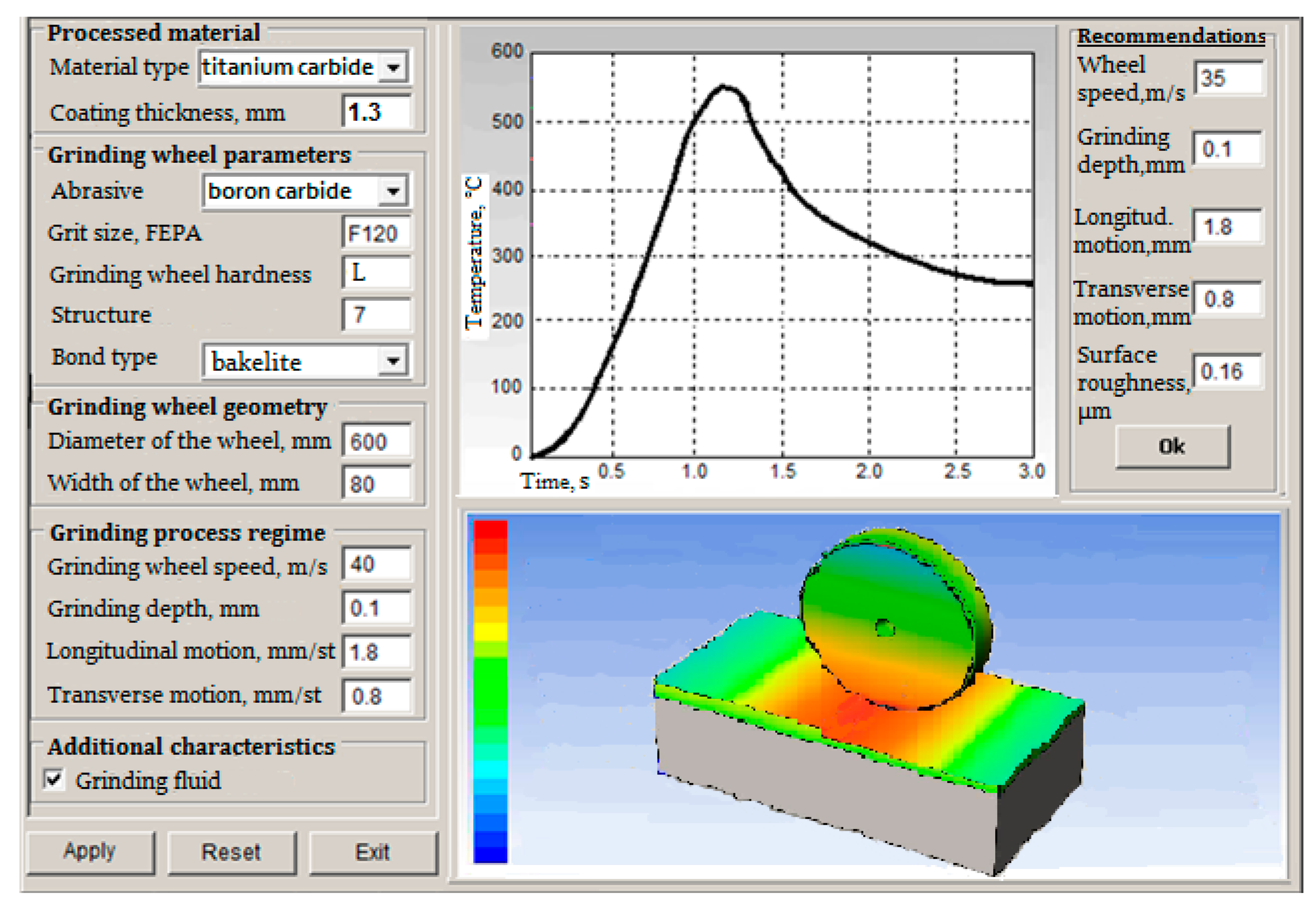
Figure 3 shows the interface of the software developed to implement the specified algorithm. To start the modelling process, the user should input the required data into the fields on the left-hand side of the interface panel and click the “Apply” button. When the data is processed and the calculations are carried out, the plot of the temperature spread in a workpiece over grinding time is shown in the right-hand window. Recommended characteristics of the grinding process, such as wheel speed, grinding depth, longitudinal and transverse motion, and an expected surface roughness of the obtained coatings, are displayed as well. If the considered input parameters meet the condition of zero-defect grinding of a workpiece, they are displayed in the window unchanged. The result of modelling the temperature thermal field spread in the workpiece with plasma coating and in the grinding wheel is displayed in a window below, where the maximum temperature is marked in red and the minimum temperature is marked in blue.
Experimental studies of grinding temperatures and cutting force are based on a set of tests. They are carried out depending on the regime of the grinding process and different grinding wheel parameters. The physical and mechanical properties of the surface layer of a coated workpiece are determined by its microhardness, the value of the residual stresses, the fracture toughness, metallographic and fractographic research on the structural changes and the fracture pattern, grinding burns’ control on acid chemical milling technology, and grinding cracks’ magnetic and color flaw detection.
6. Experimental Validation
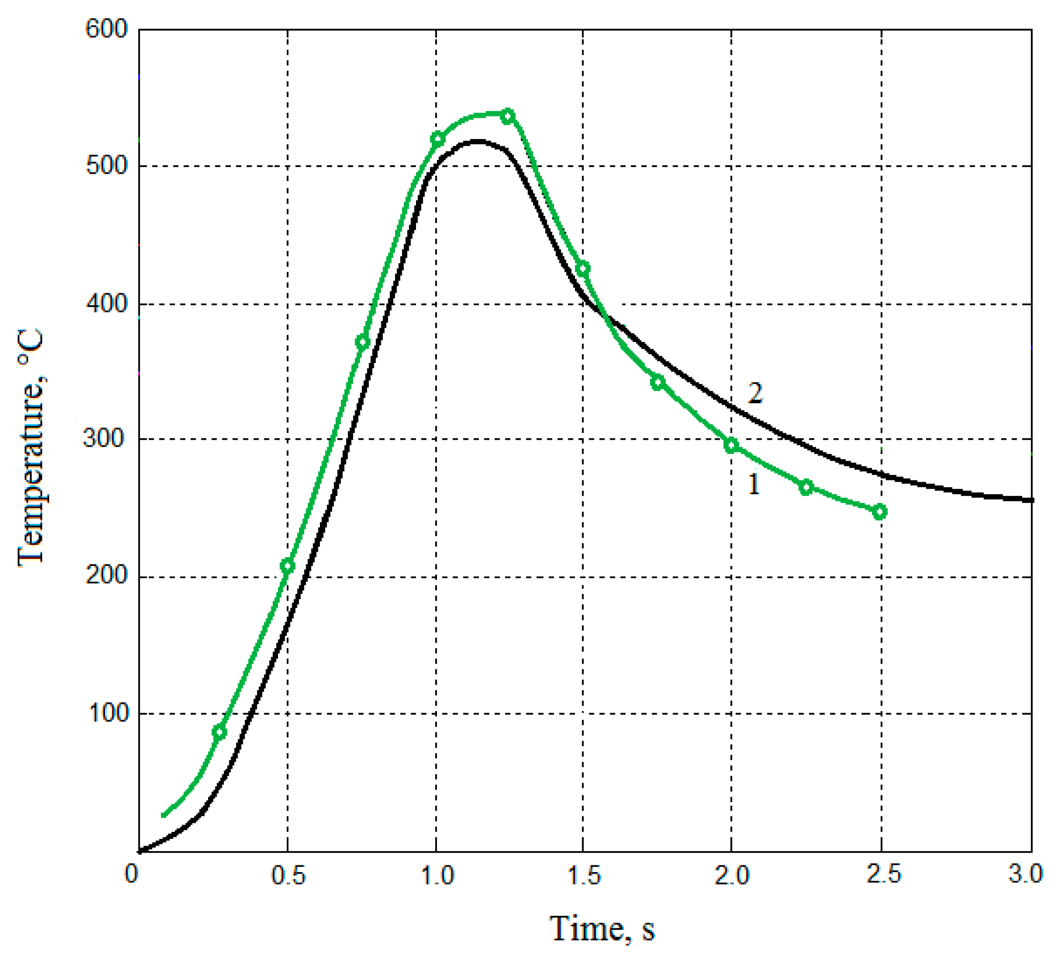
In order to validate the obtained mathematical model, experimental tests were carried out on wear-resistant plasma coatings based on titanium carbide (TiC) sprayed onto the surface of AISI 1045 steel workpieces. The coating thickness lay within 0.4–0.6 mm. Zero-defect grinding parameters were calculated using following physicomechanical characteristics: ; ; and . Figure 4 shows the experimental results of temperature spread in a workpiece over grinding time (graph 1) in comparison with the results of temperature field modelling (graph 2).
Taking into account the random size of the defects and distribution character of defects in the coating material, the probability distribution pattern of those defects should be defined. A function that describes the distribution of defect size was determined on the basis of the analysis of investigated workpiece surface microsections before the grinding operation. The obtained function defines the relationship between the dimension value and the frequency of these defects appearing in the area of contact between a grinding wheel and a workpiece. Experimental tests of defects distribution showed that the function corresponded to the normal distribution (Figure 5). The probability of fracture was calculated supposing that different defects did not interact with each other, following the weakest link hypothesis.
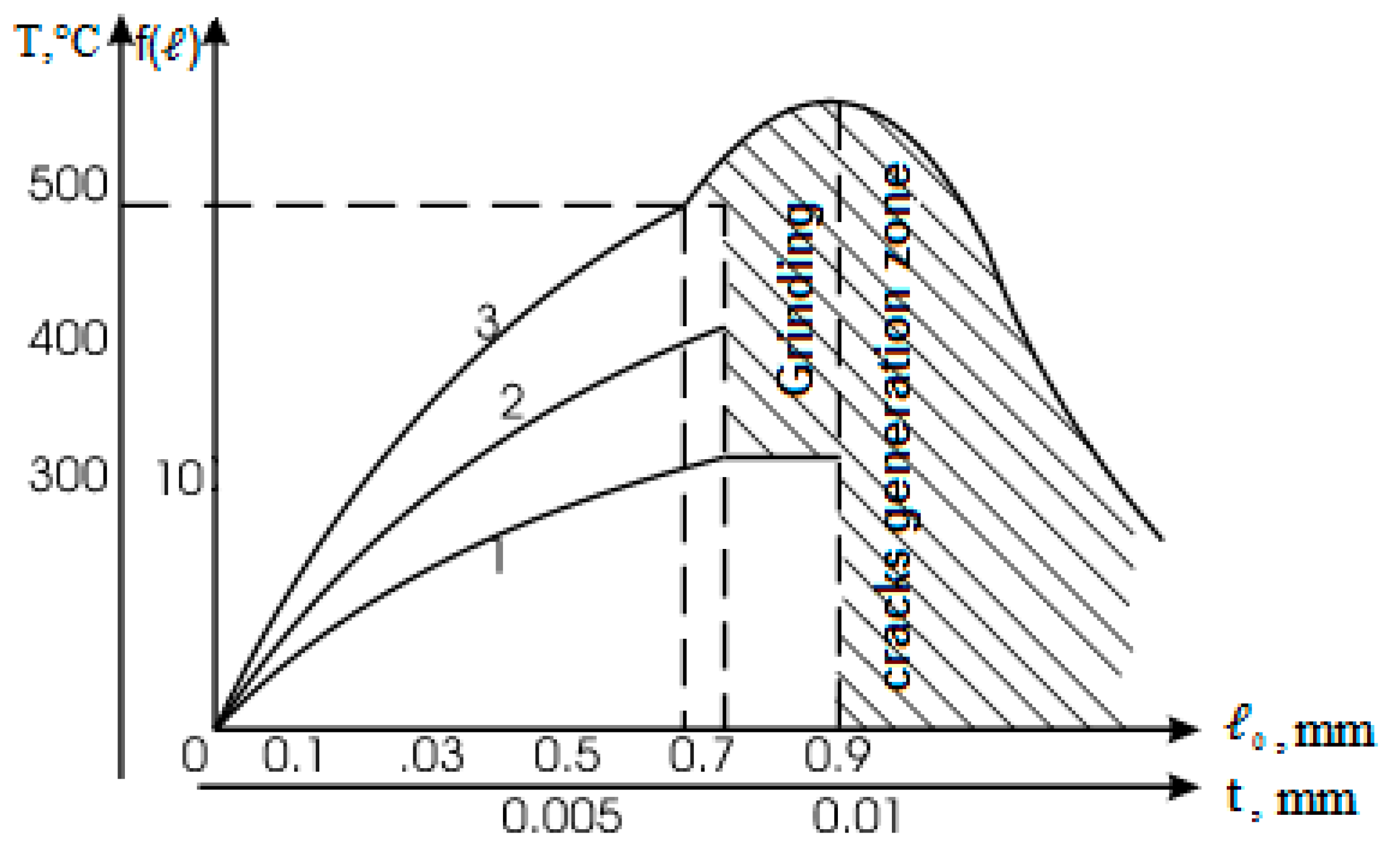
The contact temperature within the grinding area was examined to verify the zero-defect criteria (37–45). Since depth of cut is one of the dominating factors of the grinding regime that affects the thermal stress state of the processed surface, the relationship was determined (Figure 5). Other grinding regime parameters were set, taking into account the condition of maximum productivity providing the required quality. Estimated experimental results for the limit size values of the grinding cracks during the process of plasma coatings grinding for grinding parameters ; ; are presented in Figure 5.
Experimental investigations revealed that diamond abrasive wheels are characterised by stable cutting ability, high dimensional stability, and relatively low temperatures in the grinding zone, which allows processing coatings without grinding cracks for a higher depth of cut compared to the aluminium oxide grinding wheels.
It was determined that the highest productivity of the coatings grinding process providing the required surface quality is reached for the bakelite-bonded diamond wheels with a grain size of 80–100 μm (graph 1, Figure 5).
Since the porosity of a coating is regulated by the velocity of plasma jet as well as the other parameters of the spraying process, it is possible to prevent defects propagation by adjusting the grinding regime characteristics.
The results of the microhardness of the processed surface and the coating material structure studied proved that there are no structural changes in the wear-resistant TiC coating for the range of the examined grinding regimes that meet zero-defect conditions.
7. Conclusions
The developed mathematical model describes thermomechanical processes in the coating layer during its grinding, considering structural defects that have a significant impact on the formation of grinding cracks. Thus, an estimated relationship between the criterion of crack resistance and the controlling technological parameters is established for the first time. According to the defined features of structural defects, limit values of the heat flux are determined to provide the required quality of processed surfaces.
The presented method enables selecting technological conditions of processing coating materials depending on the residual stresses and defects of their structure that tend to trigger cracking during the process of grinding. This contributes to reducing the defects rate during finishing operations and increasing the exploitation qualities of the created tools.
The obtained mathematical model of the temperature thermal field and the stress–strain state of the workpiece is an important basis for the future research of the grinding process. Further investigation can be focused on the optimisation of an abrasive material removal to take into account the condition of the maximum productivity of the process and the constraints formulated in this study. Analysis of this problem is expected to be based on the genetic algorithm improved for the purpose of CAD development.
Author Contributions
Contributions: A.V.U. and V.M.T.—research and methodology, P.V.D.—methodology and analysis, and O.V.R.—formal analysis.
Funding
This research received no external funding.
Conflicts of Interest
The authors declare no conflict of interest.
References
- Malkin, S.; Guo, C. Thermal Analysis of Grinding. CIRP Ann. 2007, 56, 760–782. [Google Scholar] [CrossRef]
- Rowe, W.B.; Morgan, M.N.; Batako, A.; Jin, T. Energy and temperature analysis in grinding. Trans. Eng. Sci. 2003, 44, 3–23. [Google Scholar]
- González-Santander, J.L. Maximum Temperature in Dry Surface Grinding for High Peclet Number and Arbitrary Heat Flux Profile. Math. Probl. Eng. 2016, 9, 8470493. [Google Scholar] [CrossRef]
- Brinksmeier, E.; Aurich, J.C.; Govekar, E.; Heinzel, C.; Hoffmeister, H.W.; Klocke, F.; Peters, J.; Rentsch, R.; Stephenson, D.J.; Uhlmann, E.; et al. Advances in modelling and simulation of grinding processes. CIRP Ann. Manuf. Technol. 2006, 55, 667–696. [Google Scholar] [CrossRef]
- Deivanathan, R.; Vijayaraghavan, L. Theoretical analysis of thermal profile and heat transfer in grinding. Int. J. Mech. Mater. Eng. 2013, 8, 21–31. [Google Scholar]
- Zhou, H.; Ding, W.; Liu, C. Material removal mechanism of PTMCs in high-speed grinding when considering consecutive action of two abrasive grains. Int. J. Adv. Manuf. Technol. 2019, 100, 153–165. [Google Scholar] [CrossRef]
- Dai, C.; Ding, W.; Zhu, Y.; Xu, J.; Yu, H. Grinding temperature and power consumption in high speed grinding of Inconel 718 nickel-based superalloy with vitrified CBN wheels. Precis. Eng. 2018, 52, 192–200. [Google Scholar] [CrossRef]
- Qian, N.; Ding, W.; Zhu, Y. Comparative investigation on grindability of K4125 and Inconel718 nickel-based superalloys. Int. J. Adv. Manuf. Technol. 2018, 97, 1649–1661. [Google Scholar] [CrossRef]
- Gu, Y.; Li, H.; Du, B.; Ding, W. Towards the understanding of creep-feed deep grinding of DD6 nickel-based single-crystal superalloy. Int. J. Adv. Manuf. Technol. 2019, 100, 445–455. [Google Scholar] [CrossRef]
- Zhang, L. Chapter 4: Numerical analysis and experimental investigation of energy partition and heat transfer in grinding. In Heat Transfer Phenomena and Applications; IntechOpen Ltd.: London, UK, 2012; pp. 79–98. [Google Scholar]
- Usov, A.V.; Batyrev, A.A. Mathematical modeling of the control processes of construction elements coatings on the basis of the singular integral equations. J. Mech. Eng. 2010, 13, 65–75. [Google Scholar]
- Li, C.H.; Li, J.Y.; Wang, S.; Zhang, Q. Modeling and numerical simulation of the grinding temperature field with nanoparticle jet of MQL. Adv. Mech. Eng. 2013, 5, 986984. [Google Scholar] [CrossRef]
- Masoumi, H.; Safavi, S.M.; Salehi, M. Grinding force, specific energy and material removal mechanism in grinding of HVOF-sprayed WC–Co–Cr coating. Mater. Manuf. Processes 2014, 29, 321–330. [Google Scholar] [CrossRef]
- Youtsos, A.G. Residual Stress and Its Effects on Fatigue and Fracture; Springer: Dordrecht, Netherlands, 2006; pp. 15–26. [Google Scholar]
- Ding, W.F.; Zhang, L.C.; Li, Z.; Zhu, Y.J.; Su, H.H.; Xu, J.H. Review on grinding-induced residual stresses in metallic materials. Int. J. Adv. Manuf. Technol. 2016, 88, 2939–2968. [Google Scholar] [CrossRef]
- Sundarrajan, K.D. Study of Grinding Burn Using Design of Experiments Approach and Advanced Kaizen Methodology. Master’s Thesis, University of Nebraska, Lincoln, NE, USA, May 2012. [Google Scholar]
- Badger, J.A.; Torrance, A. Burn awareness. Understanding the causes of grinding burn helps alleviate the problem. Cut. Tool Eng. Mag. 2000, 12, 52. [Google Scholar]
- Agarwal, S.; Rao, P.V. Experimental investigation of surface/subsurface damage formation and material removal mechanisms in SiC grinding. Int. J. Mach. Tools Manuf. 2008, 48, 698–710. [Google Scholar] [CrossRef]
- Todd, R.I.; Derby, B. Thermal stress induced microcracking in alumina–20% SiCp composites. Acta Mater. 2004, 52, 1621–1629. [Google Scholar] [CrossRef]
- Masoumi, H.; Safavi, S.M.; Salehi, M.; Nahvi, M. Effect of grinding on the residual stress and adhesion strength of HVOF thermally sprayed WC–10Co–4Cr coating. Mater. Manuf. Processes 2014, 29, 1139–1151. [Google Scholar] [CrossRef]
- Vencl, A.; Arostegui, S.; Favaro, G.; Zivic, F.; Mrdak, M.; Mitrovic´, S.; Popovic, V. Evaluation of Adhesion/Cohesion Bond Strength of the Thick Plasma Spray Coatings by Scratch Testing on Coatings Cross-Sections. Tribol. Int. 2011, 44, 1281–1288. [Google Scholar] [CrossRef]
- Nikolaev, A.G.; Tanchik, E.A. New addition theorems of basic solutions of the Lame equation for prolatespheroids and their application to modeling porous material. Aerosp. Tech. Technol. 2014, 5, 47–55. [Google Scholar]
- Usov, A.V.; Vorobyova, L.A.; Smirnyi, S.G. Research of thermomechanical effects at grinding materials and alloys apt to crack rise. Eastern-Eur. J. Enterp. Technol. 2015, 2, 48–56. [Google Scholar] [CrossRef]
- Tonkonogyi, V.; Yakimov, A.; Bovnegra, L. Increase of Performance of Grinding by Plate Circles; Springer International Publishing AG: Basel, Switzerland, 2018; pp. 121–127. [Google Scholar]
- Wojcik, R.; Wlazlo, J. Damage of the Surface Layer Gears in Grinding Process. Mech. Mech. Eng. 2013, 17, 317–323. [Google Scholar]
- Grigoriev, S.N.; Volosova, M.A. Comprehensive analysis of internal and surface defects of ceramics. In Proceedings of the International Conference on Nanomaterial, Semiconductor and Composite Materials, Singapore, 21–22 May 2016. [Google Scholar]
- Costa, N.; Silva, F.S. Influence of process stages over fatigue crack behaviour of electroplated chromium coatings. In Proceedings of the 5th International Surface Engineering Congress, Washington State Convention Center, Seattle, WA, USA, 15–17 May 2006; pp. 97–101. [Google Scholar]
- Thirumalaikumarasamy, D.; Shanmugam, K.; Balasubramanian, V. Influences of atmospheric plasma spraying parameters on the porosity level of alumina coating on AZ31B magnesium alloy using response surface methodology. Prog. Nat. Sci. Mater. Int. 2012, 22, 468–479. [Google Scholar] [CrossRef] [Green Version]
- Juzkova, R.; Ctibor, P.; Benes, V. Analysis of porous structure in plasma-sprayed coating. Image Anal. Stereol. 2011, 23, 45–52. [Google Scholar] [CrossRef]
- Behera, A.; Mishra, S.C.; Behera, A.; Dhal, J.P. Porosity Analysis of Plasma Sprayed Coating by Application of Soft Computing. J. Mater. 2013, 6, 150671. [Google Scholar] [CrossRef]
- Espinal, L. Porosity and Its Measurement. In Characterization of Materials; John Wiley & Sons, Inc.: Hoboken, NJ, USA, 2012. [Google Scholar]
- Du, H.; Chen, H.; Moom, B.K.; Shin, J.H.; Lee, S.W. Effect of Plasma Spraying Condition on Deposition Efficiency, Microstructure and Microhardness of TiO2 Coating. Adv. Technol. Mater. Mater. Process. 2004, 6, 152–157. [Google Scholar]
- Tonkonogyi, V.M.; Sinkovskii, A.S.; Rybak, O.V. Analysis of characteristics of composite powders for plasma spraying based on ТіС–Ni(P)–Cu for the purpose of the coatings grinding CAD development. Cut. Tools Technol. Syst. 2018, 88, 216–223. [Google Scholar]
- Tonkonogyi, V.; Usov, A.; Dašić, P.; Rybak, O.; Bovnegra, L. Modeling of temperature field and stress-strain state of the workpiece with plasma coatings during surface grinding. J. Res. Dev. Mech. Ind. 2018, 10, 81–90. [Google Scholar]
- Sobhanverdi, R.; Akbari, A. Porosity and microstructural features of plasma sprayed Yttria stabilized Zirconia thermal barrier coatings. Ceram. Int. 2015, 41, 14517–14528. [Google Scholar] [CrossRef]
- Kulkarni, A.; Vaidya, A.; Goland, A.; Sampath, S.; Herman, H. Processing effects on porosity-property correlations in plasma sprayed yttria-stabilized zirconia coatings. Mater. Sci. Eng. 2003, 359, 100–111. [Google Scholar] [CrossRef]
- Muhammad, M.M.; Jalar, A.; Shamsudin, R.; Isa, M.C. Effect of plasma spray parameters on porosity of fly ash deposited coatings. AIP Conf. Proc. 2014, 1614, 116–121. [Google Scholar]
- Kaßner, H.; Stuke, A.; Rödig, M.; Vaßen, R.; Stöver, D. Influence of porosity on thermal conductivity and sintering in suspension plasma sprayed thermal barrier coatings. Ceram. Eng. Sci. Proc. 2009, 29, 147–158. [Google Scholar]
- Venkataraman, R.; Das, G.; Singh, S.R.; Pathak, L.C.; Ghosh, R.N.; Venkataraman, B.; Krishnamurthy, R. Study on influence of porosity, pore size, spatial and topological distribution of pores on microhardness of as plasma sprayed ceramic coatings. Mater. Sci. Eng. 2007, 445, 269–274. [Google Scholar] [CrossRef]
Figure 1.
Schematic of material removal in surface grinding.

Figure 2.
Condition monitoring algorithm for grinding plasma coatings.

Figure 3.
Modelling of the temperature field of the plasma coatings’ grinding process.

Figure 4.
Temperature spread in a workpiece over grinding time.

Figure 5.
Estimated experimental results for the limit size values of grinding cracks during the process of plasma coatings grinding using abrasive wheels with following characteristics: 1–synthetic diamond bakelite-bonded grinding wheel with 80–100 μm grain size; 2—synthetic diamond metal-bonded grinding wheel with 200–250 μm grain size; 3–white aluminium oxide vitrified-bonded grinding wheel with 250–315 μm grain size.

© 2019 by the authors. Licensee MDPI, Basel, Switzerland. This article is an open access article distributed under the terms and conditions of the Creative Commons Attribution (CC BY) license (http://creativecommons.org/licenses/by/4.0/).
Share and Cite
MDPI and ACS Style
Usov, A.V.; Tonkonogyi, V.M.; Dašić, P.V.; Rybak, O.V. Modelling of Temperature Field and Stress–Strain State of the Workpiece with Plasma Coatings during Surface Grinding. Machines 2019, 7, 20. https://doi.org/10.3390/machines7010020
AMA Style
Usov AV, Tonkonogyi VM, Dašić PV, Rybak OV. Modelling of Temperature Field and Stress–Strain State of the Workpiece with Plasma Coatings during Surface Grinding. Machines. 2019; 7(1):20. https://doi.org/10.3390/machines7010020
Chicago/Turabian StyleUsov, Anatoly V., Vladimir M. Tonkonogyi, Predrag V. Dašić, and Olga V. Rybak. 2019. "Modelling of Temperature Field and Stress–Strain State of the Workpiece with Plasma Coatings during Surface Grinding" Machines 7, no. 1: 20. https://doi.org/10.3390/machines7010020
Note that from the first issue of 2016, this journal uses article numbers instead of page numbers. See further details here.