Comparative Analysis of Machining Procedures

1
Institute of Manufacturing Science, University of Miskolc, Miskolc-Egyetemvaros, 3515 Miskolc, Hungary
2
Institute of Management Science, University of Miskolc, Miskolc-Egyetemvaros, 3515 Miskolc, Hungary
*
Author to whom correspondence should be addressed.
Machines 2018, 6(2), 13; https://doi.org/10.3390/machines6020013
Submission received: 28 February 2018
/
Revised: 21 March 2018
/
Accepted: 22 March 2018
/
Published: 28 March 2018
(This article belongs to the Special Issue Precision Machining)
Abstract
:The in-depth analysis of cutting procedure is a topic of particular interest in manufacturing efficiency because in large-scale production the effective use of production capacities and the revenue-increasing capacity of production are key conditions of competitiveness. That is why the analysis of time and material removal rate, which are in close relation to production, are important in planning a machining procedure. In the paper three procedures applied in hard cutting are compared on the basis of these parameters and a new parameter, the practical parameter of material removal rate, is introduced. It measures not only the efficiency of cutting but also that of the whole machining process because it includes the values measured by time analysis as well. In the investigations the material removal rate was analyzed, first on the basis of geometrical data of the component. After that different machining procedures (hard machining) were compared for some typical surfaces. The results can give some useful indications about machining procedure selection.
1. Introduction
Machining procedures for machining industry components have developed rapidly in the last decade thanks to new, powerful machines with high load bearing capacities, the materials used in their structures, and their ever more advanced control systems. This technological development facilitates the machining of components with higher accuracy and better surface quality in shorter time. Due to the shorter machining time, more components can be produced within a given time and therefore more profit can be earned. Exact determination of time parameters directly connected to machining is critical, considering that the time decrease of one component is significant if the sum of these time values is considered over a year. This can result in a high revenue surplus in mass production. In the time of Industry 4.0, when the conception of computer controlled automated plants is being extended, automatic data collection and analysis can be utilized to help in intelligent decision-making. This means the time data of production processes are available in a shorter time and at a higher level of accuracy [1,2,3,4]. For a given technology the machining time and cost can basically be optimized by the cutting data (cutting speed, depth-of-cut, feed, etc.). Additionally, rationalization of supporting activities of a production process can decrease the times connected directly or indirectly to the machining. This means that decreases can be made in the preparation time or the time needed for material handling among the workplaces, for instance. Several plant management solutions for this purpose have evolved in recent decades, e.g., lean production, six sigma or the theory of constraints [5,6].
Beyond changes in cutting data and the rationalization of manufacturing organization, another essential factor in increasing of production efficiency is the choice of procedures or procedure versions used in machining a given component. If the same surface quality and accuracy can be achieved by two procedures using completely different technologies, the two versions [7] can be considered as perfectly replaceable alternatives from the point of view of machining [8]. In addition to that, of course, the investment volume and other costs related to the machine and equipment needs of the procedures have to be compared, like a skilled workforce or maintenance. Three machining procedures are compared in the paper for finishing hardened surfaces. Conventional grinding is considered as the base point and hard turning and a combined procedure are compared to it. Hard turning and the combined procedure are new solutions in machining but several aspects of conventional grinding are still researched [9,10] In the latter procedure hard turning and grinding are applied in one clamping of the workpiece in order to exploit the advantages of both procedures. This begins with hard turning, whose material removal efficiency is relatively high but which forms a periodic topography, which is not always suitable for requirements for in-built components. Thus, grinding is necessary after cutting with a single-point cutting tool. In this case including grinding in the combined procedure reduces the material removal efficiency compared to hard turning by only a small extent, because to remove periodic topography it is sufficient to remove only a minimal depth of material (Rmax scale of the hard turned surface). As this is done in one clamping with hard turning, it leads to little increase in machining time, or even a decrease [11,12].
2. Method of Analysis
The investigation was carried out for gear wheel finish machining operations. These machine parts have three geometrically distinct surfaces that must be machined. Thus, with the introduced calculation method, the analysis can be applied reliably and simply not only for the different procedures but for the different typical surfaces too. Our earlier experiments dealt with the increase in material removal efficiency achievable by changing technological data, comparing also these three procedures [13,14]. In this study the machining time (Tm), the operation time (Top), the theoretical value of material removal rate (Qw) and the practical material removal rate (Qwp) were analyzed in the three machining procedures. After that the effect of changes in geometrical data (bore length and diameter) on the practical material removal rate in machining internal cylindrical surface were analyzed. In the first step the efficiency of material removal was analyzed using the theoretical material removal rate. This parameter can be determined on the basis of the cutting and geometrical data of a component, but a more accurate picture of efficiency can be gained if a time base characterized by real production circumstances is considered.
For this purpose we define a parameter that considers these times, naming it of the practical material removal rate. This practical indicator is also suitable for characterizing production processes (machining and connecting production organization). Thus, calculations by this parameter are suitable to support more complex technological decisions. The logic of this is outlined in Figure 1.
3. Material Removal Efficiency Measurement Parameters
3.1. Time Parameters
A relatively inflexible feature of machining is the machining time, i.e. the time the workpiece spends in machining on a machine tool. Reduction of this is possible as long as the quality requirements can still be fulfilled. The other useful parameter is the operation time, which includes the preparation and finishing time of machining, the supplementary times, and other times of operations and processes that are directly needed to produce a component. Projecting the times beyond machining time to one workpiece can also be significant, therefore the reduction of such times is also important for the planners of production process. In our experiments we analyzed machining of the internal cylindrical surface (ICS), plain surface (PS) and shaped surface (SS)—a cone. In the analysis hard turning performed by a single-point tool (ICS, PS, SS), face grinding (PS) and in-feed grinding (ICS, SS) were compared. Calculations were performed by the following formulas. The variables of the formulas are summarized in Table 1.
Bore grinding (roughing and smoothing passes):
In-feed bore and cone grinding (roughing and smoothing passes):
Face grinding (roughing and smoothing passes):
Hard turning of bore, cone and face (roughing and smoothing passes):
Combined procedure (hard turning and then in-feed grinding):
Several methods exist for the calculation of operation time of machining. Here we present the formulas applied in the plant where the analyzed gears are machined.
where Top is operation time, Tprep time of preparation and finish, Tpiece piece time, Tbase base time, Tsuppl supplementary time, Tm machining time, Tmanip workpiece manipulation time, and k is a coefficient whose value here is 0.2.
3.2. Material Removal Rate
The theoretical material removal rate (Qw) defines what material volume can be removed from the surface in a time unit. It does not consider the time of machining during which the workpiece is not physically cut (e.g., manipulation). That is why it only shows the effect of change of technological data. This parameter can be calculated in the different procedures. Since it does not include all factors (e.g., sparking out, tool overrun), it cannot be considered as a sufficiently exact parameter in comparing different procedures. The calculation method of the theoretical parameter is summarized in Table 2.
In the calculation of the practical parameter the removed material volume is divided by a certain time data (Tx) characterizing the production of a surface element/surface/component. This value will be the specific material volume, i.e. the parameter measures the material removal rate while considering the time components of machining. If the preferred technological decision factor is the specific material volume removed while the workpiece is clamped, the machining time is considered. If other supplementary times significantly influence the production, the piece time is considered, and so on. In our analyses operation time was included in the calculations. Since the operation time is what expresses the real time consumption, we can also draw conclusions on the efficiency of the whole production process. The practical material removal rates calculated by the operation time are given by Equations (11)–(13).
Bore:
Face:
Cone:
where L is machined bore length, d workpiece diameter, Z allowance, α half cone-angle, and Tx considered time.
The rate of theoretical to practical parameters shows the rate of extra time necessary for machining compared to the machining time. We note that the surface rate is a similar parameter. That differs from the material removal rate in showing the specific area of removed surface. The value of the parameter is equal to that of the material removal rate if material removal is performed in one pass.
4. Basic Data of Comparison Analyses
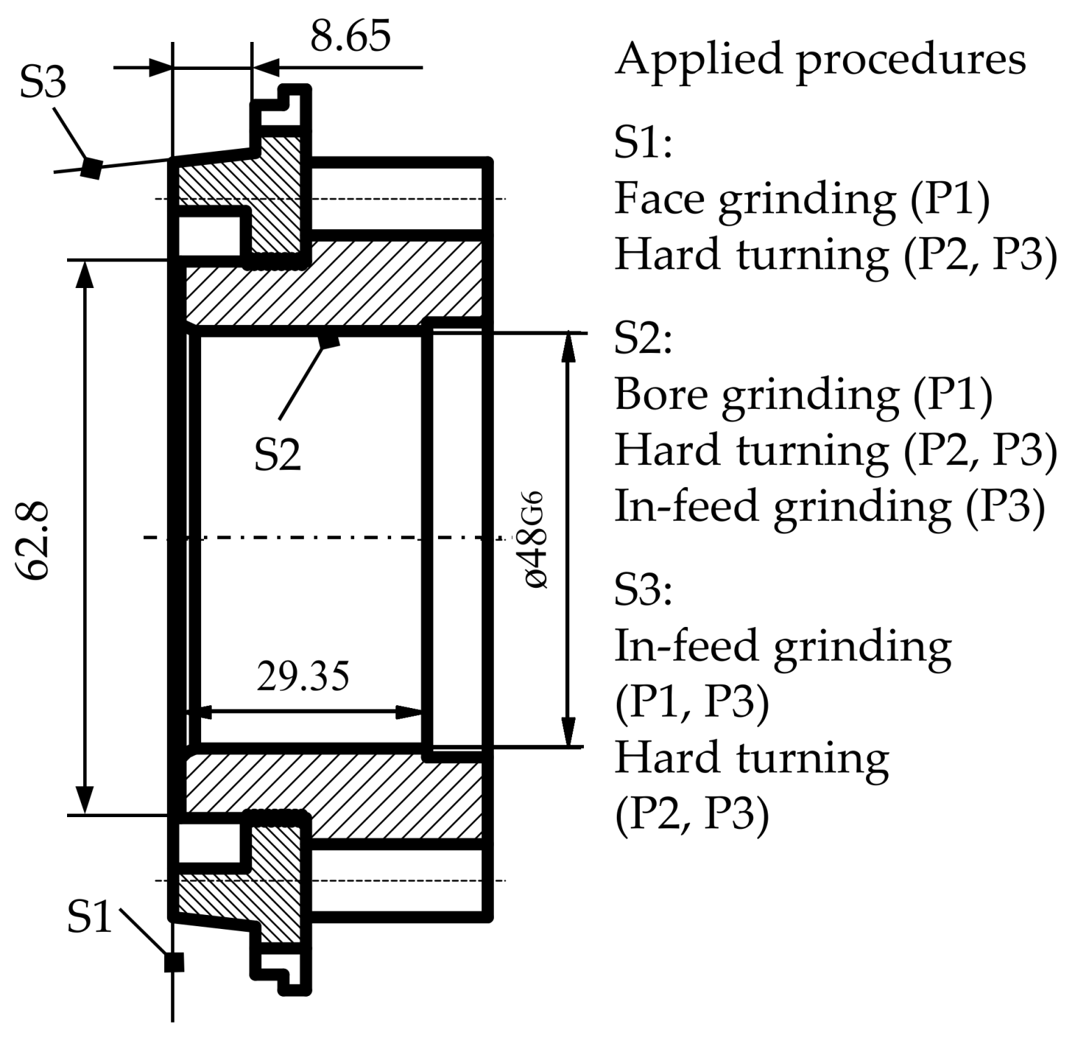
In the study calculations were made for the machining of an analyzed gear wheel. The component is comprised of one plain surface, one conical surface and one internal cylindrical surface to be machined. The material of the component was 16MnCr5 (HRC 62). Its geometrical and cutting data are summarized in Figure 2 and Table 3, where the symbols are:
- Procedures: P1: grinding; P2: hard turning; P3: combined procedure (P3/1: hard turning, P3/2: in-feed grinding)
- Surfaces: S1: face; S2: bore; S3: cone
5. Results and Discussion
5.1. Theoretical Material Removal Rate
The theoretical values of the material removal rate are summarized in Table 4. Machining of the typical surfaces of the component cannot be compared directly with the theoretical values but certain conclusions can be made. For example the bore (S2) can be machined more effectively by hard turning (P2) than by grinding (P1) because 6.75 > 3.32 and 0.72 > 0.3 in the same time. Concerning the machining of the face (S1) the two procedures cannot be compared because in grinding the material removal is carried out in two passes and in hard turning in only one pass.
5.2. Practical Parameter of Material Removal
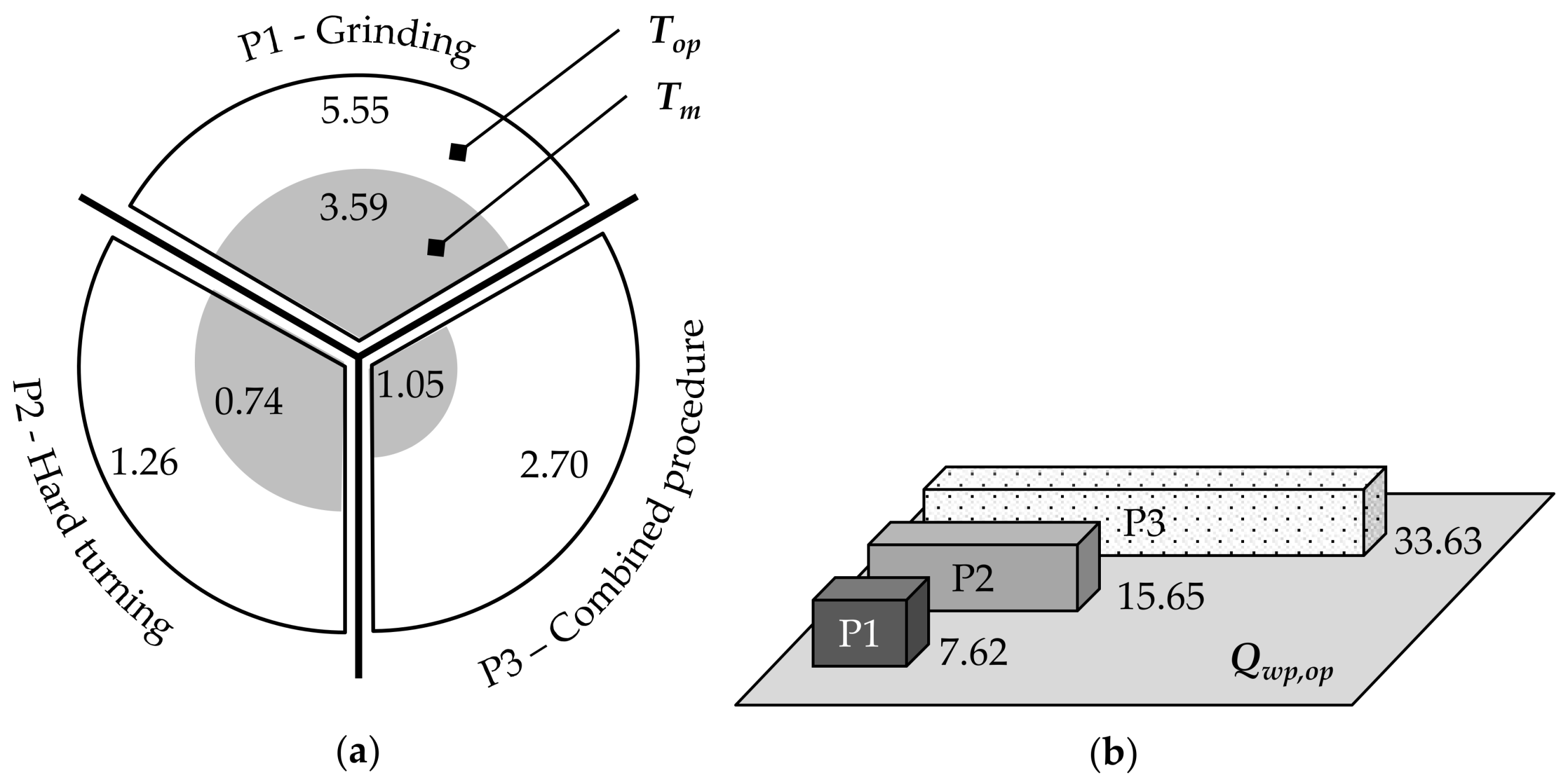
In Table 5 the machining time, the operation time and the practical values of material removal rate (Qwp,op) are summarized for a given component. The rate of machining time to operation time was analyzed and is illustrated in Figure 3a. Operation time is considered as 100 percent. While in grinding the operation time is 1.56 times higher than the machining time, this value is 1.7 in hard turning and 2.57 in the combined procedure. The arcs representing the procedures also give the absolute time values. This figure highlights that there is a relatively large difference between the machining and the operation times and that is why it is worth focusing on the role of operation time in efficiency analyses. The values of the practical material removal parameter are given in Figure 3b. The values of grinding and the combined procedure are lower than those of hard turning for the analyzed component. In the figure it can be seen that despite this great difference the Qwp,op value of the combined procedure exceeds that of grinding. It is noted that in selection of the procedures not only the machining efficiency but also the costs of the procedures have to be calculated (e.g., machine tool investment).
5.3. Effect of Bore Length and Diameter
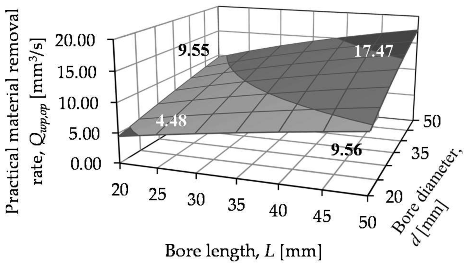
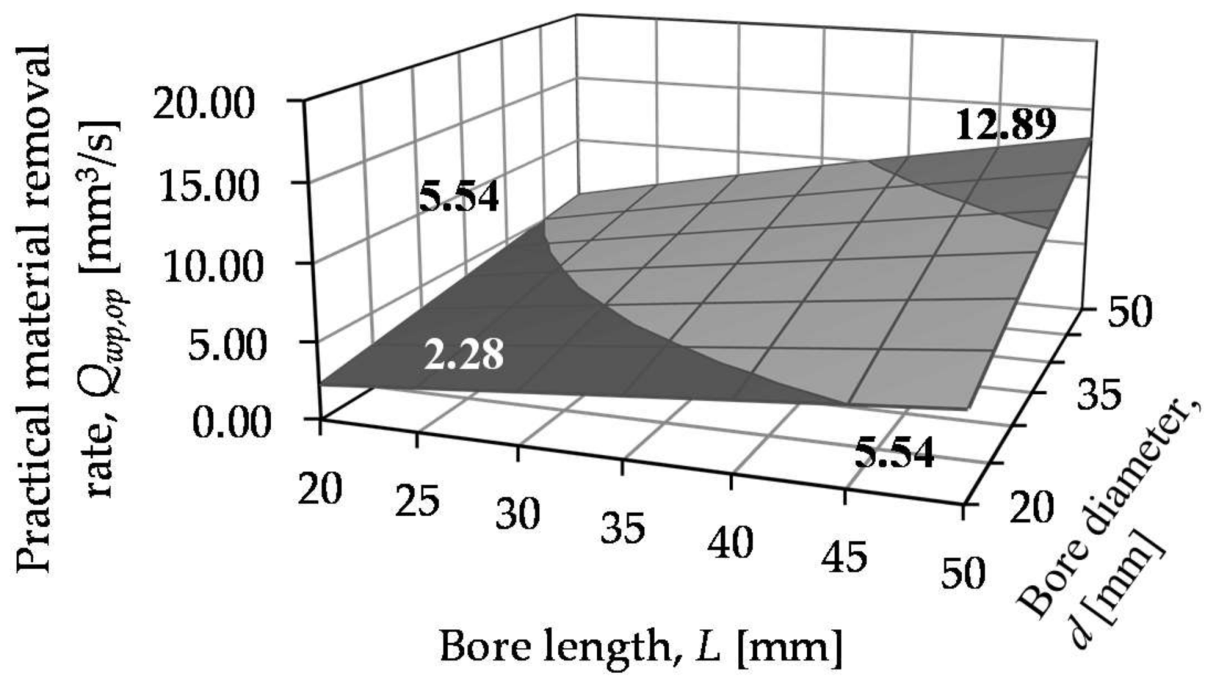
The practical material removal rates of the three procedures are summarized in Figure 4, Figure 5 and Figure 6.
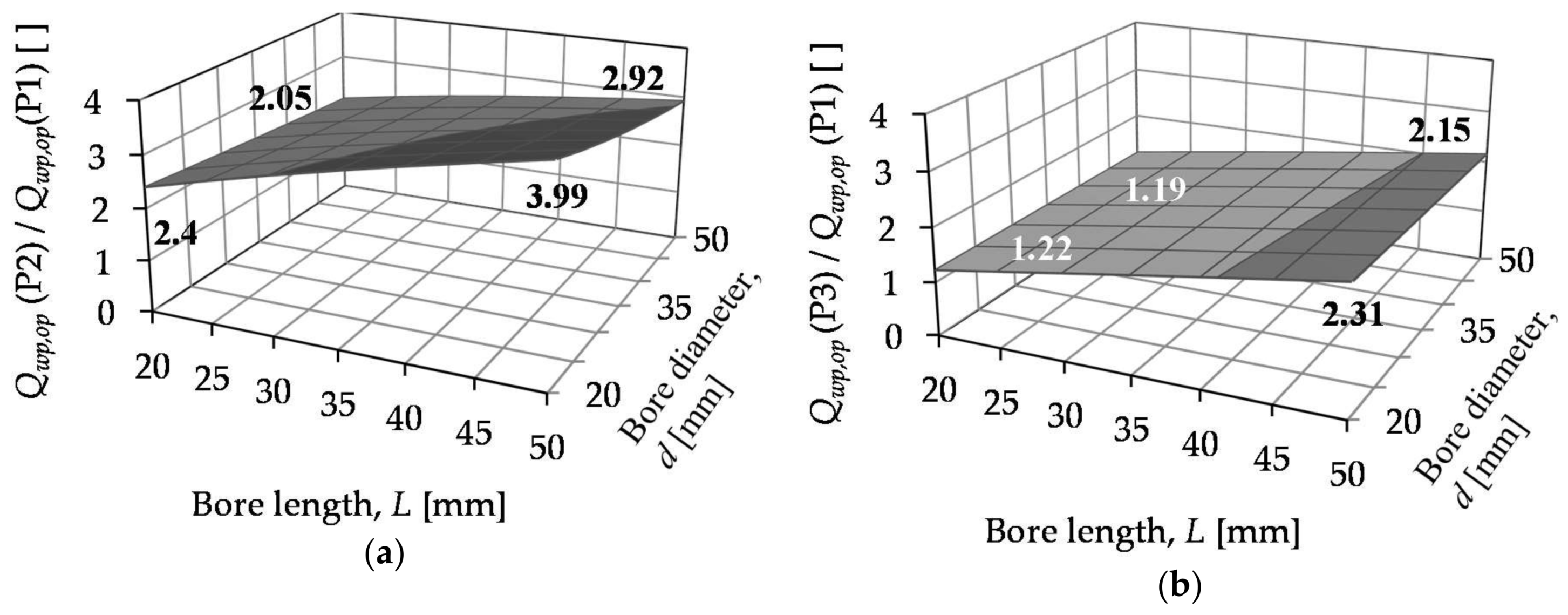
In Figure 7 the practical parameters of hard turning and the combined procedure are compared to those of grinding for different bore diameters and bore lengths when machining internal cylindrical surfaces, since this type of surfaces is hard to machine.
In both procedures the difference is clear, namely the value of the practical material removal rate for hard turning exceeds that of the combined procedure but the value of the combined procedure is considerably better than that of grinding. Although the practical material removal rate is the highest in hard turning, the operation circumstances of the component can require the application of the combined procedure. In Figure 5 and Figure 6 it can be seen that with the increase of both the diameter and the bore length the practical value of material removal rates increases. In hard turning when the bore length and the diameter are between 20 and 50 mm, the Qwp,op values are between 4.48 and 17.47 mm3/s. In the combined procedure these values are between 2.33 and 13.12 mm3/s. In Figure 7 the rates of Qwp,op compared to that of grinding (P1) are given for the introduced procedures (P2, P3). In hard turning the values of practical material removal rate are 2.05–3.99 times higher than those of the grinding. In the combined procedure these values are between 1.25 and 2.36. Application of the practical material removal rate analysis for geometrical data can supports the construction design of components.
6. Conclusions
Through analyzing the material removal rate the efficiency of machining procedures was calculated. This parameter characterizes the efficiency of the different machining procedures well but it does not facilitate the comparison of different procedures or procedure versions. To compare the procedures the practical parameter was analyzed. The Qwp,op value of grinding is 23 percent that of hard turning for the analyzed gear wheels. The practical material removal rate of the combined procedure is 47 percent that of hard turning. That is why the combined procedure is expedient to substitute for grinding if it is necessary to form a random topography. The practical value of the material removal rate Qwp,op is suitable for technological decision support within certain limits. It allows more analysis possibilities than the theoretical value because it provides more information than simple time data. However, it does not consider the direct and indirect costs related to machining, which can modify the decision made for the procedure choice. In the analysis of bore length and diameter, the increase of these two variables results in an increase in the practical material removal rate in case of fixed cutting data. In our tests both geometrical data were varied between 20 and 50 mm. In increasing both the bore length and bore diameter the Qwp,op increases 1.83–2.13-fold in hard turning. For smaller diameters and bore lengths the extent of increase is higher if only one parameter is changed at one time. In the combined procedure the Qwp,op value increases 2.32-2.42-fold when the diameter or the length are increased. This analysis can be useful in construction design of machined components. In summary, the method introduced here can be applied in the comparison of three separate aspects: different machining procedures; machining of components that contain different types of surfaces and identical types of surfaces with different geometrical values. These comparisons provide information not only about the efficiency of the applied procedures but also about the organization efficiency of production.
Acknowledgments
Project no. NKFI-125117 has been implemented with the support provided from the National Research, Development and Innovation Fund of Hungary, financed under the K_17 funding scheme.
Author Contributions
Janos Kundrak and Viktor Molnar conceived and designed the experiments; Viktor Molnar and Istvan Deszpoth performed the experiments; Istvan Deszpoth and Janos Kundrak analyzed the data; Janos Kundrak and Viktor Molnar wrote the paper.
Conflicts of Interest
The authors declare no conflict of interest.
References
- Hammer, M.; Somers, K.; Karre, H.; Ramsauer, C. Profit per hour as a target process control parameter for manufacturing systems enabled by Big Data analytics and Industry 4.0 infrastructure. Procedia CIRP 2017, 63, 715–720. [Google Scholar] [CrossRef]
- Tamas, P.; Illes, B.; Dobos, P. Waste reduction possibilities for manufacturing systems in the industry 4.0. IOP Conference Series. Mater. Sci. Eng. 2016, 161, 1–8. [Google Scholar] [CrossRef]
- Zhong, R.Y.; Xu, X.; Klotz, E.; Newman, S.T. Intelligent Manufacturing in the Context of Industry 4.0: A Review. Engineering 2017, 3, 616–630. [Google Scholar] [CrossRef]
- König, W.; Berktold, A.; Koch, K.F. Turning versus grinding—A comparison of surface integrity aspects and attainable accuracies. Ann. CIRP 1993, 42, 39–43. [Google Scholar] [CrossRef]
- Jacobs, B.W.; Swink, M.; Linderman, K. Performance effects of early and late Six Sigma adoptions. J. Oper. Manag. 2015, 36, 244–257. [Google Scholar] [CrossRef]
- Castro, S.; Riedel, C. Assessment of the implementation of manufacturing excellence in a fiber based packaging manufacturing environment. Procedia CIRP 2017, 63, 113–118. [Google Scholar] [CrossRef]
- Kundrak, J.; Mamalis, A.G.; Markopoulos, A. Finishing of hardened boreholes: Grinding or hard cutting? Mater. Manuf. Process. 2004, 19, 979–993. [Google Scholar] [CrossRef]
- Klocke, F.; Brinkmeier, E.; Weinert, K. Capability profile of hard cutting and grinding process. Ann. CIRP 2005, 54, 22–54. [Google Scholar] [CrossRef]
- Markopoulos, A.P.; Kundrak, J. FEM/AI models for the simulation of precision grinding. Manuf. Technol. 2016, 16, 384–390. [Google Scholar]
- Dudas, L. Design of Nonconventional Grinding Wheels with Specialized CAD System. In Proceedings of the 4th IEEE International Symposium on Logistics and Industrial Informatics (LINDI 2012), Smolenice, Slovakia, 5–7 September 2012; pp. 21–26. [Google Scholar]
- Tönshoff, H.K.; Arendt, C.; Ben Amor, R. Cutting of Hardened Steel. Ann. CIRP 2000, 49, 547–566. [Google Scholar] [CrossRef]
- Waikar, R.A.; Guo, Y.B. A comprehensive characterization of 3D surface topography induced by hard turning versus grinding. J. Mater. Process. Technol. 2008, 197, 189–199. [Google Scholar] [CrossRef]
- Kundrak, J. Alternative machining procedures of hardened steels. Manuf. Technol. 2011, 11, 32–39. [Google Scholar]
- Kundrak, J.; Varga, G.; Deszpoth, I.; Molnar, V. Some aspects of machining of bore holes. Appl. Mech. Mater. 2013, 309, 126–132. [Google Scholar] [CrossRef]
Figure 1.
Logic of the analysis.
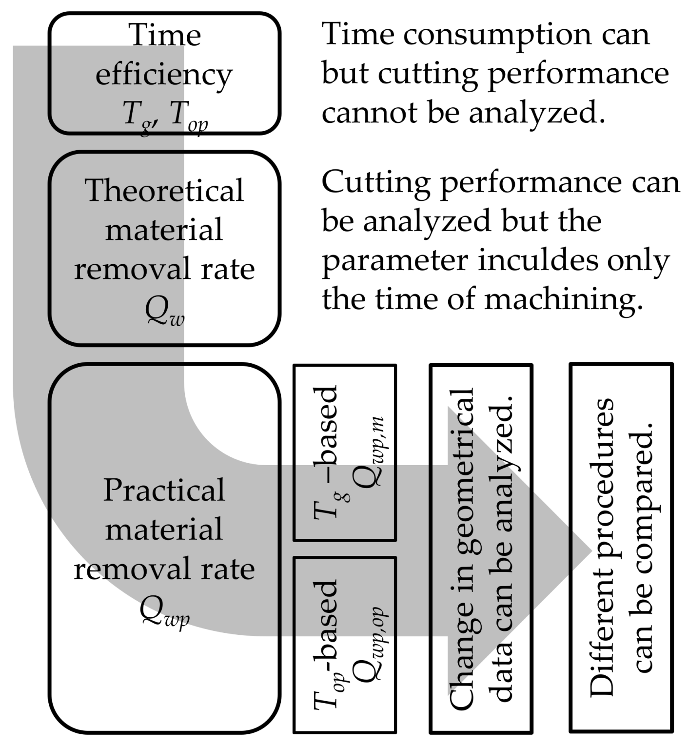
Figure 2.
Geometrical and cutting data.

Figure 3.
(a) rate of machining times within operation time (Top = 100%); (b) practical material removal rates of the three procedures.
Figure 3.
(a) rate of machining times within operation time (Top = 100%); (b) practical material removal rates of the three procedures.

Figure 4.
Qwp,op values of grinding.
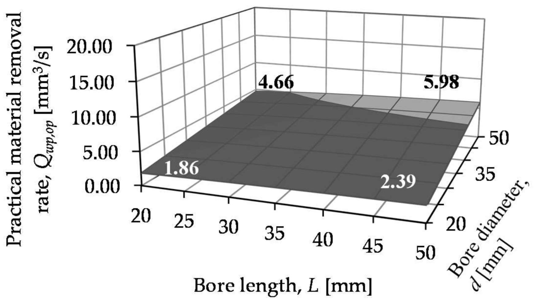
Figure 5.
Qwp,op values of hard turning.

Figure 6.
Qwp,op values of the combined procedure.

Figure 7.
Rates of material removal rates of hard turning (a) and the combined procedure (b) compared to grinding.
Figure 7.
Rates of material removal rates of hard turning (a) and the combined procedure (b) compared to grinding.


Table 1.
Geometrical and cutting data applied in the formulas of machining time.
| Symbol | Description |
|---|---|
| L | bore length |
| L′ | bore length + tool overrun |
| ZR; ZS; ZA | roughing, smoothing and air grinding allowance |
| vfL,R; vfL,S | traverse feed rate (roughing, smoothing) |
| ae,R; ae;S | depth-of-cut in grinding (roughing, smoothing) |
| iso | number of sparking out revolutions |
| vfR,R; vfR,S; vfR,A | radial feed rate in in-feed grinding (roughing, smoothing, air grinding) |
| nw | revolution per minute of the workpiece |
| ap,R; ap,S | depth-of-cut (roughing, smoothing) |
| fR, fS | roughing and smoothing feed |
| dw | workpiece diameter |
| vc | cutting speed in turning |
| tso | time of sparking out |
Table 2.
Calculation of the theoretical parameter of the material removal rate in different procedures.
Table 2.
Calculation of the theoretical parameter of the material removal rate in different procedures.
| Procedure | Qw [mm3/s] |
|---|---|
| Face grinding | apbvw |
| Bore grinding | aefvw |
| In-feed bore grinding | apdwπvfR |
| In-feed cone grinding | |
| Face turning | apfvc |
| Boring | |
| Cone turning |
Table 3.
Cutting data.
| Surface 1 (S1)—Face | P1 | Surface 2 (S2)—Bore | P1 | Surface 3 (S3)—Cone | P1 | ||
| ae,R: 0.03 mm | nk,R: 40 ds/min | ae,R: 0.01 mm/ds | vc: 32 m/s | tso: 6 s | |||
| ae,S: 0.01 mm | nk,S: 36 ds/min | ae,S: 0.001 mm/ds | vw: 98 m/min | ZN: 0.04 mm | |||
| vw: 15 m/min | fR: 24.44 mm/r | vfL,R: 2200 mm/min | vfR,R: 0.009 mm/s | ZS: 0.01 mm | |||
| vc: 30 m/s | fS: 22.22 mm/r | vfL,S: 2000 mm/min | vfR,S: 0.003 mm/s | ||||
| iso: 8 | vw: 13.6 m/min | iso: 16 | P2 | P3/1 | |||
| P2 | vc: 29 m/s | ap: 0.3 mm | ap: 0.3 mm | ||||
| ap: 0.3 mm | P2 | P3/1 | f: 0.12 mm/r | f: 0.12 mm/r | |||
| f: 0.08 mm/rev | ap,R: 0.25 mm | ap: 0.25 mm | vc: 224 m/min | vc: 224 m/min | |||
| vc: 228 m/min | ap,S: 0.05 mm | f: 0.15 mm/r | P3/2 | ||||
| P3 | fR: 0.15 mm/r | vc: 180 m/min | vc: 32 m/s | ZN: 0.035 mm | |||
| ap: 0.3 mm | fS: 0.08 mm/r | vw: 98 m/min | ZS: 0.015 mm | ||||
| f: 0.08 mm/r | vc: 180 m/min | vfR,R: 0.008 mm/s | ZA: 0.27 mm | ||||
| vc: 228 m/min | P3/2 | vfR,S: 0.003 mm/s | tso: 6 s | ||||
| vc: 40 m/s | ZN: 0.04 mm | vfR,A: 0.1 mm/s | |||||
| vw: 86 m/min | ZS: 0.01 mm | ||||||
| vfR,R: 0.005 mm/s | ZA: 0.27 mm | ||||||
| vfR,S: 0.0033 mm/s | tso: 5 s | ||||||
| vfR,A: 0.1 mm/s | |||||||
Table 4.
Values of the theoretical material removal rate (Qw).
| P1 | ||||||||
| S1 | R | 6.66 | S2 | R | 3.32 | S3 | R | 6.69 |
| S | 2.22 | S | 0.3 | S | 2.23 | |||
| P2 | ||||||||
| S1 | 5.47 | S2 | R | 6.75 | S3 | 8.06 | ||
| S | 0.72 | |||||||
| P3/1 | ||||||||
| S1 | 5.47 | S2 | 6.75 | S3 | 8.06 | |||
| P3/2 | ||||||||
| - | S2 | R | 20.62 | S3 | R | 10.44 | ||
| S | 13.61 | S | 3.91 | |||||
Table 5.
Machining time, operation time and Qwp,op.
| P1 | P2 | P3 | |
| Tm | 3.59 | 0.74 | 1.05 |
| Top | 5.55 | 1.26 | 2.70 |
| Qwp,op | 7.62 | 33.63 | 15.65 |
© 2018 by the authors. Licensee MDPI, Basel, Switzerland. This article is an open access article distributed under the terms and conditions of the Creative Commons Attribution (CC BY) license (http://creativecommons.org/licenses/by/4.0/).
Share and Cite
MDPI and ACS Style
Kundrak, J.; Molnar, V.; Deszpoth, I. Comparative Analysis of Machining Procedures. Machines 2018, 6, 13. https://doi.org/10.3390/machines6020013
AMA Style
Kundrak J, Molnar V, Deszpoth I. Comparative Analysis of Machining Procedures. Machines. 2018; 6(2):13. https://doi.org/10.3390/machines6020013
Chicago/Turabian StyleKundrak, Janos, Viktor Molnar, and Istvan Deszpoth. 2018. "Comparative Analysis of Machining Procedures" Machines 6, no. 2: 13. https://doi.org/10.3390/machines6020013
Note that from the first issue of 2016, this journal uses article numbers instead of page numbers. See further details here.