Article

Fractional Slot Concentrated Windings: A New Method to Manage the Mutual Inductance between Phases in Three-Phase Electrical Machines and Multi-Star Electrical Machines

1
Rectorat de Lille, Clg DESCARTES, 2 rue Lavoisier, Mons-En-Baroeul 59370, France
2
AREVA NP, 27 rue de l'Industrie BP 20189, Jeumont Cedex 59573, France
*
Author to whom correspondence should be addressed.
Machines 2015, 3(2), 123-137; https://doi.org/10.3390/machines3020123
Submission received: 8 April 2015 / Revised: 22 May 2015 / Accepted: 24 May 2015 / Published: 10 June 2015
(This article belongs to the Special Issue Advances in Machinery for Renewable Power Generation)

Abstract

:
Mutual inductance is a phenomenon caused by the circulation of the magnetic flux in the core of an electrical machine. It is the result of the effect of the current flowing in one phase on the other phases. In conventional three-phase machines, such an effect has no influence on the electrical behaviour of the device. Although these machines are powered by power inverters, no problem should occur. The result is not the same for multi-star machines. If these machines are using a conventional winding structure, namely distributed windings, and are powered by voltage source converters, current ripples appear in the power supply lines. These current ripples are related to magnetic couplings between the stars. Designers should check these current ripples in order to stay within the limits imposed by the specifications. These electric current disturbances also provide torque ripples. With concentrated windings, a new degree of freedom appears; the configuration—number of slots/number of poles—can have a positive impact. The circulation of the magnetic flux is the initial phenomenon that produces the mutual inductance. The main goal of this discussion is to describe a design method that is able to produce not only a machine with low mutual inductance between phases, but also a multi-star machine where the stars and the phases are magnetically decoupled or less coupled. This discussion only takes into account the machines that use permanent magnets mounted on the rotor surface. This article is part of a study aimed at designing a high efficiency generator using fractional-slot concentrated-windings (FSCW).

Graphical Abstract

1. Introduction

When high-power electric machines controlled by voltage source inverters (VSI) are designed, the best method to remain within an economically viable solution is in using the multi-star structure [1]. If we split the electrical power into numerous equal parts, each part can remain in accordance with the capacities of the power inverters. A multi-megawatt machine, which cannot be controlled by a single power inverter, can be transformed into a multi-star machine and each star can be controlled by a less powerful power inverter. In doing so, the windings can remain classic; the copper bars can be used without the need for Roebel bar technology. For many years, machines that use fractional-slot concentrated windings (FSCW) have been under study. The design of these machines is a challenge for engineers [2]. In this discussion, we explain, in the first part, the drawbacks of multi-star windings when they are associated with VSI. Some machine configurations which are using FSCW do not exhibit a high magnetic coupling between phases. These configurations are therefore able to offer multi-star configurations without high mutual inductances between the stars. In our design, we prefer the double layer configuration for the winding structure. Unfortunately, this configuration does not present a weak magnetic coupling between the stars. In the second section, we explain our choice; the objective is related to loss mitigation. In the third section, we investigate the magnetic flux flow in the stator of a machine that uses double-layer windings. Our investigation led to a design rule. This rule is very simple to use and, in a short time, provides information on mitigation of magnetic coupling between stars. The rule, the method of use and examples are presented in the last sections of the article.

2. Distributed Windings and Mutual Inductance

In the past, multi-star machines were controlled by current source inverters (CSI), and the mutual inductance between the stars was not dangerous for the life of the machines or the life of the inverters [3,4]. Nevertheless, a drawback was reported: some high-torque fluctuations are visible at low speeds. When VSIs appeared and were used as a regular method to control these electrical machines, many current ripples were observed. Simulations and experimentations were done to discover the phenomenon which induces this effect [4]. These current ripples appear when double-star machines are controlled by two unsynchronised VSIs. Hence, the pulse width modulation(PWM) used in VSI fits well with the behaviour of a single-star machine, but is not in good agreement with the behaviour of a double-star machine. A double-star machine can be assumed to be two single-star machines sharing the same stator. These two machines are linked by a magnetic coupling which is modelled by a mutual inductance. A double-star machine which is fed by two three-phase sources (sinusoidal shape) shifted by 30° electrical has no current ripple in the power lines [4]. It can be concluded that current ripples are also linked to the shape of the supplied voltage. Two methods are used to explain such an effect. The first one only takes into account the physical aspect of the magnetic coupling (Figure 1). The second method uses the model of the double-star induction machine (Figure 2). With this model, a discussion is presented in order to explain how the drawback of this magnetic coupling can be mitigated. Figure 1 shows the effect of opening or closing one power switch in the first star, which is not synchronized with the behaviour of the other switch in the second star. This change of state induces a peak of current in the power line of the second star.
Figure 1. Physical effect of the mutual inductance between stars when a commutation occurs on one star. A double-star machine can be represented as two three-phase machines linked by a magnetic coupling.
Machines 03 00123 g001
Figure 2. Model of double-star induction machine in stator d-q reference frame.
Machines 03 00123 g002
Figure 2 shows the d-q model of a double-star machine. The magnetic coupling between the two stars is represented by the inductance (Ms-Msr). When current i1, which belongs to the first star, flows in the machine, it passes through the mutual inductance Ms-Msr and the inductance Ls-Ms. Ms is the stator mutual inductance and Msr is the cyclic mutual inductance between the stator and the rotor windings. Ls-Ms is usually a low value. The behaviour of the current I1 will have a visible effect on the second star. For example, if the second star is open, the voltage measured on the second star will not be equal to zero and will follow the amount of the mutual inductance. The best case, which is also the desired case, is a mutual inductance equal to 0. It means no magnetic coupling between the stars. With a high amount of Ms-Msr in front of Ls-Ms, a change of state of one power switch in the first star produces high electrical effects on the second star: current ripples (Figure 3). The current ripples, shown in Figure 3, also have other disadvantages. Torque ripples are also observed and are related to the current ripple [4]. Usually, inductors are inserted into the power line to decrease the effect of the mutual inductance between the stars. In particular, they decrease the torque ripples. The effect of the inductors is similar to an increase of Ls-Ms. Such a magnetic coupling has no critical influence when the two stars are fed by two identical voltages where the commutations in power devices also are synchronous. The critical effect only appears when voltage sources are shifted (Figure 3) [4].
Figure 3. The current in one phase, when a double-star machine is fed by two VSI which are shifted by 30° (electrical) (Figure reproduced with the permission of N. Moubayed [4]).
Machines 03 00123 g003
As a conclusion, such a phenomenon can occur when the two voltages are not identical. These current or torque ripples appear if these two VSIs are unable to be synchronous, not only with the main frequency but also with the switching of the power devices. The modelling and the control of double-star machines and the effect of the mutual inductance remains an issue for researchers [5]. Even if N. Moubayed has suggested solutions to suppress this magnetic coupling between stars, those solutions have drawbacks and they will be discussed in the Section 4.

3. Fractional-Slot Concentrated Windings

Fractional-slot concentrated windings are not as popular as distributed windings. Their structure involves a lot of magnetic field harmonics in the airgap, which is not the best situation regarding the iron loss mitigation or the production of torque (Figure 4). Nevertheless, they are able to provide machines with short axial length which are interesting when reduced space is available. It is the reason why these machines are used in the propulsion of electric vehicles (EV) [6]. Based on the number of slots per pole and phase, named q, the windings can be classified. When this number is below 1, the winding structure is a FSCW. When it is greater than 1, the winding structure is a conventional distributed winding. As a high level of magnetic field harmonics is present in the airgap, designers prefer using the FSCW in synchronous machines with a suitable choice for the number of slots and for the number of poles [7]. The magnetic field harmonics can be reduced by numerous methods. The first one is the use of double-layer windings which destroys many harmonics and reduces others. If this is not enough, the second solution is in using q = 0.5 which destroys all the sub-harmonics. Other solutions are based on the unequal teeth widths [8]. The sub-harmonics are harmful for the permanent magnets machines, especially surface-mounted permanent magnets, when the magnets are not fractioned. Cutting the magnets into pieces can reduce the eddy current losses. Some authors have calculated the amount of mutual inductance between the phases but they have not recorded the electric currents in power lines and cannot link current ripple to mutual inductance [9]. Moreover, they worked only with one-star machines and cannot report the problem. It is true that the mitigation of magnetic coupling can be achieved with the use of single-layer windings. Unfortunately, this configuration is the worst situation for our study. Aymen M. El-Refaie wrote a brief review on FSCW in 2010 [2].Compared to double-layer windings, single-layer windings have many disadvantages. Single-layer windings have the greatest level of magnetic field harmonics in the airgap and have much more iron loss. The end turns are the longest, which increases Joule losses. The back-EMF produced by single-layer windings is less sinusoidal. It is true that single-layer windings have advantages, like better flux weakening capability, better winding factor and less manufacturing cost. Such drawbacks have a major impact on the efficiency that the advantages cannot always compensate for. Moreover, an advantage such as flux weakening is not required in all specifications. Thereafter, high-efficiency machines using FSCW will be designed with double-layer windings. Studies must be done about double-layer windings in order to find a method which is able to mitigate undesirable magnetic coupling. Such mitigation will allow the use of multi-star machines with VSIs without any operating constraints.
Figure 4. Spectrum of the flux harmonics in the air-gap for a machine using distributed windings (a) and a machine using concentrated windings (b).
Machines 03 00123 g004

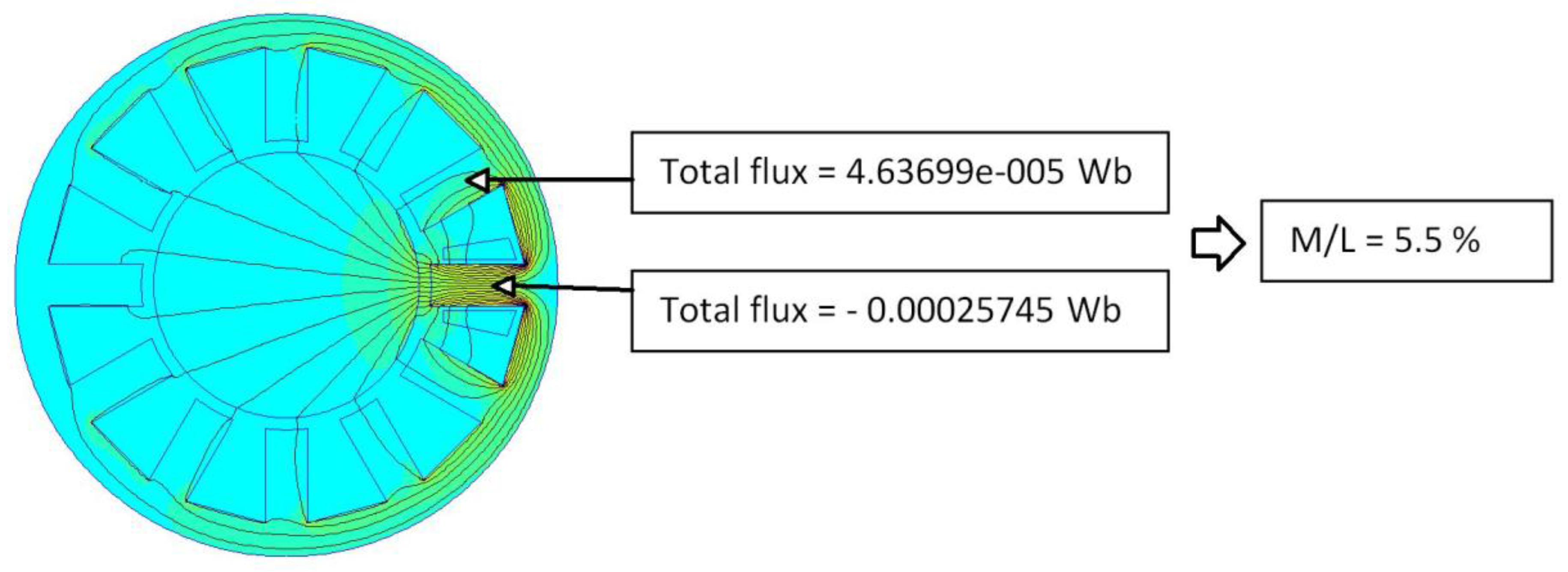
4. Flux Circulation in Concentrated Windings

The objective is well-established: less magnetic coupling between stars. Numerical simulations are able to describe the magnetic flux circulation in devices using magnetic fields [10]. It will be shown, with two examples, that concentrated windings are able to mitigate the mutual inductance between phases. The stator of a FSCW is presented in Figure 5. This structure is similar to one motor studied by Barcaro in 2010 [11]. M. Barcaro has investigated topologies with dual three-phase windings. He wants to increase the fault tolerance of a motor drive. The studied machines have two three-phase windings and 12 slots. The rotors have both interior PM (IPM) and surface-mounted PM (SPM). The two three-phase supplies are in phase except for one machine. This last machine, named DL-3, can be supplied by two three-phase inverters shifted by 30° electrical (six-phase machine). This topology is interesting as it is a true double-star machine, which is in the scope of the article. Barcaro’s main goal was not mutual inductance mitigation. He investigated the fault tolerance capability of each configuration. Doing this, he noticed that the six-phase machine has a great mutual inductance between stars and presents a “surprisingly high torque ripple”. Moreover, he also investigates the solution proposed by N. Moubayed and confirms the absent of magnetic coupling between the two stars. Unfortunately, splitting the stator into two areas, the first one for the first star and the second one for the second star, creates a high unbalanced magnetic pull in faulty operation, for example, when one star is disconnected. The six-phase machine (DL-3) should be perfect if the torque ripple can be suppressed. Now, let us examined its stator (Figure 5); the slots were not fully open. The slot depression was smaller than the airgap and could be used as a path for the flux circulation, as shown in Figure 5b, where only one coil is powered. The magnetic flux uses the slot depression and the adjacent teeth as a magnetic field path. This means that the coils associated to these adjacent teeth will be subject to a mutual effect. This phenomenon has to be suppressed. The stators with half-closed slots have to be carefully designed when the air-gap is large in front of the slot depression.
Figure 5. A stator with half-closed slots (a) is studied by simulations in order to investigate the mutual effect between one phase and the adjacent coils (b).
Machines 03 00123 g005
In the study, Barcaro calculated that the maximum ratio between the mutual and the self-inductance (M/L) for the DL-3 configuration is 34.4%. This result is in accordance with the simulation presented in Figure 5b. In Figure 6, the total magnetic flux in the main tooth and the total flux in one adjacent tooth are calculated. The comparison of these two values shows that a similar ratio is observed.
Figure 6. Only one coil is powered and the flux intensity is calculated in the main tooth and into one adjacent tooth.
Machines 03 00123 g006
It seems that the closed or semi-closed slots are not judicious structures when a low mutual inductance is needed. This idea is also confirmed by a second study [12]. Its purpose was to design a machine which uses the FSCW. This machine has to be integrated as an in-wheel direct drive in EV. It is an axial flux machine. In such machines, the slots are open. In Figure 7, the stator of an axial flux machine is presented with the coils. This structure can be compared to a stator with open slots. When the author calculated the mutual inductance between phases, he found a low value. The measured mutual inductance was less than 10% of the measured self-inductance.
Figure 7. A stator view of an axial flux electrical machine. The formed coils are placed around the teeth and the slots are opened.
Machines 03 00123 g007
Hence, simulations were done with the FSCW structure using open slots. The motor studied by Barcaro is taken as an initial example. In Figure 8, the flux distribution associated to this new structure is presented. It can be concluded that in using FSCW structure, without half-closed or closed slots, a low mutual inductance effect is found. Moreover, if the magnetic flux is decreasing in the main tooth, 0.49 mWb in the first case (Figure 6) and 0.25 mWb in the second case (Figure 8), it must be noted that the total flux goes to the rotor and does not pass elsewhere. The flux increase in the first case is a flux leakage and does not produce torque.
Figure 8. A stator with 12 open slots is studied using numerical simulations in order to investigate the mutual effect between one phase and the adjacent coils.
Machines 03 00123 g008

5. How to Manage Magnetic Fluxes in Fractional-Slot Concentrated Windings

The previous chapter has introduced a concept. Now it has to be applied and enhanced. It will also be shown that some configurations can destroy the advantage offered by the FSCW structure. When the number of phases is not imposed, it is certain that solutions using the FSCW are more numerous, and some articles have reported these solutions. Unfortunately, the effect of mutual inductance has not always been studied at the same time [13].

5.1. The Mutual Inductance can be Managed by Associations of Coils

As it is presented in Figure 8, the magnetic flux does not pass into the adjacent teeth, it is not the main magnetic path. It passes through the airgap, the rotor and uses all the other teeth as magnetic paths. With an additional coil, the remaining magnetic flux that exists in the adjacent teeth can be reduced without any impact on the main flux. Such a result can be achieved if the magnetic flux induced by this new coil generates an opposite flux in the adjacent teeth. In Figure 9, a new coil is added and its flux produces a decrease in the total magnetic flux which is present in the adjacent teeth. This positive effect is immediately demonstrated by using the magnetic flux simulations (Figure 10).
Figure 9. In this stator, with 18 open slots, a second coil is inserted. The currents in the first and in the second coil are imposed in order to keep the direction of the magnetic flux. For both coils, the magnetic flux is travelling from the right to the left.
Machines 03 00123 g009
Using Figure 10, it can be concluded that this winding structure does not affect the behaviour of the magnetic flux in the main tooth. The total flux in the main tooth presents little change (−3.7%), but this concept has a great influence on the behaviour of the adjacent teeth. The flux is strongly decreased (−39.8%). This means that mutual inductance in the structure (Figure 10a) is low; the M/L is less than 9%. It can be noted that such a situation is not so favourable, if the direction of the current in the second coil is reversed.
Figure 10. In red, the total flux in the main tooth and in the adjacent tooth with two coils powered (a); in green, the total flux in the main tooth and in the adjacent tooth with one powered coil (b).
Machines 03 00123 g010

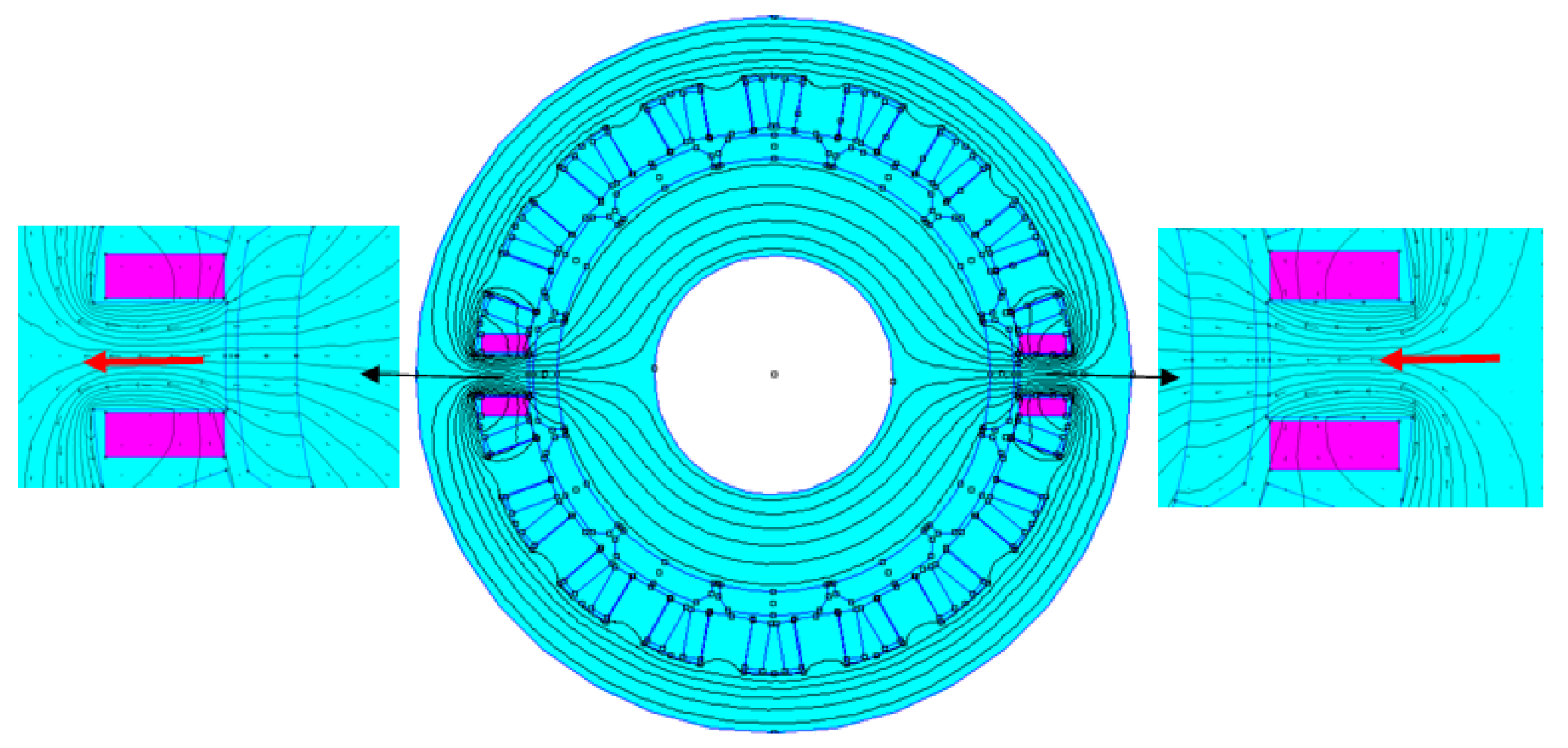
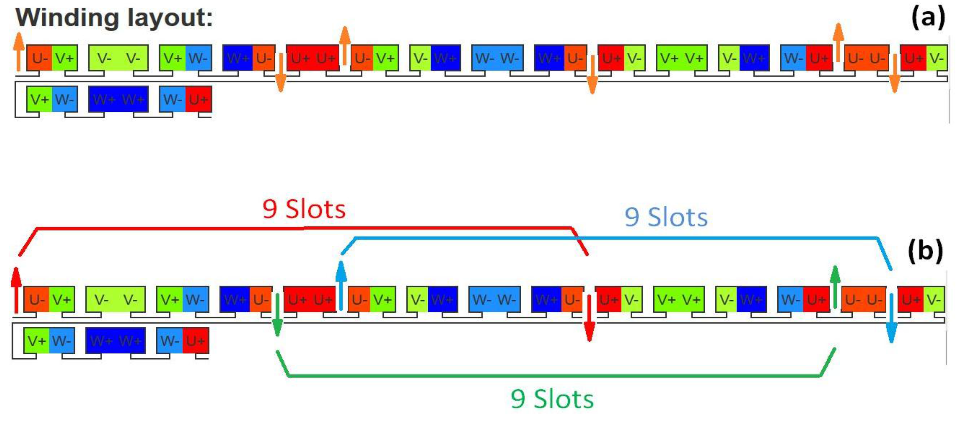
5.2. A Real Structure Using These Properties

A double-star generator with permanent magnets mounted on the surface of the rotor has been designed. It uses the FSCW, has 12 slots and 10 poles. As the numbers of poles (Np) and slots (Ns) are in accordance with one of the main design rules (Ns − Np = ±2), the winding factor is high. Thereafter, using this structure, the mutual inductance between the stars can be calculated. The simulation is presented in Figure 11; the mutual inductance is below 4.4% of the self-inductance. This result is compared with values usually met in the machines which are using the distributed windings. In these machines, the average amount of M/L is usually greater than 30%.
Figure 11. Presentation of the double-star machine, with 10 poles, 12 slots and permanent magnet generator, which corresponds to the first application of the method. The resulting machine presents a very low mutual inductance between the phases and the stars. In addition, in Figure 11a,b, the windings layout for the two stars is shown.
Machines 03 00123 g011
Regarding the flux circulation in the core, one design rule can be summarized. The mutual inductance mitigation can be obtained as soon as the coils of the same phase are changing periodically the direction of the magnetic flux. This rule is presented in Figure 12a. If the direction of the magnetic flux is not alternated, as shown in Figure 12b, the overall effect increases the mutual inductance. In Figure 12a, the machine has 12 slots and 26 poles. In Figure 12b, the machine has 18 slots and 12 poles. In the first case (Figure 12a), the flux direction is alternated and flux mitigation in adjacent coils is realized. The mutual inductance is low. In Figure 12b, no direction of flux is alternated. There is no flux mitigation in the adjacent teeth. This design corresponds to the worst situation; it increases the mutual inductance.
Design tools exist for the FSCW [14]; some of them are free and accessible on the web [15].In using such tools, a machine with 14 poles and 18 slots is examined. In the first step, we select all the coils of one phase (+U, −U) or (−U, +U). In the second step, we focus on the drawing of the magnetic flux direction in each tooth (Written in red, Figure 13a). Note that the magnetic field directions are alternated. Thereafter, it also appears that all the coils have another coil facing them, which mitigates the magnetic fluxes they produce in the adjacent teeth. As there are 18 slots, a coil with an alternated direction in the magnetic field will be found after 18/2 = 9 slots. Such a requirement is obtained (Figure 13b). There is a coil (−U, +U) that follows the coil (+U, −U) after 9 slots. This windings structure has low mutual inductance.
Figure 12. The flux circulation in a machine with 12 slots and 26 poles mitigates the mutual inductance in the adjacent teeth (a); unfortunately, the flux circulation in a machine with 18 slots and 12 poles dramatically increases the mutual inductance in adjacent teeth (b); only the structure (a) complies with the design rule. Any coil (+U, −U) is coupled with a coil (−U, +U) to close the flux path in a favourable manner.
Machines 03 00123 g012
Figure 13. Application of the design rule on a machine with 18 slots and 14 poles. In (a), the direction of the magnetic field is alternated; in (b), the magnetic fluxes generated by the coils cancel each other in the adjacent coils.
Machines 03 00123 g013
Hence, with this last simulation, (Figure 14) the mutual inductance between two phases is low. M/L, it is less than 7%. The total magnetic flux in one tooth when its coil is powered is 0.0108 Wb and the total magnetic flux in one adjacent tooth is less than 0.00075 Wb. It will not be possible to set the flux in all the adjacent teeth to 0. This means that M/L will never be equal to 0. In fact, manufactured machines with M/L equal or greater than 30% can rotate. They must be designed with caution and time-consuming simulations are done to evaluate the impact of the current ripples on the behaviour of the machine [1]. Sometimes, the increase of switching frequency in the inverters can mitigate the current ripple [16] but such a mitigation of the mutual inductance (here divided by 5 in front of an average amount of 30%–35%) will not be obtained by an increase in the switching frequency.
Figure 14. The distribution of the magnetic flux circulation is shown when phase U is powered (a). In (b), the flux along a half circle passing through the teeth.
Machines 03 00123 g014

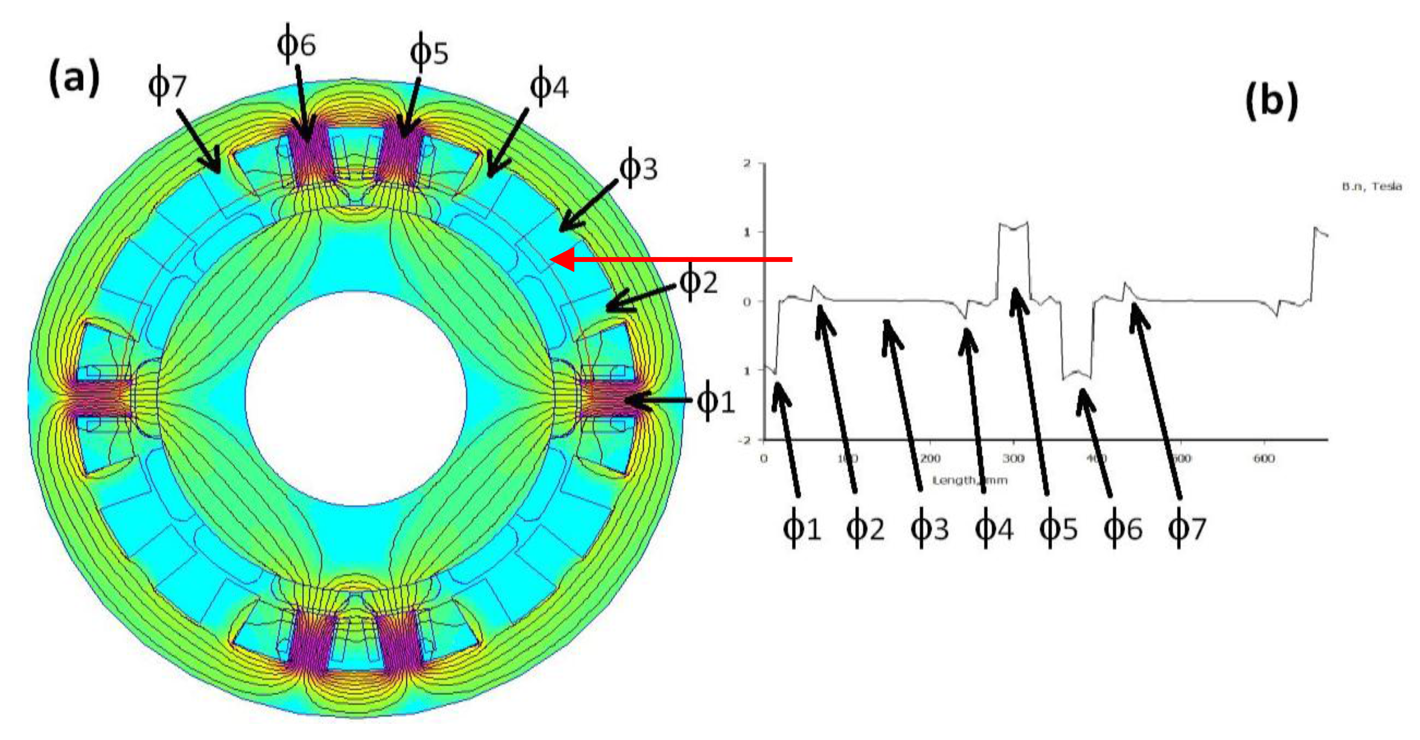
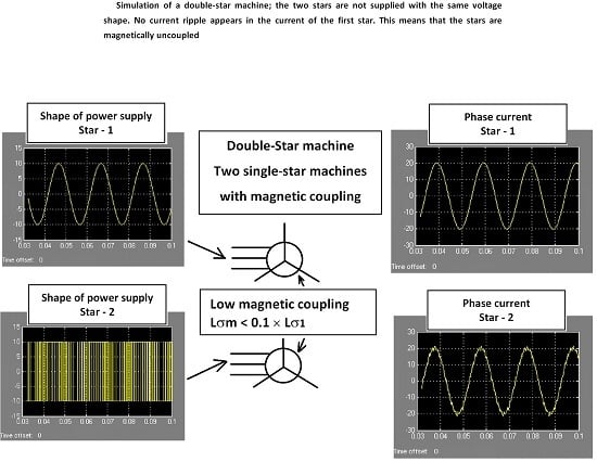
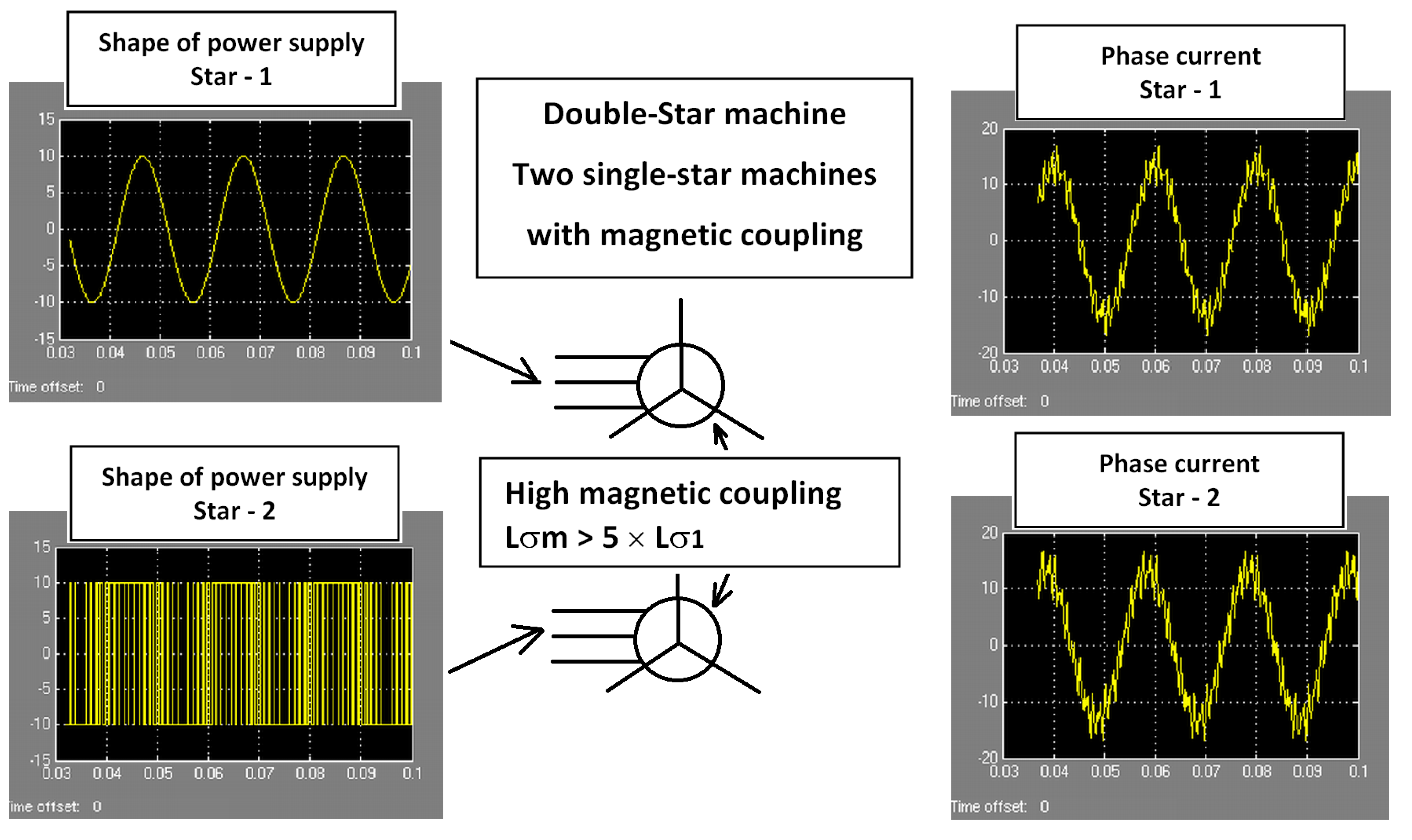
5.3. Simulations Which Validate the Proposed Method

During 1999, N. Moubayed has established the link between the current ripples and the amount of mutual inductance when a double-star machine is fed by power inverters [4]. Using simulations based on the d-q model of a synchronous machine, it can be shown the positive impact in magnetic coupling if the mutual inductance is low (Figure 15). Two machines will be compared. The first one, named MACHINE-1, is a conventional three-phase double-star machine with a large amount of mutual inductance. The second one, named MACHINE-2, is a double-star machine which uses FSCW and respects the design rule presented above. The amount of mutual inductance is low. Using MatLab simulations it is possible to apply two different supplies. The first star can be associated to a pure sinusoidal three-phase supply and the second star can be associated to a PWM supply. With a low magnetic coupling between stars, no disturbance should be observed on the current of the first star. In the first simulation, presented in Figure 16, the magnetic coupling between the stars is high (Lσm) > 5 × (Lσ1) and Lσ1 = Lσ2. The conventional machines have a great magnetic coupling. Hence, caution must be taken when such a machine is designed [1]. In Figure 17, the magnetic coupling is low (Lσm) < 0.1 × (Lσ1) and Lσ1 = Lσ2. The machines using FSCW and following the design rule have a lower magnetic coupling. These machines can be assumed to be magnetically decoupled and sharing the same stator.
Figure 15. Model of a synchronous machine in d-q axis. Lσm can be compared to (Ms-Msr) and Lσ1 or Lσ2 can be compared to (Ls-Ms) in Figure 2. Lσm has the same impact on the current ripple if the machine is supplied by VSI.
Machines 03 00123 g015aMachines 03 00123 g015b
Figure 16. Simulation of a synchronous double-star machine; the two stars are not supplied with the same voltage shape. Current ripples appear in the current associated to the first star. This means that the stars are not magnetically decoupled.
Machines 03 00123 g016
Figure 17. Simulation of a double-star machine; the two stars are not supplied with the same voltage shape. No current ripple appears in the current of the first star. This means that the stars are magnetically uncoupled.
Machines 03 00123 g017

6. Conclusions

Generators with permanent magnets are used in renewable energy, especially generators used in wind power generation. The new generators are now machines with high polarity, operating at low speed, without a gearbox (direct drive mechanism). Some manufacturers have launched studies about the use of FSCW. This technology can offer higher power densities. However, the studied machines remain prototypes and are still in test bench. One of the main objectives of these machines is the efficiency. An average efficiency of 93%–94% or more is expected. The increase in electric power can be managed by an increase in the number of stars. Double-star windings with a 30° electrical split between stars are a well-known topology which can offer low torque ripple and high efficiency. The distributed windings cannot accept this topology if they are coupled with VSIs, as some current ripples can appear and be harmful for the converters. Single-layer windings can create a weak magnetic coupling but also have drawbacks: they decrease the efficiency. In this article, investigations have been done with double-layer windings in order to find a method which is able to mitigate the magnetic coupling between stars. A design rule has been established and is able to characterize the quality of magnetic coupling in a double-layer configuration. The use of multi-star windings can also increase reliability. To ensure reliability it is not necessary to store one costly VSI. Keeping in store a less powerful and cheaper VSI is enough. Even if the FSCW is not the main structure used in renewable energy, prototypes are being tested and herald a new generation of generators [17,18]. The FSCW structure has already been used with success in the design of variable-speed generators [19].

Acknowledgments

The authors acknowledge the French Jeumont-Electric company (Jeumont, France) for their help in selecting the subject of this paper.

Author Contributions

The first author defined the rule which is able to mitigate the mutual inductance in FSCW machines. The second author contributed to the critical revisions of the manuscript.

Conflicts of Interest

The authors declare no conflict of interest.

References

  1. Tessarolo, A. Modeling and Analysis of Multiphase Electrical Machines for High-Power Applications. Ph.D. Thesis, The University of Trieste, Trieste, Italy, 2011. [Google Scholar]
  2. El-Refaie, A.M. Fractional-Slot Concentrated-Windings Synchronous Permanent Magnet Machines: Opportunities and Challenges. IEEE Trans. Ind. Electron. 2010, 57, 107–121. [Google Scholar] [CrossRef]
  3. Lipo, T.A. A d-q Model for Six-Phase Induction Machines. In Proceedings of the International Conference of Electrical Machines (ICEM), Athens, Greece, 15–17 September 1980; pp. 860–867.
  4. Moubayed, N.; Meibody-Tabar, F.; Davat, B.; Rasoanarivo, I. Conditions of Safely Supplying of DSIM by Two PWM-VSI. In Proceedings of the 8th European Conference on Power Electronics and Applications (EPE’99), Lausanne, Switzerland, 7–9 September 1999.
  5. Kallio, S. Modeling and Parameter Estimation of Double-Star Permanent Magnet Synchronous Machines. Ph.D. Thesis, The Lappeenranta University of Technology, Lappeenranta, Finland, 2014. [Google Scholar]
  6. Martinez, D. Design of a Permanent-Magnet Synchronous Machine with Non-Overlapping Concentrated Windings for the Shell Eco Marathon Urban Prototype. Master’s Thesis, The KTH Electrical Engineering, Stockholm, Sweden, 2012. [Google Scholar]
  7. Seo, U.-J.; Chun, Y.-D.; Choi, J.-H.; Chung, S.-U.; Han, P.-W.; Koo, D.-H. General Characteristic of Fractional Slot Double Layer Concentrated Windings Synchronous Machines. J. Electr. Eng. Technol. 2013, 8, 282–287. [Google Scholar] [CrossRef]
  8. Zheng, P.; Wu, F.; Lei, Y.; Sui, Y.; Yu, B. Investigation of a Novel 24-Slot/14-Pole Six-Phase Fault-Tolerant Modular Permanent-Magnet In-Wheel Motor for Electric Vehicles. Energies 2013, 6, 4980–5002. [Google Scholar] [CrossRef]
  9. Zhu, Z.Q. Fractional Slot Permanent Magnet Brushless Machines and Drives for Electric and Hybrid Propulsion System. COMPEL Int. J. Comput. Math. Electr. Electronic Eng. 2011, 30, 9–31. [Google Scholar]
  10. Meeker, D. FEMM, Finite Element Method Magnetics. Available online: http://www.femm.info/wiki/Download (accessed on 31 January 2015).
  11. Barcaro, M.; Bianchi, N.; Magnussen, F. Analysis and Test of a dual Three-Phase 12 Slot 10 pole Permanent Magnet Motor. IEEE Trans. Ind. Appl. 2010, 46, 2355–2362. [Google Scholar] [CrossRef]
  12. Weizhon, F. Fermanent Magnet Synchronous Machines with Fractional Slot and Concentrated Winding Configuration. Ph.D. Thesis, The University of Cranfield, Bedford, UK, 2011. [Google Scholar]
  13. Krall, R.; Krenn, J.; Weiss, H. Six Phase Permanent Magnet Machine with Fractional Slot Concentrated Windings. In Proceedings of the ECCE, The 15th European Conference on Power Electronics and Applications (EPE’13), Lille, France, 3–5 September 2013; pp. 26–31.
  14. Hwang, C.-C.; Liu, C.T.; Chang, H.-C. An interactive design of the winding layout in permanent magnet machines. Rom. Rev. Tech. Sci. Electr. Ser. Energ. 2011, 56, 387–395. [Google Scholar]
  15. EMETOR—Electric Motor Winding Calculator, Website Offering Free Online Tools for the Design of FSCW. You can Investigate Integer-Slot, Fractional-Slot and Concentrated Windings, both Single and Double Layer Windings, Calculate Winding Factor, Display the Winding Layout and Harmonic Spectrum. Available online: https://www.emetor.com/edit/windings/ (Accessed on 31 January 2015).
  16. Moubayed, N. Alimentation par Onduleurs de Tension des Machines Multi-Etoiles. Ph.D. Thesis, The Institut National Polytechnique de Loraine, Génie Electrique, Nancy, France, 1999. [Google Scholar]
  17. Thomas, K.; Grable, M.; Yuen, K.; Leijon, M. A Permanent Magnet Generator for Energy Conversion from Marine Currents: No Load and Load Experiments. ISRN Renew. Energy 2012, 2012. [Google Scholar] [CrossRef]
  18. Mashimo, A.; Hoshi, M.; Umeda, M. Permanent Magnet Synchronous Generator for Wind-Power Generation. Fuji Electr. Rev. 2013, 59, 130–134. [Google Scholar]
  19. Boldea, I. Variable Speed Generators. In The Electric Generators Handbook; Taylor & Francis Group: Abingdon, UK, 2005. [Google Scholar]

