Extrusion Roller Imprinting with a Variotherm Belt Mold

1
Department of Mechanical & Industrial Engineering, University of Massachusetts Amherst, Amherst, MA 01003, USA
2
School of Materials Science and Engineering, Georgia Institute of Technology, Atlanta, GA 30332, USA
*
Author to whom correspondence should be addressed.
Machines 2014, 2(4), 299-311; https://doi.org/10.3390/machines2040299
Submission received: 28 May 2014
/
Revised: 13 October 2014
/
Accepted: 21 November 2014
/
Published: 18 December 2014
(This article belongs to the Special Issue Advances and Challenges in Manufacturing Automation)
Abstract
:Although many precision fabrication techniques have demonstrated the ability to produce microstructures and micro-devices with sub 100 nm accuracy, we are yet to see a scalable manufacturing process for large-area production. One promising solution to scalable micro- and nanofabrication is thermal roller imprinting. However, existing investigations on thermal roller imprinting revealed poor pattern transfer fidelity, especially for high aspect ratio features. The standard roller imprinting process suffers from the lack of an effective holding and cooling stage so that the adverse effects from the viscoelastic nature of polymers are not managed. To rectify this problem and further improve the production rate, a new extrusion roller imprinting process with a variotherm belt mold is designed, and its prototype was established at a laboratory scale. The process testing results demonstrate that a 30 μm sawtooth pattern can be faithfully transferred to extruded polyethylene film at take-up speeds higher than 10 m/min. The results are promising in that microfeatures or even nanofeatures may be successfully replicated by a robust and scalable industrial process suitable for large-area, continuous production.

1. Introduction
Roll-to-roll imprinting, or simply roller imprinting, represents a category of micro-replication processes where roll-to-roll engagements are utilized for continuous replication of micro- and nanostructures onto polymer substrates. Due to increasing interest in scalable micro- and nanofabrication, considerable efforts have been made in the past decade in development of enabling processes for roller imprinting [1,2]. These processes can be generally separated into two groups: thermoplastic roller imprinting and UV-curing roller imprinting. As the names suggest, the former involves a thermoplastic polymer as a replicating material while the latter uses a UV-curable resin.
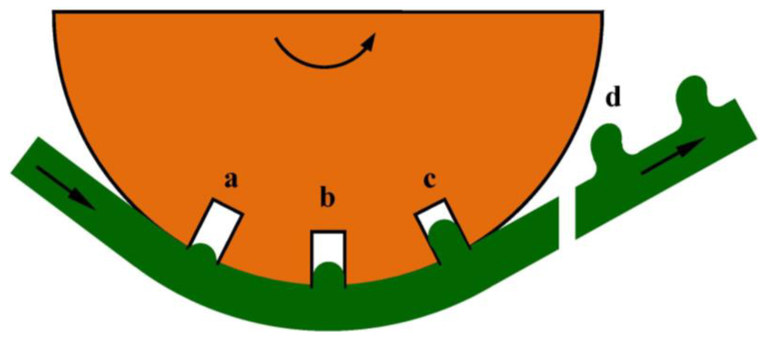
Of the two types of imprinting materials, thermoplastic polymers are of particular interest to the industry owing to their wide availability and versatile properties. However, existing investigations on thermoplastic roller imprinting revealed poor pattern transfer fidelity, especially for high-aspect-ratio features. The standard roller imprinting process involves a constant-temperature roller mold for imprinting, and this leads to an undesirable thermomechanical history for the imprinting polymer. Due to the lack of effective cooling, the polymer film leaves the roller mold at a temperature higher than the polymer softening temperature. The embossed structures are thus subjected to unwanted viscoelastic recovery after pattern releasing. Because of viscoelastic recovery, the imprinted surface features are distorted and minimized and, in the worst case, converge to a flat surface. Figure 1 illustrates the formation of replication deflects in thermoplastic roller imprinting.
Figure 1.
Formation of replication defects during thermal roller imprinting: (a) engaging; (b) imprinting; (c) incompletely filled cavity; (d) distorted structures.
Figure 1.
Formation of replication defects during thermal roller imprinting: (a) engaging; (b) imprinting; (c) incompletely filled cavity; (d) distorted structures.
Work has previously been conducted to develop methods for more effective thermal control in roller imprinting. Michaeli and coworkers [3] proposed to develop tools for dynamically heating the embossing (or imprinting) roller and providing different temperatures over the circumference of the roller. With such an embossing roller, the film can be embossed (or imprinted) in a high temperature zone and then cooled in a low temperature zone on the same roller. In the follow-up studies [4,5], Michaeli and coworkers developed two technical approaches—induction heating and radiation heating—for variothermally heating the embossing roller, and successfully replicated different types of microstructures in continuous production. Despite the promising results, the primary limiting factor in this process is the large thermal mass of the roller mold. Due to the substantial thermal inertia, rapidly heating and cooling the roller surface and achieving high take-up speed is challenging. A possible alternative to directly heating and cooling the roller is to create a separate belt mold. This belt mold has a low thermal mass and can therefore be rapidly heated and cooled. In fact, thin-shell molds have been successfully used in flat-mold hot embossing [6,7]. Contact heating is particularly effective in heating such shell molds [8]. Similar ideas may be adapted to roller imprinting for heating belt molds. This may be accomplished by employment of multiple pairs of rollers [1,9]: for example, one pair of rollers for heating the belt mold and a second pair of rollers for cooling the belt mold. Besides contact heating, active heating methods can also be utilized to heat the belt mold. Fagan et al. [10] demonstrated that a belt mold can be rapidly heated by induction heating, and a temperature difference of more than 200 °C can be achieved in continuous roller imprinting. With this imprinting system, they were able to replicate both micrometer and sub-micrometer patterns at a film feed speed exceeding 1.5 m/min. In comparison with heating of the imprinting roller, heating of the belt mold benefits from the low thermal mass and the long path of the belt mold. Therefore, flexible manufacturing systems may be developed for demanding applications in micro- and nanofabrication.
Recently, there also emerges an interest in integrating film extrusion with roller imprinting, leading to the development of the extrusion roller imprinting process [4,11,12,13]. It is believed that a number of advantages result from such system integration:
- (1)
- Particle contaminant to the web surface is minimized in the single-step extrusion and imprinting process.
- (2)
- Functional materials can be in situ formulated to meet special requirements in specific applications.
- (3)
- Reheating of the polymer film is not necessary. This mitigates problems caused by the reheating process, e.g., film wrinkling.
- (4)
- Film tension and temperature can be better controlled. This can lead to reduced residual stress in the imprinted film as well as more uniform properties.
The extrusion roller imprinting process bears close similarities with classical film extrusion and post processing. It utilizes the typical viscoelastic behavior of polymer for achieving the optimal process dynamics. The extrusion speed and the roller speed can be independently controlled yet synchronized so as to impart a suitable tension and microstructural development on the film. Due to these similarities, the broad knowledge base developed in conventional polymer processing may be adapted to the new micro- and nanofabrication process.
In this work, we designed and constructed a new extrusion roller imprinting system with a variotherm belt mold and tested its suitability for continuous microfabrication. The major components of the system include an extruder, a belt mold, a roll-to-roll setup, and an induction heating unit. The extruded polymer film is imprinted between the belt mold and the pressure roller. Due to the variotherm capability, the imprinted film is effectively cooled before it is released from the belt mold. The feasibility of the overall manufacturing system was tested, and continuous production of microstructured polyethylene film was established.
2. Design of Variotherm Extrusion Roller Imprinting Process
A simple filling model can be established to understand the difficulty in micro- and nanocavity filling during thermal roll imprinting. By assuming constant viscosity and pressure driven flow, one can arrive at the following equation governing the filling process,
where
is cavity fill ratio, p is pressure, t is time, T is temperature, a is representative cavity size and η is viscosity that is temperature dependent. This equation reveals that to improve cavity fill, one has to increase contact pressure and contact time and reduce viscosity. Qualitatively speaking, the viscosity decreases with increase of temperature. Since suitable contact pressure is typically limited to a few MPas and the cavity size is fixed in a specific case, the remaining parameters to adjust are temperature and contact time. Therefore, it becomes apparent that both temperature and contact time need to be raised to achieve better replication. Besides incorporation of an effective filling stage, it is also important to create a sufficient holding stage so that viscoelastic recovery after pattern release can be minimized. This requires the imprint film be cooled under imprinting pressure and solidified or vitrified before departure from the imprinting roll.
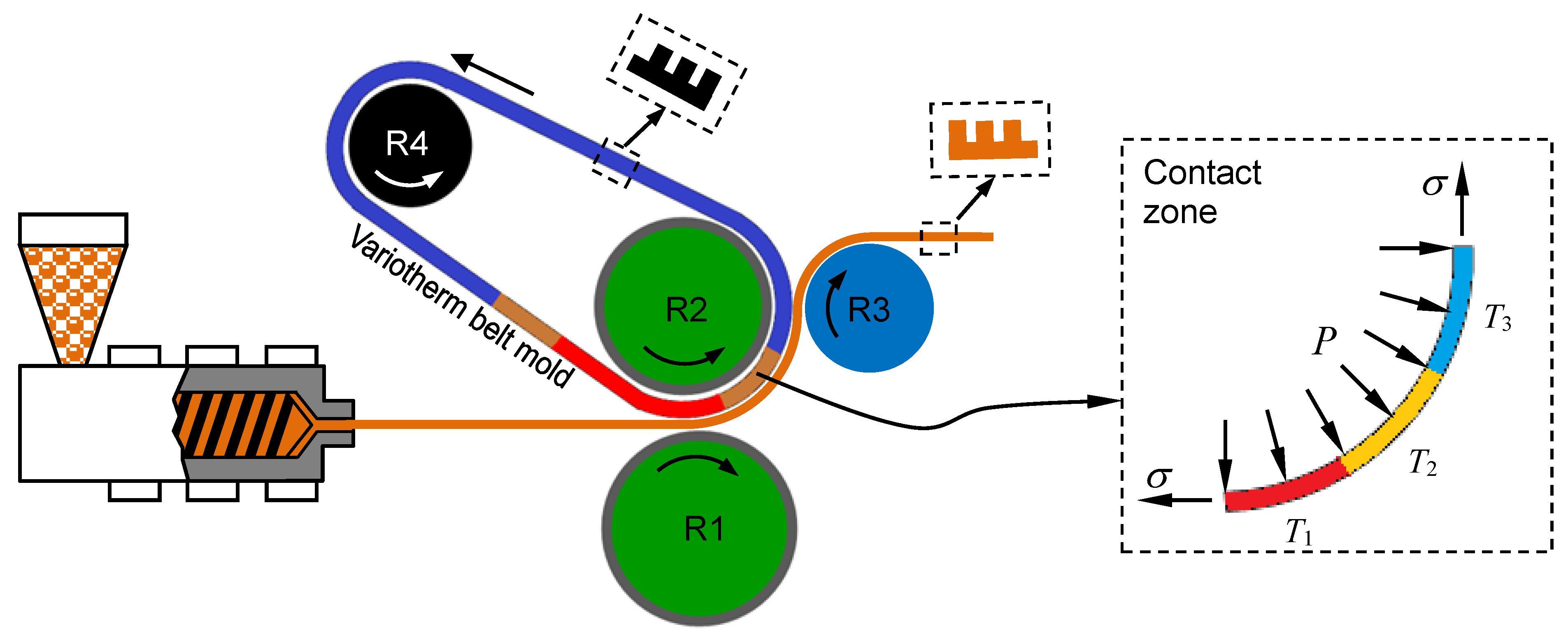
The design of the variotherm extrusion roller imprinting (VERI) process is schematically illustrated in Figure 2. This process is specially designed to create a suitable thermomechanical history for continuous thermal imprinting. It is characterized by several novel features including a variotherm module for controlling the heating and cooling of the polymer film and an endless belt mold for improving contact and creating an effective holding process, as elaborated below.
Figure 2.
Schematic setup of variotherm extrusion roller imprinting. The extended contact zone is highlighted on the right, showing decreasing temperature from T1–T3, and a pressure applied over the entire contact area.
Figure 2.
Schematic setup of variotherm extrusion roller imprinting. The extended contact zone is highlighted on the right, showing decreasing temperature from T1–T3, and a pressure applied over the entire contact area.

- An extrusion unit for melting and mixing the polymer(s). This element allows functional materials to be in situ compounded during micro- and nanofabrication. Moreover, with the extruder, reheating of the polymer film is not required. This mitigates problems caused by the reheating process (e.g., film wrinkling, difficulty in tension control, etc.). Furthermore, the extrusion process allows a film with a desired structure and morphology suitable for roll imprinting to be produced. This can be done by in situ control of the jet stretch, drawing and heat setting stages of the film formation process.
- A belt mold for enlarged contact between the polymer film and the master pattern. Standard roller imprinting processes rely on a small contact zone for applying pressure to the polymer film. This results in a short contact time for microcavity filling, causing short shot or underfilled cavities. The belt mold provides a possible solution to this problem by producing pressure in a large contact zone.
- A rapid heating and cooling capability. The belt mold is heated to the polymer softening/melting temperature before reaching the imprinting zone and then gradually cooled along the path of the polymer film. This not only provides a hot mold for filling micro- and nanocavities but also offers a cold mold for cooling the polymer under holding pressure.
The critical section in the VERI setup is the contact zone, as highlighted in Figure 2. Besides the normal imprinting pressure applied between R1 and R2, contact pressure is generated in the entire contact zone due to the tension applied in the extruded viscoelastic film. To generate high contact pressure, an additional carrying film can be placed underneath the extruded film so that high film tension can be applied. The enlarged pressure zone is considered useful for high-speed imprinting since the polymer gains more time to fill the cavity. The temperature in the contact zone decreases along the film path. This is also an important feature of the new process. The decreasing temperature emulates the typical thermoplastic protocol needed for precision patterning, as used by injection molding and compression molding. The polymer will be deformed primarily in the high temperature zone, T1, then held under pressure at reduced temperatures along the polymer path, and finally cooled and released from the belt. By incorporating an in-mold holding and cooling stage, the undesired viscoelastic effects can be suppressed. This design of the thermomechanical history is considered necessary for precision micro/nano patterning, particularly at high-speed production.
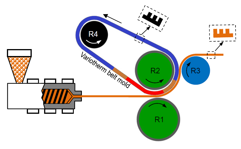
3. Rapid Thermal Cycling of Belt Mold
For flat molds, thermoplastics have been extensively used as substrate receivers for transferring micro- and nanostructures. The resulting process is often referred to as hot imprinting or hot embossing. As implied by its name, hot imprinting relies on a heated mold at temperature above the glass transition temperature (Tg) for amorphous polymer or the melting temperature (Tm) for semicrystalline polymer. This elevated temperature is necessary for filling micro- and nanocavities, since the polymer melt would otherwise rapidly freeze or vitrify against a cold mold, leaving an unfilled cavity. After the imprinting stage, the mold is cooled for pattern releasing. Thermal cycling of a hot imprinting mold is a time consuming process, and cycle times exceeding several minutes are common in hot embossing and imprinting [14].
The necessity for thermal cycling in flat-mold imprinting helps understand the limitation of roller-based processes in thermoplastic patterning. Due to its large thermal mass, a roller mold is difficult to be thermally cycled. As a result, when a roller mold is used in patterning, the common practice is to set the mold to a constant temperature [15,16]. The lack of an in-mold cooling stage is the primary reason why roller imprinting processes for thermoplastics have only demonstrated limited capability in precision micro/nano patterning. Up to now, limited success has only been demonstrated for roller imprinting of microstructures with relatively low aspect ratios [1].
A number of efforts have been reported to improve the thermal cycling efficiency in flat-mold hot imprinting. The reported methods include contact heating, fluid heating, infrared heating, ultrasonic heating, high frequency and induction heating, and resistive heating. In particular, Kimerling et al. [14] showed that with high-frequency heating, short cycle times, about 10 seconds, can be achieved in hot imprinting. With proper modification, these methods may be adapted to heating of the belt mold.
Yao et al. [8] have discussed the general strategies for design and fabrication of a rapidly heatable and coolable mold. The two main building blocks are a low-thermal-mass mold and a means for rapid heating. The belt mold design, rather than use of a roller mold, conforms well to the first requirement due to the extremely small thermal mass carried by the belt. The long strip design and the thin wall section of the belt also permit some of the above-mentioned heating methods to be more effectively implemented. The objective is to determine a robust heating and cooling solution in a continuous process. The induction heating method stands out for this application due to its effectiveness and versatility compared with other methods.
Figure 3 shows a setup involving induction heating. By passing high-frequency current in the induction coil, eddy current is induced in the belt for rapid heating. This so-called skin effect [17] is useful for generating electrical current only concentrated at the surface of the belt, thus facilitating effective resistive heating. Since induction heating is not energy limited, rapid heating rates can be readily achieved by raising the heating power. The heated belt then engages with a pair of pressure rollers, R1 and R2, set at a low temperature. The belt starts to cool upon wrapping around the pressure roller R2. In this case, cooling is mainly facilitated by heat conduction. Since both the belt mold and the main pressure roller, R2, are preferably made of metal, the contact cooling process is expected to be fast. After leaving R2, the belt mold is under air cooling. If necessary, one can enhance cooling between R2 and R4 by employing forced convection.
Figure 3.
Induction heating of belt mold.

The cooling time tc required for the surface of a belt to reach temperature Tf can be estimated by
where H is the belt thickness, Ti is the initial temperature, Tr is the roller temperature, and α is the diffusivity. For a representative case of a 0.5 mm thick nickel belt with α = 2.3 × 10⁻⁵ m2/s, Ti = 225 °C, Tf = 125 °C, and Tr = 25 °C, the calculated cooling time is on the order of 0.1 s. On the other hand, the time needed to fill an aspect ratio of 1 is calculated to be 0.6 s according to Equation (1) assuming representative conditions of η = 105 Pa-s and p = 1 MPa. It, therefore, seems that the cooling process is too fast to achieve filling of high-aspect-ratio features. This can be rectified by increasing the belt thickness and/or adjusting the contact condition between the belt and the pressure roller. For example, a thermal coating can be applied to the main pressure roller that directly contacts with the belt mold, as illustrated in Figure 3. In reality, there is always a contact interface between the belt and the roller even with no coating applied, and this greatly impedes the cooling process.
4. Experimental Investigation
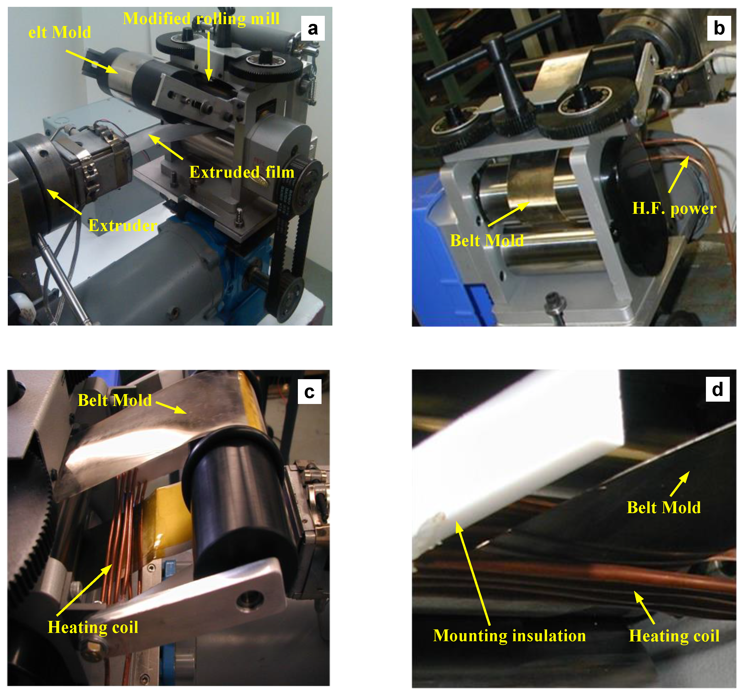
A variotherm extrusion roller imprinting setup was established at laboratory scale for feasibility test. The major components in the setup include a laboratory single-screw extruder, a rolling mill, and an induction heating unit. A belt mold and an induction heating coil were also designed and fabricated. All these components were integrated to yield a workable system for extrusion roller imprinting, as shown in Figure 4. The details for the setup are elaborated as follows.
Figure 4.
Experimental setup for variotherm extrusion roller imprinting: (a) view from the extruder side; (b) view from the rolling mill side; (c) belt mold and heating coil; (d) close view of heating coil.
Figure 4.
Experimental setup for variotherm extrusion roller imprinting: (a) view from the extruder side; (b) view from the rolling mill side; (c) belt mold and heating coil; (d) close view of heating coil.

The single-screw extruder used is a C. W. BraBender Type 120-25HC four-zone 1.25 inch extruder driven by a 7½ Horsepower DC motor through a 17:1 reduction gearbox. The speed of the motor is controlled by a General Electric GP100 motor control unit. The temperature of each zone of the extruder barrel is controlled by a PID controller connected to electric resistance heaters and a high-pressure air solenoid valve for cooling. The extruder is equipped with a standard screw with an L/D ratio of 25:1 and a compression ratio of 2:1. A slit die with a 25.4 mm × 0.254 mm opening was designed and fabricated. The finished die is shown in Figure 5.
Figure 5.
A slit die for film extrusion: (a) die components; (b) die assembly.
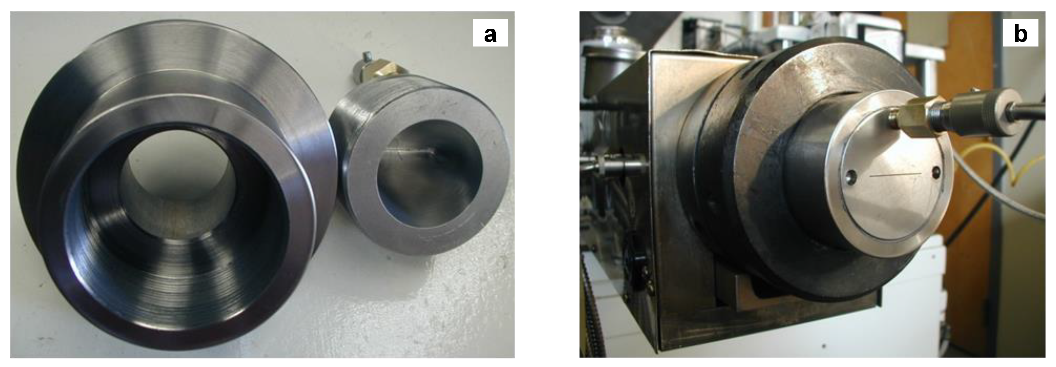
A jeweler’s rolling mill (Model: Pepetools 189.00) with 139 mm wide, 65 mm diameter flat rollers was modified and retrofitted to the VERI setup. In the modified rolling mill, the upper roller is driven by a variable speed, gearhead DC motor (maximum 40 RPM) and coupled to an engaging roller mounted on an external shaft. This pair of engaging rollers drives the belt mold (refer to R2 and R4 in Figure 2) during continuous roller imprinting. The rollers can be easily removed for installing the belt mold. The upper roller is also the main pressure roller for imprinting the polymer film.
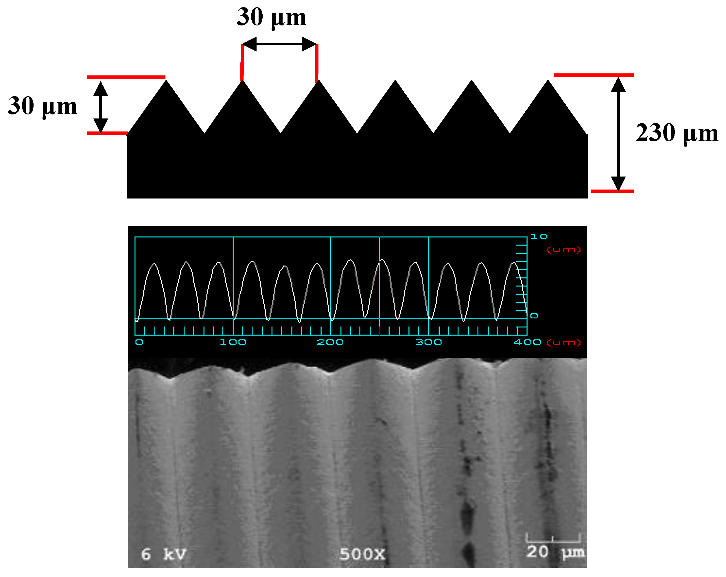
Figure 6.
Sawtooth microfeatures on the belt mold.

A closed-loop flexible belt mold was prepared from electroformed nickel alloy sheets containing sawtooth type features, 30 μm in height and pitch, as shown in Figure 6. Specifically, strips of nickel alloy sheets were assembled together using heat tolerant Kapton® polyimide tape. The completed belt mold is approximately 10 cm wide, 50 cm long, and 250 μm thick. It was finally installed onto the modified rolling mill through the upper roller (Figure 4b).
To heat the belt mold, a closely coupled induction heating (IH) coil (Figure 4d) was designed and built using 3.125 mm OD soft copper tubing. The IH coil is powered by a high-frequency power unit (Model: Nova Star 3H from Ameritherm Inc., Scottsville, NY, USA). This power unit is able to deliver a full power of 3 kW, with a maximum voltage of 220 V and a maximum current of 17 A, over a frequency range of 515 kHz to 1.0 MHz.
Low-density polyethylene (Westlake Chemical EC808 LDPE) was used in the processing tests. The temperatures of the four extruder barrel zones were set to span from 180 to 200 °C. The first zone or feeding zone was set to 180 °C. The second zone was set to 190 °C. The third and fourth zones as well as the die zone were set to 200 °C. The extruded HDPE web exiting the die runs below the IH coil to meet the heated belt mold at the roller nip, then wraps around the belt mold on the upper roller, and finally travels about 70 cm in air to a take-up beam.
The extruder screw was run at 18–20 rpm producing a melt pressure before the die of around 30 MPa. The gap between the lower roller and the belt mold was set to approximately 0.25 mm after the web was running smoothly and the embossed film was produced at a rate of around 10–12 m/min. The speed of the rolling mill was adjusted to match the rate of extrusion and the speed of the take-up beam was adjusted to minimize defects in the extruded film. The temperature of the belt mold was maintained at approximately 210 °C by running the induction heater at 1.6 kW power output and around 190 °C at 1.2 kW. The temperature of the mold was measured right before the belt entered the imprinting nip using a Raytek MI infrared pyrometer—a noncontact thermometer. For reference, the temperature of the mold right before the belt entered the heating coil was also measured. This latter temperature was found to be close to room temperature, indicating that sufficient cooling of the belt was achieved.
Although adjustments in the different speeds and settings of the equipment produced variations in the dimensions of the extruded film, during steady-state operation the imprinted film had a thickness of 0.22 mm and a width of 44 mm.
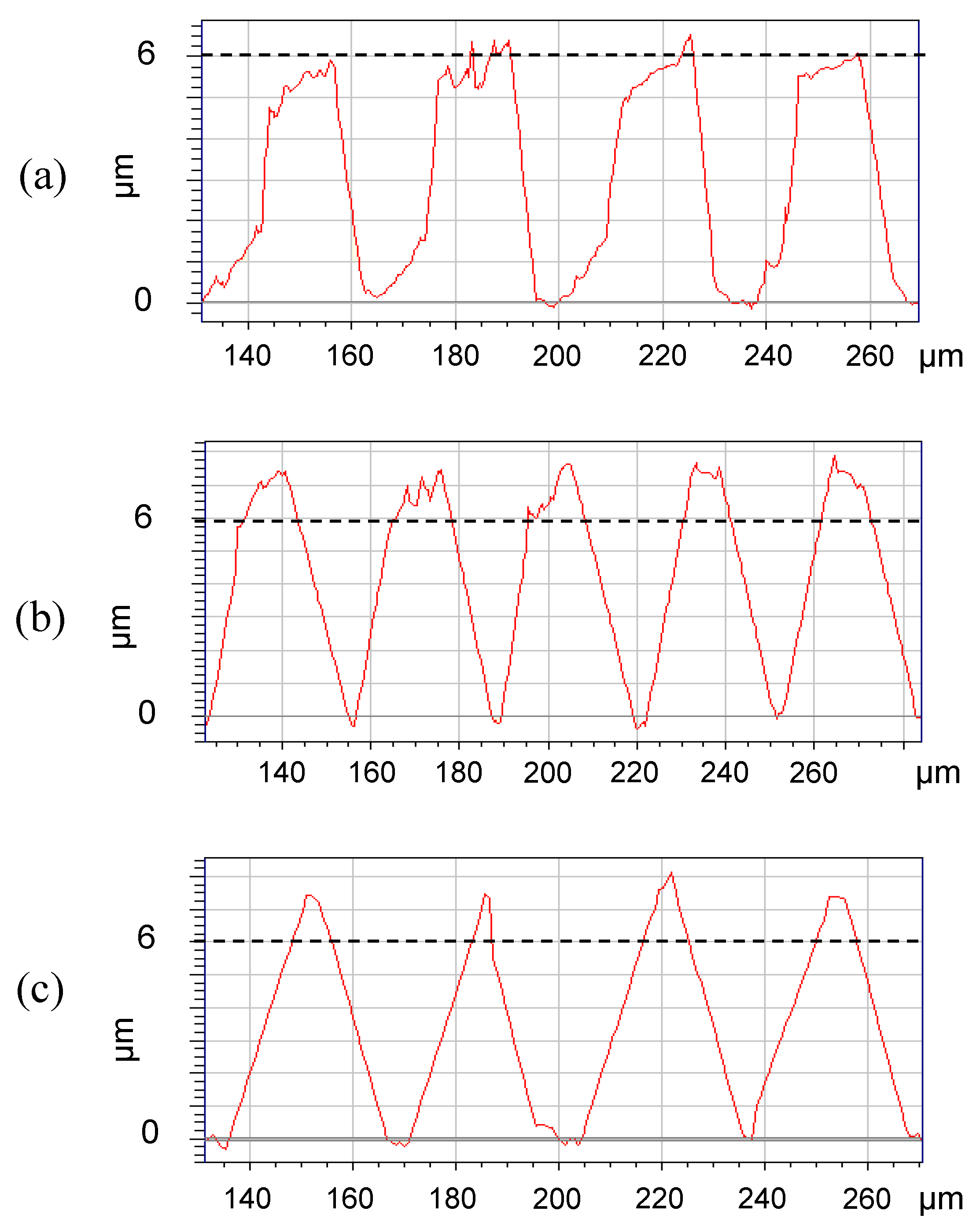
During the test the induction heating unit was turned on and off several times to determine the effect of heating the belt mold. In Figure 7 digital microscopy images of the imprinted web are presented for the cases with no induction heating and with induction heating power set at 1.2 kW and 1.6 kW. The improvement in feature pattern replication with the heating of the ribbon mold by induction heating is apparent in the microscopy images. The difference between using a power setting of 1.2 kW and 1.6 kW can be better seen with the Veeco Dektak Stylus Profilometer. Figure 8 shows the 2D profile and Figure 9 shows the 3D image of the imprinted webs with no induction heating and with induction heating power set at 1.2 kW and 1.6 kW.
Figure 7.
Digital microscopy images for low-density polyethylene (LDPE) films imprinted with (a) no heat; (b) 1.2 kW; and (c) 1.6 kW.
Figure 7.
Digital microscopy images for low-density polyethylene (LDPE) films imprinted with (a) no heat; (b) 1.2 kW; and (c) 1.6 kW.
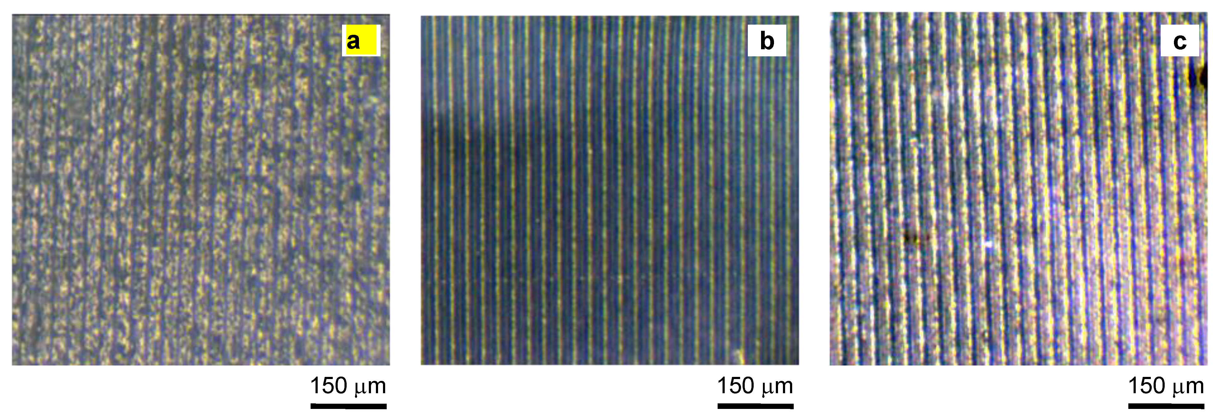
Figure 8.
Veeco Dektak Stylus Profilometry 2D for LDPE films imprinted with (a) no heat; (b) 1.2 kW and (c) 1.6 kW.
Figure 8.
Veeco Dektak Stylus Profilometry 2D for LDPE films imprinted with (a) no heat; (b) 1.2 kW and (c) 1.6 kW.
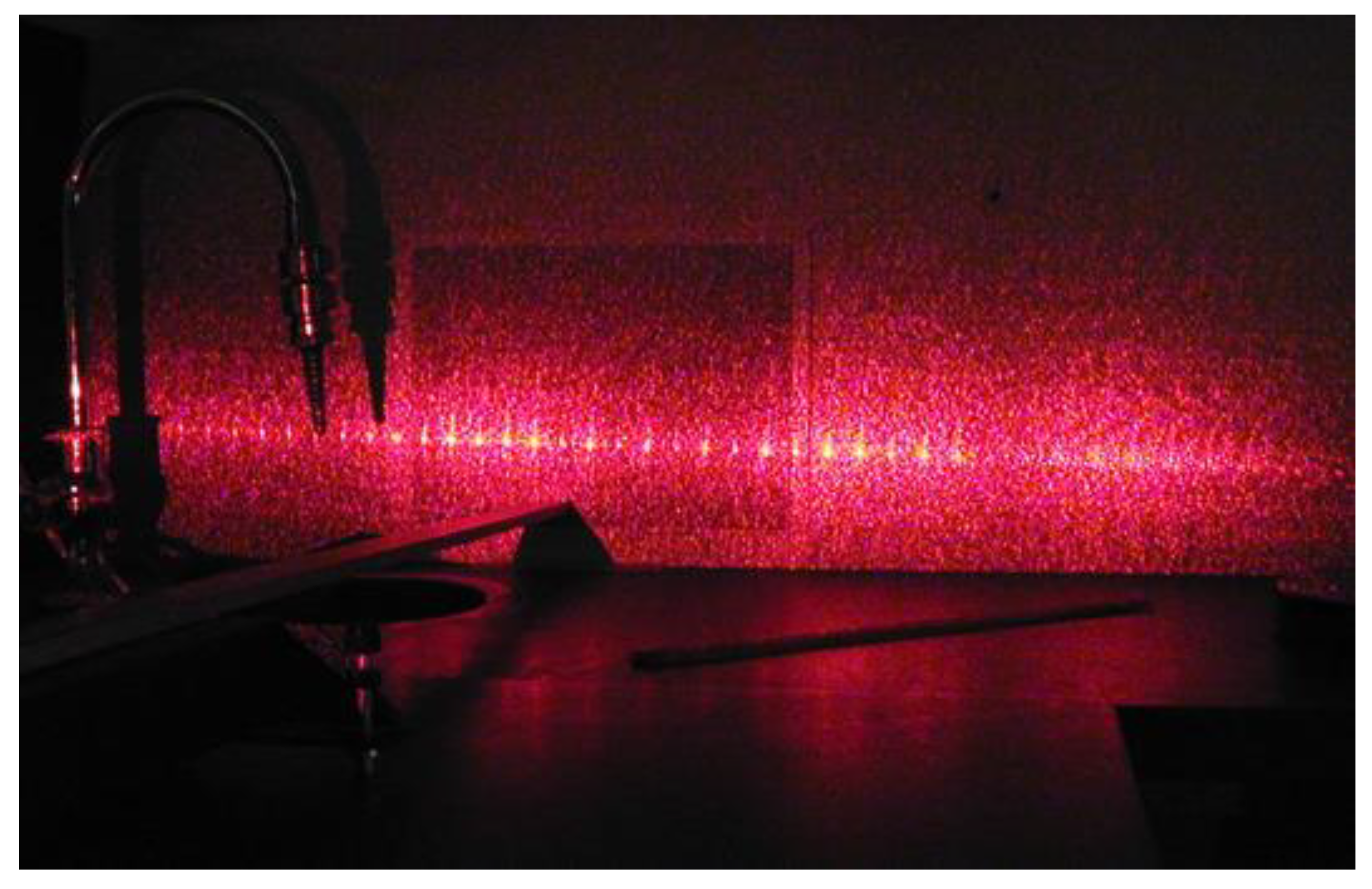
A further analysis of the imprinted extruded film was performed by using a sample of the film as a diffraction grating element with a helium neon laser as seen in Figure 10. With the sample held at a distance of 1 m from the target, the distance between the first order spots was 74 mm indicating a grating space he of 34 µm, which is close to the pitch of the original sawtooth pattern on the belt mold.
Figure 9.
Veeco Dektak Stylus Profilometer 3D for LDPE films imprinted with (a) no heat; (b) 1.2 kW and (c) 1.6 kW.
Figure 9.
Veeco Dektak Stylus Profilometer 3D for LDPE films imprinted with (a) no heat; (b) 1.2 kW and (c) 1.6 kW.
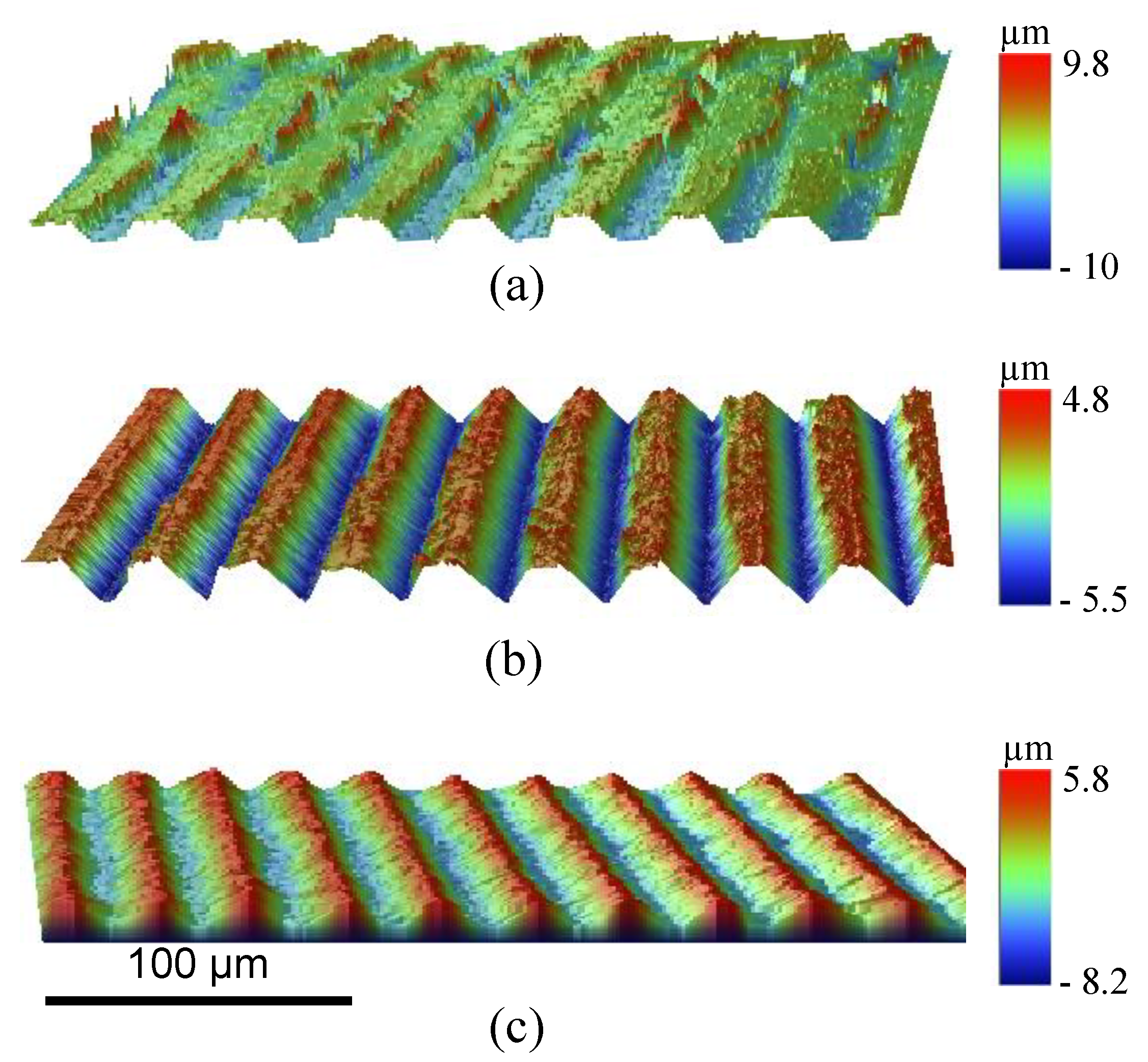
Figure 10.
Diffraction from an imprinted saw-teeth film with a helium neon laser.
In summary, the experimental trials demonstrate that the laboratory VERI system is capable of continuously producing polyethylene film structured with a sawtooth pattern. The system can be operated stably at a high take-up speed exceeding 10 m/min. This rate is considerably higher than that previously reported by the authors [10] on a thermal roller-imprinting system. These results seem promising in that microfeatures can be successfully replicated by a robust and scalable industrial process suitable for large-area, continuous production. The experimental trials also indicate the important effect of the belt mold temperature; belt mold temperature above the polyethylene melting temperature is needed for complete replication of the sawtooth pattern, especially the sharp corners. The feasibility study, although focused on microreplication, also indicates potential applications in nanoreplication. The key process parameters for extrusion roller imprinting, including extrusion speed, feed film temperature, belt mold temperature, and contact pressure can be adjusted in large ranges. With further improvement on heating effectiveness, belt mold design and layout, contact arrangement, and roller configuration, scalable micro- and nano-manufacturing is likely to be achieved.
5. Conclusions
A variotherm extrusion roller imprinting system that is specially designed for continuous production of large-area micro- and nanostructures on polymer substrates is described. The major components of the system include a melt extruder, a variotherm belt mold, a roll-to-roll setup, and an induction heating unit. The extruded polymer film is imprinted between the belt mold and the pressure roller. Due to the variotherm capability, the imprinted film is effectively cooled before it is released from the belt mold, thereby minimizing feature distortion caused by viscoelastic recovery. For our feasibility study, a laboratory setup for extrusion roller imprinting equipped with a variotherm belt mold was constructed. The belt mold can be rapidly heated above 200 °C before reaching the imprinting zone and then rapidly cooled to room temperature after disengaged from the pressure roller. Using this new process, a continuous sawtooth pattern with high replication fidelity can be successfully produced on a polyethylene film at a production rate exceeding 10 m/min. The results show that the belt mold temperature plays a profound role in affecting the replication quality. A belt mold temperature above the polyethylene melting temperature is needed for complete replication of the sawtooth pattern, especially the sharp corners. Other key process parameters include the extrusion speed, the feed film temperature, and the imprinting pressure. With further understanding of the interplay between these process parameters and the replication quality and economics, scalable micromanufacturing or even nanomanufacturing is likely to be achieved.
Acknowledgment
This material is based upon work supported by the National Science Foundation as part of the Center for Hierarchical Manufacturing under Grant Number CMMI-0531171.
Author Contributions
Raymond Frenkel performed the process study and participated in the process design. Byung Kim and Donggang Yao supervised the work and designed the variotherm extrusion roller imprinting process.
Conflicts of Interest
The authors declare no conflicts of interest.
References
- Dumond, J.J.; Low, H.Y. Recent developments and design challenges in continuous roller micro- and nanoimprinting. J. Vac. Sci. Technol. B 2012, 30. [Google Scholar] [CrossRef]
- Peng, L.F.; Deng, Y.J.; Yi, P.Y.; Lai, X.M. Micro hot embossing of thermoplastic polymers: A review. J. Micromech. Microeng. 2014, 24. [Google Scholar] [CrossRef]
- Michaeli, E.H.W.; Fink, B.; Blomer, P. Dynamic controll of roll temperatures. Kunstst. Plast Eur. 2005, 95, 51–53. [Google Scholar]
- Michaeli, W.; Eilbracht, S.; Scharf, M.; Hartmann, C.; Bobzin, K.; Bagcivan, N.; Theiss, S. Application of variothermal heating concepts for the production of microstructured films using the extrusion embossing process. J. Polym. Eng. 2012, 32, 95–101. [Google Scholar] [CrossRef]
- Hopmann, C.; Michaeli, E.H.W.; Eilbracht, S.; Bobzin, K.; Bagcivan, N.; Theiss, S.; Hartmann, C.; Holtkamp, J. Extrusion embossing of hydrophobic films—A study on process characteristics and surface properties. J. Plast. Technol. 2012, 8, 302–330. [Google Scholar]
- Yao, D.G.; Nagarajan, P.; Li, L.; Yi, A.Y. A two-station embossing process for rapid fabrication of surface microstructures on thermoplastic polymers. Polym. Eng. Sci. 2007, 47, 530–539. [Google Scholar] [CrossRef]
- Yao, D.G.; Nagarajan, P.; Li, L.; Yi, A.Y. A strategy for rapid thermal cycling of molds in thermoplastic processing. ASME J. Manuf. Sci. Eng. Trans. 2006, 128, 837–843. [Google Scholar] [CrossRef]
- Yao, D.G.; Chen, S.C.; Kim, B.H. Rapid Thermal Cycling of Injection Molds: An Overview on Technical Approaches and Applications. Adv. Polym. Technol. 2008, 27, 233–255. [Google Scholar] [CrossRef]
- Seo, S.M.; Kim, T.I.; Lee, H.H. Simple fabrication of nanostructure by continuous rigiflex imprinting. Microelectron. Eng. 2007, 84, 567–572. [Google Scholar] [CrossRef]
- Fagan, M.D.; Kim, B.H.; Yao, D.G. A Novel Process for Continuous Thermal Embossing of Large-Area Nanopatterns onto Polymer Films. Adv. Polym. Technol. 2009, 28, 246–256. [Google Scholar] [CrossRef]
- Huang, T.C.; Ciou, J.R.; Huang, P.H.; Hsieh, K.H.; Yang, S.Y. Fast fabrication of integrated surface-relief and particle-diffusing plastic diffuser by use of a hybrid extrusion roller embossing process. Opt. Express 2008, 16, 440–447. [Google Scholar] [CrossRef] [PubMed]
- Jiang, L.T.; Huang, T.C.; Chiu, C.R.; Chang, C.Y.; Yang, S.Y. Fabrication of plastic microlens arrays using hybrid extrusion rolling embossing with a metallic cylinder mold fabricated using dry film resist. Opt. Express 2007, 15, 12088–12094. [Google Scholar] [CrossRef] [PubMed]
- Liu, W.L.; Wu, D.M.; Liu, Y.; Zheng, X.T. The research of the extrusion hot embossing process. Mater. Process. Technol. 2011, 337, 323–327. [Google Scholar]
- Kimerling, T.E.; Liu, W.D.; Kim, B.H.; Yao, D.G. Rapid hot embossing of polymer microfeatures. Microsyst. Technol. Micro Nanosyst. Inf. Storage Process. Syst. 2006, 12, 730–735. [Google Scholar]
- Tan, H.; Gilbertson, A.; Chou, S.Y. Roller nanoimprint lithography. J. Vac. Sci. Technol. B 1998, 16, 3926–3928. [Google Scholar] [CrossRef]
- Liu, S.J.; Chen, W.A. Nanofeatured Anti-Reflective Films Manufactured Using Hot Roller Imprinting and Self-Assembly Nanosphere Lithography. Opt. Laser Technol. 2013, 48, 226–234. [Google Scholar] [CrossRef]
- Rudnew, V.; Loveless, R.; Cook, R.; Black, M. Handbook of Induction Heating; Marcel Dekker, Inc.: New York, NY, USA, 2003. [Google Scholar]
© 2014 by the authors; licensee MDPI, Basel, Switzerland. This article is an open access article distributed under the terms and conditions of the Creative Commons Attribution license (http://creativecommons.org/licenses/by/4.0/).
Share and Cite
MDPI and ACS Style
Frenkel, R.; Kim, B.; Yao, D. Extrusion Roller Imprinting with a Variotherm Belt Mold. Machines 2014, 2, 299-311. https://doi.org/10.3390/machines2040299
AMA Style
Frenkel R, Kim B, Yao D. Extrusion Roller Imprinting with a Variotherm Belt Mold. Machines. 2014; 2(4):299-311. https://doi.org/10.3390/machines2040299
Chicago/Turabian StyleFrenkel, Raymond, Byung Kim, and Donggang Yao. 2014. "Extrusion Roller Imprinting with a Variotherm Belt Mold" Machines 2, no. 4: 299-311. https://doi.org/10.3390/machines2040299