The Arsenic Fault-Pathfinder: A Complementary Tool to Improve Structural Models in Mining


1
Advanced Mining Technology Center (AMTC), FCFM, University of Chile, 8320000 Santiago, Chile
2
Geomechanical Superintendence, Los Bronces Division, Anglo American Chile, 8320000 Santiago, Chile
*
Author to whom correspondence should be addressed.
Minerals 2018, 8(9), 364; https://doi.org/10.3390/min8090364
Submission received: 5 July 2018
/
Revised: 10 August 2018
/
Accepted: 17 August 2018
/
Published: 21 August 2018
(This article belongs to the Section Mineral Deposits)
Abstract
:In a mining operation, the structural model is considered as a first-order data required for planning. During the start-up and in-depth expansion of an operation, whether the case is open-pit or underground, the structural model must be systematically updated because most common failure mechanisms of a rock mass are generally controlled by geological discontinuities. This update represents one of the main responsibilities for structural geologists and mine engineers. For that purpose, our study presents a geochemically-developed tool based on the tridimensional (3-D) distribution of arsenic concentrations, which have been quantified with a very high-density of blast-holes sampling points throughout an open pit operation. Our results show that the arsenic spatial distribution clearly denotes alignments that match with faults that were previously recognized by classical direct mapping techniques. Consequently, the 3-D arsenic distribution can be used to endorse the existence and even more the real persistence of structures as well as the cross-cutting relationships between faults. In conclusion, by linking the arsenic fault-pathfinder tool to direct on field fault mapping, it is possible to improve structural models at mine scale, focusing on geotechnical design and management, with a direct impact in the generation of safety mining activities.
1. Introduction
In mining operations, the precise determinations of relevant fault geometries oriented to geotechnical design are a major concern for structural geologists and geotechnical engineers [1,2,3,4,5]. The principal uncertainties in structural and geomechanical models are mainly controlled by both limited data collection resolution [6] as well as the spatial distribution of data. Thus, in practice, mining engineers must complete large interpretations during complex structural modeling by using software that can build multiple data-consistent solutions. This scenario has strong consequences in the mining value chain [5,7] affecting not only the geotechnical design, but also the hydrological management, blasting strategies, among others. Additionally, the transition in the mining operation from open-pit to the underground, i.e., OP to UG transition [8,9], triggers a requirement to improve the quality and precision of the structural and geomechanical models for an in-depth mining for hard rock masses (i.e., volcanic rocks) in which brittle slope failures are difficult to predict [7]. In the subsurface, geological discontinuities are usually complex and their full characterization is a concern to be still investigated [5]. This is the main challenge for geological and mine engineers in current mining and requires considering an entire and comprehensive geological description of an ore deposit. In this way, geophysical techniques have been used to investigate structural attributes in the subsurface [5,10] and to propose the 3-D internal structure of a rock mass [10]. To our knowledge, this contribution represents the first approach to characterize fault attributes in the 3-D space using geochemical mine data.
Arsenic (As) is an environmental polluting chemical element and its input to the atmosphere has been linked to emissions generated from copper smelters [11]. Arsenic-bearing minerals, mainly sulfides, have been recognized in most of the hydrothermal systems, such as porphyry copper deposits [11,12], requiring that arsenic concentrations must be controlled in routine mining practice. Consequently, in modern mining industries, special attention is paid to quantify arsenic in the mined material to be processed. It is also due to the concerns in metallurgical processing, including, among others: (i) an increase in the production costs; (ii) a decrease of the product purity, which affects the price and commercialization of the final product; and (iii) a possible generation of acid mine drainage, as well as high-contaminant passive and active wastes [13]. This scenario implies that a huge amount of samples from drill-holes and blast-holes must be systematically analyzed to quantify the arsenic concentration, and the sampling points must have a high-density tridimensional distribution, being it at least an order of magnitude greater than any other spacing used for collecting structural data. Thus, the distribution of arsenic concentration generates an extraordinary industry 3-D database which will not be affordable for a research group, representing an outstanding opportunity to use this information for purposes other than metallurgical and environmental issues, which can provide additional value to the investment made to quantify the arsenic concentration in the mined material.
From this perspective, this paper describes how the tridimensional distribution of arsenic concentration can be used as a geochemical vector for elucidating structural attributes in a structural model, which frequently cannot be established using standard methods of structural characterization and mapping. The main goal of this study is to propose a complementary geochemically-developed tool to validate and to improve structural and geotechnical models, focused on efficiently reducing the intrinsic uncertainty of the models.
The present research has been conducted taking the Los Bronces Mine as the study case, an open pit operation with a depth of about 800 m, which is considered as one of the deepest open pit mines in the world. The Los Bronces Mine is been developed at the “Los Bronces-Rio Blanco” porphyry Cu-Mo deposit, part of the most highly exploitable copper endowment in the Earth’s crust [14,15].
2. Blast-Hole Arsenic Database Opportunity
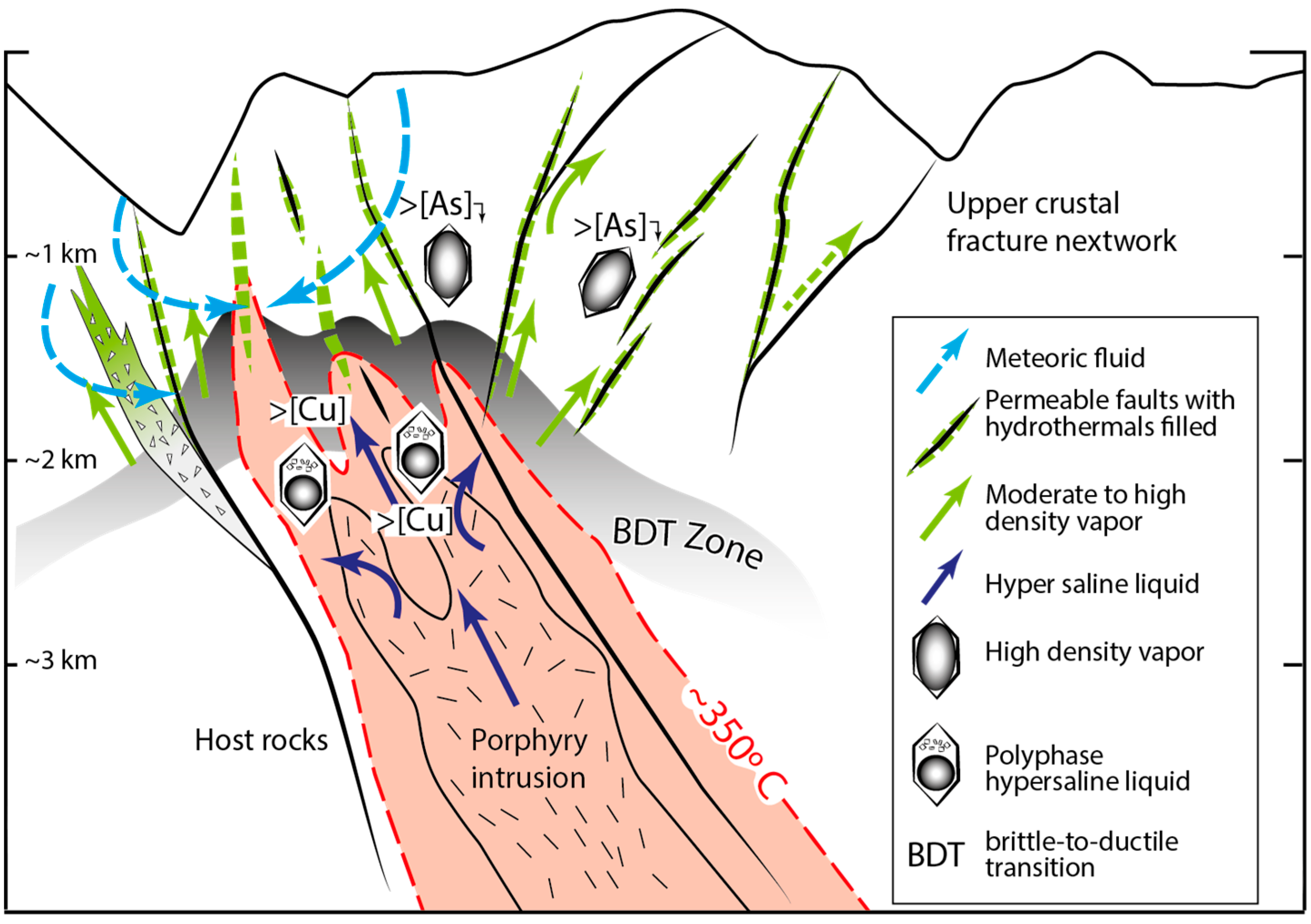
In a mining operation, the Arsenic (As) concentrations must be carefully controlled to determine the most suitable methods for mine extraction and processing as well as to establish the environmental safety conditions for tailings operation [11,13]. Beyond this operational mining condition, arsenic is an interesting element to be investigated in hydrothermal ore systems. For the case of meso- and epithermal deposits it is commonly proposed that As-rich sulfides play a role in scavenging gold [16,17,18,19]. Particularly, for porphyry systems, the geochemical behavior of arsenic has been recently investigated, showing that arsenic is geochemically decoupled from copper (Cu). In these hydrothermal systems [19,20], decoupling between copper and arsenic is due to changes in the composition of the hydrothermal fluid [20,21]. Copper and As selective geochemical partitioning [19,20,21,22] is considered the result of a fluid-phase separation process (or boiling), in which a single-phase ore-fluid is separated into a low-density vapor and denser brine phase (Figure 1). In this fluid separation, arsenic is preferentially concentrated into the low-density–low-salinity vapor phase, while copper is partitioned preferentially into the high-density saline brine fluid phase [23,24]. This fluid-phase separation takes place at the brittle-to-ductile transition (BDT) depths for porphyry systems (~1–3 km) [24,25], which is defined as the boundary-zone between the lithostatically pressured up-flow of hot magmatic fluids and the hydrostatically pressured convection of cooler meteoric fluids [25]. However, only the As-rich vapor phase is considered to be able to migrate upwards in the system through the permeable fracture network [21] developed in the upper crust (Figure 1). Interestingly, the As-rich vapor fluid phase migration can trigger fluid overpressure conditions during its ascent, resulting in fracturing in the shallowest parts of the hydrothermal system [21], and this process can be accompanied by a preferential precipitation of As-bearing minerals in the superficial fracture network (Figure 1). The copper-arsenic geochemical decoupling implies that Cu-bearing sulfides preferentially precipitate in the deeper part of the porphyry system, while As-bearing sulfides would precipitate in shallower parts, frequently filling the permeable fracture network (Figure 1), accompanied by a minor proportion of Cu-bearing sulfides [19,20,21].
3. The Case of Study: Main Mineralogical Features of the Los Bronces-Río Blanco Porphyry Cu-Mo Deposit
The “Los Bronces-Río Blanco” porphyry Cu-Mo deposit is emplaced in the Miocene to early Pliocene Andean magmatic arc and is developed in the frontal cordillera of the Central Andes of Chile in South America (Figure 2a) [12,14,15,26]. It is exploited in two neighbor mining operations (Figure 2b), namely the Los Bronces Mine, which is managed by the Anglo American Company and the Andina Mine, managed by CODELCO (Corporación Nacional de Cobre, Santiago, Chile). Recent discoveries by Anglo American have determined that this porphyry deposit is one of the largest world class metal districts [12,14,15,26]. In the Los Bronces Mine, extraction is developed at ~4000 m above mean sea level (a.m.s.l.), by excavation of an open-pit ~3 km × 2 km (long × width), and up to ~800 m deep (Figure 3a).
The main mineralization processes at the Los Bronces-Río Banco deposit (from 8.4 ± 0.5 to 4.3 ± 0.05 Ma) are associated with the important development of hydrothermal breccias, which are superimposed by a late brittle deformation stage [15,27]. Mineralization is associated with the deposition of the volcanic Farellones Formation and the emplacement of the Rio Blanco-San Francisco batholith [14,15,27]. The magmatic-hydrothermal system was developed in this region (between 16 and 4 Ma), as a result of a long-lived magmatic chamber activity, where the mass transference along the upper crust seems to have been controlled by (i) the Andean deformation regime that prepared the upper crustal structure; and (ii) the fast exhumation rates documented in the region between ~6–3 Ma [15,27].
In the metallogenic framework, three ore-forming stages have been identified: (i) an early hydrothermal stage, including the porphyry Cu-Mo deposit; (ii) a superimposed hydrothermal breccia complex, proposed as the main hydrothermal stage; and (iii) a polymetallic fault-vein (Figure 3b) emplacement phase associated to the late hydrothermal stages [14,15]. Mineralogically, the early and main mineralization stages are mostly constituted by copper (Cu) ± molybdenum (Mo)-bearing sulfides, such as: (i) essentially chalcopyrite (CuFeS2), accompanied by bornite (Cu5FeS4), molybdenite (MoS2), and pyrite (FeS2) for the early stage; and (ii) pyrite and chalcopyrite, accompanied in a minor proportion by chalcocite (Cu2S) and covellite (CuS) for the main stage case. While the As-bearing sulfides (Figure 3c,d), such as enargite (Cu3AsS4), and tennantite [(Cu,Fe)12As4S13] are only recognized in the late-stage polymetallic veins (Figure 3b), accompanied by pyrite, chalcopyrite, bornite, sphalerite [(Zn,Fe)S], galena (PbS), and primary chalcocite and covellite [29,30]. Interestingly, the main faults recognized in the Los Bronces Mine are filled by later hydrothermal mineral paragenesis (Figure 3b), especially including arsenic-bearing sulfides, i.e., tennantite and enargite (Figure 3b–d).
4. Without-Arsenic Structural Model
Considering that structural models are first-order data required for geotechnical design and mine management, at the Los Bronces Mine this goal has been developed by the Geotechnical Superintendence at the Los Bronces, Anglo American. It is based on a database with more than 200,000 single-points, including superficial and underground data (dip/dip-direction measurements) (Figure 4). The “Los Bronces structural-database” is the results of a data compilation following a systematic characterization policy, which has been generated from standard structural characterization methods, mainly including (i) slope and drill-hole cores direct mapping; (ii) indirect slopes mapping using photogrammetric technics (ShapeMetrix3D); and (iii) indirect structural mapping from geophysical measurements of boreholes (optic and acoustic tele-viewer).
The Rio Blanco-Los Bronces district is emplaced on the western flank of the Central Andes structure [28,31,32]. This structure is characterized by the development of an imbricated reverse fault system, defined as the West Andean Thrust (WAT; [32]). In this geodynamic context, the Cenozoic volcanoclastic extensional basin was inverted, accommodating the orogenic shortening responsible of the Andean uplift [32]. This basin was deformed as a fold-thrust belt, where the syntectonic plutonic emplacement was controlled by the fold axes (e.g., San Francisco Batholith; Figure 5a). At the district scale, the deformation is characterized mainly by a profuse development of a NE-striking vein-fault pattern (Figure 5b). This pattern has a hybrid kinematics evidenced by strike-slip displacement and hydrothermal filling [28,31,32]. The vein-fault pattern cuts the entire bedrock system including a folded volcanoclastic sequence of the Farellones Formation, the granitoid rocks of San Francisco Batholith, minor intrusions and the mineralized hydrothermal breccias [26,28,31] (Figure 5b). The kinematic model of the district (Figure 5c; [31]) explains the relationship between the regional and mine scale structural patterns. The first-order deformation is represented by the blind west-vergent thrusts, while the superficial deformation observed in the mine slopes and district outcrops is mainly characterized by NE-ENE-strike dextral faults and vein-faults, which are interpreted as a secondary deformation pattern developed in the shallower part of the orogenic fold-thrust belt structure [32]. Primary mineralization was controlled by NS-strike deep structures (Figure 5c) and the shallower structures are related to post-mineral deformation stages, concomitant with the later hydrothermal activity during the exhumation of the deposit.
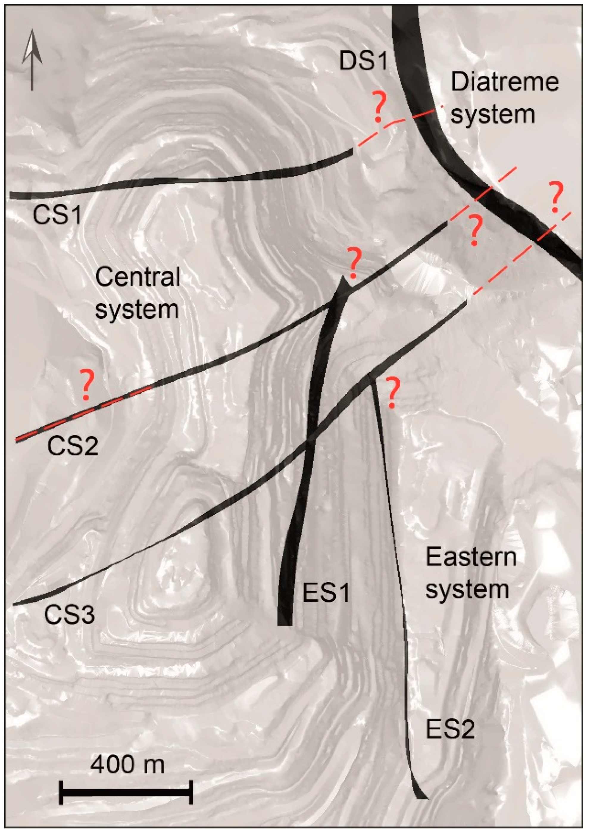
At the scale of the Los Bronces Mine (Figure 6), six single principal faults have been described in the currently-used structural model, which are associated to three main brittle deformation patterns that control the open-pit slopes. The most important structural pattern labeled as the Central System (Figure 6) and constituted by CS1, CS2, and CS3 faults, shows a NE-SW to E-W striking orientation with a high angle of dip. In addition, an N-S oriented pattern is recognized in the eastern part of the mine, labeled as the Eastern System and constituted by ES1 and ES2 faults (Figure 6). The third structural pattern, labeled as the Diatreme System, is constituted by the DS fault, which exposes a ring-type geometry and is associated with a later diatreme intrusion shear-contact (Figure 6).
Even though this model is supported by a robust structural database (Figure 4), the nature of the fault patterns does not allow the recognition of 3-D correlations from the isolated structural data. In consequence, the real persistence of structures, cross-cutting relationships, and clear fault hierarchies are poorly constrained (Figure 6), especially in the subsurface. This lack of structural attribute characterization is commonly found in mining operations and usually, it is solved using interpretations given by consultant structural geologists. However, uncertainties in the geotechnical design can be not well-controlled by this approach.
5. Arsenic Database: A Complementary Tool
The arsenic database is constituted by 648,956 analysis points from blast-hole and drill-hole samples. The 3-D spatial distribution of data shows two arrangements: (i) arsenic concentration points measured each 5 meter along the depth of geological drill-holes, which are heterogeneously distributed through the mine; and (ii) a single-point data collected from each blast-hole, which are homogeneously spaced as a block of ~7 × 7 × 15 m3 (Figure 7a).
The Arsenic concentrations range from 2 ppm (the limit of detection of the analytical technique) up to 13,000 ppm. The chemical analyses were performed by atomic absorption spectroscopy (AAS) analytical technique, following standard protocols. Although this database was originally compiled for metallurgical design and wastes control, it can be used as a complementary vector to track faults in a 3-D space, as long as these faults are sealed by As-bearing mineral fillings.
The Arsenic-database was processed using the Leapfrog Geo software (version 4.2.3, LeapFrog Enterprises Inc., Emeryville, CA, USA) [33], an implicit free-form drawing and modeling tool which allows an easy management of big-data, offering a new opportunity to integrate multi-collected data in a single and easy-handle 3-D representation. Implicit modeling is a technique that uses a radial basis function which allows for the interpolation of borehole data, outcrop data, and field structural data [34].
The Leapfrog’s output results (Figure 7a) reveal singular 3-D arsenic distributions from the interpolated data. Interestingly, the highest As-concentrations, e.g., >200 ppm, suggest tabular patterns, principally with a NE-SW orientation, which can be related to structurally controlled alignments (Figure 7a).
The orthographic projection of the spatial distribution of arsenic concentrations (Figure 7a) from drill-holes (aligned points) and blast-holes (points with a high-density distribution) denotes alignments that match the main faults (Figure 7a,b) described in the currently-used structural model of the mine (Figure 6). Remarkably, these As-rich alignments can be followed beyond extensions previously determined for the structures in the currently-used model (Figure 6), even in the subsurface, validating their recognized existence, and elucidating their real persistence across the mine as well as their cross-cutting relationships (Figure 7a,b). Additionally, the As-rich alignments also validate the real persistence of the faults down dip (Figure 7c). Even more interestingly, these As-rich alignments denote three not previously recognized principal faults, labeled as As1, As2, and As3 faults, as well as many other subordinate structures (Figure 7a,b), which can be incorporated in the improved structural model. These arsenic-located structures correspond to faults that were activated in the brittle-ductile transition zone [25]. The fault activation process allows the fluid circulation and boiling [35], triggering arsenic-bearing minerals precipitation as fault filling. Faults that were not activated at the late stages of the hydrothermal event, for example, the ES1, ES2, and DS1 faults, are not shown in the orthographic projection of the arsenic distribution.
6. Arsenic-Improved Structural Model
Using the Arsenic-database a spatial correlation has been performed between the arsenic distribution orthographic projection and the currently-used structural model (Figure 8a). The main improvements are (Figure 8b) (i) the existence of the principal faults, which were described in the currently-used structural model (Central, Eastern and Diatreme systems), has been confirmed from an independent set of data; (ii) the real persistence of the principal fault has been validated, not only along the strike but also down the dip. It can be clearly validated and highlighted for the case of the CS2 fault (Figure 6 vs. Figure 8a,b); (iii) the detailed cross-cutting relationships between the principal faults have been determined and validated; and (iv) the arsenic database has determined for the first time the existence, real persistence and hierarchy of three new principal faults, named as As1, As2, As3 (Figure 8b), corresponding to arsenic-filled fractures that had not been recognized in the former structural characterization, and therefore had not been considered in the currently-used geomechanical model. It is important to point out that there were direct structural data that indicated the existence of these newly-defined faults. Nevertheless, it was not enough to define their persistence and hierarchy through the open pit mining operation. These arsenic-located structures correspond to faults activated during the late stages of the hydrothermal event at the brittle-ductile transition zone [25]. Other structures not indicated by the arsenic data are interpreted as (i) sealed faults which were not reactivated during the late stages of the hydrothermal event, and/or (ii) faults reactivated or propagated after the hydrothermal event.
7. Discussion and Concluding Remarks
The development of the proposed tool is based on the tectonic and metallogenic conceptual framework that explains the spatial correlation between ore-fluid circulation and mineral precipitation in fractures developed as a network in the upper continental crust. In this study, it has been shown that the tridimensional distribution of arsenic concentrations can be used to confirm the existence and the real persistence of structures as well as the cross-cutting relationships between faults. This characterization of faults has a direct impact on the robustness of the total slope and inter-ramp geotechnical design as well as the slope stability analysis [3,4,5,7]. The implementation of the proposed tool also allows for the representation of other subordinated structural patterns, at a scale from inter-ramp to slope; which can show evidence of fault characteristics such as kinematics and the magnitude of displacement.
Our results show that linking the direct discontinuities characterization to the implementation of geochemically-developed tools can improve the quality of the structural models at a mine scale, allowing the development of more realistic representations of the rock-mass scenarios, which can minimize uncertainties in the geotechnical modelling.
Finally, the proposed tool can be also comprehensively developed using other chemical elements, which can be systematically quantified in a mining operation. In a similar way, it can be implemented in other hydrothermal systems, including meso- and epi-thermal deposits, in which the fractures are sealed by hydrothermal ore paragenesis containing As-bearing minerals. Significantly, the use of a geochemical database to improve structural models represents an outstanding opportunity to enhance the investment made to quantify concentrations of chemical elements, other than the economically profitable metal, in mined rock-mass. In any case, it is necessary to make clear that the proposed methodology is not intended to replace the classical direct mapping of structures, which is a fundamental input to develop structural models in mining.
Author Contributions
D.C. and C.B. conceived the main idea; D.C., C.B. and G.V. analyzed the data and proposed the tool; D.C., G.V. and C.B. wrote the paper; Conceptualization, D.C. and C.B.; Investigation, G.V.; Resources, C.B.; Writing-review & editing, D.C., C.B. and G.V.
Funding
This research received no external funding.
Acknowledgments
We wish to thank Anglo American T&S, particularly to M. Schellman (Principal Geomechanics) and P. Hodkiewicz (Head of Specialist and Integrated Geosciences), for allowing the preparation of this paper. We would also like to thank I. Vela (Geology Superintendent of the Los Bronces Underground) for his constructive discussions made on the manuscript. Thanks to LeapFrog Geo for supporting this research through a data analysis and modeling software endowment.
Conflicts of Interest
The authors declare no conflict of interest.
References
- Bond, C.E. Uncertainty in structural interpretation: Lessons to be learnt. J. Struct. Geol. 2015, 74, 185–200. [Google Scholar] [CrossRef] [Green Version]
- Paradella, W.R.; Ferretti, A.; Mura, J.C.; Colombo, D.; Gama, F.F.; Tamburini, A.; Santos, A.R.; Novali, F.; Galo, M.; Camargo, P.O.; et al. Mapping surface deformation in open pit iron mines of Carajás Province (Amazon Region) using an integrated SAR analysis. Eng. Geol. 2015, 193, 61–78. [Google Scholar] [CrossRef]
- Stead, D.; Wolter, A. A critical review of rock slope failure mechanisms: The importance of structural geology. J. Struct. Geol. 2015, 74, 1–23. [Google Scholar] [CrossRef]
- Morales, M.; Panthi, K.K.; Botsialas, K.; Holmøy, K.H. Development of a 3D structural model of a mine by consolidating different data sources. Bull. Eng. Geol. Environ. 2017, 1–19. [Google Scholar] [CrossRef]
- Shang, J.; West, L.J.; Hencher, S.R.; Zhao, Z. Geological discontinuity persistence: Implications and quantification. Eng. Geol. 2018, 241, 41–54. [Google Scholar] [CrossRef]
- Vatcher, J.; Mckinnon, S.D.; Sjöberg, J. Developing 3-D mine-scale geomechanical models in complex geological environments, as applied to the Kiirunavaara Mine. Eng. Geol. 2016, 203, 140–150. [Google Scholar] [CrossRef]
- Carlà, T.; Farina, P.; Intrieri, E.; Botsialas, K.; Casagli, N. On the monitoring and early-warning of brittle slope failures in hard rock masses: Examples from an open-pit mine. Eng. Geol. 2017, 228, 71–81. [Google Scholar] [CrossRef]
- Bakhtavar, E.; Shahriar, K.; Oraee, K. Transition from open-pit to underground as a new optimization challenge in mining engineering. J. Min. Sci. 2009, 45, 485–494. [Google Scholar] [CrossRef]
- MacNeil, J.A.L.; Dimitrakopoulos, R.G. A stochastic optimization formulation for the transition from open pit to underground mining. Optim. Eng. 2017, 18, 793–813. [Google Scholar] [CrossRef] [Green Version]
- Willenberg, H.; Loew, S.; Eberhardt, E.; Evans, K.F.; Spillmann, T.; Heincke, B.; Maurer, H.; Green, A.G. Internal structure and deformation of an unstable crystalline rock mass above Randa (Switzerland): Part I—Internal structure from integrated geological and geophysical investigations. Eng. Geol. 2008, 101, 1–14. [Google Scholar] [CrossRef]
- Schwartz, M.O. Arsenic in Porphyry Copper Deposits: Economic Geology of a Polluting Element. Int. Geol. Rev. 1995, 37, 9–25. [Google Scholar] [CrossRef]
- Sillitoe, R.H. Porphyry Copper Systems. Econ. Geol. 2010, 105, 3–41. [Google Scholar] [CrossRef]
- Nazari, A.M.; Radzinski, R.; Ghahreman, A. Review of arsenic metallurgy: Treatment of arsenical minerals and the immobilization of arsenic. Hydrometallurgy 2017, 174, 258–281. [Google Scholar] [CrossRef]
- Irarrazaval, V.; Sillitoe, R.H.; Wilson, A.J.; Toro, J.C.; Robles, W.; Lyall, G. Discovery History of a Giant, High-Grade, Hypogene Porphyry Copper-Molybdenum Deposit at Los Sulfatos, Los Bronces-Río Blanco District, Central Chile. In The Challenge of Finding New Mineral Resources: Global Metallogeny, Innovative Exploration, and New Discoveries; Goldfarb, R.J., Marsh, E.E., Monecke, T., Eds.; Special Publications of the Society of Economic Geologists: Littleton, CO, USA, 2010; pp. 253–269. [Google Scholar]
- Toro, J.C.; Ortúzar, J.; Zamorano, J.; Cuadra, P.; Hermosilla, J.; Spröhnle, C. Protracted magmatic-hydrothermal history of the Río Blanco-Los Bronces district, Central Chile: Development of world’s greatest known concentration of copper. In Geology and Genesis of Major Copper Deposits and Districts of the World: A Tribute to Richard H. Sillitoe; Hedenquist, J.W., Harris, M., Camus, F., Eds.; Special Publications of the Society of Economic Geologists: Littleton, CO, USA, 2012; pp. 105–126. [Google Scholar]
- Fleet, M.E.; Mumin, A.H. Gold-bearing arsenian pyrite and marcasite and arsenopyrite from Carlin Trend gold deposits and laboratory synthesis. Am. Miner. 1997, 82, 182–193. [Google Scholar] [CrossRef]
- Simon, G.; Huang, H.; Penner-Hahn, J.E.; Kesler, S.E.; Kao, L.S. Oxidation state of gold and arsenic in gold-bearing arsenian pyrite. Am. Miner. 1999, 84, 1071–1079. [Google Scholar] [CrossRef]
- Reich, M.; Kesler, S.E.; Utsunomiya, S.; Palenik, C.S.; Chryssoulis, S.L.; Ewing, R.C. Solubility of gold in arsenian pyrite. Geochim. Cosmochim. Acta 2005, 69, 2781–2796. [Google Scholar] [CrossRef]
- Deditius, A.P.; Reich, M.; Kesler, S.E.; Utsunomiya, S.; Chryssoulis, S.L.; Walshe, J.; Ewing, R.C. The coupled geochemistry of Au and As in pyrite from hydrothermal ore deposits. Geochim. Cosmochim. Acta 2014, 140, 644–670. [Google Scholar] [CrossRef] [Green Version]
- Reich, M.; Deditius, A.; Chryssoulis, S.; Li, J.W.; Ma, C.Q.; Parada, M.A.; Barra, F.; Mittermayr, F. Pyrite as a record of hydrothermal fluid evolution in a porphyry copper system: A SIMS/EMPA trace element study. Geochim. Cosmochim. Acta 2013, 104, 42–62. [Google Scholar] [CrossRef]
- Tardani, D.; Reich, M.; Deditius, A.P.; Chryssoulis, S.; Sánchez-Alfaro, P.; Wrage, J.; Roberts, M.P. Copper–arsenic decoupling in an active geothermal system: A link between pyrite and fluid composition. Geochim. Cosmochim. Acta 2017, 204, 179–204. [Google Scholar] [CrossRef] [Green Version]
- Franchini, M.; McFarlane, C.; Maydagán, L.; Reich, M.; Lentz, D.R.; Meinert, L.; Bouhier, V. Trace metals in pyrite and marcasite from the Agua Rica porphyry-high sulfidation epithermal deposit, Catamarca, Argentina: Textural features and metal zoning at the porphyry to epithermal transition. Ore Geol. Rev. 2015, 66, 366–387. [Google Scholar] [CrossRef]
- Kouzmanov, K.; Pokrovski, G.S. Hydrothermal Controls on Metal Distribution in Porphyry Cu (-Mo-Au) Systems. In Geology and Genesis of Major Copper Deposits and Districts of the World: A Tribute to Richard H. Sillitoe; Hedenquist, J.W., Harris, M., Camus, F., Eds.; Special Publications of the Society of Economic Geologists: Littleton, CO, USA, 2012; pp. 573–618. [Google Scholar]
- Pokrovski, G.S.; Borisova, A.Y.; Bychkov, A.Y. Speciation and Transport of Metals and Metalloids in Geological Vapors. Rev. Mineral. Geochem. 2013, 76, 165–218. [Google Scholar] [CrossRef] [Green Version]
- Weis, P.; Driesner, T.; Heinrich, C.A. Porphyry-Copper Ore Shells Form at Stable Pressure-Temperature Fronts within Dynamic Fluid Plumes. Science 2012, 338, 1613–1616. [Google Scholar] [CrossRef] [PubMed]
- Piquer, J.; Skarmeta, J.; Cooke, D.R. Structural evolution of the Rio Blanco-Los Bronces District, Andes of Central Chile: Controls on stratigraphy, magmatism, and mineralization. Econ. Geol. 2015, 110, 1995–2023. [Google Scholar] [CrossRef]
- Deckart, K.; Silva, W.; Spröhnle, C.; Vela, I. Timing and duration of hydrothermal activity at the Los Bronces porphyry cluster: An update. Miner. Depos. 2014, 49, 535–546. [Google Scholar] [CrossRef]
- Carrizo, D.; Barros, C. El Modelo Estructural del Depósito Los Bronces, Andes Centrales, Chile; Internal Report; Anglo American Chile S.A., División Los Bronces: Santiago, Chile, 2017; p. 52. (In Spanish) [Google Scholar]
- Grez, E.; Spröhnle, C. Los Bronces Porphyry Copper Target; Internal Report; Anglo American Chile, División Los Bronces, Gerencia de Exploraciones, Exploraciones Categoría III: Santiago, Chile, 2003. (In Spanish) [Google Scholar]
- Barros, C. Distribución y Modelamiento Preliminar del Arsénico, Bismuto, Plomo, Antimonio, Zinc, Plata y oro en la Mineralización Profunda de la Mina Los Bronces, Región Metropolitana, Chile. Undergraduate Thesis, Universidad Católica del Norte, Antofagasta, Chile, 2007; p. 141. (In Spanish). [Google Scholar]
- Carrizo, D. Estudio Estructural en Torno al Socavón Sur, Los Sulfatos: Proyecto Los Bronces Underground–LBUG; Internal Report; Anglo American Chile S.A., División Los Bronces: Santiago, Chile, 2017; p. 35. (In Spanish) [Google Scholar]
- Riesner, M.; Lacassin, R.; Simoes, M.; Carrizo, D.; Armijo, R. Revisiting the Crustal Structure and Kinematics of the Central Andes at 33.5°S: Implications for the Mechanics of Andean Mountain Building. Tectonics 2018, 37, 1347–1375. [Google Scholar] [CrossRef]
- Cowan, E.J.; Lane, R.G.; Ross, H.J. Leapfrog’s implicit drawing tool: A new way of drawing geological objects of any shape rapidly in 3D. In Proceedings of the Australian Institute of Geoscientists Mining Geology 2004 Workshop, Brisbane, Australia, 21 October 2004; pp. 23–25. [Google Scholar]
- Birch, C. New systems for geological modelling-black box or best practice? J. S. Afr. Inst. Min. Metall. 2014, 114, 993–1000. [Google Scholar]
- Cox, S.F. Faulting processes at high fluid pressures: An example of fault valve behavior from the Wattle Gully Fault, Victoria, Australia. J. Geophys. Res. 1995, 100, 12841–12859. [Google Scholar] [CrossRef]
Figure 1.
The conceptual schema of an idealized porphyry Cu-Mo deposit showing the ore-fluid phase separation and the As-Cu geochemical partitioning (simplified from Reference [23]). The brittle-to-ductile transition (BDT) zone is simplified from Reference [25].

Figure 2.
(a) The simplified tectonic map of South America showing the regional location of the Los Bronces-Rio Blanco District in relation to the metallogenic provinces of the Central Andes. (b) Leapfrog’s orthographic projection of the Rio Blanco-Los Bronces district, showing the location of the Los Bronces Mine and the Andina Mine (modified from Reference [28]).

Figure 3.
(a) Photograph of the Los Bronces open pit. (b) Photograph of an outcrop showing a principal fault-vein filled by the As-bearing minerals. Scanning electron microscopy (SEM)-backscattered electron (BSE) images of an enargite (c) and a tennantite (d) crystal.
Figure 3.
(a) Photograph of the Los Bronces open pit. (b) Photograph of an outcrop showing a principal fault-vein filled by the As-bearing minerals. Scanning electron microscopy (SEM)-backscattered electron (BSE) images of an enargite (c) and a tennantite (d) crystal.

Figure 4.
The 3-D schematic representation of the structural database acquired for the Los Bronces mine. Green dots show slope mapping data and magenta dots indicate drill-hole mapping information.
Figure 4.
The 3-D schematic representation of the structural database acquired for the Los Bronces mine. Green dots show slope mapping data and magenta dots indicate drill-hole mapping information.

Figure 5.
(a) A simplified east-west structural cross sections showing the tectonic context of the Rio Blanco-Los Bronces mining district (after Reference [32]). WAT: Western Andean Thrust, Pz: Paleozoic, Mz: Mesozoic, Cz: Cenozoic; (b) A simplified geological map of the Rio Blanco-Los Bronces district showing the main structural patterns and the mine-scale strain tensor (after Reference [28]); (c) Kinematic model showing the relationship between the different-scale structural patterns observed in the mining district. The model explains the kinematic relevance of the different structures under the plate convergence vector (after Reference [32]).

Figure 6.
The schematic representation of the structural model currently used, showing the recognized principal faults. The main issues on the model are pointed out by question marks. CS: Central System Faults 1, 2 and 3; ES: Eastern System Faults 1 and 2; DS: Diatreme System Fault.
Figure 6.
The schematic representation of the structural model currently used, showing the recognized principal faults. The main issues on the model are pointed out by question marks. CS: Central System Faults 1, 2 and 3; ES: Eastern System Faults 1 and 2; DS: Diatreme System Fault.

Figure 7.
(a) Orthographic projection of the spatial distribution of arsenic concentrations from drill-holes (aligned points) and blast-holes (points with a high-density distribution). (b) Sketch of orthographic projection showed in (a), outlining the previously recognized main faults, three arsenic-denoted new principal faults (labeled as As1, As2, and As3 faults) and some arsenic-denoted subordinated faults. (c) A NNW-SSE cross-section showing the geometry of arsenic concentrations in depth. The inset in (c) outlines previously recognized and arsenic-denoted main faults. CS: Central System Faults 1, 2 and 3.

Figure 8.
The Arsenic-improved structural model. (a) Spatial correlation between the As-database orthographic projection and the currently-used structural model. (b) Main progress in the structural model, including the three newly-revealed principal faults as well as the real persistence and cross-cutting fault relationships.

© 2018 by the authors. Licensee MDPI, Basel, Switzerland. This article is an open access article distributed under the terms and conditions of the Creative Commons Attribution (CC BY) license (http://creativecommons.org/licenses/by/4.0/).
Share and Cite
MDPI and ACS Style
Carrizo, D.; Barros, C.; Velasquez, G. The Arsenic Fault-Pathfinder: A Complementary Tool to Improve Structural Models in Mining. Minerals 2018, 8, 364. https://doi.org/10.3390/min8090364
AMA Style
Carrizo D, Barros C, Velasquez G. The Arsenic Fault-Pathfinder: A Complementary Tool to Improve Structural Models in Mining. Minerals. 2018; 8(9):364. https://doi.org/10.3390/min8090364
Chicago/Turabian StyleCarrizo, Daniel, Carlos Barros, and German Velasquez. 2018. "The Arsenic Fault-Pathfinder: A Complementary Tool to Improve Structural Models in Mining" Minerals 8, no. 9: 364. https://doi.org/10.3390/min8090364
Note that from the first issue of 2016, this journal uses article numbers instead of page numbers. See further details here.