Article

Undifferentiated Inorganics in Coal Fly Ash and Bottom Ash: Calcispheres, Magnesiacalcispheres, and Magnesiaspheres

by
Bruno Valentim
1,*,
Barbara Białecka
2,
Paula Alexandra Gonçalves
1,
Alexandra Guedes
1,
Renato Guimarães
1,
Mihai Cruceru
3,
Joanna Całus-Moszko
2,
Luminiţa Georgeta Popescu
3,
Georgeta Predeanu
4 and
Ana Cláudia Santos
1
1
Instituto de Ciências da Terra (ICT), Pólo do Porto, Faculdade de Ciências da Universidade do Porto (FCUP), Rua do Campo Alegre, 4169-007 Porto, Portugal
2
Główny Instytut Górnictwa, Central Mining Institute (GIG), plac Gwarków 1, 40-166 Katowice, Poland
3
Department of Automation, Energy, Environment and Sustainable Development, Faculty of Engineering, “Constantin Brâncuşi” University of Târgu-Jiu, Eroilor 30, 210152 Târgu Jiu, Romania
4
University Politehnica of Bucharest, Research Center for Environmental Protection and Eco-Friendly Technologies (CPMTE), Polizu 1, Sector 1, 011061 Bucharest, Romania
*
Author to whom correspondence should be addressed.
Minerals 2018, 8(4), 140; https://doi.org/10.3390/min8040140
Submission received: 22 February 2018 / Revised: 23 March 2018 / Accepted: 26 March 2018 / Published: 2 April 2018
(This article belongs to the Special Issue Toxic Mineral Matter in Coal and Coal Combustion Products)

Abstract

:
During a study aiming to recover strategic elements and minerals from coal fly ash and bottom ash (RAREASH and CHARPHITE projects funded, respectively, by the 2nd ERA-MIN and 3rd ERA-MIN Programs of the European Union Commission), it was found that in coal fly ash and bottom ash from Romania and Poland, several morphotypes did not fit into the general fly ash classifications, unless grouped together as “undifferentiated inorganics”. However, the combination of reflected light optical microscopy under oil immersion, scanning electron microscopy, and X-ray microanalysis (SEM/EDS) showed that many of these morphotypes not only have distinctive petrographic patterns but are also characterized by a chemical assemblage dominated by Ca, Mg, and P. In this paper, a survey of the literature is presented together with several detailed studies of samples from the RAREASH and CHARPHITE projects from which the following nomenclature are proposed: “calcispheres” for spongy Ca-rich morphotypes, “calcimagnesiaspheres” for (Ca + Mg)-rich morphotypes with visible MgO nodules and/or periclase (MgO) exsolved from Ca aluminate-silicate glass, and “magnesiaspheres” divided into “magnesiaferrospheres” for (Mg + Fe)-rich morphotypes with magnesioferrite, and “magnesiaoxyspheres” for magnesiaspheres mainly composed of (Mg + Fe)-rich amorphous material with visible MgO nodules and/or periclase.

1. Introduction

Coal fly ash (FA) is a heterogeneous material because of the parent coal and coal combustion conditions’ characteristics. The most common morphotypes composing fly ashes include aluminosilicate glass (spheres or irregular), partially baked clay, ferrospheres (Fe-rich), mineral relics (e.g., quartz), and char (carbonaceous solid residue) [1,2,3,4,5]. However, the headings “undifferentiated inorganics” or “others” are commonly used by petrographers to account for scarce and diverse morphotypes occurring in low amounts (usually <1 vol %), which include mineral relics whose identification is not clear and newly formed morphotypes not included in a specific class or described in the literature.
Such diversity is due to coal heterogeneity, which influences the glass amount and its composition due to variations in the amount and chemistry of clay minerals [6,7]. The elements Na, K, Ca, Al, Mg, and Fe may be present in relatively high concentrations in coal, especially in lower rank coals, since calcite (CaCO3), pyrite (FeS2), illite (K,H3O)(Al,Mg,Fe)2(Si,Al)4O10[(OH)2,(H2O)], smectite (Na0.33(Al1.67Mg0.33)Si4O10(OH)2), and kaolinite (Al2Si2O5(OH)4) are common coal minerals, together with many other less common minerals that also have these elements in their composition. In addition, these elements, and in some cases Ti, are also present, generally as non-mineral inorganics, in low-rank coals [8,9,10,11,12]. During coal combustion, clays melt at a lower temperature due to these elements, and upon cooling they form aluminosilicate glass (Al2O3·2SiO2), with crypto-crystals of mullite and cristobalite. Na, K, Ca, and Fe in the silicate glass structure function as network modifiers since they act as a “flux agent” due to their high ionic radius, ionic distance in oxides, and field strength. However, elements like Mg and Al are intermediates that may be part of the network or modify the network, but cannot form a glass of their own like Si (SiO4), B (B2O3), and P (P2O5), which are network-formers (e.g., P2O5 cannot be mixed and form a glass with SiO4 and/or B2O3) [13,14,15,16,17,18,19].
However, other minerals may also contribute to the glass composition: additional Ca, Mg, Fe, Na, and K may be added to the SiO2–Al2O3 from carbonate decomposition, Fe sulfide oxidation, chloride volatilization, and so on [17,19]. In turn, variations in the glass composition influence the morphology of the FA and bottom ash (BA) particles since the presence of gas-producing minerals, the melting temperature of the mixed minerals, the reaction timing, and the viscosity of the melting will determine the shape and internal structure of the particles, i.e., the roundness, vacuolization, and distribution of the different phases [17,20].
Therefore, while the main FA and BA morphotypes, such as char, aluminosilicate glassy spheres, and ferrospheres, are easily recognized in general terms [2,3,5,21,22], an array of other inorganic morphotypes is ignored because they are usually present in residual volumes, and because the oil immersion reflected light microscopy is not appropriate for a detailed inorganic analysis. For example, the qualifier “undifferentiated inorganics” was removed from the round robins of the Fly-Ash Working Group, Commission III of the International Committee for Coal and Organic Petrography (ICCP), due to a high degree of disagreement related to a major lack of information concerning petrographic details [23].
The utilization of an SEM-backscattered electron mode (BSE), however, highlights many morphotypes that are “weird and unique of their kind” from a grey aluminosilicate background due to their average atomic composition, which makes it easier to characterize them, including their chemical composition by EDS (e.g., Ca-rich sphere in Dai et al. [24]; vide figure 5 in [24]). Using these methods, O’Connor, and O’Connor and Meeker [25,26,27] described the abundant occurrence of P, and of Mg–Ca, morphotypes in Wyodak–Anderson coal FA, while Valentim et al. [28] classified P-rich morphotypes in a specific class due to their distinctive petrographic characteristics, and due to the occurrence of a major or secondary P-peak in the EDS spectra.
In this work, we attempt a systematization in order to provide a nomenclature to several undifferentiated inorganic morphotypes, and in order to systematize them within the FA petrographic classification. For this purpose, the characterization of the morphotypes was made by combining scanning electron microscopy with X-ray microanalysis (SEM/EDS) to obtain topographic (secondary electron detector mode—SE) and internal structure (backscattered electron detector mode—BSE) information on the selected morphotypes with a semiquantitative chemical analysis; electron backscattered diffraction (EBSD), which is a SEM/EDS tool, was used to access precise mineralogy information in combination with the EDS information. These results were then used to help the oil immersion reflected light microscopy identification and characterization of the morphotypes.

2. Materials and Methods

The samples studied are part of a set of samples from the RAREASH and CHARPHITE projects (2nd ERA-MIN Joint Call 2014 and 3rd ERA-MIN Joint Call 2015, respectively), and include fly ash and bottom ash samples of pulverized fuel power plants (1500 °C) from Romania and Poland.
The main oxide and mineralogy composition of the samples is shown in Table 1 and Table 2, respectively.
To be universally accepted, the nomenclature and systematization of “undifferentiated inorganics” in FA and BA must rely on a combination of techniques that provide reliable objective information. In that sense, electron microprobe analysis (EMPA) provides accurate mineralogy of the materials and how they are distributed in the morphotype (e.g., [27]). However, the combination of SEM/EDS with reflected light optical microscopy analysis is more commonly used in FA and BA characterization. When adding EBDS, the combination technique approaches EMPA in terms of mineralogical information.
Regarding the petrographic analysis (Poil), the samples were prepared according to standard procedures [29]. The samples were analyzed at ICT (Portugal) using a Leica DM4000 microscope equipped with a Discus-Fossil system using ×50 and ×100 oil immersion objectives in non-polarized and polarized reflect white light. In some petrographic images, a retarder plate of 1λ was also used together with the polarized reflected light.
SEM/EDS/EBSD: SEM was used to characterize the topography and sections of the ash morphotypes, the semi-quantitative determination of their chemical composition, and to carry out an EBSD analysis for the microstructural-crystallographic characterization of a section of a magnesiasphere, which was combined with the EDS technique for phase discrimination.

3. Nomenclature and Systematization
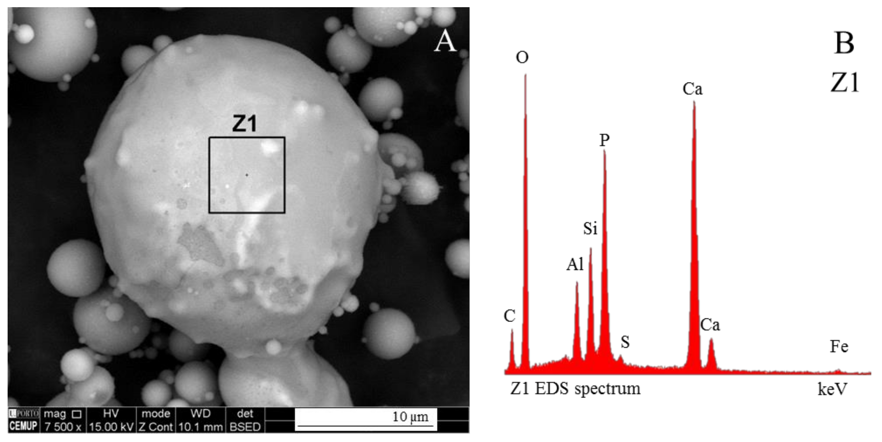
The SEM/EDS BSE mode of pulverized fuel FA and BA samples from Romania and Poland shows residual volumes of sub-rounded to rounded morphotypes with a brightness between the aluminosilicate glass and the ferrospheres, and primarily with P, Ca, and Mg EDS peaks. While P-bearing morphotypes (Figure 1A,B) were named “phosphospheres” by Valentim et al. [28] since P is capable of forming a network of its own and forming a morphotype with a distinctive “pomegranate” structure composed of P-bearing microglobules in the Al–Si matrix [27,28], no petrographic nomenclature exists for Ca and Mg morphotypes. They may be included in a category together with “others” or they may be named “undifferentiated inorganics”; consequently, they will not be differentiated. If they occur in large amounts, the petrographer may create his own Ca and Mg category. However, these morphotypes generally occur in residual amounts, and were largely ignored despite being the only evidence, in many cases, of the presence of minerals and glasses not detected by X-ray diffraction (XRD), e.g., of Ca-rich spheres [24].
A nomenclature for Ca and Mg morphotypes is proposed based on the “distinctive element” (or “elements”), i.e., an element generating the morphotype “distinctive pattern”. For example, the “distinctive element” of ferrospheres is Fe because this element generates dendritic magnetite, which is a “distinctive pattern” of ferrospheres. In the actual FA and bottom nomenclature the “distinctive element” for “char” is carbon, for “ferrospheres” is Fe, for “aluminosilicate spheres” is Al–Si, and for “phosphospheres” is P. Therefore, for Ca the morphotypes should be called “calcispheres,” and for Mg they should be called “magnesiaspheres”.
However, a vast array of chemical associations and morphologic and structural variations are the rule due to the multi-element composition of coal minerals, and the FA and BA petrography should be, when possible, preceded by SEM/EDS to disambiguate the “distinctive element”. For example, in the large sphere shown in Figure 2 the intensity of the Ca and Mg EDS peaks is very high (Figure 2B: Z2 and Figure 2D: Z4). However, these are not the “distinctive elements” because visible dendritic magnetite and high brightness are the “distinctive patterns” of this morphotype. Fe is the “distinctive element” despite not being the dominant element in the EDS spectra. Undoubtedly the morphotype is a “ferrosphere”.
In the same micrograph, a small “phosphosphere” does not show visible dendritic magnetite or any other distinctive pattern that could help disambiguate its nomenclature. However, the EDS spectrum (Figure 2A,C: Z3) is composed of a high-intensity Ca peak, together with P and Mg medium-intensity peaks, and a low-intensity Fe peak. In this case P is the “distinctive element” since P is capable of creating its own network, as well as “distinct patterns” (generally an internal “pomegranate” texture not visible in the micrograph) [28].

3.1. Calcispheres

The Ca in coal FA and BA has its origin in calcium-bearing minerals, which are very common in coal. Ca is typically found in smectite, calcite, dolomite, or talc, which in turn will originate ashes with variable CaO concentrations (low calcium, <10%; intermediate calcium, 10%–20%; and high calcium, 20+%) and mineralogical compositions [18,30].
During coal combustion the Ca-rich clays lose water and melt, forming crystalline phases and Ca aluminate glass, while the carbonates decompose, release CO2, and form CaO and MgO. Variable amounts of Al, Si, Ca, Mg, and P are responsible for different associations of dense Ca aluminate glass, cryptocrystalline Ca aluminate (CaO·Al2O3 and 3CaO·Al2O3) admixed with glass, and crystalline phases, such as spongy Ca-bearing aluminosilicate (e.g., gehlenite (Ca2Al(Al,Si)O7)) with CaO nodules, Ca-bearing silicate (e.g., wollastonite (CaSiO3), tricalcium aluminate (3CaO·Al2O3), melilite ((Ca,Na)2(Al,Mg,Fe)(Si,Al)2O7), portlandite (Ca(OH)2), merwinite (Ca3Mg(SiO4)2), periclase (MgO), and magnesioferrite (Mg(Fe3+)2O4) [20,24,27,30,31,32].
When FA has a medium or high Ca concentration, Ca-rich spheres are a common morphotype, e.g., in Wyodak–Anderson coal FA [27]. However, when the Ca concentration is low, Ca-rich morphotypes are residual (e.g., Dai et al. [24]; vide figure 5 in [24]). Valentim et al. [28] described Ca-rich morphotypes, under the SEM BSE mode, as having a spherical to ellipsoid shape and of being made of an internal spongy texture, naming them calcispheres. This spongy texture (Figure 3) is caused by calcium reactions (e.g., the decomposition of Ca minerals and mass loss [33], and processes of exsolvation of MgO [27]), and also by the formation of Al–Si–Ca nodules (Figure 3C–F).
Not all calcispheres show a Ca spongy texture and a white color under the SEM BSE mode; some calcispheres are mostly composed of Al–Si–Ca glass and are structureless, which makes their identification even more difficult. Under Poil they are light-brown morphotypes that may show a bright yellow rim (Figure 4A–C), and where Ca is more concentrated they present a golden-yellow sugar texture (Figure 4D). This “sugar” texture is the Poil counterpart to the SEM “spongy” texture.

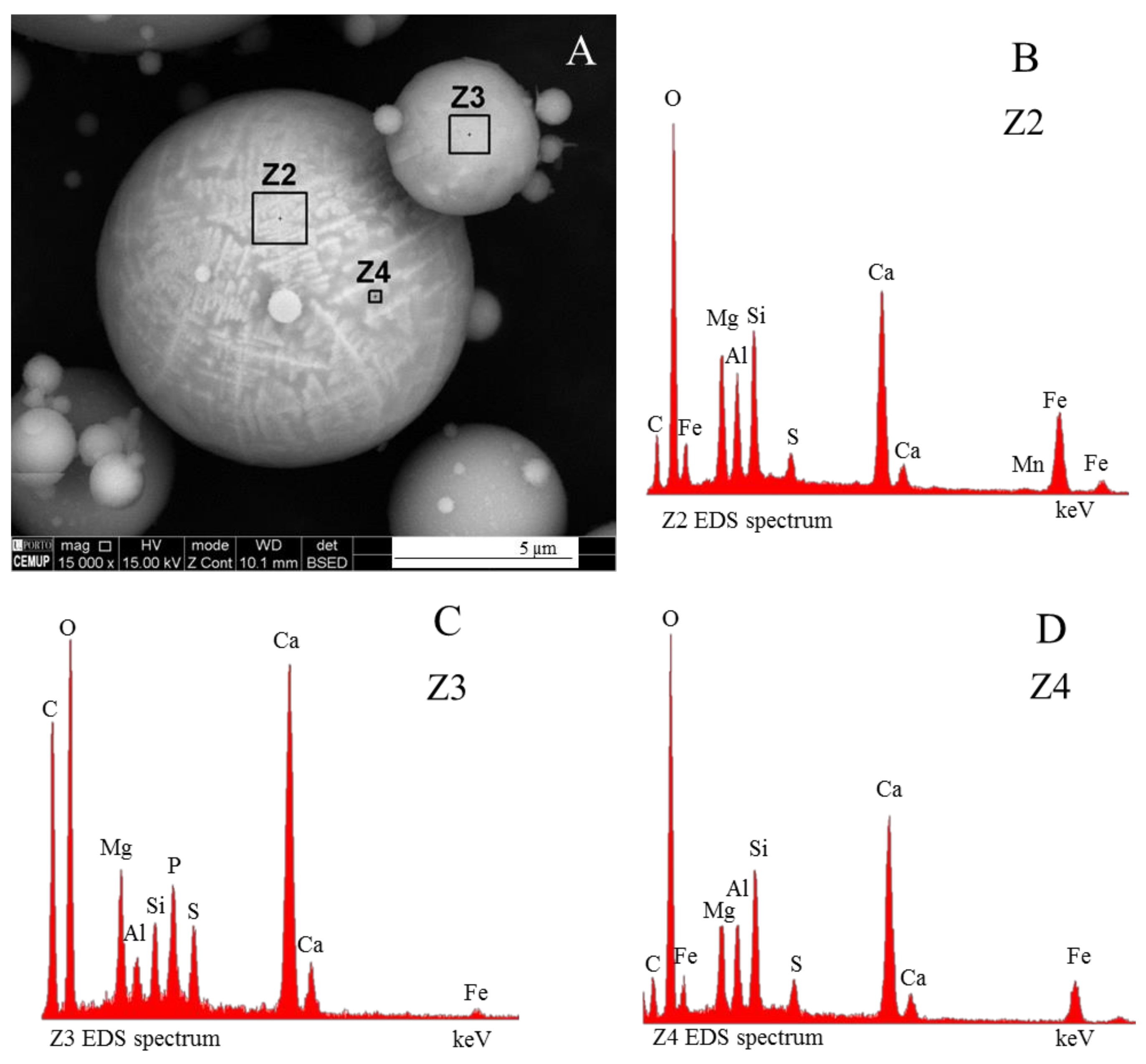
3.2. Calcimagnesiaspheres

O’Connor, O’Connor and Meeker, and Brownfield et al. [25,26,27,34,35] described in detail the (Ca + Mg) morphotypes occurring in the FA of Wyodak–Anderson coal (Powder River Basin, WY, USA). However, no nomenclature was proposed to include these morphotypes in the internationally recognized coal fly ash classifications [2,3,5,21,22]. Based on the Al and Si amounts, these authors considered three types of FA mineral assemblages; Types 1 and 2 seem relevant to this study, while Type 3 is related to phosphospheres:
Type 1, (Ca ± Mg) + Al silica-poor FA mineral assemblages commonly contain euhedral octagons or cubes of periclase and possibly minor melilite ((Ca,Na)2(Al,Mg)(Si,Al)2O7), which are crystallized in a spongy or massive glass matrix of Ca aluminate, gehlenite (Ca2Al(Al,Si)O7), or mayenite (Ca12Al14O33). The morphotypes observed consist of: (i) a matrix of Ca aluminate with exsolved euhedral octagons or cubes of periclase, euhedral to rounded subhedral crystals of lime, and small subhedral crystals of Ca–Mg–aluminate; and (ii) fly ash grains with melilite and larnite (β-Ca2SiO4) in Ca3Al2O6 glass.
Type 2 are (Ca ± Mg) + Si (moderate aluminum (Al) content) assemblages. The morphotypes observed consist of euhedral crystals of periclase and merwinite (Ca3Mg(SiO4)2) exsolved from Ca aluminate-silicate glass.
However, when the system also includes relevant amounts of Ca, a vast array of Ca-rich variations may be formed, i.e., with more or less amorphous Ca-aluminate and Ca-silicate, MgO nodules, Al–Si–Ca–(Mg–Fe), and residual magnesioferrite crystals (e.g., Figure 3E,F). These are the result of variations in the original elements’ concentration and in the intensity of the exsolvation process. One of these calcisphere subtypes consists, under SEM BSE, of bright morphotypes with an irregular or smooth topography punctuated by MgO nodules and/or euhedral periclase, and an EDS spectrum with high intensity Ca and Mg peaks and low intensity Fe, Al, and Si peaks (Figure 5). A cross section may show a Ca spongy texture, as well as MgO. Since two “distinctive patterns” (a Ca-spongy texture, along with MgO nodules or periclase) occur in the same morphotype, this morphotype may be considered an Mg-calcisphere and named a “calcimagnesiasphere”.

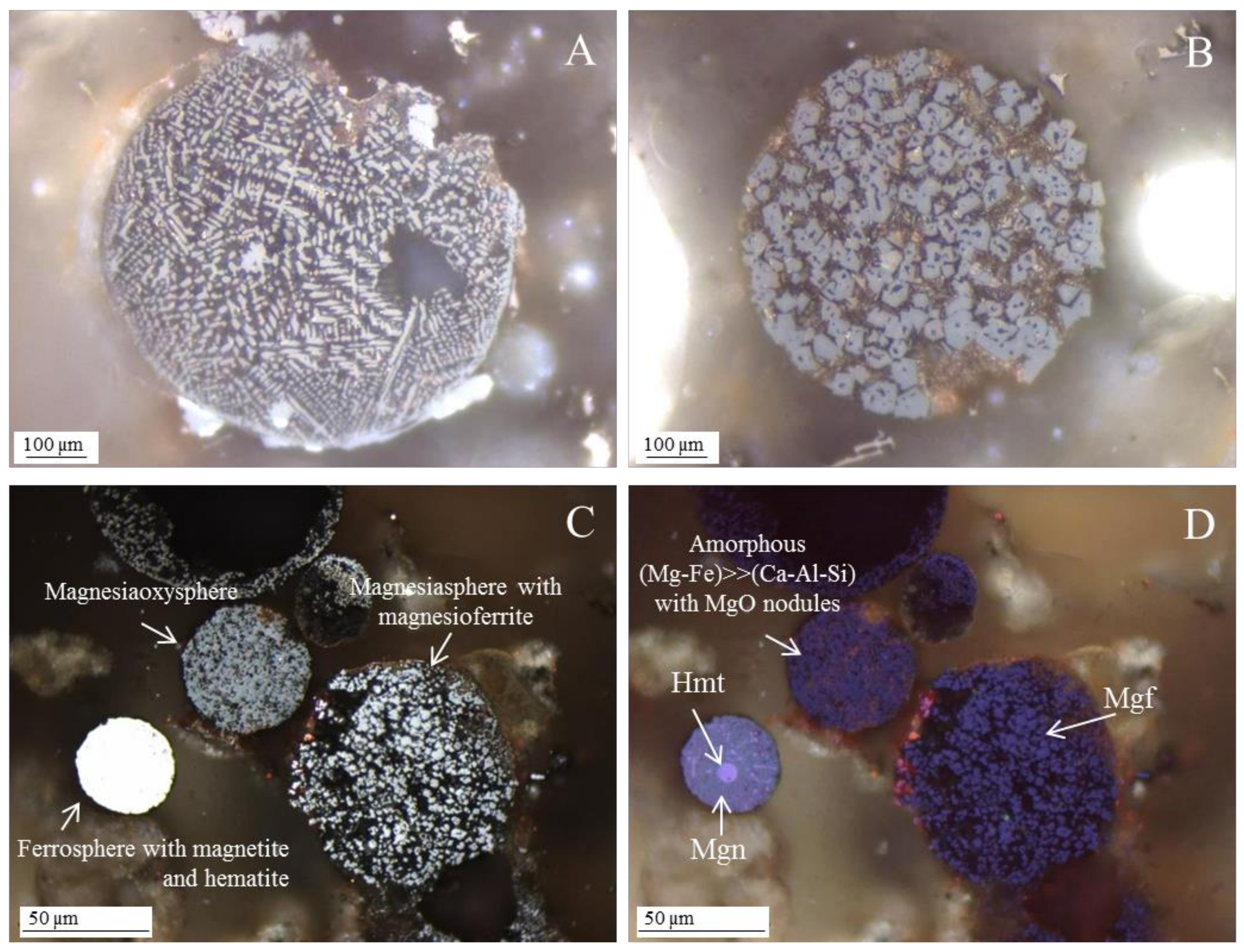
3.3. Magnesiaspheres

Magnesiaspheres are the name proposed to designate two types of FA and BA morphotypes: morphotypes with visible magnesioferrite dominating over other crystalline materials (e.g., magnetite dendrites); and morphotypes mainly composed of an amorphous material rich in Fe and Mg (Ca-poor) with visible MgO nodules or periclase.

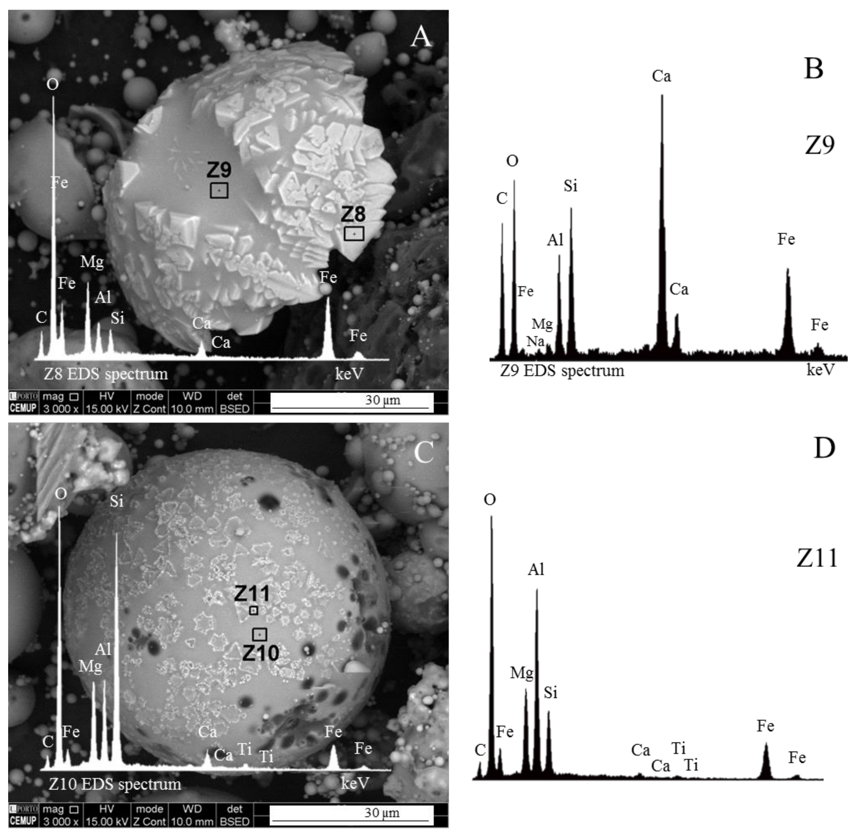
3.3.1. Magnesiapheres: Magnesiaferrospheres Type

Magnesioferrite in Coal FA

Magnesioferrite (Mg(Fe3+)2O4 is a magnesium iron oxide mineral that crystallizes as octahedral crystals of the cubic system. It is a member of the magnetite series of spinels; Mg-rich magnetite was first noted in the 1980s within the magnetic phase of coal FA by using XRD [36,37], and since then has been observed in coke particles as discrete octahedral crystals, as well as in coal slag and FA [25,26,27,31,38,39,40,41,42,43].
However, Sokol et al. [31] and Anshits et al. [44] did not classify ferrospheres with magnesioferrite as a group apart, and the internationally recognized classifications of coal FA (using reflected light microscopy with oil immersion objectives) only considers the “spinels” group [2,3,5,21,22], which includes all types of Fe-rich morphotypes.
Ferrospheres are essentially composed of Fe-rich aluminosilicate glass embedding distinctive octahedral magnetite and dendrites, and of blocky hematite. These are mostly formed following pyrite decomposition, Fe melting and further crystallization. Additionally, the EDS spectrum of these minerals has a dominant EDS Fe peak, as well as a major Fe peak in the Al–Si glassy matrix [31,44,45,46]. Therefore, Fe is clearly the only “distinctive element” in ferrospheres.
The classification of a morphotype as “ferrosphere” or “magnesiaphere” will strongly depend on the Fe and Mg concentration, and the spinel species formed: magnetite or magnesioferrite. While the amount of magnetite (Fe3O4) versus α-Fe2O3 (hematite) is dependent on the oxidation of Fe2+ into Fe3+, and given that the Fe2O3 and CaO concentration increases and the Al2O3 and SiO2 concentration decreases, the coal ash melt is determined by the following systems: FeO–SiO2–Al2O3, FeO–SiO2–Al2O3–CaO, and FeO–CaO. If the MgO concentration also increases, the systems will be FeO–SiO2–Al2O3–CaO–MgO, FeO–CaO, or CaO–MgO crystals, and the first mineral to crystallize from the melt will be a euhedral magnesioferrite [31,44].
Therefore, in these (MgO + Fe)-rich systems with magnesioferrite crystals, two morphotypes may be distinguished:
(i)
when, in relation to magnetite and hematite, magnesioferrite octahedra are residual in ferrospheres, the morphotype is classified as “ferrosphere”. In this case, Anshits et al. [44] considered that magnesioferrites are impurities occurring on the ferrosphere. Nevertheless, “ferromagnesiasphere” may be used to designate this ferrosphere variety.
(ii)
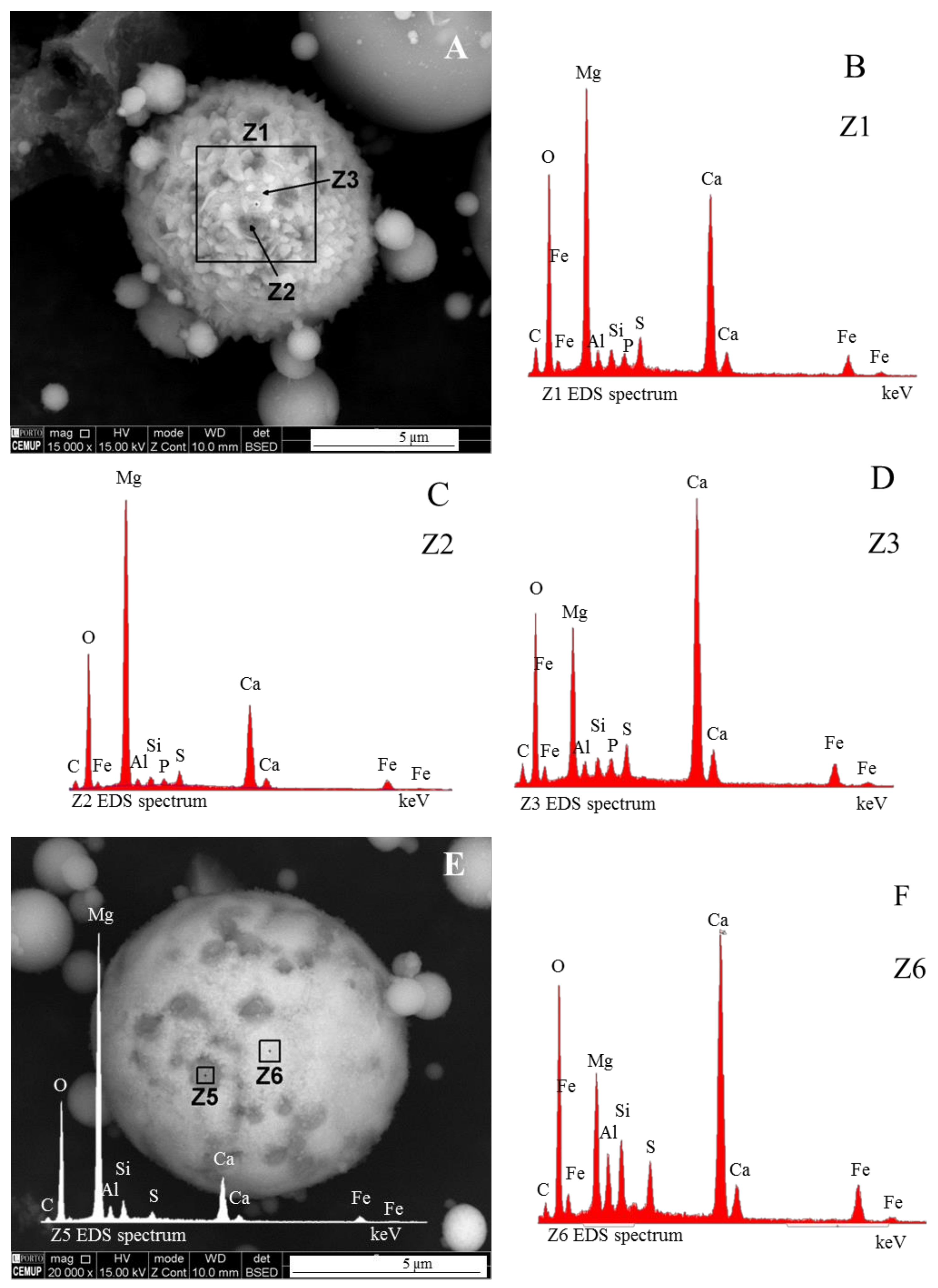
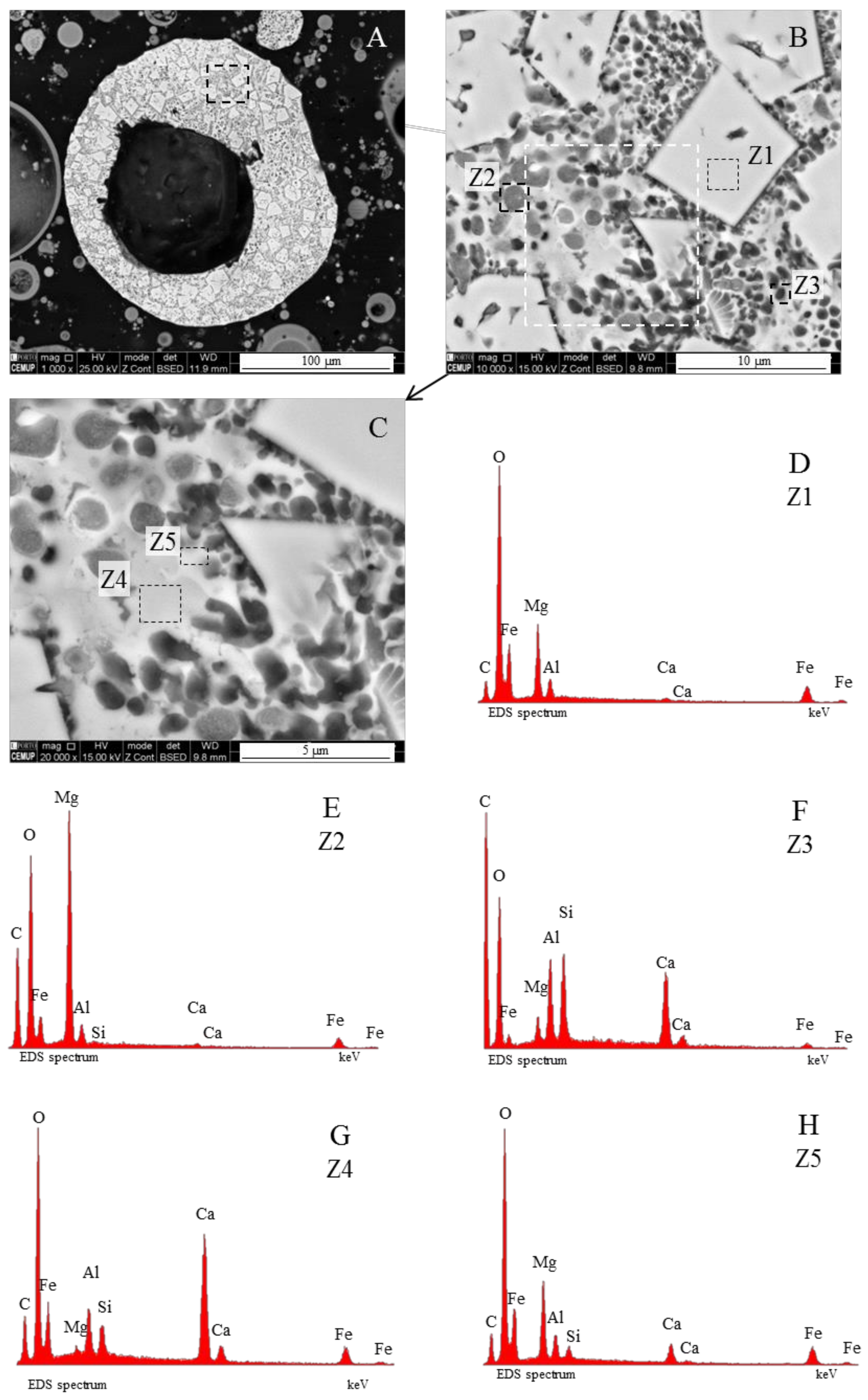
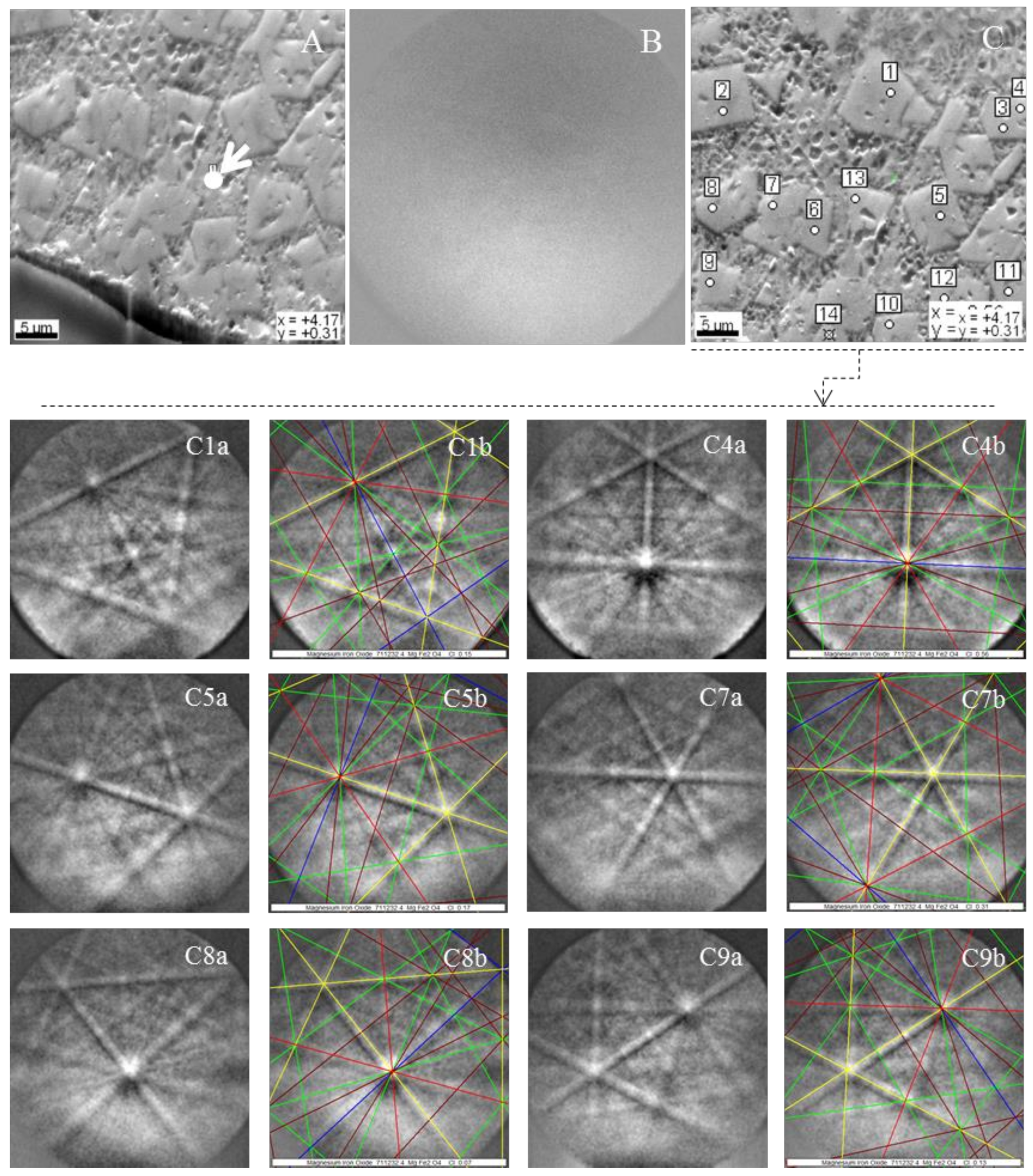
The morphotypes should be classified in the “magnesiaspheres” group and designated as “magnesiaferrospheres” when euhedral magnesioferrite (MgFe2O4) crystals are the only distinctive pattern, and magnetite dendrites and a Ca spongy structure are residual or absent. In the EDS spectrum from the magnesioferrite crystals, Mg may be the dominant peak together with Fe, and the surrounding matrix may be composed of Si, Al, Ca, and Fe associations with higher or small amounts of Mg. This seems to be the case in Choo et al. [43] when they describe round morphotypes with a crystalline ash matrix, mainly in the form of magnesioferrite (MgFe2O4) and maghemite (γ-Fe2O3) occurring in a fly ash rich in magnesioferrite.
Under reflected light microscopy using oil immersion objectives a set of fundamental differences were found between ferrospheres and magnesiaferrospheres: the presence of magnetite dendrites in ferrospheres and of magnesioferrite tetrahedrons in magnesiaferrospheres (Figure 6A,B), the higher reflectance of the ferrospheres (Figure 6C), variable Ca amounts causing yellowish reflections in magnesiaferrospheres (Figure 6B,D), the darker purple tone of magnesioferrite relative to magnetite and hematite under polarized and retarded light (Figure 6D; note: the purple tone is related to the presence of Fe).

Magnesiaferrosphere Case Study

The topography of the “magnesiaspheres” occurring in the studied FA and BA samples show magnesioferrite tetrahedrons embedded in an Al–Si or Ca–Al–Si glassy matrix with high intensity Mg and Fe EDS peaks (Figure 7A: Z8). The Ca concentration in the matrix is highly variable since the EDS spectra may show a major Ca peak or a residual one (Figure 7B: Z9 and Figure 7C: Z10). In some cases, the magnesioferrite crystals may be “skeletal”, i.e., having a major hole inside, which makes their identification less certain unless a high intensity Mg peak is present in the EDS spectrum (Figure 7C,D: Z11).
An example of a magnesiasphere (Figure 8A) studied in detail using a combination of techniques was shown to highlight the “distinctive patterns” of these morphotypes, and to contribute to a better understanding of their genesis. The results of the EBDS and Kikuchi patterns of the magnesiasphere show that the matrix is mainly composed of an amorphous material and that the crystals are constituted by magnesioferrite (Figure 9A,B, and Figure 9C1a–C9b, respectively).
Three sections of the magnesiasphere were analyzed by SEM/EDS to determine the elemental composition of specific points and areas, along a profile, to provide elemental distribution maps of the euhedral crystals and the surrounding matrix (Figure 8, Figure 10 and Figure 11). Five materials could be distinguished:
(1)
magnesioferrite crystals (Figure 8B: Z1 and Figure 8D: Z1);
(2)
periclase glass and cryptopericlase: dark-gray MgO nodules with Fe and residual Ca, Al, and Si (Figure 8B: Z2 and Figure 8E: Z2; Figure 10 profile section (1); and Figure 11A, Mg light-green round areas).
(3)
gehlenite or melilite glass and respective cryptocrystals: dark (Ca–Al–Si)·(Mg,Fe) nodules (Figure 8B: Z3 and Figure 8F: Z3; Figure 10 profile sections (2) and (3), over the dark area).
(4)
lime glass, tricalcium aluminate and calcium ferrite: Ca-rich gray material with Fe, Al, Si, and residual Mg (Figure 8C: Z4 and Figure 8G: Z4; Figure 10, profile section (3); Figure 11F);
(5)
decomposed Ca minerals and glass and magnesioferrite melt: light-gray spongy material (Mg–Fe)-rich with Al–Si and residual Ca (Figure 8C: Z5 and Figure 8H: Z5; Figure 10, profile section (5); Figure 11A,B,D,E).
However, Figure 10A,B show that these materials are distributed within three distinct areas:
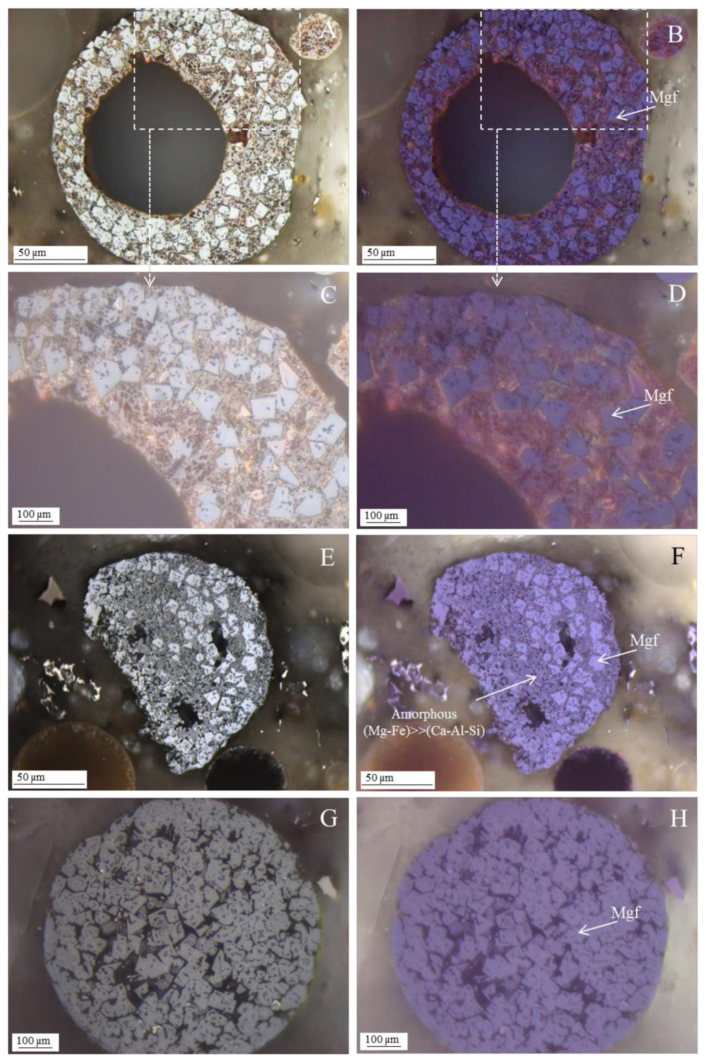
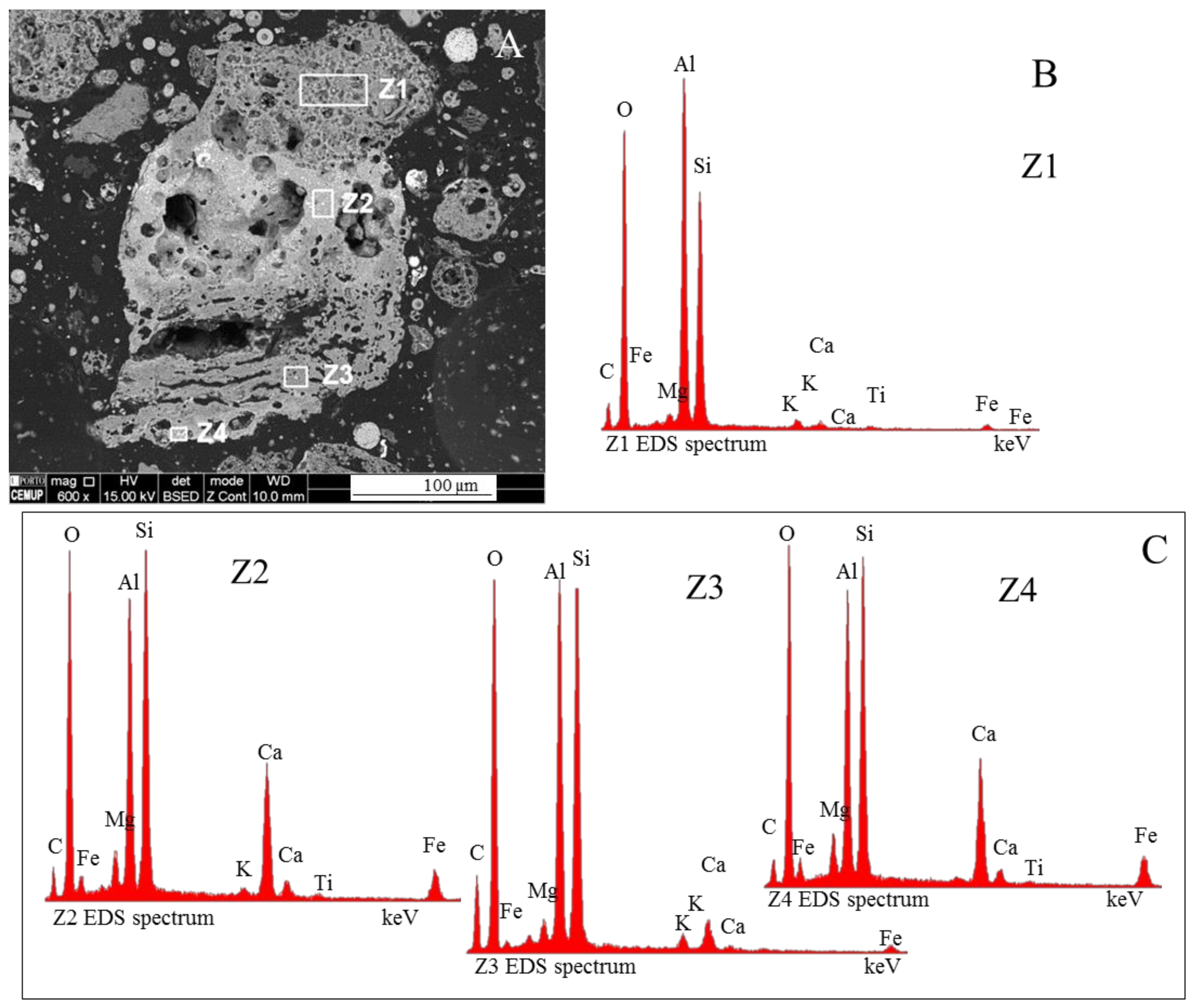
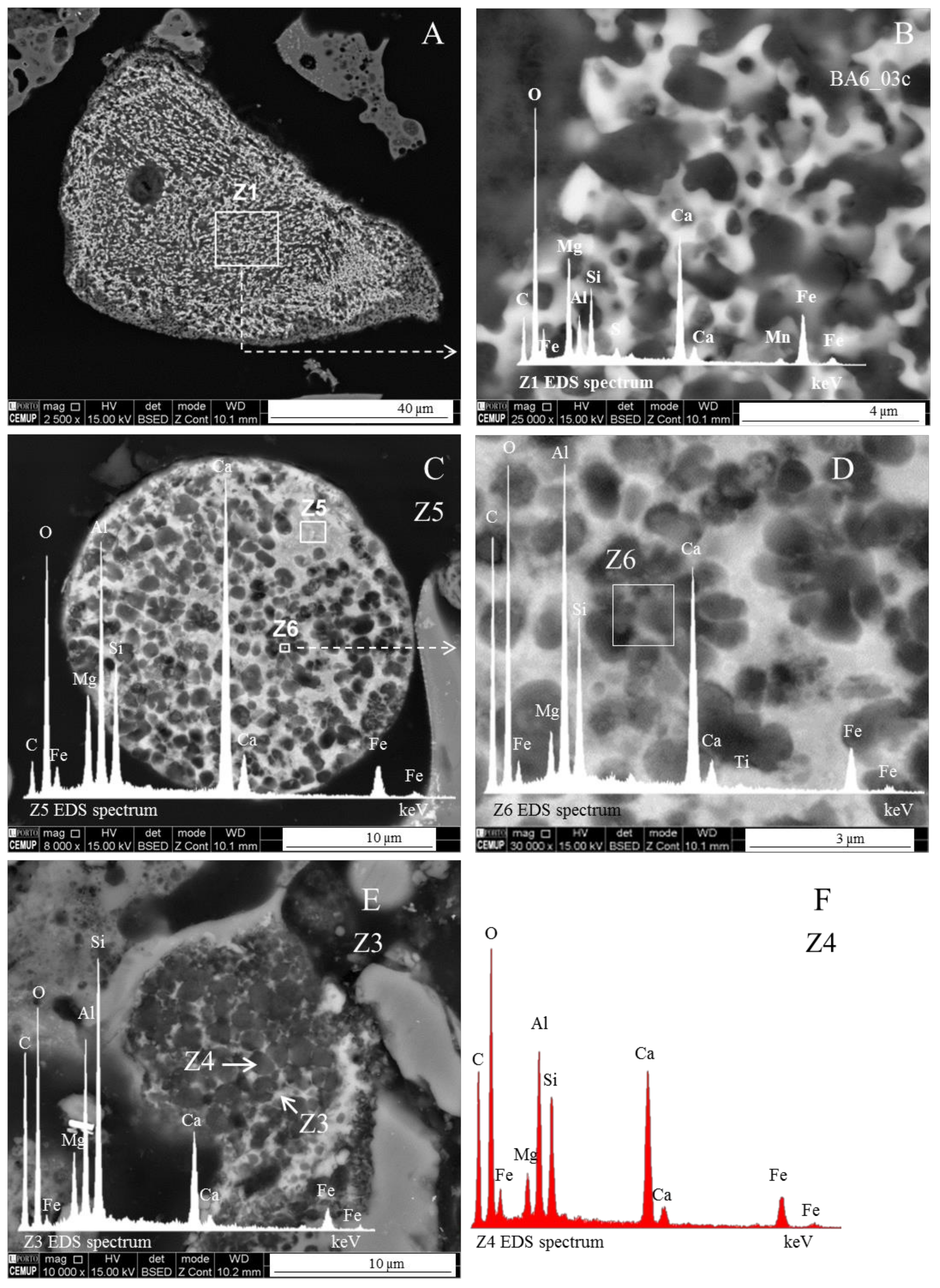
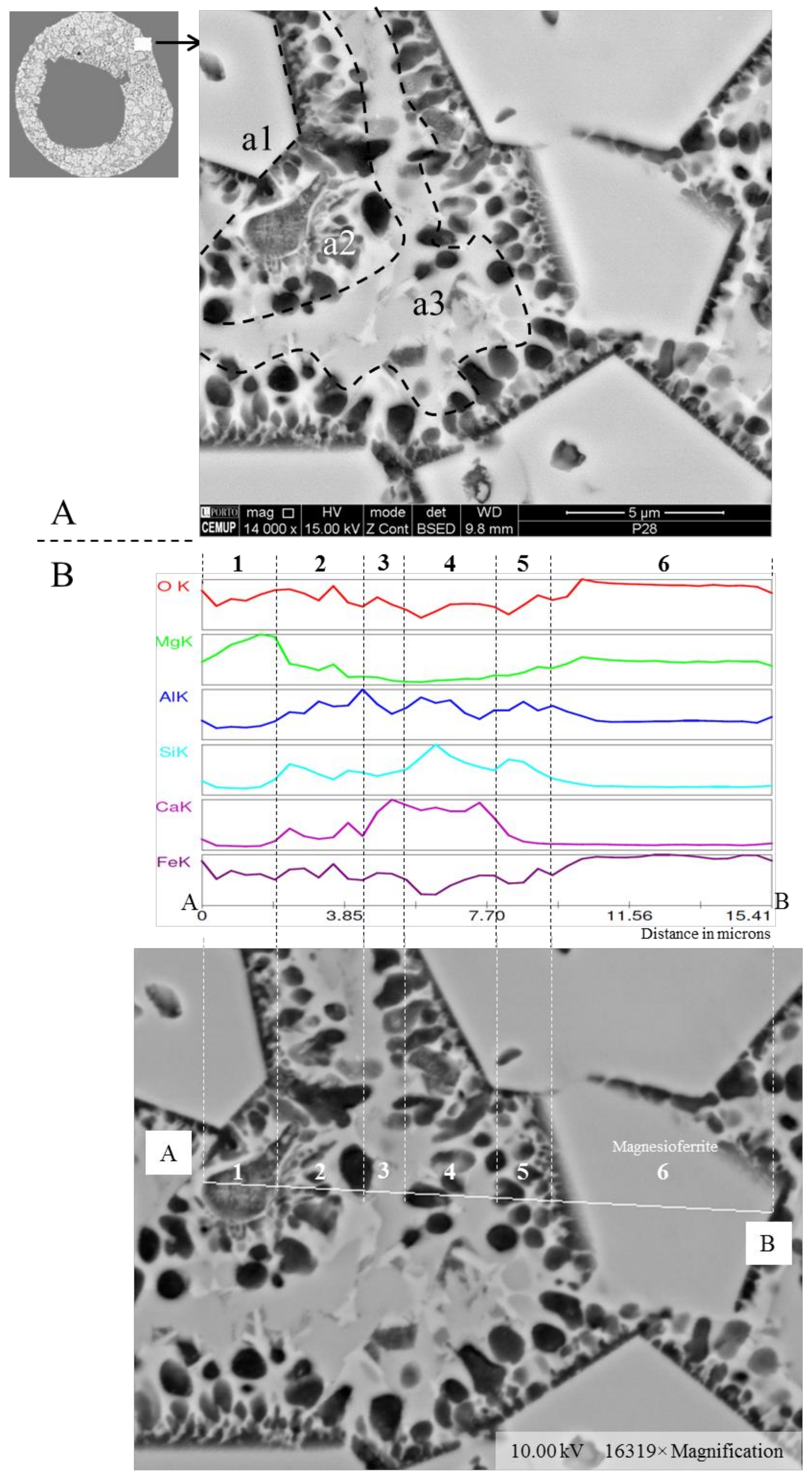
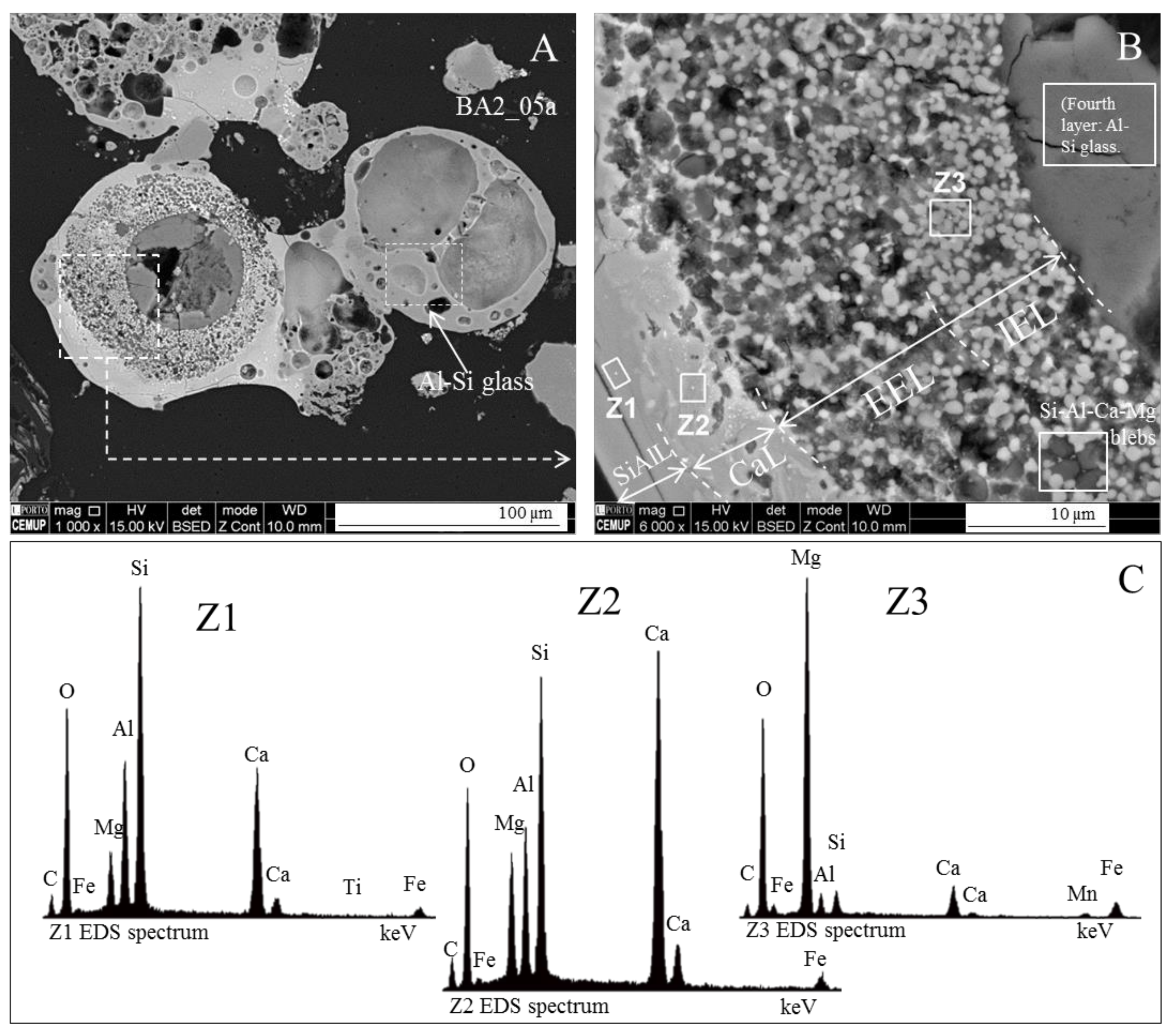
  • (area a1) Magnesioferrite crystals with Al, and residual amounts of Ca and Si. Near the edge of the crystals the amount of Al increases and the Mg and Fe decrease. This means that as the melt became depleted in Fe and Mg, more Al was incorporated into the crystal lattice;
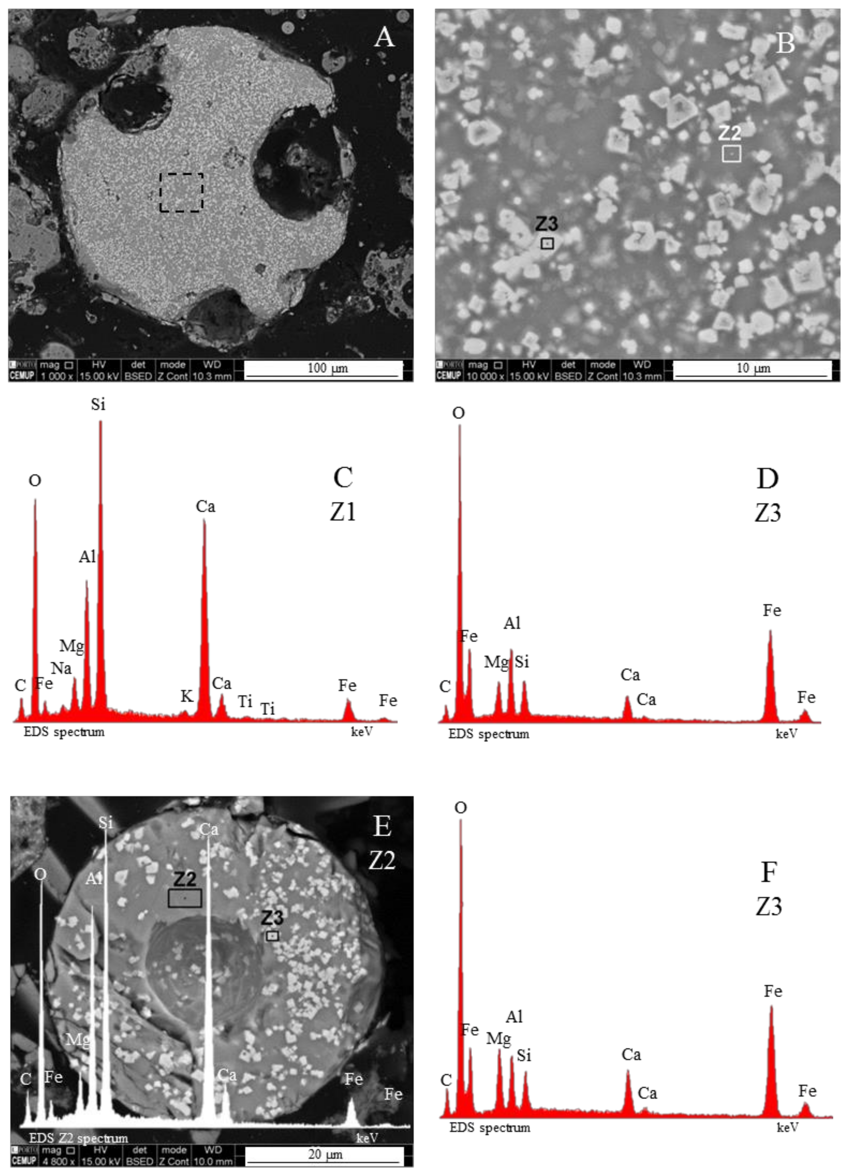
  • (area a2) Adjacent to the magnesioferrite crystals, a spongy texture reflects the reactions that occurred on a complex Ca-aluminate glass (FeO–SiO2–Al2O3–CaO–MgO) system from which several amorphous phases (e.g., periclase and (Ca–Al–Si)·(Mg,Fe) nodules) exsolved and from which magnesioferrite crystallized;
  • (area a3) In the middle, more or less equidistant to the magnesioferrite crystals, the materials show a substantial Ca, Al, and Si concentration, and the Mg is residual.
The results of the X-ray microanalysis (EDS) elemental distribution maps for Mg, Fe, O, Al, Si, and Ca carried out in a euhedral magnesioferrite crystal and the surrounding matrix (Figure 11) show the following:
(i)
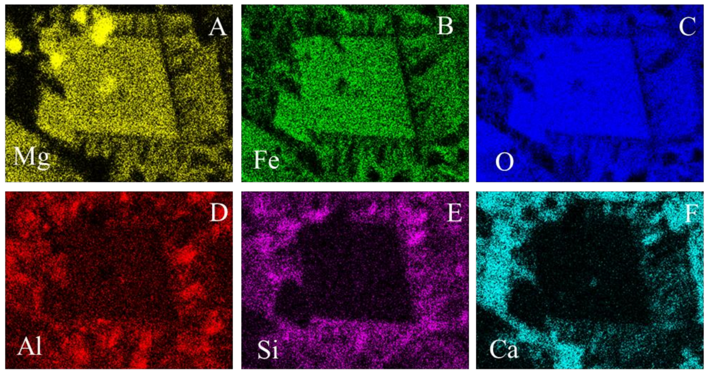
The euhedral crystal is essentially composed of Mg, Fe, and residual Al. There is an Mg rim near the crystal edge, while the Fe is homogeneously distributed (Figure 11A,B,D).
(ii)
The right and bottom sides of the crystal are surrounded by a Ca-depleted material rich in Fe and O.
(iii)
At the left side of the crystal there is a strong Ca concentration, Fe and O are depleted, and Mg is concentrated in nodules corresponding to microdroplets or periclase crystals (also observed in Wyodak–Anderson coal fly ash) [34,35] (Figure 11A,B,F).
(iv)
A cloud of Al, along with Si, surrounds the crystal. However, several high-concentration spots are clear, probably corresponding to amorphous aluminate, Ca-aluminate, Ca-aluminosilicate, and silica (Figure 11D,E).
This morphotype characterization by reflected light microscopy using oil immersion shows the morphotype under polarized light, and under polarized and retarded light (1λ) conditions (Figure 12A–D). The magnesioferrite crystals are grey under non-polarized light and purple under retarded polarized light. Both in non-polarized light and in retarded polarized light, the amorphous material surrounding the magnesioferrite crystals is irregular and darker than the crystals. Yellowish reflections are also a distinctive pattern of this amorphous material.
However, the morphotypes may contain different proportions of amorphous Mg-rich material versus crystalline magnesioferrite. Figure 12E,F shows a morphotype where the darker grey amorphous material is predominant relative to the lighter-grey magnesioferrite crystals, and Figure 12G,H shows a massive morphotype composed almost entirely of magnesioferrite crystals. In both cases the considered morphotypes should be classified as magnesiaspheres.

3.3.2. Magnesiapheres: Magnesiaoxyspheres Type

Under reflected light microscopy using oil immersion objectives a set of fundamental differences were also found between calcispheres and magnesiaoxyspheres, and between magnesiaoxyspheres and magnesiaspheres with magnesioferrite. Like magnesiaferrospheres, under the SEM BSE mode, the intermediate brightness between aluminosilicate morphotypes and ferrospheres makes magnesiaoxyspheres relatively easy to find (Figure 13A,B). However, magnesiaoxyspheres have properties between calcimagnesiaspheres and the magnesiaferrospheres (Figure 13C,D).
As explained above, when calcispheres show Mg amounts that are not residual, but not sufficient to overcome Ca distinctive patterns, the subtype is named calcimagnesiasphere (Figure 5 and Figure 14A,B). However, when the material is mainly composed of an (Fe + Mg)-rich amorphous material with the presence of MgO nodules or periclase, the Ca sugar texture and magnesioferrite are residual or absent; the morphotype is then a magnesiaoxysphere (Figure 13E,F and Figure 14C,D).

3.3.3. Borderline Magnesiaspheres

Some morphotypes are ambiguous since they show high amounts of Ca, Fe and Mg, and may be “borderline” morphotypes. This is the case when the identification of magnesioferrite, a key characteristic of magnesiaferrospheres, is uncertain, but distinctive patterns of calcispheres (e.g., Ca-spongy textures) and ferrospheres (e.g., magnetite dendrites and/or blocky hematite) are not clearly visible. Figure 7C,D: Z1 and Figure 15 show “borderline” cases where the distinctive character of these morphotypes are small (Mg–Fe)-rich crystals, with Ca–Al–Si, dispersed in a smooth Ca-aluminosilicate glassy matrix. Both morphotypes are ambiguous but they do not show distinctive calcisphere or ferrosphere patterns. Therefore, they should be classified as magnesiaferrospheres.

3.4. Calcimagnesiadermaspheres and Mixed Calcialuminosilicate Morphotypes

Several (Mg–Ca)-rich morphotypes may be very complex, forming true dermaspheres or morphotypes with alternating layers. The main distinctive pattern of (Mg–Ca)-rich dermaspheres is the inner exsolvation layer with a characteristic granular texture (Figure 16).
This exsolvation layer is divided in two: an internal Mg exsolvation layer (IEL in Figure 16B), which is marked by a higher concentration of MgO grains (probably periclase nodules and crystals), and an external exsolvation layer (EEL in Figure 16B) where the MgO grains gradually decrease and Si–Al–Ca–Mg nodules gradually increase. The Ca-spongy texture is not clearly visible in the IEL, but it becomes distinguishable in the EEL (Figure 16B: IEL and EEL).
A smooth Ca-rich layer where signs of exsolvation are very dim (Figure 16B: CaL) separates the exsolvation layer from the most externally dense Si–Al·(<<Ca + Mg) glassy layer (Figure 16B: SiAl). In this dermasphere, the element’s distribution is characterized by a decrease in Mg from the IEL to its external surface. The Ca and the Si–Al, which are nearly residual in the IEL, are the major components of the EEL and of the Ca-rich layer. However, the Ca concentration decreases in the external Si-Al layer (Figure 16B: SiAlL and Figure 16C: Z1–Z3).
While in the process of “shell-formation”, the components diffusing in the direction of the droplets are only able to precipitate in the form of a shell around the droplets [17]; during the formation of (Ca–Mg)-rich dermaspheres, the layers seem to be formed following the diffusion of the components inside the sphere, which is still in a molten stage.
On the mixed calcialuminosilicate morphotypes [Al–Si·Ca(>Mg > Fe)], the distinctive pattern is the alternation of layers with different compositions (Figure 17). In the studied samples, these morphotypes were relatively common, while calcispheres and magnesiaspheres were scarce. These mixed calcialuminosilicate morphotypes show a very irregular shape, and are essentially composed of two distinct alternating layers: dark aluminosilicate layers with small vacuoles, poor in fluxing agents such as Ca, Mg, and Fe (Figure 17A,B: Z1 and Figure 17C: Z3); and light aluminosilicate layers with large vacuoles, and with Ca(>Mg > Fe) (Figure 17A,C: Z2 and Figure 17C: Z4). The characteristics of these morphotypes indicates that they have resulted from larger inorganic particles, e.g., mixed layers of illite–smectite, which either rapidly solidified or were not heated to a high enough temperature for all layers to melt.

3.5. Systematization of Calcispheres and Magnesiaspheres in the Fly Ash Classification

In order to improve the coal fly ash and bottom ash petrographic classification, an illustrated organigram and its description is presented to help the reader visualize a systematization based on distinctive elements and patterns (Figure 18):
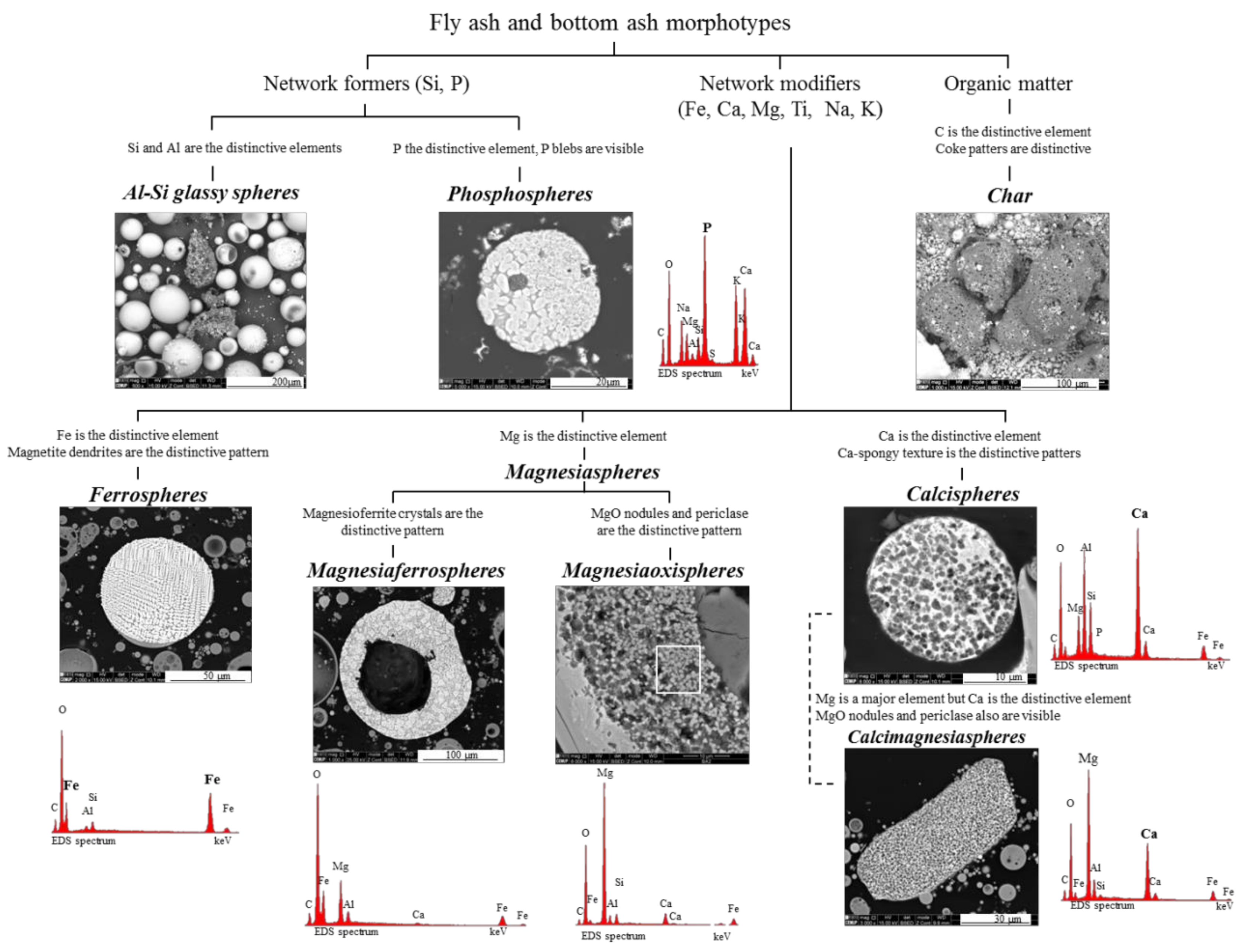
  • Network-forming elements Si, P, and C: “Al–Si glass”, “phosphospheres”, and “char”, respectively:
    Al–Si glass. The most abundant material in fly ash and bottom ash is partially baked clay, and amorphous and glassy aluminosilicate in the form of a vast array of irregular forms and glassy spheres, which reflect both the coal mineralogical composition (in general, mostly clays, carbonates and pyrite) and the combustion conditions, which influence the melt viscosity, trapped volatile matter, surface tension, and cooling rate. The glassy spheres or “Al–Si glassy spheres” are characterized by an aluminosilicate matrix embedding a skeleton of quartz and mullite [17,20,22,47,48,49,50,51];
    Phosphospheres. These morphotypes are described in Valentim et al. [28], and their “distinctive pattern” is the “pomegranate” texture caused by the phosphorus network;
    Char. A solid carbonaceous combustion residue—“char” is formed from coal organic matter during the combustion pyrolysis stage inside the furnace, where devolatilization is the main process that occurs and where oxidation is limited. During the oxidation stage, however, not all of the char burns, and coke-like particles composed of a C-rich network are either carried by the gas flow or fall to the furnace bottom, becoming a component of fly ash and bottom ash.
    The char results from the burning of low, medium and high rank coals with different macerals (vitrinite, inertinite, and liptinite). Therefore, char is a very heterogeneous material and classifications that focused on fly ash while including char were developed (e.g., [2,3]), as were detailed classifications (e.g., [5,23,52,53,54]).
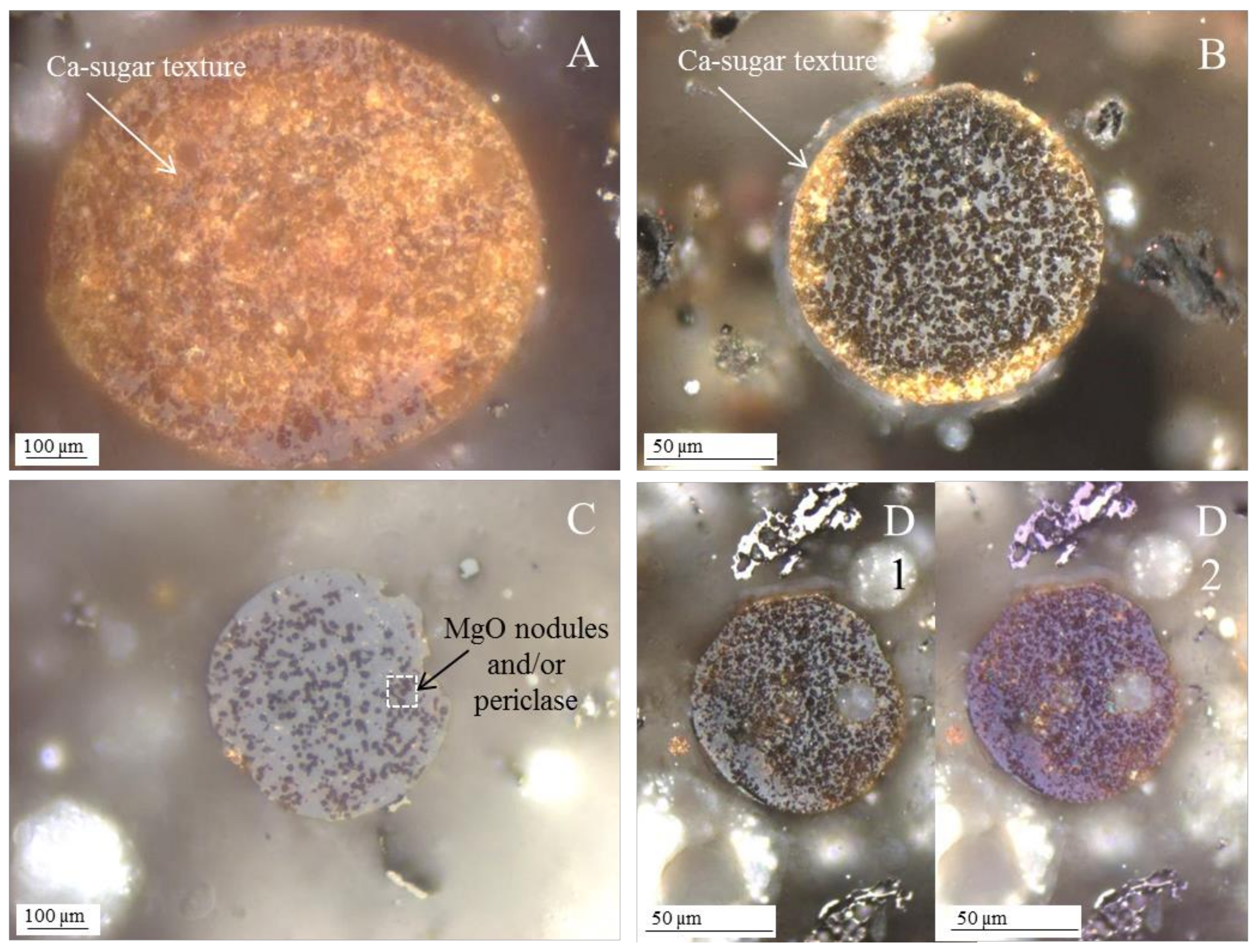
  • Network modifier elements Fe, Mg, and Ca: ferrospheres, magnesiaspheres, calcispheres, and “calcimagnesiaspheres. (Note: Na and K are also network modifiers, but examples of morphotypes with Na and K “distinctive patterns” were not found in this study.)
    Ferrospheres (magnetic microspheres or magnetite globules) are well-known iron-rich spheres with a mineralogical composition that includes quartz, mullite, magnetite, hematite, and anhydrite embedded with amorphous aluminosilicate. Fe is the distinctive element responsible for distinctively smooth, polygonal, dendritic, granular, and molten drop magnetite, hematite, and maghemite [22,45,55,56];
    Magnesiaspheres. Although it has an important Fe concentration, Mg is the “distinctive element” of the magnesiaspheres. However, these were divided into magnesiaferrospheres, if magnesioferrite crystals are not residual and are the “distinctive pattern”, and into magnesiaoxyspheres, when the morphotype is mainly formed by an (Mg–Fe)-rich amorphous material with MgO nodules and/or periclase.
    Calcispheres and calcimagnesiaspheres. The main “distinctive pattern” of “calcispheres” is a Ca-spongy structure. If a P-“pomegranate” texture is also visible, that texture is more relevant; the morphotype is then classified as a “phosphosphere”, not a “calcisphere”, because P is capable of forming its own network. However, when magnesioferrite crystals, MgO nodules or euhedral periclase are also visible without being abundant, the morphotype is a “calcimagnesiaphere”.

4. Conclusions

The present study is composed of a set of reflected light microscopy observations combined with SEM/EDS, which enabled the characterization of Ca-, Ca + Mg-, and Mg-rich morphotypes, and helped us propose a nomenclature and systematization. Although it is not entirely original, since other authors have already made detailed descriptions in the case of the FA of Wyodak–Anderson coal (Powder River Basin, WY), no nomenclature or systematization has been proposed with regards to the fly ash petrographic classification.
The nomenclature is based on distinctive elements and patterns (Ca, spongy texture, yellow rims and sugar texture for calcispheres; and Mg and magnesioferrite, or its amorphous counterpart, for magnesiaspheres), and magnesiaspheres are considered separately from ferrospheres, despite their high Fe concentration. However, complex and mixed morphotypes were also considered, since they are common to all coal FA and BA.
The systematization proposed using the criterion of the “distinctive element” and its role as a network former or fluxing agent seems like a reasonable way of systematizing the FA and BA morphotypes, since it includes previous universally accepted morphotype groups (e.g., ferrospheres and char). At the same time, it enables the addition of new morphotype species. This systematization contributes to solving the problem of the “inorganics fraction” in the fly ash petrographic classification that has recently been proposed by the International Committee for Coal and Organic Petrology [5,23].
The combination of the techniques we used provided an excellent tool and was enough to highlight differences and similarities between morphotypes. However, a detailed characterization of the mentioned minerals is still needed, and in the future computer-controlled scanning electron microscopy (CCSEM) studies (e.g., [57]) should be conducted, preferably in magnesiasphere-rich samples, in order to develop a clear classification table for the differentiation of the minerals.

Acknowledgments

2nd and 3rd ERA-MIN Joint Call (2014 and 2015), Projects RAREASH and CHARPHITE (Fundação para a Ciência e a Tecnologia, IP, Portugal; ref. ERA-MIN/0006/2014; ERA-MIN/0005/2015); Institute of Earth Sciences (ICT; FCT UID/GEO/04683/2013), COMPETE POCI-01-0145-FEDER-007690.

Author Contributions

Bruno Valentim and Georgeta Predeanu conceived the work and wrote the paper; Barbara Białecka, Mihai Cruceru, Joanna Całus-Moszko, and Luminiţa Georgeta Popescu contributed with materials and analyzed the data; Paula Alexandra Gonçalves, Alexandra Guedes, Renato Guimarães, and Ana Cláudia Santos performed the analysis and analyzed the data.

Conflicts of Interest

The authors declare no conflict of interest.

References

  1. Alvarez, D.; Borrego, A.G.; Menéndez, R. Unbiased methods for the morphological description of char structures. Fuel 1997, 76, 1241–1248. [Google Scholar] [CrossRef]
  2. Hower, J.C.; Mastalerz, M. An approach toward a combined scheme for the petrographic classification of fly ash. Energy Fuels 2001, 15, 1319–1321. [Google Scholar] [CrossRef]
  3. Hower, J.C.; Suárez-Ruiz, I.; Mastalerz, M. An approach toward a combined scheme for the petrographic classification of fly ash: Revision and clarification. Energy Fuels 2005, 19, 653–655. [Google Scholar] [CrossRef]
  4. Hower, J.C.; Groppo, J.G.; Graham, U.M.; Ward, C.R.; Kostova, I.J.; Maroto-Valer, M.M.; Dai, S. Coal-derived unburned carbons in fly ash: A review. Int. J. Coal Geol. 2017, 179, 11–27. [Google Scholar] [CrossRef]
  5. Suárez-Ruiz, I.; Valentim, B.; Borrego, A.G.; Bouzinos, A.; Flores, D.; Kalaitzidis, S.; Malinconico, M.L.; Marques, M.; Misz-Kenan, M.; Predeanu, G.; et al. Petrographic Classification of Fly Ash Components; International Committee for Coal and Organic Petrology (ICCP; www.iccop.org); Open File (www.iccop.org); International Committee for Coal and Organic Petrology (ICCP): Keiraville, NSW, Australia, 2015; ISBN 978-84-608-1416-0. [Google Scholar]
  6. Tucker, M.E. Sedimentary Petrology, 3rd ed.; Blackwell Science: Oxford, UK, 2001; p. 262. ISBN 0-632-05735-1. [Google Scholar]
  7. Ward, C.R.; French, D. Determination of glass content and estimation of glass composition in fly ash using quantitative X-ray diffractometry. Fuel 2006, 85, 2268–2277. [Google Scholar] [CrossRef]
  8. Ward, C.R. Analysis and significance of mineral matter in coal seams. Int. J. Coal Geol. 2002, 50, 135–168. [Google Scholar] [CrossRef]
  9. Ward, C.R. Analysis, origin and significance of mineral matter in coal: An updated review. Int. J. Coal Geol. 2016, 165, 1–27. [Google Scholar] [CrossRef]
  10. Dai, S.; Liu, J.; Ward, C.R.; Hower, J.C.; Xie, P.; Jiang, Y.; Hood, M.M.; O’Keefe, J.M.K.; Song, H. Petrological, geochemical, and mineralogical compositions of the low-Ge coals from the Shengli Coalfield, China: A comparative study with Ge-rich coals and a formation model for coal-hosted Ge ore deposit. Ore Geol. Rev. 2015, 71, 318–349. [Google Scholar] [CrossRef]
  11. Spears, A. The origin of tonsteins, an overview, and links with seatearths, fireclays and fragmental clay rocks. Int. J. Coal Geol. 2012, 94, 22–31. [Google Scholar] [CrossRef]
  12. Spears, A. Clay mineralogy of onshore UK Carboniferous mudrocks. Clay Miner. 2006, 41, 395–416. [Google Scholar] [CrossRef]
  13. Zachariasen, W.J. The atomic arrangement in glass. J. Am. Ceram. Soc. 1932, 54, 3841–3851. [Google Scholar] [CrossRef]
  14. Dietzel, A. Die kationenfeldstärken und ihre beziehungen zu entglasungsvorgängen, zur verbindungsbildung und zu den schmelzpunkten von silicaten. Elektrochemische 1942, 48, 9–23. [Google Scholar]
  15. MacDowell, J.F.; Beall, G.H. Immiscibility and crystallization in Al2O3-SiO2 glasses. J. Am. Ceram. Soc. 1969, 52, 17–25. [Google Scholar] [CrossRef]
  16. Vorres, K.S. Melting behavior of coal ash materials from coal ash composition. Div. Fuel Chem. 1977, 22, 118–142. [Google Scholar]
  17. Pietersen, H.S. Reactivity of Fly Ash and Slag in Cement. Ph.D. Thesis, Delft University of Technology, Delft, The Netherlands, 1993. [Google Scholar]
  18. Brindle, J.H.; McCarthy, M.J. Chemical Constraints on Fly Ash Glass Compositions. Energy Fuels 2006, 20, 2580–2585. [Google Scholar] [CrossRef]
  19. Creelman, R.A.; Ward, C.R.; Schumacher, G.; Juniper, L. Relation between coal mineral matter and deposit mineralogy in pulverized fuel furnaces. Energy Fuels 2013, 27, 5714–5724. [Google Scholar] [CrossRef]
  20. Hemmings, R.T.; Berry, E.E. On the glass in coal fly ashes: Recent advances. Mater. Res. Soc. Symp. Proc. 1988, 113, 3–38. [Google Scholar] [CrossRef]
  21. Hower, J.C.; Rathbone, R.F.; Graham, U.M.; Groppo, J.G.; Brooks, S.M.; Robl, T.L.; Medina, S.S. Approaches to the petrographic characterization of the fly ash. In Proceedings of the 11th International Coal Testing Conference, Lexington, KY, USA, 15–16 March 2018; pp. 49–54. [Google Scholar]
  22. Hower, J.C. Petrographic examination of coal-combustion fly ash. Int. J. Coal Geol. 2012, 92, 90–97. [Google Scholar] [CrossRef]
  23. Suárez-Ruiz, I.; Valentim, B.; Borrego, A.G.; Kalaitzidis, S.; Flores, D.; Malinconico, M.L.; Marques, M.; Misz-Kennan, M.; Predeanu, G.; Montes, J.R.; et al. Development of a petrographic classification of fly-ash components from coal combustion and co-combustion. (An ICCP Classification System, Fly-Ash Working Group—Commission III). Int. J. Coal Geol. 2017, 183, 188–203. [Google Scholar] [CrossRef]
  24. Dai, S.; Zhao, L.; Hower, J.C.; Johnston, M.N.; Song, W.; Wang, P.; Zhang, S. Petrology, Mineralogy, and Chemistry of Size-Fractioned Fly Ash from the Jungar Power Plant, Inner Mongolia, China, with Emphasis on the Distribution of Rare Earth Elements. Energy Fuels 2014, 28, 1502–1514. [Google Scholar] [CrossRef]
  25. O’Connor, J.T. Silicate fly ash classification based on exsolution mineralogy. In Proceedings of the 1997 International Ash Utilization Symposium, Lexington, KY, USA, 20–22 October 1997; pp. 692–699. [Google Scholar]
  26. O’Connor, J.T. U- and F-bearing phosphate-silicate fly ash grains. In Proceedings of the 1997 International Ash Utilization Symposium, Center for Applied Energy Research, Lexington, KY, USA, 20–22 October 1997; pp. 716–721. [Google Scholar]
  27. O’Connor, J.T.; Meeker, G.M. Liquidus (Ca+Mg)-rich exsolution phases in low-sulfur fly ash. In Proceedings of the 24th International Technical Conference on Coal Utilization and Fuel Systems, Clearwater, FL, USA, 8–11 March 1999; pp. 333–342. [Google Scholar]
  28. Valentim, B.; Flores, D.; Guedes, A.; Guimarães, R.; Shreya, N.; Paul, B.; Ward, C.R. Notes on the occurrence of phosphate mineral relics and spheres (phosphospheres) in coal and biomass fly ash. Int. J. Coal Geol. 2016, 154–155, 43–56. [Google Scholar] [CrossRef]
  29. ISO 7404-2. Methods for the Petrographic Analysis of Coals—Part 2: Methods of Preparing Coal Samples; International Organization for Standardization: Geneva, Switzerland, 2009. [Google Scholar]
  30. McCarthy, G.J.; Solem, J.K.; Manz, O.E.; Hassett, D.J. Use of a database of chemical, mineralogical, and physical properties of North American fly qsh to study the nature of fly ash and its utilization as a mineral admixture in concrete. In Materials Research Society Symposium Proceedings; Materials Research Society: Boston, MA, USA, 1989; Volume 178. [Google Scholar]
  31. Sokol, E.V.; Kalugin, V.M.; Nigmatulina, E.N.; Volkova, N.I.; Frenkel, A.E.; Maksimova, N.V. Ferrospheres from fly ashes of Chelyabinsk coals: Chemical composition, morphology and formation conditions. Fuel 2002, 81, 867–876. [Google Scholar] [CrossRef]
  32. Vassilev, S.V.; Vassileva, C.G.; Karayigit, A.I.; Bulut, Y.; Alastuey, A.; Querol, X. Phase-mineral and chemical composition of fractions separated from composite fly ahses at the Soma power station, Turkey. Int. J. Coal Geol. 2005, 61, 65–85. [Google Scholar] [CrossRef]
  33. Vassilev, S.V.; Baxter, D.; Vassileva, C.G. An overview of the behaviour of biomass during combustion: Part I. Phase-mineral transformations of organic and inorganic matter. Fuel 2013, 112, 391–449. [Google Scholar] [CrossRef]
  34. Brownfield, M.E.; Affolter, R.H.; Cathcart, J.D.; Brownfield, I.K.; Hower, J.C.; Stricker, G.D. Dispersed volcanic ash in feed coal and its influence on coal combustion products. In International Ash Utilization Symposium; Center for Applied Energy Research, University of Kentucky: Lexington, KY, USA, 1999; p. 61. [Google Scholar]
  35. Brownfield, M.E.; Affolter, R.H.; Cathcart, J.D.; O’Connor, J.T.; Brownfield, I.K. Characterization of feed coal and coal combustion products from power plants in Indiana and Kentucky. In Proceedings of the 24th International Technical Conference on Coal Utilization and Fuel Systems, Clearwater, FL, USA, 8–11 March 1999; pp. 989–1000. [Google Scholar]
  36. Hulett, L.D., Jr.; Weinberger, A.J.; Northcutt, K.J.; Ferguson, M. Chemical species in fly ash from coal-burning power plants. Science 1980, 210, 1356–1358. [Google Scholar] [CrossRef] [PubMed]
  37. Norton, G.A.; Markuszewski, R.; Shanks, H.R. Morphological and chemical characterization of iron-rich fly ash fractions. Environ. Sci. Technol. 1986, 20, 409–413. [Google Scholar] [CrossRef] [PubMed]
  38. Franklin, F.F.; Hooper, R.L.; Rosenberg, P.L. An unusual pyroxene, melilite, and iron oxide mineral assemblage in a coal-fire buchite from Buffalo, Wyoming. Am. Mineral. 1980, 72, 137–147. [Google Scholar]
  39. Brownfield, M.E.; Cathcart, J.D.; Affolter, R.H.; Brownfield, I.K.; Rice, C.A.; O’Connor, J.T.; Zielinski, R.A.; Bullock, J.H., Jr.; Hower, J.C.; Meeker, G.P. Characterization and Modes of Occurrence of Elements in Feed Coal and Coal Combustion Products from a Power Plant Utilizing Low-Sulfur Coal from the Powder River Basin, Wyoming: USGS Scientific Investigations Report 2004-5271. 2005. Available online: http://pubs.usgs.gov/sir/2004/5271/ (accessed on 28 March 2018).
  40. Anthony, J.W.; Bideaux, R.A.; Bladh, K.W.; Nichols, M.C. Handbook of Mineralogy; Mineralogical Society of America: Chantilly, VA, USA, 2018; Available online: http://www.handbookofmineralogy.org/ (accessed on 11 January 2018).
  41. Magiera, T.; Jabłonska, M.; Strzyszcz, Z.; Rachwał, M. Morphological and mineralogical forms of technogenic magnetic particles in industrial dusts. Atmos. Environ. 2011, 45, 281–290. [Google Scholar] [CrossRef]
  42. Magiera, T.; Mendakiewicz, M.; Szuszkiewicz, M.; Jabłonska, M.; Chróst, L. Technogenic magnetic particles in soils as evidence of historical mining and smelting activity: A case of the Brynica River Valley, Polland. Sci. Total Environ. 2016, 566–567, 536–551. [Google Scholar] [CrossRef] [PubMed]
  43. Choo, T.K.; Song, Y.; Zhang, L.; Selomulya, C.; Zhang, L. Mechanisms Underpinning the Mobilization of Iron and Magnesium Cations from Victorian Brown Coal Fly Ash. Energy Fuels 2014, 28, 4051–4061. [Google Scholar] [CrossRef]
  44. Anshits, A.G.; Sharonova, O.M.; Anshits, N.N.; Vereshchagin, S.N.; Rabchevskii, E.V.; Solovjev, A.V. Ferrospheres from fly ashes: Composition and catalytic properties in high-temperature oxidation of methane. In Proceedings of the Abstracts of the World of Coal Ash (WOCA) Conference, Denver, CO, USA, 9–12 May 2011. [Google Scholar]
  45. Lauf, R.J.; Harris, L.A.; Rawlston, S.S. Pyrite framboids as the source of magnetite spheres in fly ash. Environ. Sci. Technol. 1982, 16, 218–220. [Google Scholar] [CrossRef]
  46. Valentim, B.; Shreya, N.; Paul, B.; Gomes, C.S.; Sant’Ovaia, H.; Guedes, A.; Ribeiro, J.; Flores, D.; Pinho, S.; Ward, C.R. Characteristics of ferrospheres in fly ashes derived from Bokaro and Jharia (Jharkand, India) coals. Int. J. Coal Geol. 2016, 153, 52–74. [Google Scholar] [CrossRef]
  47. Fisher, G.L.; Prentice, B.A.; Silberman, D.; Ondov, J.M.; Biermann, A.H.; Ragaini, R.C.; McFarland, A.R. Physical and morphological studies of size-classified coal fly ash. Environ. Sci. Technol. 1978, 12, 447–451. [Google Scholar] [CrossRef]
  48. Hulett, L.D.; Weinberger, A.J. Some etching studies of the microstructure and composition of large aluminosilicate particles in fly ash from coal-burning power plants. Environ. Sci. Technol. 1980, 14, 965–970. [Google Scholar] [CrossRef] [PubMed]
  49. Anshits, A.G.; Kondratenko, E.V.; Fomenko, E.V.; Kovalev, A.M.; Anshits, N.N.; Bajukov, O.A.; Sokol, E.V.; Salanov, A.N. Novel glass crystal catalysts for the processes of methane oxidation. Catal. Today 2001, 64, 59–67. [Google Scholar] [CrossRef]
  50. Matsunaga, T.; Kim, J.K.; Hardcastle, S.; Rohatgi, P.K. Crystallinity and selected properties of fly ash particles. Mater. Sci. Eng. 2002, 325, 333–343. [Google Scholar] [CrossRef]
  51. Vassilev, S.V.; Menendez, R.; Diaz-Somoano, M.; Marinez-Tarazona, M.R. Phase-mineral and chemical composition of coal fly ashes as a basis for their multicomponent utilization. 2. Characterization of ceramic cenosphere and salt concentrates. Fuel 2004, 83, 585–603. [Google Scholar] [CrossRef]
  52. Bailey, J.G.; Tate, A.; Diessel, C.F.K.; Wall, T.F. A char morphology system with applications to coal combustion. Fuel 1990, 69, 225–239. [Google Scholar] [CrossRef]
  53. Lester, E.; Alvarez, D.; Gawronski, E.; Petersen, H.; Rosenberg, P.; Vleeskens, J.; Kwiecińska, B.; Misz, M.; Pusz, S.; Flores, D.; et al. Atlas of Char Occurrences of the Combustion Working Group-ICCP; CDrom; International Committee for Coal and Organic Petrology (ICCP): Keiraville, NSW, Australia, 2000. [Google Scholar]
  54. Lester, E.; Alvarez, D.; Borrego, A.G.; Valentim, B.; Flores, D.; Clift, D.A.; Rosenberg, P.; Kwiecińska, B.; Barranco, R.; Petersen, H.I.; et al. The procedure used to develop a coal char classification-commission III Combustion Working Group of the International Committee for Coal and Organic Petrology. Int. J. Coal Geol. 2000, 81, 333–342. [Google Scholar] [CrossRef]
  55. Sokol, E.V.; Maksimova, E.V.; Volkova, N.I.; Nigmatulina, E.N.; Frenkel, A.E. Hollow silicate microspheres from fly ashes of the chelyabinsk brown coals (the South Urals, Russia). Fuel Process. Technol. 2000, 67, 35–52. [Google Scholar] [CrossRef]
  56. Xue, Q.; Lu, S. Microstructure of ferrospheres in fly ashes: SEM, EDX and ESEM analysis. J. Zhejiang Univ. Sci. 2008, 9, 1595–1600. [Google Scholar] [CrossRef]
  57. Zhang, L.; Sato, A.; Ninomiya, Y. CCSEM analysis of ash from combustion of coal added with limestone. Fuel 2002, 81, 1499–1508. [Google Scholar] [CrossRef]
Figure 1. (A) Phosphosphere with (B) P and Ca major EDS peaks, secondary Al–Si peaks, and residual S and Fe (Polish A6 sample; SEM/EDS BSE mode; 7500×).
Minerals 08 00140 g001
Figure 2. Ca-rich spheres associated with other elements (SEM/EDS BSE mode; 15,000×; Fly ash Polish A6 sample): (A) at center, a ferrosphere having, as seen in (B) Z2 and (D) Z4, a major Ca EDS peak; (B) Z2 dendritic patterns with a clear Fe peak; and (A) Z3 and (C) Z3 indicate a Ca- and Mg-rich phosphosphere.
Minerals 08 00140 g002
Figure 3. Calcispheres’ spongy and exsolvation patterns (SEM/EDS BSE mode): (A) elongated sub-rounded calcisphere with very fine spongy pattern (Polish A6 FA sample; 2500×); (B) magnification of (A), and Z1 EDS spectra (25,000×); (C) round calcisphere with homogeneously distributed exsolvations, and Z5 EDS spectrum (Romanian R4 BA sample; 8000×); (D) magnification of exsolvation in (C) (30,000×), and Z6 EDS; (E) calcisphere mostly composed of exsolvation blebs (Z4) with residual spongy texture (EDS Z3 included) (Romanian R2 BA sample; 10,000×); and (F) EDS spectrum (Z4 in (E)).
Minerals 08 00140 g003
Figure 4. Ca-rich morphotype characteristics under reflected light oil immersion objectives. (AE) Polish A28 FA sample; F Romanian R4 BA; non-polarized light; (AC) calcispheres with a yellow rim; (D) calcisphere with an internal golden-yellow sugar texture; and (E,F) Ca-rich morphotypes with dispersed magnesioferrite crystals (Mgf).
Minerals 08 00140 g004
Figure 5. Topographic characteristics and composition of magnesiacalcispheres (SEM/EDS BSE mode; Polish sample A28): spheres with an (A) irregular and (E) smooth topography punctuated by MgO gray spots in white (Ca–Mg)-matrix crystals (A: 15,000×; E: 20,000×); (BD) show EDS spectra (Z1, Z2 and Z3) marked in (A); and (F) shows the EDS spectrum (Z6) marked in (E).
Minerals 08 00140 g005
Figure 6. Fundamental differences between ferrospheres and magnesiaspheres under reflected light oil immersion objectives (Polish A28 FA sample: (A,B) non-polarized light; Polish sample A20: (C) non-polarized light and (D) polarized and 1 λ retarded light): (A) ferrosphere with magnetite dendrites (Mgn); (B) magnesiasphere with magnesioferrite crystals; (C) Ferrosphere (left), magnesiaoxysphere (center) with amorphous (Mg–Fe) >> (Ca–Al–Si) and MgO nodules, and magnesiasphere with magnesioferrite crystals (right); (D) same as in (C), magnesiaspheres show a darker purple tone than the ferrosphere with magnetite (Mgn) and hematite (Hmt).
Minerals 08 00140 g006
Figure 7. Magnesiaspheres (SEM/EDS BSE mode): (A,B) a spherical fragment with (Mg–Fe)-crystals (magnesioferrite?) embedded in a (Ca + Fe)-aluminosilicate glass (3000×; Polish sample A28); (C,D) a magnesiasphere composed of an aluminosilicate glassy matrix (spectrum Z10) embedding (Al–Mg–Fe)-cryptocrystals (spectrum Z11) (Polish sample A28; 3000×).
Minerals 08 00140 g007
Figure 8. SEM (BSE mode) and X-ray microanalysis (EDS) of a magnesiasphere (fly ash Polish sample A28): (A) Hollow sphere with magnesioferrite crystals (1000×); (B) Magnification of dashed square area in (A), and areas analyzed by EDS (Z1: magnesioferrite crystal; Z2: periclase bleb; Z3: (Ca–Al–Si)·(Mg,Fe)-blebs) (10,000×); (C) Magnification of dashed square area in (B), and areas analyzed by EDS (Z4: Ca-rich material with Fe, Al, Si and residual Mg; Z5: magnesioferrite melt) (20,000×); and (DH) EDS spectra.
Minerals 08 00140 g008
Figure 9. Electron backscattered diffraction (EBSD) analysis of a magnesiasphere section (same as in Figure 8): (A) EBDS analysis outside (white spot in front of the arrow) the euhedral crystals; and (B) no pattern is formed, which is consistent with an amorphous material; (C) EBDS 14 points in euhedral crystals: C1a, C4a, C5a, C7a, C8a and C9a are Kikuchi patterns obtained in points 1, 4, 5, 7, 8, and 9 in (C), respectively, and “b” images the indexation (not signaled) of the Kikuchi patterns, which is consistent with magnesioferrite.
Minerals 08 00140 g009
Figure 10. SEM (BSE) and X-ray microanalysis (EDS) of the elemental profile of a section of the magnesiasphere (BSE micrograph: 10.00 kV; ×16,319; (A,B) represent the profile distance = 15.41 µm, 40 points analyzed; atomic orbital K; The colored lines are graphics with variations in intensities of chosen elements: (Red) O, oxygen; (Green) Mg, magnesium; (Blue) Al, aluminum; (Light blue) Si, silicium; (Purple) Ca, calcium; (Dark purple) Fe, iron: (A) Magnesiasphere section constituted by three areas (a1: magnesioferrite crystal; a2: (Mg–Fe)–Al–Si spongy structure with MgO glass; a3: Ca-rich Al–Si); (B) Profile section (1) Mg-rich material with some Fe; Profile section (2) (Al–Si–Fe)-rich dark spots; Profile section (3) Ca-rich material with residual Mg; Profile section (4) (Ca–Si–Al)-rich material with residual Mg; Profile section (5) (Si–Al)-rich material with Fe and Mg, and residual Ca; Profile section (6) Mg– (Fe oxide) crystal (magnesioferrite).
Minerals 08 00140 g010
Figure 11. X-ray microanalysis (EDS) elemental distribution maps of a magnesiasphere euhedral crystal and the surrounding matrix (long side of the pictures: 20 µm). (AF) elemental maps of Mg, Fe, O, Al, Si, and Ca, respectively.
Minerals 08 00140 g011
Figure 12. Magnesiaspheres (oil immersion reflected white light microscopy; right column: non-polarized; left column: polarized light with 1 λ retarder plate; Polish sample A28): (AD) hollow magnesiasphere with dispersed magnesioferrite crystals (Mgf); (E,F) fragment of magnesiasphere with magnesioferrite (Mgf) and amorphous Mg–Fe; and (G,H) dense magnesiasphere almost entirely composed of magnesioferrite (Mgf).
Minerals 08 00140 g012
Figure 13. Calcimagnesiasphere, magnesiaferrosphere and magnesiaoxysphere (SEM/EDS BSE mode; Romanian BA: (A,C) sample R24; (E) sample R7): (A) Intermediate brightness morphotypes (200×); (B) EDS spectrum (Z1) of aluminosilicate in (A); (C) calcimagnesiasphere (3000×); (D) magnesiaferrosphere (1750×); and (E,F) magnesiaoxysphere (4000×).
Minerals 08 00140 g013
Figure 14. Fundamental differences between calcispheres and magnesiaoxyspheres under reflected light oil immersion objectives (Polish FA sample A28: (A,C,D); Romanian BA R4 sample: (B); Non-polarized light: (AC) and (D1,D2) polarized and 1 λ retarded light): (A) calcisphere with Ca-sugar texture, and minor amount of amorphous Fe–Mg material; (B) calcimagnesiasphere with Ca-sugar texture rim and minor amounts of amorphous Fe–Mg material; (C) magnesiaoxysphere mostly composed of amorphous Fe–Mg material with dispersed MgO nodules and/or periclase; and (D) composite image of a magnesiaoxysphere with residual Ca-sugar texture.
Minerals 08 00140 g014
Figure 15. “Borderline” magnesiaspheres (SEM/EDS BSE mode): (A) bottom ash Romanian R10 sample (1000×); (B) Magnification of dashed square area in (A), and areas analyzed by EDS (10,000×); (C,D) EDS spectra made in (B); (E) bottom ash Romanian R16 sample, areas analyzed by EDS, and EDS Z2 (1000×); and (F) EDS Z3 spectra made in (E).
Minerals 08 00140 g015
Figure 16. Calcimagnesiadermasphere (SEM/EDS BSE mode; Polish bottom ash sample BA2): (A) multilayered morphotype (left; ×1000); (B) magnification of dashed square in (A) (×6000) with marked EDS areas and the distribution of the layers: internal exsolvation layer (IEL; EDS Z1) of MgO (probably periclase blebs and crystals); external exsolvation layer (EEL) of Si–Al–Ca–Mg blebs; Ca-rich layer (CaL; EDS Z2) with irregular texture; Si–Al with Ca >> Mg (SiAlL; EDS Z3) is the external layer and has a dense structure; and (C) EDS spectra Z1, Z2, and Z3 made in (B).
Minerals 08 00140 g016
Figure 17. Mixed calcialuminosilicate morphotype (SEM/EDS BSE mode; bottom ash Romanian sample R8): (A) irregularly shaped morphotype with alternating layers of aluminosilicate (Z1 and Z3) and aluminosilicate, with Ca(>Mg > Fe; Z2 and Z4) (×600); (B,C) EDS spectra Z1, Z2, and Z3 made in (A).
Minerals 08 00140 g017
Figure 18. Systematization of calcispheres and magnesiaspheres in the fly ash classification.
Minerals 08 00140 g018
Table 1. Chemical analysis data for major element oxides in ash samples, determined by X-ray fluorescence spectrometry (%).
SampleSiO2Al2O3TiO2Fe2O3Mn3O4CaOMgONa2OK2OP2O5SO3LOI *
R247.2720.920.838.150.067.632.530.521.770.170.379.24
R447.4820.560.828.680.078.222.600.491.790.180.477.59
R746.5720.660.828.210.067.682.520.481.760.170.359.17
R847.3520.560.818.580.078.152.610.541.810.180.468.30
R1047.7820.760.848.640.078.192.640.531.820.180.537.51
R1644.8219.480.8012.170.0812.102.970.501.450.210.774.89
R2448.4620.810.828.640.078.252.690.531.840.180.458.60
A648.9926.171.079.550.093.902.451.502.650.330.711.90
A2051.6228.141.216.340.073.022.371.323.350.630.282.13
A2851.0421.920.986.080.113.322.531.042.670.170.108.82
Z649.8623.300.9315.300.093.742.190.802.240.210.430.79
* LOI = Loss on ignition at 1050 °C, consists of unburnt fuel.
Table 2. Mineral phases in the samples, determined by X-ray diffraction (wt %).
SampleR2R4R7R8R10R16R24A6A20A28Z6
Phase wt %
Quartz9.18.26.87.27.86.18.96.15.29.18.4
Cristobalite 0.30.30.20.30.30.2
Mullite5.06.14.44.45.14.65.613.219.113.614.3
Anorthite12.08.88.48.18.99.810.3 3.6
Melilite1.71.21.01.10.71.51.5
Diopside2.00.90.80.91.01.61.8
Lime 0.2
Calcite1.81.31.31.11.51.21.5 0.4
Anhydrite 0.50.20.2
Gypsum1.51.51.81.74.01.52.5
Hematite0.80.60.70.60.60.40.80.80.30.11.6
Magnetite0.30.00.10.10.10.50.41.30.20.10.3
Maghemite0.80.90.70.70.91.30.91.11.60.60.8
Spinel, ferroan0.30.00.10.10.10.30.5 0.9
Periclase 0.50.6
Grossular 0.10.30.20.20.20.4
Amorphous64.770.173.273.669.070.864.776.972.775.869.8

