
An Innovative Longwall Mining Technology in Tangshan Coal Mine, China


1
College of Resource and Safety Engineering, China University of Mining and Technology (Beijing), Beijing 100083, China
2
Department of Mining and Mineral Resources, Southern Illinois University, Carbondale, IL 62901, USA
*
Author to whom correspondence should be addressed.
Minerals 2017, 7(1), 14; https://doi.org/10.3390/min7010014
Submission received: 16 November 2016
/
Revised: 14 December 2016
/
Accepted: 16 January 2017
/
Published: 23 January 2017
Abstract
:In mining of inclined coal seams in Tangshan coal mine of Kailuan group, gateways on either end of a panel were both typically located along the floor and a gateway pillar between adjoining panels was left unmined between adjacent panels to ensure stability, thus forming a planar mining system. According to the practice, however, it turned out that this conventional mining system has long-standing problems, such as face end support problems, coal bumps, sliding of mining equipment downhill, spontaneous combustions, support problems in development entries, etc. In view of this situation and based on the No. Y294 panel, this paper analyzes an innovative mining technology in which the gateways on either end of a panel are located at different heights within the coal seam. For the adjacent panel, the gate development may be superposed on the development entry of the previous panel or may be offset with respect to it. Field data shows that the split-level layout of the longwall panel plays an effective role in control of overall stability of mining equipment in inclined coal seams. Physical modeling demonstrates that the new technology has many advantages in ground control. Under the condition without a pillar, development entry adjacent to the new panel is located in the de-stressed zone and stress concentration is significantly reduced with associated reduction in coal bumps, bursts and support problems which means less support and maintenance requirement and cost. Compared with the conventional rectangular pillar, the gateway pillar width in this new technology is effectively reduced when pillars have to be left unmined. Roof strata behavior and features are analyzed. Corresponding operations in the field are introduced in detail.
1. Introduction
Thick coal seams are widely spread over most provinces and regions in China [1]. Conventional longwall top coal caving (CLTCC) is the main mining method throughout the country [2]. However, problems such as low recovery, fire, coal bumps and bursts, wavy surface subsidence, etc., constrain its development and practical application [1]. The application of CLTCC in inclined coal seams is more difficult due to severe longwall equipment stability problems [3,4].
Kailuan group is the oldest coal mining corporation in China with a history of over 120 years [5]. Tangshan coal mine is one of the most important coal mines for Kailuan group and is a typical example of many coal mines in China. Development entries on both ends of a panel in the coal mine were typically located along the floor, and coal pillars were left unmined between adjacent panels to ensure stability, thus forming a planar mining system [6]. However, CLTCC practice shows that employing this conventional mining system gives rise to many problems to be analyzed later.
The No. Y294 panel is located in level No. 11 in Yuexu District and the thickness of the integrated coal seam of No. 8 and No. 9 is 8.7 m, cover depth is from −550 m to −658 m, dip angle is 30° on average. The panel is 90 m wide and 1028 m long; the type of shield used in working face is ZQF6200-16/32; the face end shield is ZQFG6200-20/32. Other equipment is MG300/730-QW shearer, SGZ-730/400 front AFC (Armoured Face Conveyor), SGZ-960/750 rear AFC. SZZ-960/375 stage loader and SSJ-1200/2 × 200 belt conveyor. The type of support used in the gateways is an arched steel set. The characteristics of the coal seam and surrounding rock strata are shown in Table 1.
According to the geological condition and past practice, there are four main problems:
- (1)
- Large inclination, 30° on average, which leads to longwall equipment slide.
- (2)
- Cover depth is from −550 m to −658 m, and ground pressure is relatively high.
- (3)
- In order to avoid high side abutment pressure, a large gateway pillar has to be left between adjacent panels leading to low recovery. Moreover, top coal on the top of four shields on each end of the face and gateways cannot be recovered, which further leads to low recovery.
- (4)
- Coal bumps, rock bursts and severe convergence occur frequently in the gateway only a gateway pillar away from gob due to side abutment pressure, leading to support problems and even un-serviceable result of the gateway.
2. Mining Methods
2.1. Conventional Method
According to the practice of Tangshan coal mine, mining methods employed in the past were fully mechanized multi-slice longwall mining (MLM) and fully mechanized CLTCC. However, aforementioned problems kept being encountered. The two mining methods are shown in Figure 1.
In order to avoid the abutment pressure, MLM gateways in lower slices were inner offset with respect to the upper slice as shown in Figure 1b. However, the main problems of this method are:
- (1)
- Machines in the face tend to slide due to inclination;
- (2)
- A large gateway pillar must be left unmined between adjoining panels, leading to low recovery;
- (3)
- Practice shows that MLM cannot achieve high productivity and high efficiency as tunneling work amount was large, longwall move was frequent and upper gob was repeatedly influenced by mining activity of the lower slices leading to spontaneous combustion and fires within the gob.
As shown in Figure 1c, even though CLTCC saves a large amount of material consumption, reduces the number of longwall move and tunneling work amount, many problems still exist:
- (1)
- Low recovery: Practice shows that failing to extract top coal above gateways and above face end shields and large coal pillars led to low recovery, making it hard to meet the requirement of 75% of recovery for a longwall panel by law in China.
- (2)
- Stability problems: As coal seam inclination is up to 30° on average, shields tend to slide or topple down, and shearer and conveyor tend to slide, too.
- (3)
- Support problems in gateways. As gateways in CLTCC were driven along the floor, their roof was relatively soft coal and roof falls were frequent. In addition, due to the gateway pillar, stress concentration not only occurred on the pillar, but also transferred to the gateways leading to severe deformation and support difficulties in gateways.
- (4)
- Spontaneous combustion: Coal loss employing CLTCC gives rise to spontaneous combustion, especially in loose coal lost in gob. There were a few spontaneous combustion prone areas such as high coal roof failure areas of the gateways which accounted for two-thirds of fire disasters in the coal mine, and two ends of working face where top coal failed to be extracted and other locations where the amount of coal loss was large.
2.2. The New Strategy
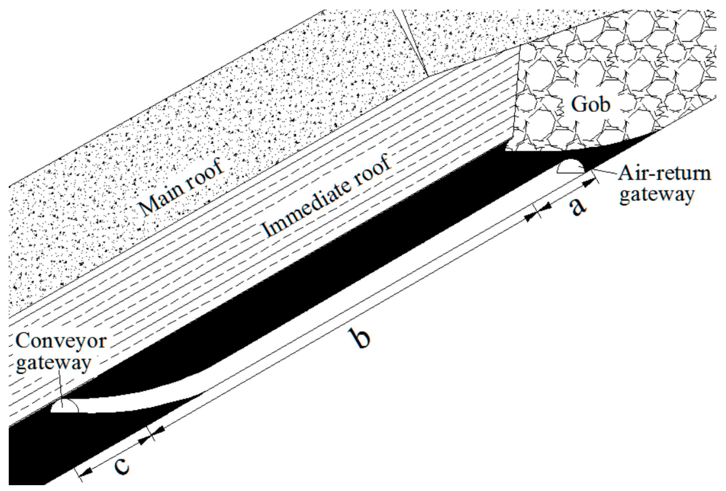
The novel approach “Longwall Mining with Split-level Gateways (LMSG)”, which is an innovative patent invented by Dr. Zhao, J.L in 1998 at China University of Mining and Technology (Beijing) [7,8], is being employed for the coal mine of interest as shown in Figure 2. The gateways on either end are located at different heights within the coal seam. The air-return gateway is driven along the floor while the conveyor gateway is driven along the roof. Thus, the mining geometry consists of a gradually incline-to-flat polygonal-line transitional section on one end of the panel (Panel 1). For the adjacent panel (Panel 2), the gate development may be superposed on the development entry of Panel 1 or may be offset horizontally with respect to it, which depends on the geological condition or other engineering requirements. The transitional section is developed incrementally by adjusting the inclination of each section of AFC, shields and other production machines. The length and inclination of each section of AFC also depend on either the geological condition or other field engineering requirements. Shield transition is shown in Figure 3.
2.3. Mining Operations in the LMSG
Mining operations in the LMSG are unique and termed Triple Sections Mining Technology (TSMT) [9], as shown in Figure 4.
The working of section “b” is performed under the artificial roof, the pseudo-roof or the regenerated roof which has steel mesh underneath and is constructed when mining the upper level of the same section of the previous panel. Thus, the tunneling work of the air-return gateway is done under the steel wire mesh and a fraction of the coal extraction is also done under the steel wire mesh. Steel sets are used for supporting the air-return gateway. Thus, it is supported by steel sets with wire mesh on the top preventing the caved rock fragments from falling. Mining operations in section “b” are similar to CLTCC, while working of section “c” is similar to multi-slicing longwall mining technology. The shield support has a wire mesh laying device on the top to form an artificial roof for the next section “a” of the future panel [10,11]. The operations of the three sections above constitute a working cycle for one LMSG panel.
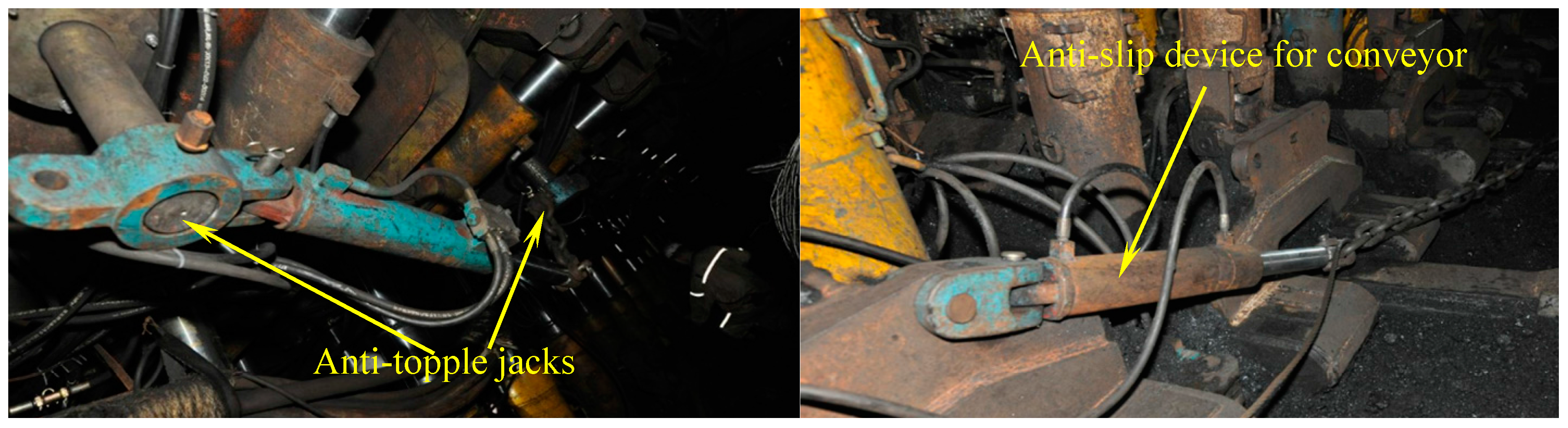
Besides using LMSG to increase stability, other supplementary measures are taken to prevent mining equipment from sliding downhill in face in order to double guarantee the safety of the longwall equipment, facility and personnel. These measures mainly include mounting an anti-slip device for the conveyor and an anti-topple device for the shields, adjusting the pseudo-inclined amount of the working face, etc. These measures solve the stability problems of the equipment, roof control problems, stones flying off, etc., in inclined working face. Some measures are shown in Figure 5.
2.4. Panel Continuance
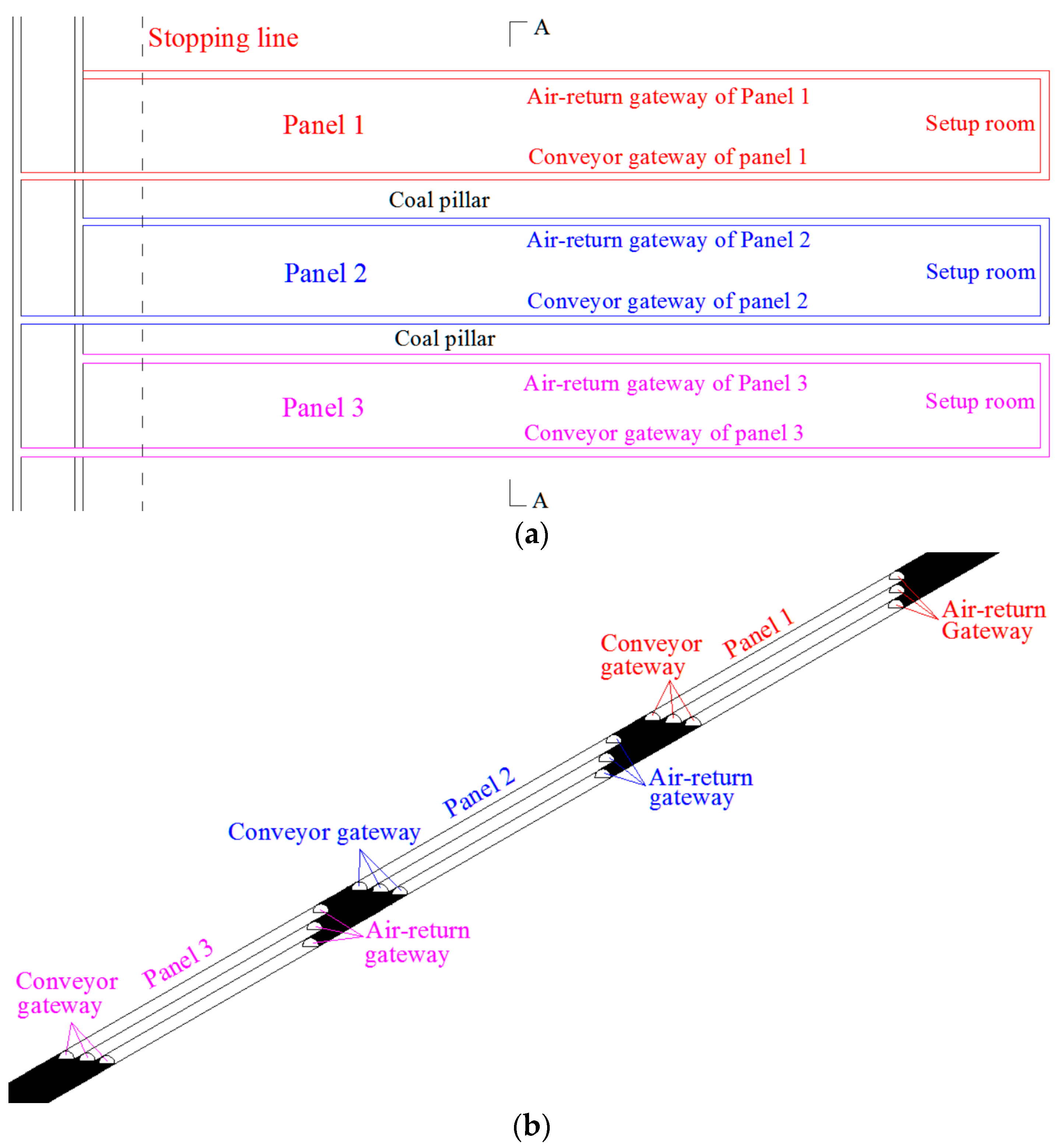
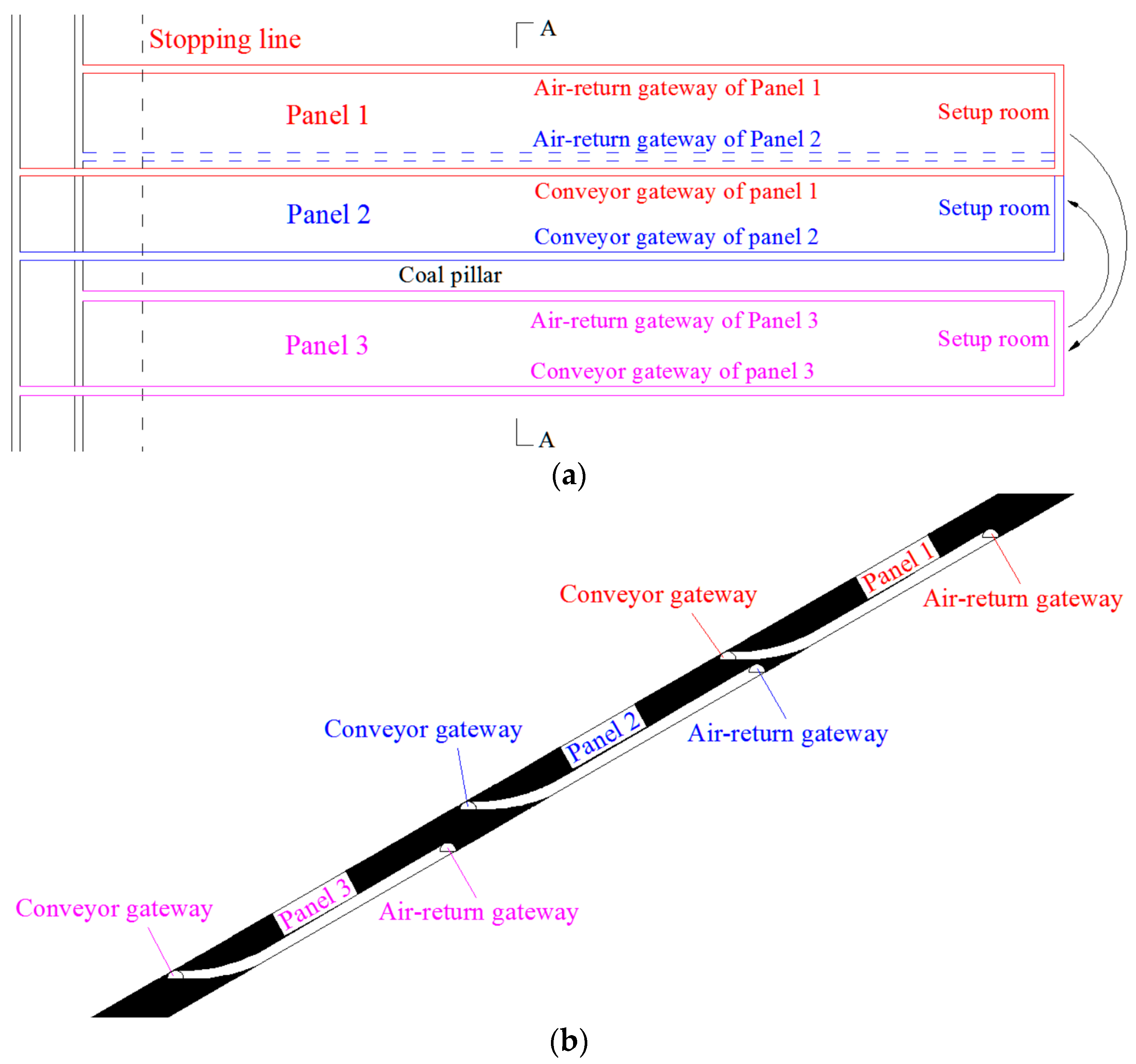
As the gob-side gateway of the successive new panel is driven directly under the artificial roof or the pseudo-roof of the edge of the previously longwall-mined panel, the tunneling work should be done at least 6 months (preferably one year) after the previous panel is mined out. This delayed time is required to allow the broken rock strata to settle and heal [12]. Figure 6 shows a panel continuance plan for three panels.
As we can see, using the sequence given in Figure 6, Panel 2 becomes the so-called island longwall after Panel 1 and Panel 3 are mined; this will lead to a high likelihood of coal bumps and rock bursts for the gateway next to the gob. However, as the air-return gateway of Panel 2 is going to be driven under the gob edge of Panel 1 where it is destressed, a coal pillar is not needed to protect it. As the conveyor gateway of Panel 2 has to be driven along the roof, a coal pillar has to be left unmined between Panel 2 and Panel 3 in order to protect the conveyor gateway of Panel 2 next to the gob of Panel 3.
The concerns regarding LMSG will be discussed later.
3. Advantages of the Technology and Concerns
3.1. Advantages
According to the practice of Tangshan coal mine, the new strategy has many advantages compared with the conventional ones (MLM and CLTCC), mainly including:
(1) High recovery.
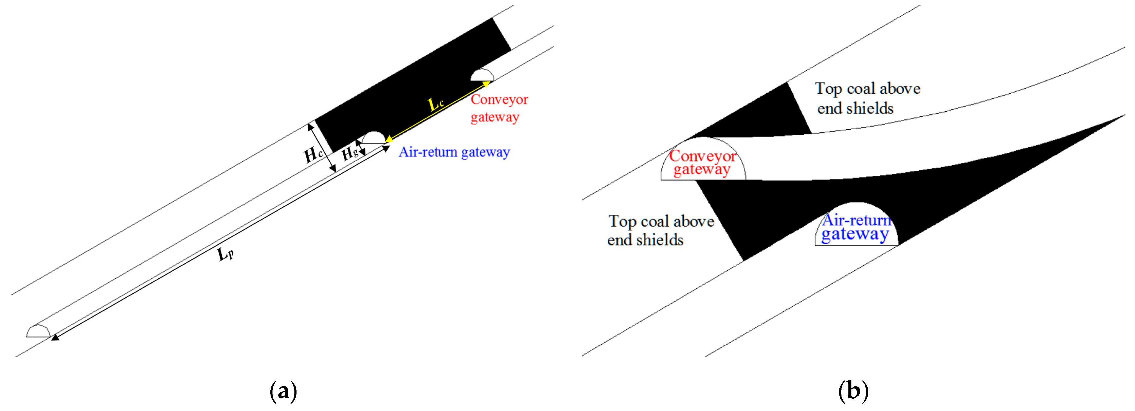
As we can see from Figure 7, the pillarless LMSG has no conventional rectangular gateway pillar but only a small triangular coal loss. Gateway pillar loss and top coal that fail to be extracted above gateways in CLTCC are shown in Figure 7a. Assume that the top coal above four end shields is not recovered, the width of each shield is 1.5 m, the height of the gateway is Hg, the width of the coal pillar is Lc, coal seam thickness is Hc, panel width is Lp, then the CLTCC panel recovery ratio η can be calculated by Equation (1):
In Tangshan coal mine, Hg is 3 m, Lc is 20 m, Hc is 8.7 m, Lp is 90 m, thus coal loss is calculated as 242.4 m2, and η = 74.7%, which is just below the 75% that is required by law in China.
While coal loss in the LMSG is significantly reduced as shown in Figure 7b. Top coal above end shields is approximately 15.6 m2, and triangular coal loss is approximately 10 m2. Since the length of the panel is 1028 m, and the volume of total coal that can be recovered using LMSG for one panel is (242.4 − 25.6) × 1028 = 222,870.4 m3, the total amount is 222,870.4 m3 × 1.48 t/m3 = 329,848.2 t, increasing recovery by 14.4% as shown in Table 2.
(2) Easier gateway tunneling and maintenance.
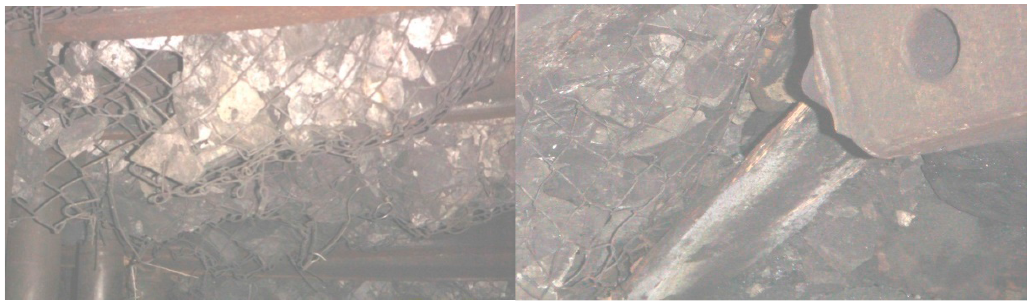
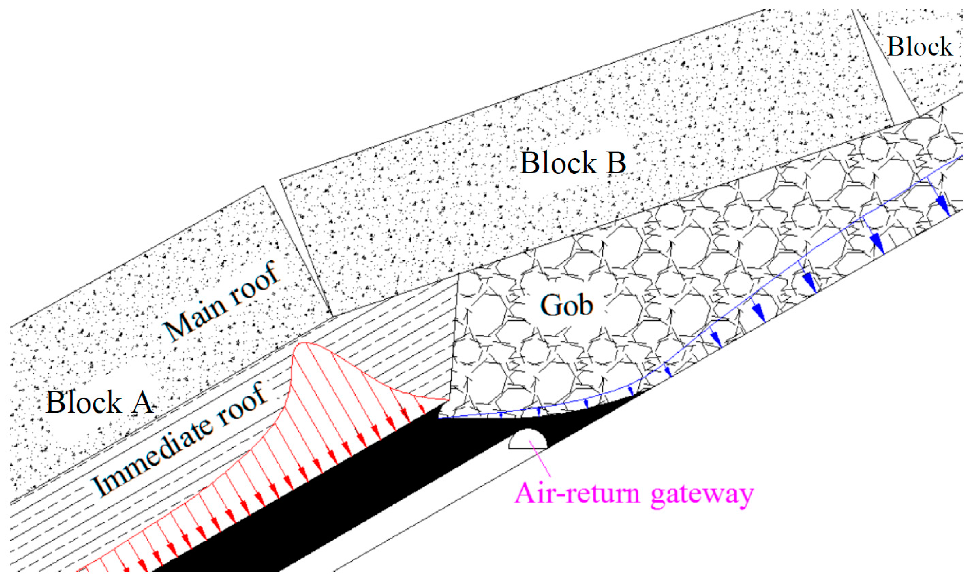
The conveyor gateway in the LMSG is driven along the roof. Hence, the roof is no longer coal but solid rock which is much more competent, leading to a better roof support condition and less requirement. However, the conveyor gateway is driven right under the re-compacted gob edge of the previous panel, i.e., it is located within the destressed zone of the super-adjacent panel. Note that there is a solid coal or coal sheet in the roof of the conveyor gateway and it is not totally connected to the gob. This is better for ventilation and to some extent reduces the air leakage compared with when it is completely connected to the gob. The tunneling work of the conveyor gateway is actually performed under this thin solid coal roof and two sides of the conveyor gateway are solid coal (one side is the rib of the triangular coal pillar, the other side is the rib of the solid coalbed). Thus, the gateway supported by steel sets with wire mesh on the top prevents the roof from falling. Figure 8 shows the artificial roof support in the conveyor gateway completely connected to the gob and caved rocks right behind the face end shields in Zhenchengdi coal mine, China. Thus, the support system has to be designed to carry only the load of caved rock mass resulting from the caved immediate roof which is less required [13]. Figure 9 shows that the air-return gateway is right under the masonry protective structure developed by the main roof. As we can see, the conveyor gateway is located in the most destressed part of the whole panel system which minimizes ground control problems here.
(3) Reduction of probability of spontaneous combustion and fire.
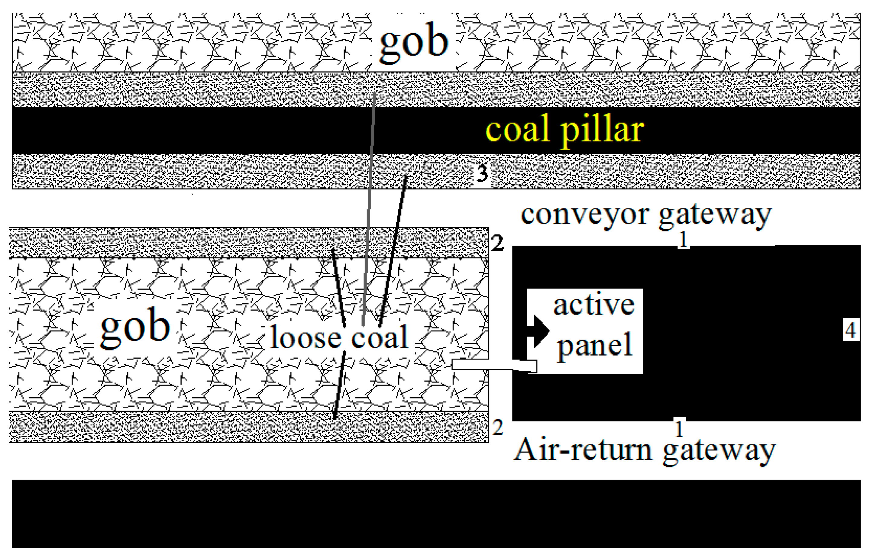
In CLTCC, top coal above the gateways and several face end shields cannot be extracted and gateway pillars gradually fail and break due to abutment pressure, leading to a large amount of loose coal. These broken loose coal pieces, fragments and gravel result in a high probability of spontaneous combustion. The spontaneous combustion-prone areas are shown in Figure 10. Area 1—the ribs of the gateway; Area 2—two ends of the face; Area 3—beside coal pillars; Area 4—beside the barrier pillar.
Fortunately, in LMSG, the face end adjacent to area 3 gradually becomes flat, hence the thickness of the top coal decreases which means that the recovery ratio of top coal is higher than CLTCC, i.e., the closer to the conveyor gateway 1, the smaller the amount of the coal loss; the farther to the conveyor gateway 1, the larger the amount of the coal loss, up to the same amount as that in CLTCC, as shown in Figure 7. The loose coal adjacent to the air-return gateway is now solid triangular coal loss which has a certain function for separating loose coal from the active panel. Thus, spontaneous combustion-prone areas and their threat substantially reduce.
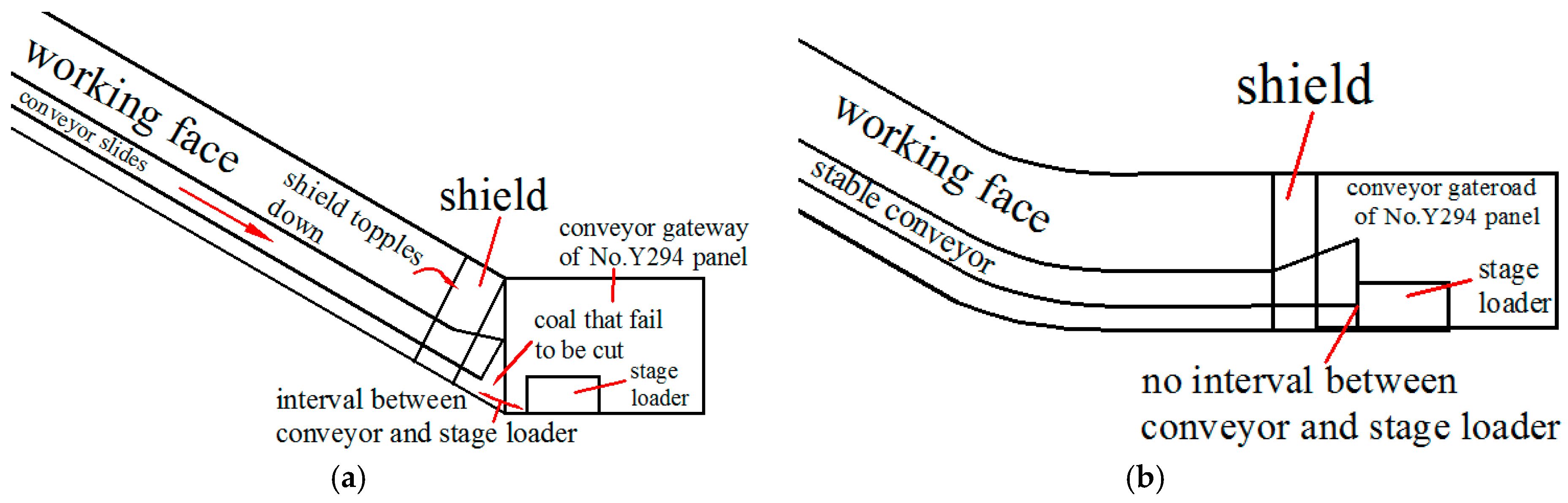
The coal seam in Tangshan coal mine is up to 30° on average, and equipment in face tends to slide in CLTCC due to inclination. In LMSG, shields uphill are subject to resistance from the shields in the incline-to-flat transitional section, so is AFC, thus machines in face are more stable. Moreover, the disconnection of the conveyor and the stage loader is avoided and the coal within the interval can be completely cut by a shearer as shown in Figure 11.
3.2. Concerns and Constraints
Since the invention of LMSG, dozens of coal mines have adopted the method. According to practice of this method in these coal mines, LMSG has been successfully employed in coal seams with inclination from 0° to 60° [13]. LMSG is applicable for coal seams with thickness preferably over 3 m, but is not limited to seams more than 3 m. With the development of tunneling technology, rock tunnels can now be driven at relatively lower cost, therefore, with a gateway driven in the roof rock bed, LMSG in the thin coal bed can also achieve high yield and high efficiency as shown in Figure 12.
It is preferably used for a coal seam with low methane content and gob water amount. Many researchers argue that tunneling under the gob is a challenge. In reality, from Figure 4, we can see that there is solid coal or a coal sheet in the roof of the air-return gateway and it is not totally connected to the gob. In addition, the principle of mining sequences, shown in Figure 6, is to leave enough time for the gob area of the previous panel to compact and get cementation again in order to form a pseudo-roof with competent strength for subsequent panels similar to MLM. In some engineering practices where the air-return gateway is totally connected to the gob, by grouting slime water into the gob area from the conveyor gateway, the degree of consolidation is increased, making sure that the air leakage meets the ventilation requirement. In addition, grouting slime reduces the spontaneous heating of loose coal in the gob area which means that the prevention and extinguishing of fire are also pretty good. A number of LMSG practices in many coal mines in China [10,13] corroborate the above statement.
In cases of accumulated water or large gas content or concentrations in the gob, engineers should consider the case shown in Figure 13.
From the analysis above, we can see that it is inevitable to leave pillars unmined between adjacent LMSG panels in some cases. However, it also has some merits in pillar design in the LMSG which will be discussed in detail in the next section.
3.3. Pillar Design in the LMSG
The width of the gateway pillars in China has long been calculated by Equation (2) [12,13,14,15]:
where, B = width of the gateway pillar; x0 = width of the plastic zone adjacent to the gob; m = mining height; x1 = the width of the plastic zone adjacent to the next new roadway. x0 satisfies:
where, f = the coefficient of friction; = the angle of internal friction; C = cohesion; γ = unit weight; H = cover depth; K = stress concentration factor; .
B = x0 + 2m + x1
Since the mining height “m” is reduced significantly in Equation (3) in the Tangshan case, the mining height adjacent to the conveyor gateway is approximately 3 m as shown in Figure 8, while that in CLTCC is equal to 8.7 m. Thus, x0 in the LMSG is only about one-third of that in CLTCC, leading to a smaller pillar width B in Equation (2).
4. Physical Modelling of the LMSG Panel for Tangshan Coal Mine
Physical modelling is an effective way to study rock strata behavior and has been extensively used in China [16]. Large-scale 2-D physical models were built in China University of Mining and Technology (Beijing) for Tangshan coal mine. According to the field data of the No. Y294 panel, the developed engineering properties are given in Table 3 and were used to develop equivalent model materials properties. Strength, density and geometry similitude for equivalent model materials follow the following relationships [17]:
and CL, Cσ and Cρ were calculated as follows:
where CL is the geometric scaling constant, Cσ is a constant of strength similarity and Cρ is a constant of density similarity between the prototype (full-scale case) and the model. Subscript p represents the prototype, m represents the model, L is the length, σ is the strength and ρ is the bulk density.
Equivalent model materials used consisted of aggregate (fine sand) and cement materials (lime and Plaster of Paris). The geometric scaling factor of CL = 200:1, and the density factor of Cρ = 1.6:1 were used for physical modeling studies. Using Equations (4) and (5), equivalent material parameters were obtained and the proportion of different constituents in the physical model are given in Table 4. CM-2B type static strain gages were embedded into model materials to measure strains at strategic locations that were built during the construction stage and then converted to stress values.
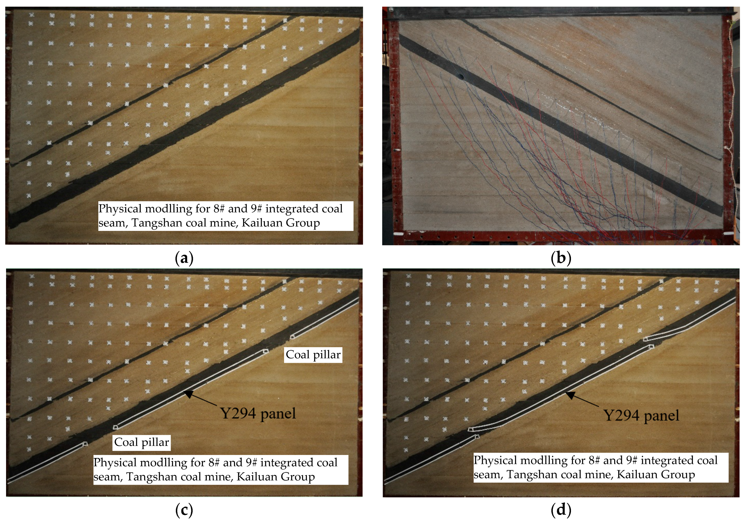
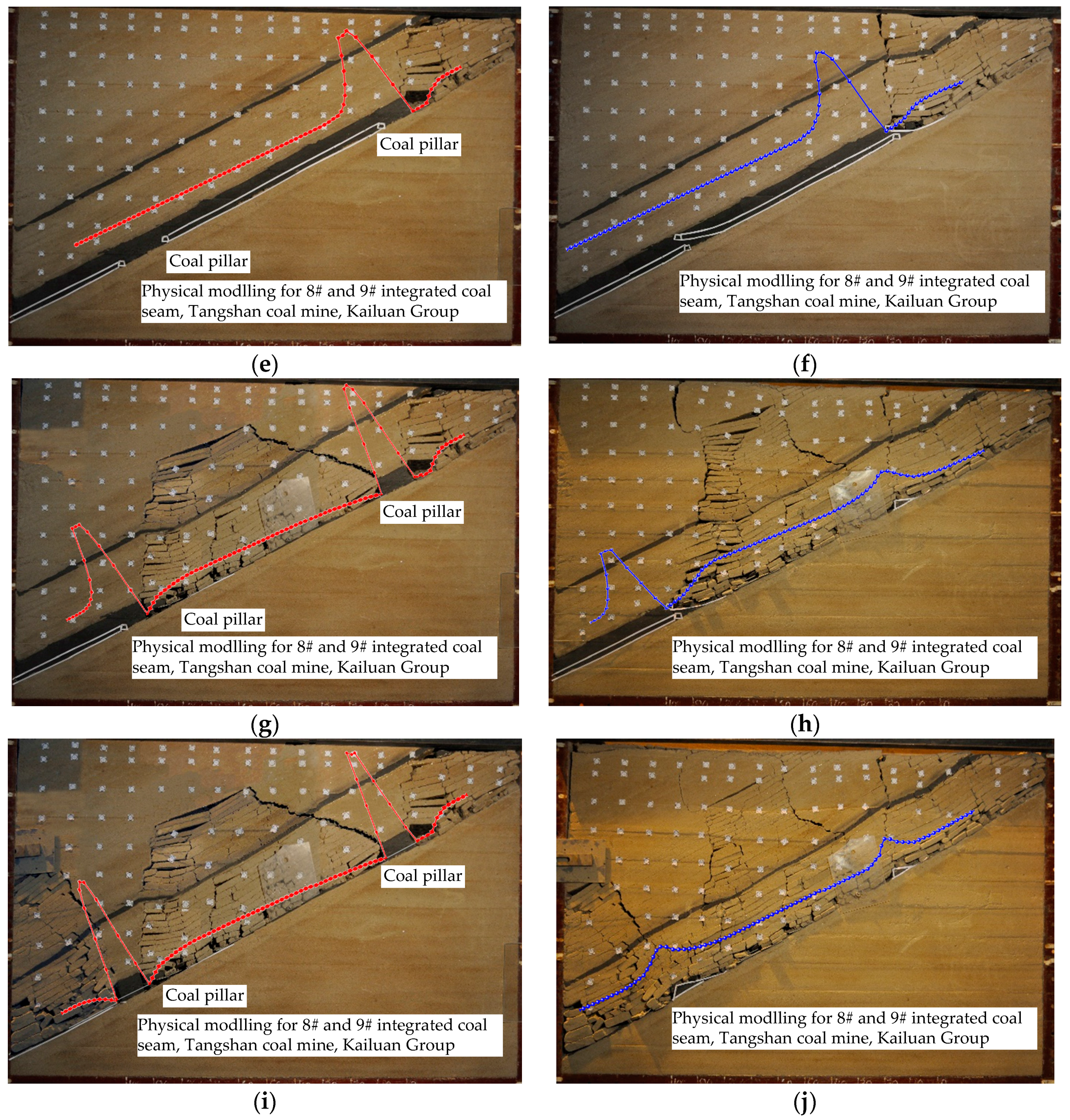
The dimensions of the physical models were 180 cm long, 160 cm thick and 1300 cm high and simulated mining depth and panel widths were 500 m and 100 m, respectively as shown in Figure 14a. Plane-stress simulations were used. Stress concentration in abutment zones was measured using stress sensors and a digital data acquisition system as shown in Figure 14b. The panel layouts for CLTCC and LMSG are shown in Figure 14c,d. In the CLTCC model, a 20 m wide coal pillar was left unmined between adjacent panels, while in the LMSG model, only a triangular pillar was developed due to the unique panel layout of LMSG. The panel excavation of the models and corresponding stress distribution are shown in Figure 14e–j.
5. Analysis and Discussion of Physical Modeling Results
From Figure 14e,f, we can see that in LMSG, as the working face on one end gradually translates from incline into flat, the roof strata move or deform more continuously or uninterruptedly as the roof strata in CLTCC are more abrupt and the void ratio is accordingly larger. Stress distributions of the two approaches are similar with only some slight differences in gob edges and abutment pressures. As a bridge structure forms adjacent to the coal pillar during the excavation of the previous CLTCC panel, the gob pressure remains zero for a few meters. While in the LMSG, the gob edge pressure is near zero which is likely due to the transition section that is also covered by a few caved rocks. However, the overall pressure around here is substantially reduced due to structures formed by roof strata (Figure 9).
After excavation of the Y294 panel (Figure 14g,h), we can see that since there is no conventional rectangular pillar between two adjacent LMSG panels (only a small triangular coal loss which has little effect on strata movement), the overlying strata across the LMSG panels deform and subside as a whole as if it is a super-critical longwall panel which is beneficial for mitigating non-uniform deformation on the ground surface, as shown in Figure 14h,j. In addition, as the overlying strata across the LMSG panels deform and subside as a whole, there is no apparent abutment pressure, while in CLTCC, huge abutment pressure occurs on the coal pillar as shown in Figure 14g which likely gives rise to bumps and bursts. From Figure 14h, we can see that as the pressure in the gob is generated only by the caved strata below the relatively intact key stratum, stresses are less than pre-mining vertical stress. The small remnant triangular coal pillar has little effect on stress distribution in the gob. Thus, the gob is more uniformly loaded with slightly higher gob pressure in LMSG. A few meters within the gob edge, the stress is significantly reduced even below the other parts of the gob. Therefore, the air-return gateway of the successive new panel is always located in this most destressed zone in the whole mining system and therefore ground control problems should be minimum; while in CLTCC, with the depth increases, the abutment pressure that occurred on the deeper pillar is larger, as shown in Figure 14i.
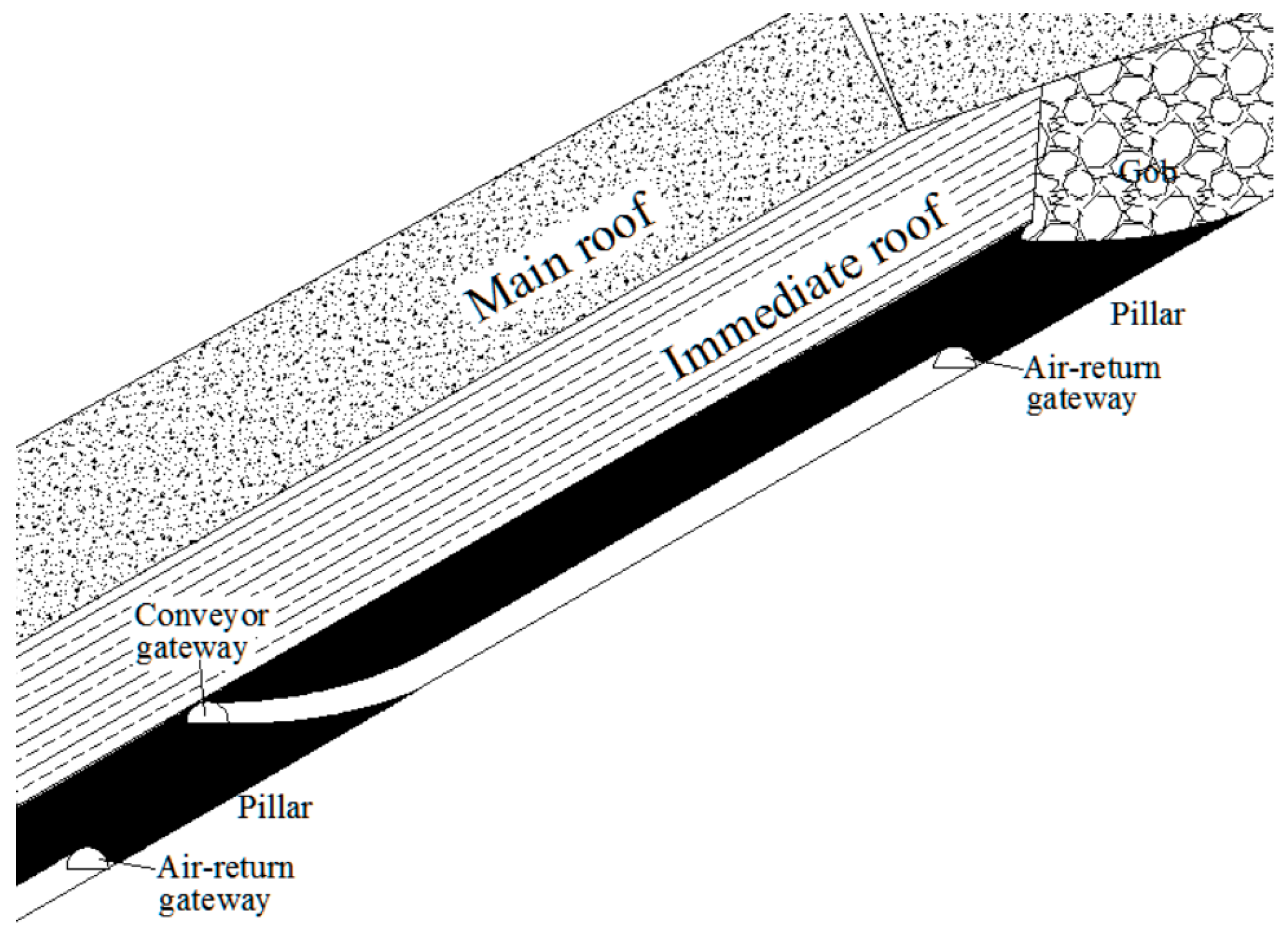
Figure 14f shows that the air-return gateway of the Y294 panel is located right under the edge of the gob of the previous panel and is adjacent to the triangular coal pillar. A protective arch structure is developed above the air-return gateway, as shown more clearly in Figure 9. The overlapped part is right under the protective structure formed by the main roof strata. Block C is supported by the gob material which is settled. Block A is in the pre-mining state and is intact. Block B is therefore like a bridge, with one end supported by block C and gob, one end supported by block A and immediate roof. This concept is similar to the concept that the safest place in a room during an earthquake is a corner where a bridge protective structure is likely to form. The stress around this air-return gateway is much lower than pre-mining stress as shown in Figure 9. Thus, the likelihood of ground control problems is minimized.
6. Concluding Remarks
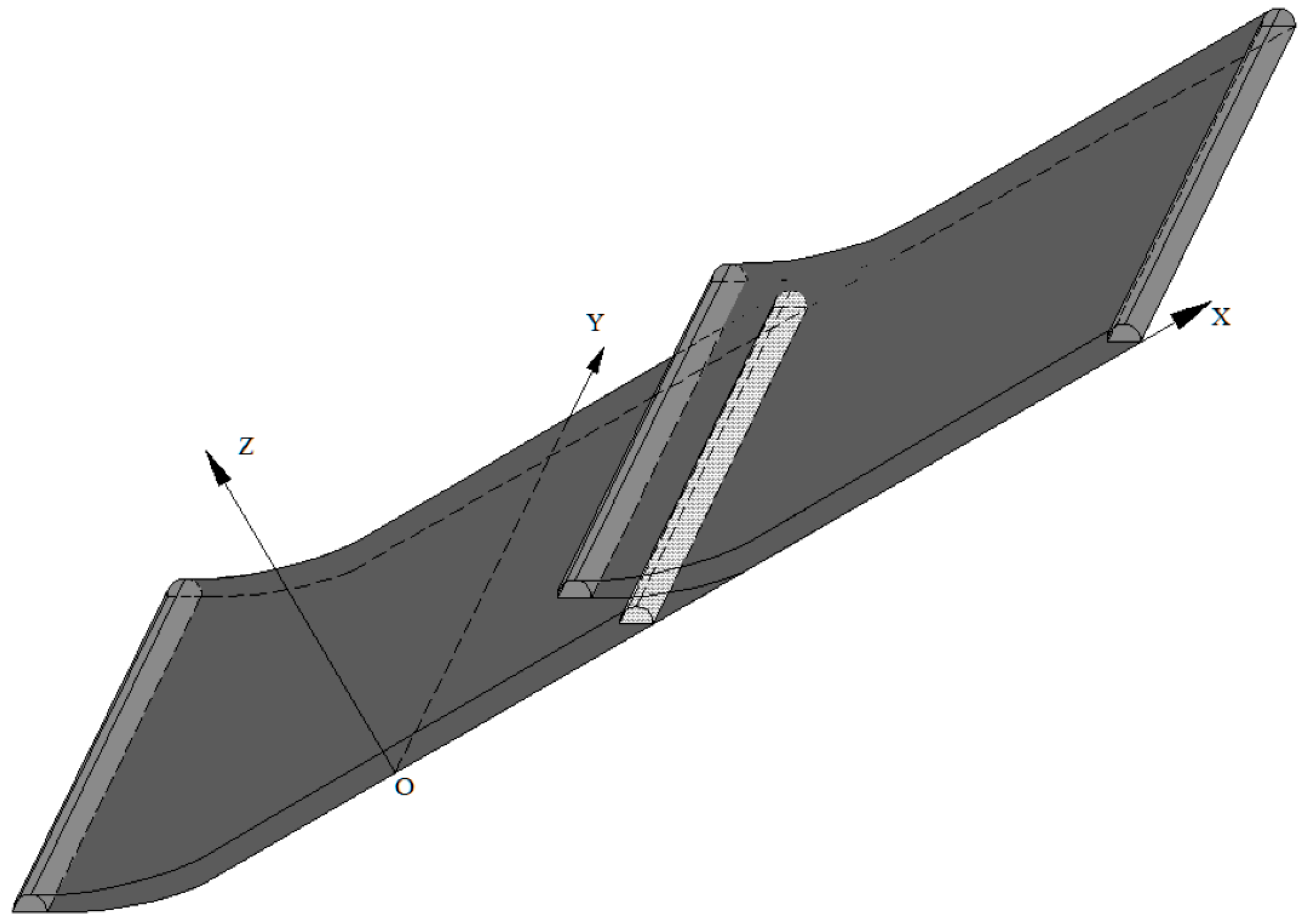
Gateways on either end of the No. Y294 panel in Tangshan coal mine are located at different heights within the coal seam. Its unique feature is a novel mining system which extends conventional mining system into three dimension as shown in Figure 15. Both theoretical study and practice show that LMSG is an effective way to enhance overall stability of mining equipment in working face in inclined coal seams; avoid or reduce stress concentration for development entry adjacent to the new panel which is located in the de-stressed zone with associated reduction in coal bumps, bursts and support problems; reduce the hazard of fire and spontaneous combustion, etc.
Nowadays, the depth of coal and other mineral mines, such as trona, that can be longwall-mined all over the world is increasing fast, how to avoid stress concentration at depth is urgent. LMSG is a preferable approach to achieve high-production and high efficiency in many difficult situations including at depth and in inclined seams, etc. LMSG stimulates researchers, engineers, etc., to conceive new ideas for panel layouts and pillar designs for the underground coal mine.
Coal mines currently using LMSG in China are all single-entry or two-entry systems which does not meet the demand in many other countries, such as U.S. Therefore, additional research, field pilot systems or technical and economical feasibility studies should be done to assess the performance of a multi-entry (three-, four-, five-, or more entry) LMSG system.
Acknowledgments
Financial support for this research provided by the Fundamental Research Funds for the Central Universities (No. 2011YZ10) and China Scholarship Council (No. 201506430011) are gratefully acknowledged.
Author Contributions
Jingli Zhao and Pengfei Wang conceived the main idea of the paper; All authors were involved in designing and carrying out the physical modelling experiment. Pengfei Wang wrote the paper. Yue Su did a lot of work to modify figures and proofread the revised version.
Conflicts of Interest
The authors declare no conflict of interest.
References
- Zhao, J.L. New Discussion on Whole Coal Seam Mining Techniques; China Coal Industry Publishing House: Beijing, China, 2004. (In Chinese) [Google Scholar]
- Du, J.P.; Meng, X.R. Mining Technology; University of Mining and Technology Press: Xuzhou, China, 2009. (In Chinese) [Google Scholar]
- Wu, Y.P.; Yun, D.F.; Zhang, M.F. Study on the elementary problems of fully mechanized coal mining in greater pitching seam. J. China Coal Soc. 2000, 25, 465–468. (In Chinese) [Google Scholar]
- Wu, Y.P.; Xie, P.S.; Yang, Y.G.; Ren, S.G. Numerical simulation and complexity analysis of strata movement in exploiting steep coal seams group. J. Min. Saf. Eng. 2007, 24, 391–395. (In Chinese) [Google Scholar]
- Kailuan Energy Chemical. Available online: http://www.kkcc.com.cn:8010/en/address.htm (accessed on 21 September 2016).
- Zhang, J.C. Practice of LMSG in thick coal seams. Inn. Mong. Coal Econ. 2014, 12, 108–161. (In Chinese) [Google Scholar]
- Zhao, J.L. Whole Seam Longwall Mining with Split-Level Gateways (LMSG) In Thick Coal Seams. China Patent ZL98100544.6, 23 January 2002. [Google Scholar]
- Zhao, J.L.; Li, B. A study on raising the recovery ratio of fully-mechanized coal-talking about stagger-position-roadway-arrangement system. J. Liaoning Tech. Univ. (Nat. Sci.) 1998, 17, 237–239. (In Chinese) [Google Scholar]
- Zhao, J.L. Triple Sections Mining Technology (TSMT) in LMSG in Thick Coal Seams. China Patent 2004100395750, 10 February 2004. [Google Scholar]
- Zhao, J.L. Study on whole seam longwall mining with split-level gateroad. J. China Coal Soc. 2004, 2, 142–145. (In Chinese) [Google Scholar]
- Zhao, J.L. “3-Section” Technology of Full-Dimension Mining in Flat Thick-Seam. J. China Univ. Min. Technol. 2004, 14, 13–15. [Google Scholar]
- Peng, S.S. Longwall Mining, 2nd ed.; Society for Mining, Metallurgy, and Exploration, Inc. (SME): Englewood, CO, USA, 2006. [Google Scholar]
- Zhao, J.L. Development and outlook of 3-D stagger arrangement roadway layout technology. Coal Eng. 2014, 46, 1–3. (In Chinese) [Google Scholar]
- Qian, M.G.; Shi, P.W.; Xu, J.L. Ground Pressure and Strata Control; China University of Mining and Technology Press: Beijing, China, 2010. (In Chinese) [Google Scholar]
- Qiao, J. Julia Sets and Complex Singularities of Free Energies; Memoirs of the American Mathematical Society: Providence, RI, USA, 2015; Volume 234, p. 1. Available online: http://www.ams.org/books/memo/1102/ (accessed on 28 July 2014).
- Ghabraie, B.; Ren, G.; Zhang, X.Y.; Smith, J. Physical modelling of subsidence from sequential extraction of partially overlapping longwall panels and study of substrata movement characteristics. Int. J. Coal Geol. 2015, 140, 71–83. [Google Scholar] [CrossRef]
- Zhu, W.S.; Li, Y.; Li, S.C.; Wang, S.G.; Zhang, Q.B. Quasi-three-dimensional physical model tests on a cavern complex under high in-situ stresses. Int. J. Rock Mech. Min. Sci. 2011, 48, 199–209. [Google Scholar]
Figure 1.
Conventional longwall mining system for Tangshan coal mine. (a) Plan view; (b) A-A section view of MLM (multi-slice longwall mining); (c) CLTCC (conventional longwall top coal caving).
Figure 1.
Conventional longwall mining system for Tangshan coal mine. (a) Plan view; (b) A-A section view of MLM (multi-slice longwall mining); (c) CLTCC (conventional longwall top coal caving).


Figure 2.
Longwall Mining with Split-level Gateways (LMSG). (a) LMSG for two adjacent panels; (b) Three-dimensional view of a LMSG panel.
Figure 2.
Longwall Mining with Split-level Gateways (LMSG). (a) LMSG for two adjacent panels; (b) Three-dimensional view of a LMSG panel.
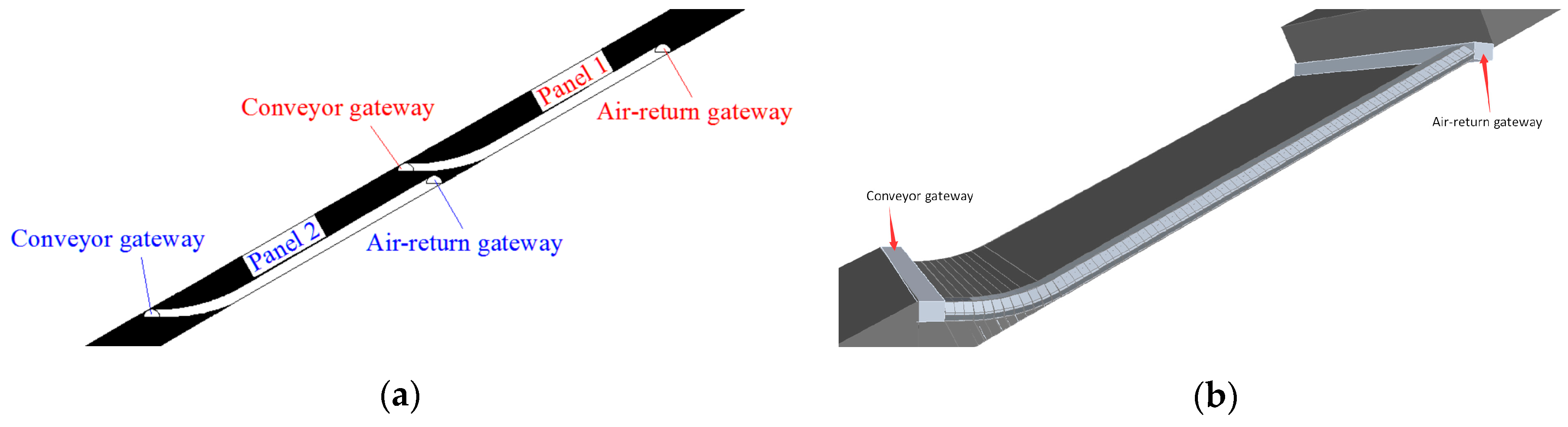
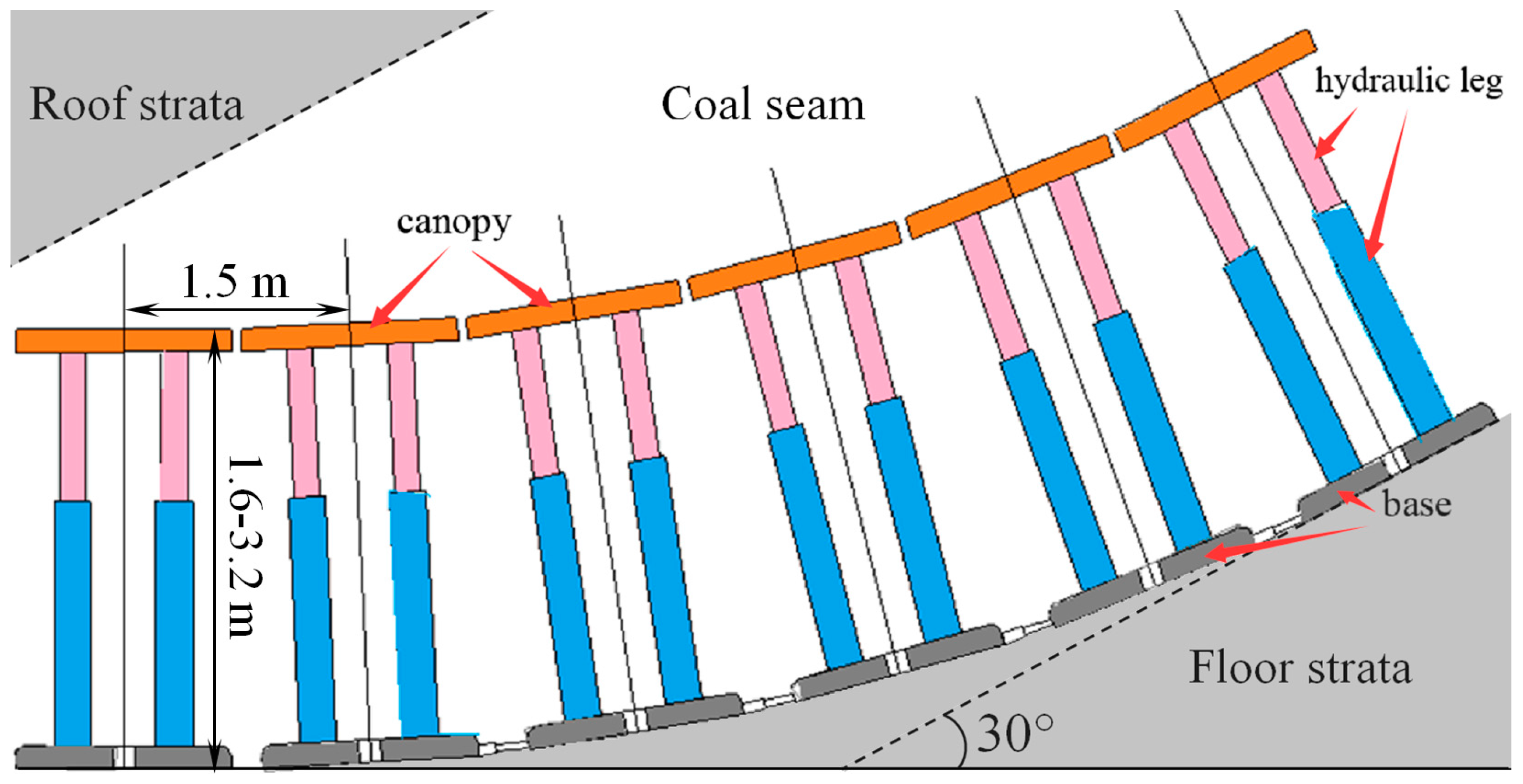
Figure 3.
Shield adjustment in an incline-to-flat polygonal-line transitional section.

Figure 4.
Triple sections mining technology (TSMT) of LMSG.

Figure 5.
Supplementary field measures employed to increase stability in Tangshan coal mine.

Figure 6.
Panel continuance plans for three panels. (a) Plan view; (b) A-A section view.

Figure 7.
Recovery ratio comparison of the two methods. (a) Coal loss in CLTCC and (b) coal loss in LMSG.
Figure 7.
Recovery ratio comparison of the two methods. (a) Coal loss in CLTCC and (b) coal loss in LMSG.

Figure 8.
Artificial roof support in the air-return gateway and caved rocks right behind the face end shields.
Figure 8.
Artificial roof support in the air-return gateway and caved rocks right behind the face end shields.

Figure 9.
Configuration of the overlapped part and stress distribution in LMSG.

Figure 10.
Spontaneous combustion-prone areas in CLTCC.

Figure 11.
Longwall equipment situation at the connection of the face to the gateway. (a) Conventional layout and (b) LMSG layout.
Figure 11.
Longwall equipment situation at the connection of the face to the gateway. (a) Conventional layout and (b) LMSG layout.

Figure 12.
LMSG for thin coal seams.
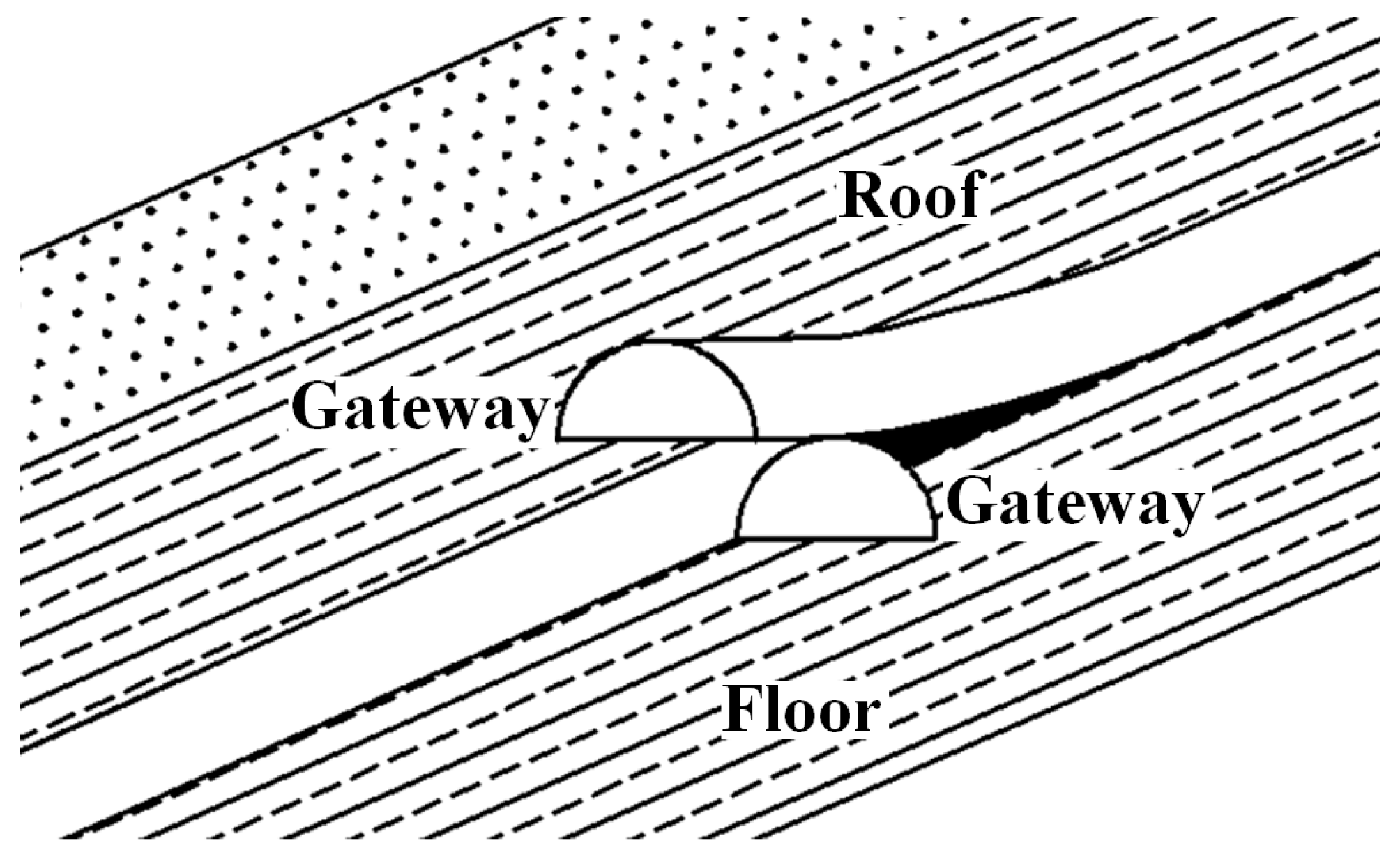
Figure 13.
LMSG in cases of accumulated water or large gas content within gob.

Figure 14.
Physical modelling and stress distribution results. (a) Physical model; (b) sensors and digital data acquisition system; (c) CLTCC layout; (d) LMSG layout; (e) excavation of the previous CLTCC panel; (f) excavation of the previous LMSG panel; (g) excavation of the Y294 CLTCC panel; (h) excavation of the Y294 LMSG panel; (i) excavation of the next CLTCC panel; (j) excavation of the next LMSG panel.


Figure 15.
Sketch of a three-dimensional concept of the LMSG system.


| Lithology | Number | Height/m | Character Description |
|---|---|---|---|
| Medium grained sandstone | 1 | 9.8 | Dark gray, argillaceous texture, plenty of plant root fossils |
| Siltstone | 2 | 5.7 | Dark gray, mainly quartz and feldspar |
| Coal No. 5 | 3 | 3 | Simple structure. |
| Siltstone | 4 | 11 | Dark gray, argillaceous texture, horizontal bedding planes |
| Coal No. 6 | 5 | 1.4 | With pyrite concretion |
| Sandy mudstone | 6 | 5.7 | Dark gray, with plant root fossil at the top and siderite concretion at the bottom |
| Coal No. 7 | 7 | 0.34 | Unstable, locally tailing-out |
| Siltstone | 8 | 4.2 | Dark gray, compact, with siderite concretion and plant root fossils |
| Medium grained sandstone | 9 | 4.9 | Light gray, mainly quartz, partially detritus, siliceous cemented, partially clipping with thin sandstone bed, horizontally stratified beddings |
| Siltstone | 10 | 7.5 | Dark gray, homogeneous, compact, horizontal stratification. |
| Carbon mudstone | 11 | 0–2.3 | Black, mainly carbonaceous content, with 1–2 coal lines |
| Coal Nos. 8 and 9 | 12 | 8.7 | Mainly dark bright coal, semi bright coal, vitreous and shiny, simple and hard. There are 1–2 layers of 0.5 m of gangue of black carbonaceous mudstone in the coal seam. |
| Siltstone | 13 | 3.15 | Dark gray, compact, Homogeneous, fine, with small amount of plant root fossils, calcite vein and scattered siderite crystals are seen |
| Fine grained sandstone | 14 | 3.29 | Brown and grey, mainly quartz, partially dead color minerals and small amount of detritus with calcium locally, relatively hard |
| Siltstone | 15 | 4.75 | Dark gray, homogeneous, fine and relatively pure, with shell-shaped fractures. |
| Method | Panel Width Lp (m) | Coal Seam Thickness Hc (m) | Height of the Gateway Hg (m) | Width of the Coal Pillar Lc (m) | Recovery Ratio η |
|---|---|---|---|---|---|
| CLTCC | 90 | 8.7 | 3 | 20 | 74.7% |
| LMSG | 102 | 8.7 | 3 | −5 | 89.1% |
| Lithology | Height (m) | Density (kg/m3) | Modulus of Elasticity (MPa) | Poisson’s Ratio | Internal Friction Angle (°) | Tensile Strength (MPa) | Cohesion (MPa) | UCS (MPa) |
|---|---|---|---|---|---|---|---|---|
| Siltstone | 11.0 | 2650 | 18,000 | 0.24 | 35 | 7.0 | 5.2 | 127 |
| Coal No. 6 | 1.4 | 1500 | 3000 | 0.25 | 25 | 1.2 | 0.8 | 19.7 |
| Sandy mudstone | 5.7 | 2600 | 15,000 | 0.24 | 34 | 6.0 | 6.1 | 96.0 |
| Siltstone | 4.2 | 2700 | 18,000 | 0.24 | 35 | 7.0 | 5.2 | 127 |
| Medium grained sandstone | 4.9 | 2600 | 32,000 | 0.22 | 40 | 7.3 | 6.4 | 144 |
| Siltstone | 8.0 | 2700 | 18,000 | 0.24 | 35 | 7.0 | 5.2 | 127 |
| Coal Nos. 8 and 9 | 8.7 | 1500 | 3000 | 0.25 | 25 | 1.2 | 0.8 | 19.7 |
| Siltstone | 3.2 | 2700 | 18,000 | 0.24 | 35 | 7.0 | 5.2 | 127 |
| Fine grained sandstone | 3.3 | 2650 | 20,000 | 0.23 | 37 | 7.3 | 4.8 | 99.0 |
| Rock Types | UCS (MPa) | Unit Weight (g/cm3) | Proportion Number | Materials | Aggregate:Materials | Lime:Plaster (lime:soil) |
|---|---|---|---|---|---|---|
| Medium grained sandstone | 0.062 | 1.625 | 6:5:5 | Fine sand:lime:plaster | 6:1 | 7:5 |
| Fine grained sandstone | 0.043 | 1.656 | 8:6:4 | Fine sand:lime:plaster | 7:1 | 6:4 |
| Siltstone | 0.055 | 1.688 | 6:5:5 | Fine sand:lime:plaster | 6:1 | 5:5 |
| Sandy mudstone | 0.042 | 1.625 | 10:9:1 | Fine sand:lime:plaster | 8:1 | 9:1 |
| Coal | 0.0085 | 0.938 | 10:1:0 | Fine sand:lime:soil | 10:1 | 7:2 |
© 2017 by the authors; licensee MDPI, Basel, Switzerland. This article is an open access article distributed under the terms and conditions of the Creative Commons Attribution (CC BY) license (http://creativecommons.org/licenses/by/4.0/).
Share and Cite
MDPI and ACS Style
Zhao, J.; Wang, P.; Su, Y. An Innovative Longwall Mining Technology in Tangshan Coal Mine, China. Minerals 2017, 7, 14. https://doi.org/10.3390/min7010014
AMA Style
Zhao J, Wang P, Su Y. An Innovative Longwall Mining Technology in Tangshan Coal Mine, China. Minerals. 2017; 7(1):14. https://doi.org/10.3390/min7010014
Chicago/Turabian StyleZhao, Jingli, Pengfei Wang, and Yue Su. 2017. "An Innovative Longwall Mining Technology in Tangshan Coal Mine, China" Minerals 7, no. 1: 14. https://doi.org/10.3390/min7010014
Note that from the first issue of 2016, this journal uses article numbers instead of page numbers. See further details here.