Technical Note

Beneficiation of a Sedimentary Phosphate Ore by a Combination of Spiral Gravity and Direct-Reverse Flotation

1
College of Resource and Environmental Engineering, Wuhan University of Science and Technology, Wuhan 430081, China
2
Hubei Collaborative Innovation Center for High Efficient Utilization of Vanadium Resources, Wuhan 430081, China
3
Hubei Provincial Engineering Technology Research Center of High efficient Cleaning Utilization for Shale Vanadium Resource, Wuhan 430081, China
*
Author to whom correspondence should be addressed.
Minerals 2016, 6(2), 38; https://doi.org/10.3390/min6020038
Submission received: 1 February 2016 / Revised: 29 March 2016 / Accepted: 13 April 2016 / Published: 20 April 2016

Abstract

:
In China, direct-reverse flotation is proved to be applicable to most phosphate ores. However, because the ratio of froth product is generally high, current direct-reverse technology faces challenges in terms of high reagent consumptions and cost. A new gravity and flotation combined process has been developed for the recovery of collophanite from sedimentary phosphate ore from the beneficiation plant of Hubei, China. In this process, 53% of the collophanite was firstly recovered by gravity separation, reducing the mass flow to direct flotation. The gravity tailing was the feed for the direct flotation. The flotation concentrate, mixed with gravity concentrate, was then subjected to reverse flotation. A final concentrate with a grade of 30.41% P2O5 at a recovery of 91.5% was produced from the feed analyzing 21.55% P2O5. Compared to the conventional direct-reverse flotation 86.1% recovery at 31.69% P2O5, it was found that pre-recovery of collophanite by spiral separation could significantly reduce the flotation reagent consumption and lead to improved overall collophanite recovery. The benefits of the new process in terms of cost savings were also discussed.

1. Introduction

Phosphate rocks are vital non-renewable resources and are essential components in fertilizer production. There is increasing demand for phosphate rock for fertilizers, animal feed stocks, food-grade phosphates, and other industrial uses [1,2,3]. About 95% of the phosphate produced around the world is consumed in the fertilizer industry [4,5]. China has about 20 billion tonnes of abundant phosphate ore reserves (including reserve base) ranking it second in the world [6]. The phosphate ores in China can be classified as igneous rock, metasedimentary, and sedimentary, and each are significantly different in their flotation characteristics. The igneous apatite ores and metasedimentary phosphate rocks have relatively good floatability. However, these reserves are rapidly being depleted, prompting the development of recovery methods for the more abundant sedimentary ores [4,7]. The sedimentary ores contain apatite with a very small grain size, typically micro- to optically-visible, which can be highly intergrown with gangue materials and are, thus, called cryptocrystal, or classified as “colloidal phosphate ore” (collophanite) in China. This implies that the sedimentary ores are difficult to float and require fine grinding.
Phosphate ore processing techniques are dependent on the type of phosphate minerals and associate gangue. To meet the requirement of fertilizer industry, phosphate ore should be enriched to near 30% P2O5 [8]. Flotation has been used in industry for more than half century as the primary technique for upgrading phosphate. More than 60% of the commercial phosphate in the world is produced by flotation [9]. The flotation process not only upgrading the P2O5 grade but also reducing the particle size to 100 mesh content more than 90% [10]. The present techniques used in flotation of the sedimentary phosphate ore are generally classified into three categories: (i) direct-reverse flotation (or reverse-direct flotation); (ii) single-reverse flotation, and (iii) double-reverse flotation [2,11,12]. The direct-reverse method is more attractive, as it has been proved to be applicable to most phosphate ores in China [7]. In this process, the siliceous minerals are discharged by direct flotation while the calcareous minerals are discharged by reverse flotation. Although the direct-reverse process has been improved with the use of more efficient collectors, reagent consumption has also increased significantly. Therefore, there is an imperative to improve this process or develop alternate processing methods.
Gravity separation is an important unit process due to its advantages of easy manipulation and low cost. Some research on the application of gravity separation for sedimentary phosphate ore has been conducted. Yang [13] investigated a gravity-flotation process. The results showed that shaking table gravity separation could reduce ore mass flow to the flotation process. However, this combined process had high capital and operating costs. Attrition scrubbing techniques have been successfully used to upgrade some mid-grade, weathered, sedimentary phosphate ores in the Yunnan province, China [14]. This technique was used when the main gangue minerals were clays. However, with a decline of the ore grade and an increase of the content of impurities, attrition scrubbing processes have gradually lost their place. Another successfully commercialized gravity technique is the heavy medium cyclone process, used for discharging coarse dolomite at Yihua Group, Hubei province, China [14,15]. The gravity concentrate was then subjected to double-reverse flotation for further discharging of dolomite. However, it has been shown to not be suitable for processing fine particles.
Among various kinds of gravity separators, the spiral concentrator is considered to be one of the most efficient and simple operation units. Since their fully commercial use in the early 1940s, spirals have proved to be a cost-effective and efficient method for concentrating a variety of ores [16,17]. In recent years, fine mineral spiral separators have been successfully used for processing ever-finer materials [18,19,20]. Due to the low settling velocities of very fine mineral particles, smaller bed depths and laminar flows are required for efficient separation [18]. Accordingly, a fine mineral spiral separator has a significantly smaller ratio of pitch to diameter (P/D) than the traditional spirals [21]. However, there is little information on recovery of apatite or collophanite from ultra-fine phosphate ore by fine spiral separators.
The objective of this work was to investigate a simple gravity process for the possible pre-recovery of collophanite from direct flotation allowing a reduction in reagent consumptions. The gravity concentrator used was a fine mineral spiral, with a P/D ratio of only 0.36. The study focused on the reagent consumptions of two different flowsheets, the conventional direct-reverse flotation process and the gravity-flotation combined process. A new gravity-flotation combined process was proposed and tested, which significantly reduced the cost for producing 1 t of concentrate.

2. Materials and Methods

2.1. Materials

The sedimentary phosphate ore sample used in this work was collected from Yihua Group Co., Ltd., Yichang, China. The results of chemical composition analysis and mineral composition are shown in Table 1 and Table 2. Around 200 kg of representative ore samples was crushed to below 3 mm with a two-stage jaw crusher and a one-stage roll crusher. The materials were then well mixed and divided into 1 kg samples for separation studies. The chemical analysis was performed with the Xios advanced X-ray fluorescence (XRF) analyzer, the results are tabulated in Table 1.
Optical microscopy and X-ray diffraction (XRD) studies were performed to define the main minerals and their interlocking characteristics. The results of optical mineralogy are showed in 
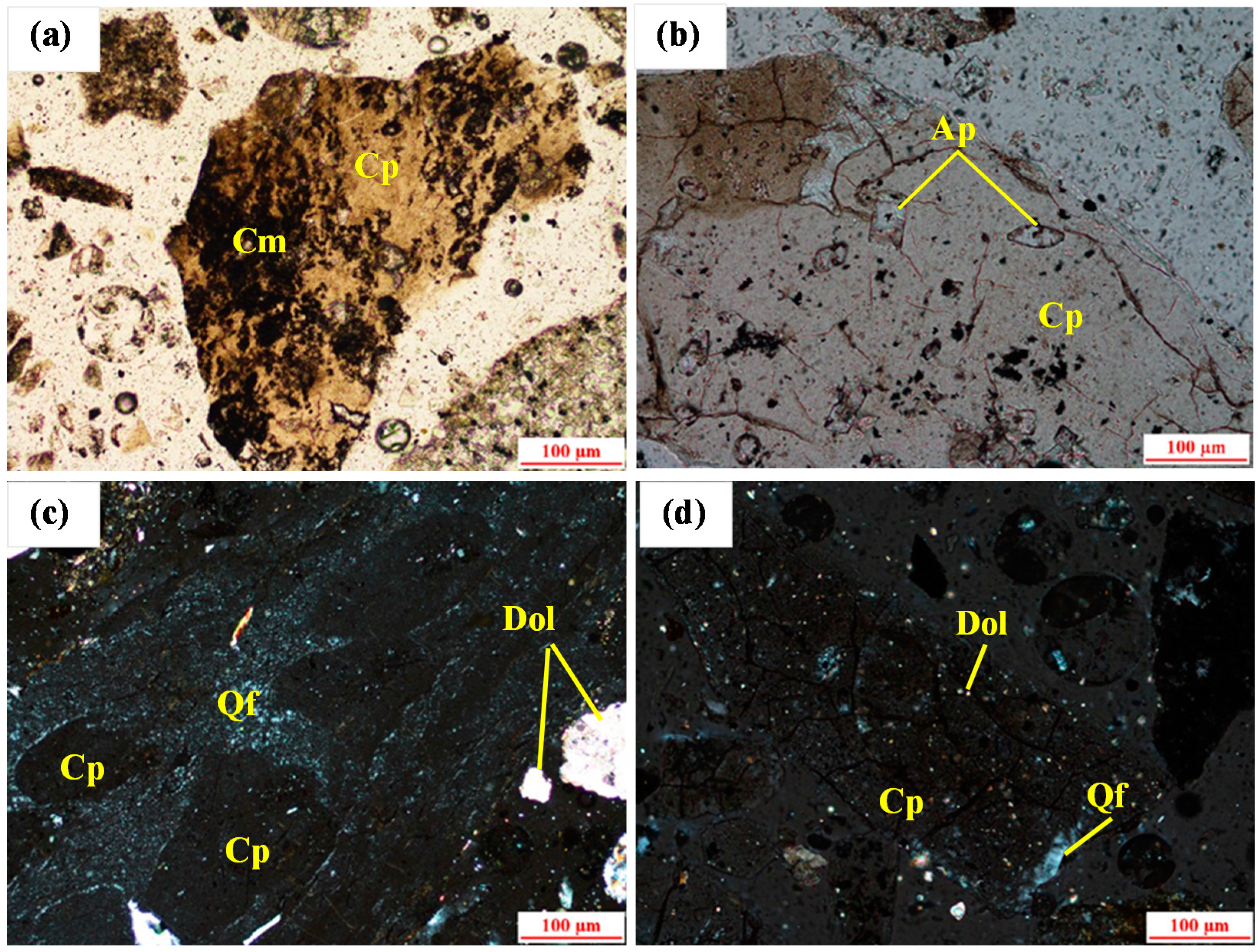
Figure 1. Collophanite grains are polygonal, plate-like, and are usually between 0.05 and 0.8 mm. Small apatite grains (0.01–0.05 mm) could be found in some collophanite grains (Figure 1b). Some of the gangue minerals are occurs as endogangue in the collophanite grains as shown in Figure 1a,c,d. The majority of gangue minerals are appear between the collophanite grains. These gangue minerals are clay minerals, the aggregate of quartz, feldspar, and dolomite. The grains of quartz and feldspar are small and difficult to distinguish between them. Their aggregate is between 0.03 and 0.1 mm, and is usually in the exogangue (Figure 1d) and sporadically distributed in the collophanite grains (Figure 1c). It can be seen from Figure 1c that the dolomite minerals are hypidiomorphic granular structure, scattered, and grains size are usually between 0.03 and 0.1 mm. Dolomite as exogangue (Figure 1c) and endogangue (Figure 1d) exist between and in the collophanite grains. Clay mineral pellets are mainly composed of illite, kaolinite. They usually appear in the form of crystal stock, either or as endogangue in collophanite grains (
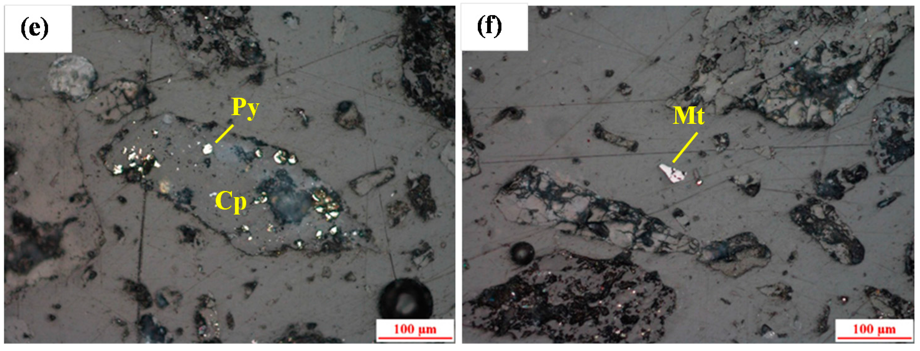
Figure 1a). In addition to this, there are slight iron minerals like pyrite (Figure 1e), magnetite (Figure 1f) and hematite created small grains (0.01–0.03 mm) which sporadically distribute in collophanite grains, quartz and feldspar aggregates, and clay minerals aggregates.
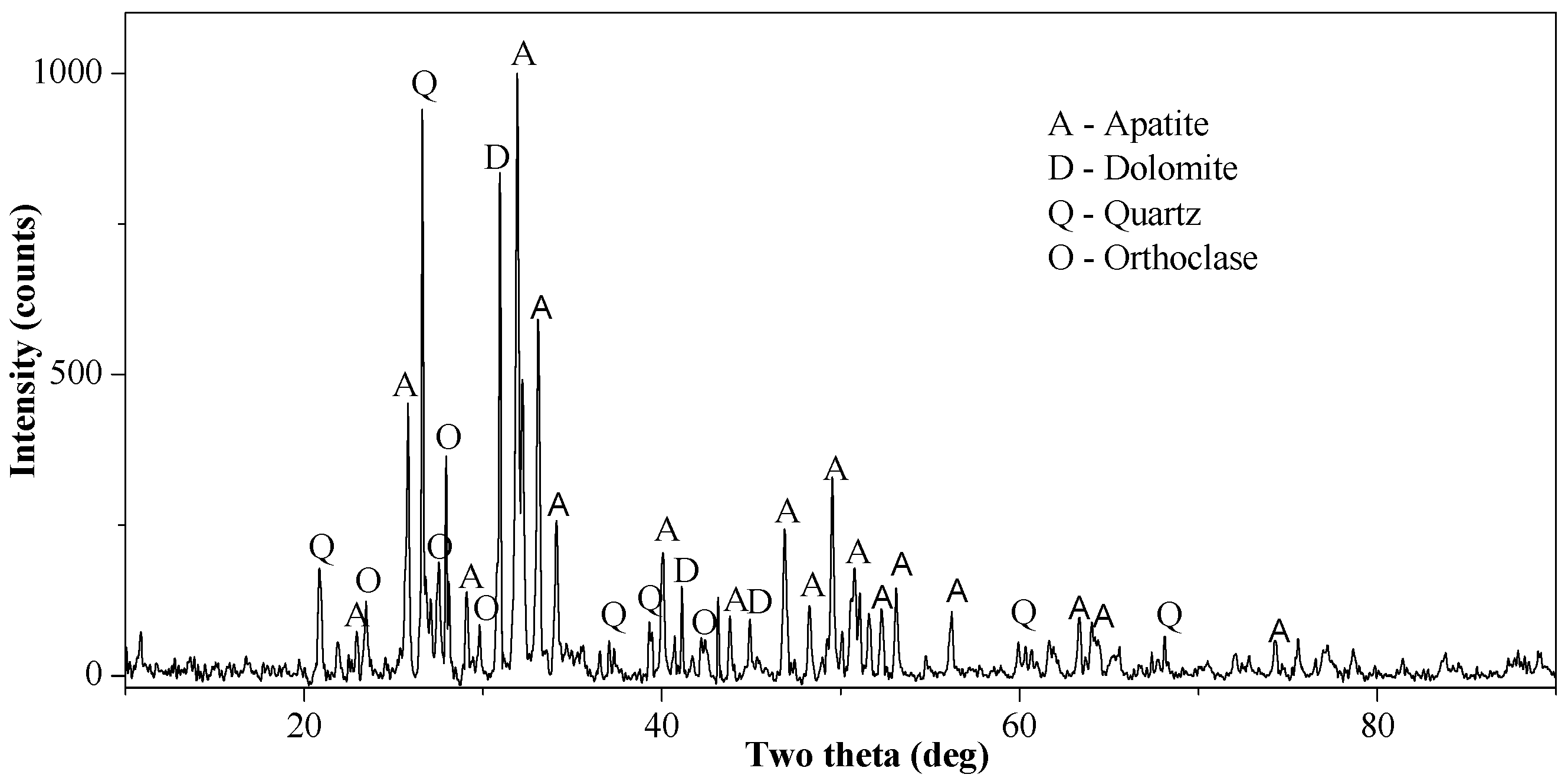
The results of optical mineralogy and the XRD analysis (Figure 2) revealed the major phases of minerals which to be apatite, quartz, dolomite, clay minerals, and pyrite. The mineral composition of the sample was obtained by the comprehensive analysis of the chemical composition, optical microscopy and XRD. The results are shown in Table 2. The density of the main minerals is also tabulated in Table 2 [22].
The samples were firstly wet ground in a HLXMQ-Φ240 × 90 laboratory ball mill from Wuhan Exploring Machinery Factory (Wuhan, China) at 50 wt % solids, until a particle size distribution of 70% passing 74 μm was achieved. The ground product was then subjected to characterization studies and separation studies. The particle size fraction analysis which was carried out using a Mastersizer 2000 laser particle characterization system (Malvern Instruments Ltd., Malvern, UK), showing that the specific surface of the ground product was 0.78 m2/g, and the d10, d50, and d90 (diameter at the cumulative undersize of 10%, 50%, and 90%) was 2, 51 and 115 μm, respectively. The liberation of collophanite was analyzed. To start with, a representative sample of particles weighing approximately 5 g was taken from +30 μm size fractions of the ground product. The −30 μm latter size fraction was not prepared for liberation analysis in a reflecting microscope, due to magnification restrictions, which makes it difficult to definitely distinguish mineral particles. The results showed that the liberation degree in +30 μm is 70.4%. The viscosity of slurry was measured by NDJ-5S viscometer (Hengping Scientific Instruments Ltd., Shanghai, China). The results showed that, while the solid content between 10% and 35%, the viscosity increased slowly from 1.168 to 1.176 mPa·s as the solid content increased. Surface tension measurement was conducted by the Du Noüy ring method. The results showed that the surface tension of the slurry was 63 mN/m at reverse flotation conditions, while 54 mN/m at direct flotation conditions.
Commercial water glass (WG) from Xiangxing Co. Ltd. (Loudi, China) of modulus 3.1 was used as the depressant for silicate minerals and dispersant, which had a purity of 97%. Na2CO3 from Xilong Chemical Co., Ltd. (Wuhan, China) with purity of 99% was used as a pH modifier in direct flotation. Sulfuric acid (SA) from Pingmei Group Co. Ltd. (Pingdingshan, China) was used as a pH modifier (98% purity) in reverse flotation. Commercial product CXY-P (a fatty acid mixture) from Chuxiang Phosphorus Technology Ltd. (Wuhan, China) was used as a collector.
The water used was the potable water in Wuhan, China.

2.2. Methods

The process with the gravity and the flotation was termed as the “new process”. The diagram of the actual process which was applied during 2014 is shown in Figure 3a. The diagram of the conventional direct-reverse flotation configuration is shown in Figure 3b. Spiral separation was used to improve the economics of the process and the new combined process is illustrated in Figure 3c.

2.2.1. Gravity Separation Tests

The gravity tests are comprised classification and spiral separation. In order to avoid the negative effects of coarse particles on the spiral separation, classification was firstly used for recovery of +150 μm size fraction particles from the feed. Then spiral separation was carried out. The separator used for the tests was a five-turn laboratory spiral. The design data of the spiral are given in Table 3 and the set-up used for the experiments is shown in Figure 4. A manual valve combined with a rotameter was used to adjust the flow of wash water for the spiral. The wash water was only supplied when sampling. Batch experiments were conducted to investigate different influences; solid content, feed rate, and wash water.

2.2.2. Flotation Tests

Flotation tests were carried out using a XFDIV (equipment model) single flotation machine from Jilin Provincial Machine Factory of Ore Exploration (Changchun, China). The impeller speed was 1750 rpm and flotation was conducted at a pulp temperature of 25 °C. A 1.0 L flotation cell was prepared for the direct flotation tests, and a 0.75 L flotation cell for the reverse flotation. For each direct flotation test, the pulp containing 330 g of feed ore was transferred into the flotation cell and stirred for 1 min. Sodium carbonate was added into the pulp to achieve a pH at 10 with 2 min of conditioning time. Then WG was added, and conditioned for another 2 min. Next, the collector CXY-P was added and the slurry was stirred for 2 min. All conditioning processes were conducted in the absence of airflow. For each reverse flotation test, the feed was the concentrate from ether the gravity or the direct flotation. SA was firstly added to achieve a pH at 4.5 with 0.5 min conditioning time. CXY-P was added and conditioned for 2 min before flotation. Batch experiments were conducted to find the optimal dosages of reagents by single factor test method, and using the parallel test to increase the stability. The optimal flotation conditions are shown in Figure 5.

3. Results

3.1. Gravity Separation Results

The results of particle size analyses of the feed (Table 4) showed that the P2O5 grade of +150 μm in the feed was more than 26%. It could be collected as a separate concentrate by classification. In the spiral separation process, the spiral feed (−150 μm of the feed) was separated into seven streams, numbered from 1 to 7. The width of every stream was 24 mm. A cross-section of the spiral trough flow is shown in Figure 6 and illustrates the separation process. Optimized test conditions showed a pulp density of 18 wt % solids, a wash water flow rate of 30 L/h, and a feed rate of 150 L/h.
Figure 7 shows that as the product number increased, P2O5 content decreased sharply down to number 4, then it slowly increased above that. Meanwhile, SiO2, Al2O3, and MgO contents were concentrated in light products (high product number).
Figure 8 illustrates the P2O5 cumulative grade vs. product number curve. When the product number increased above 2, the P2O5 cumulative grade decreased significantly. This data suggest that the concentrate splitter position at product number 2 could achieve higher selectivity between collophanite and gangue minerals.
The separation results (Table 5) also indicated that the collophanite particles were concentrated in the high density products (heavies) and gangue particles separated to low density streams. It can be observed that the heavies of the spirals were enriched to 28.22% P2O5 with a distribution of 52.8% in 40.3% of the weight.

3.2. Flotation Tests Results

Table 6 shows the results of the flotation tests. A concentrate of 30.56% P2O5 was produced at a P2O5 recovery of 86.3% by the new process. With a given P2O5 recovery rate (86%), the new process produced a concentrate with a slight little lower P2O5 grade (30.56%) than the conventional process (31.69%).

3.3. Flowsheet Test Results

The flowsheet for combined gravity-flotation (Figure 9) shows that the P2O5 grade of the final concentrate was 30.41%, while the P2O5 recovery was 91.5%. In this process, 1.8% and 51.0% collophanite were pre-collected by gravity separation using classification and spiral separators, respectively. The lights from spiral separation was then subjected to direct flotation. The mixed concentrate from the gravity-direct flotation was subjected to reverse flotation. Combined with the XRE analysis (Figure 2) and the XRF analysis (Figure 10) of concentrates and raw ore, it is showed that Al primarily originated from clay mineral. Compared to the conventional process, the new process produced a concentrate with a slight little lower Al2O3 content. It is indicated that the new process can improve the efficiency of discarding clay minerals.
In the actual process, which was applied during 2014, beneficiation recovery is about 69% at reagent costs of 14.6 CNY/1 t of concentrate and raw ore cost of 209 CNY. A comparison of the costs in the actual process, the conventional process and the new process was made. The results are shown in Figure 11. Compared to the actual process, in the new process, the raw ore cost for producing 1 t of concentrate decreases by 38.8 CNY. However, the reagent costs only increase 7.5 CNY/1 t of concentrate. The net benefit is 31.3 CNY/1 t of concentrate and boosts the profits by 39%, whilst the conventional process costs more than the actual process.

4. Conclusions

  • The results of this study showed that the fine spiral of a 0.36 P/D ratio was an useful separator for pre-recovery of collophanite from Yichang ultra-fine sedimentary phosphate ore. A final concentrate with a grade of 30.41% P2O5 and a recovery of 91.5% can be produced by a combined process of gravity and direct-reverse flotation.
  • Compared to the actual process applied during the year 2014, the use of gravity concentrator in the flowsheet achieved significant cost savings. The net benefit is 31.3 CNY/1 t concentrate and boosts the profits by 39%, whilst the conventional process costs 10.8 CNY more than the actual process for producing 1 t of concentrate.

Acknowledgments

This work was financially supported by the Research Project of Hubei Province, China (No. 2014BCB029).

Author Contributions

Xin Liu and Yimin Zhang conceived and designed the experiments; Xin Liu performed the experiments; Xin Liu and Kun Sun analyzed the data; Tao Liu, Zhenlei Cai, and Tiejun Chen contributed reagents/materials/analysis tools; Xin Liu wrote the paper.

Conflicts of Interest

The authors declare no conflict of interest.

References

  1. Shariati, S.; Ramadi, A.; Salsani, A. Beneficiation of low-grade phosphate deposits by a combination of calcination and shaking tables: Southwest Iran. Minerals 2015, 5, 367–379. [Google Scholar] [CrossRef]
  2. Mohammadkhani, M.; Noaparast, M.; Shafaei, S.Z.; Amini, A.; Amini, E.; Abdollahi, H. Double reverse flotation of a very low grade sedimentary phosphate, rich in carbonate and silicate. Int. J. Miner. Process. 2011, 100, 157–165. [Google Scholar] [CrossRef]
  3. Guo, F.; Li, J. Separation strategies for Jordanian phosphate rock with siliceous and calcareous gangues. Int. J. Miner. Process. 2010, 97, 74–78. [Google Scholar] [CrossRef]
  4. Abouzeid, A.Z.M. Physical and thermal treatment of phosphate ores—An overview. Int. J. Miner. Process. 2008, 85, 59–84. [Google Scholar] [CrossRef]
  5. The United States Geological Survey (USGS). Mineral Information. Phosphate Rock. Available online: http://minerals.usgs.gov/minerals/pubs/commodity/phosphate_rock/ (accessed on 18 April 2016).
  6. Li, W.; Gao, H.; Luo, Y.; Gao, J. Status, trends and suggestions of phosphorus ore resources at home and abroad. China Min. Mag. 2015, 6, 6–10. (In Chinese) [Google Scholar]
  7. Wei, Y.; Wang, S.; Li, X.; Sandenbergh, R. Improvement of phosphate ore flotation performance through sized flotation. In Proceedings of the International Mineral Processing Congress (IMPC), Brisbane, Australia., 6–10 September 2010.
  8. Abouzeid, A.Z.M.; Negm, A.T.; Elgillani, D.A. Upgrading of calcareous phosphate ores by flotation: Effect of ore characteristics. Int. J. Miner. Process. 2009, 90, 81–89. [Google Scholar] [CrossRef]
  9. Cao, Q.; Cheng, J.; Wen, S.; Li, C.; Bai, S.; Liu, D. A mixed collector system for phosphate flotation. Miner. Eng. 2015, 78, 114–121. [Google Scholar] [CrossRef]
  10. Zhang, W.; Huang, J. Phosphatic Fertilizer; Chemical Industry Press of China: Beijing, China, 2005; pp. 92–94. (In Chinese) [Google Scholar]
  11. Boulos, T.R.; Yehia, A.; Ibrahim, S.S.; Yassin, K.E. A modification in the flotation process of a calcareous-siliceous phosphorite that might improve the process economics. Miner. Eng. 2014, 69, 97–101. [Google Scholar] [CrossRef]
  12. Ge, Y.; Gan, S.; Zeng, X.; Yu, Y. Double reverse flotation process of collophanite and regulation froth action. Trans. Nonferr. Metals Soc. China 2008, 18, 449–453. [Google Scholar] [CrossRef]
  13. Yang, M. Test on gravity-flotation complex process of mid-low grade phosphate rock in Dianchi region. Ind. Miner. Process. 2004, 5, 3–5. (In Chinese) [Google Scholar]
  14. Tan, M.; Wei, M. Progress in beneficiation of phosphorite ores. Min. Metall. 2010, 4, 1–6. (In Chinese) [Google Scholar]
  15. Le, H.; Shao, T. Promoting of heavy medium cyclone and new technology application. Coal Sci. Technol. 2008, 5, 5–9. [Google Scholar]
  16. Mishara, B.K.; Tripathy, A. A preliminary study of particle separation in spiral concentrators using DEM. Int. J. Miner. Process. 2010, 94, 192–195. [Google Scholar] [CrossRef]
  17. Das, S.K.; Godivalla, K.M.; Panda, L.; Bhattacharya, K.K.; Singh, R.; Mehrotra, S.P. Mathematical modeling of separation characteristics of coal-washing spiral. Int. J. Miner. Process. 2007, 84, 118–132. [Google Scholar] [CrossRef]
  18. Richards, R.G.; MacHunter, D.M.; Gates, P.J.; Palmer, M.K. Gravity separation of ultra-fine (−0.1 mm) minerals using spiral separators. Miner. Eng. 2000, 1, 65–77. [Google Scholar] [CrossRef]
  19. Liu, H.Z. Development of BL1500-A spiral chute and its application in tailings retreatment. Min. Metall. 2001, 4, 24–28. (In Chinese) [Google Scholar]
  20. Chen, T.J.; Zhang, Y.M. Experiments of acid pellet using treated pyrite slag and its commercial application. Res. Iron Steel 2005, 1, 1–4. [Google Scholar] [CrossRef]
  21. Kapur, P.C.; Meloy, T.P. Spirals observed. Int. J. Miner. Process. 1998, 53, 15–28. [Google Scholar] [CrossRef]
  22. Wu, L.; Bai, G.; Yuan, Z. Minerals and Rocks; Chemical Industry Press of China: Beijing, China, 2010; pp. 169–200. (In Chinese) [Google Scholar]
Figure 1. Optical microscopy images of raw ore observed with: (a) and (b) non-cross-polarized light; (c) and (d) cross-polarized light; (e) and (f) reflected light. (Cp: collophanite; Cm: clay minerals; Ap: apatite; Qf: Quartz and feldspar minerals aggregate; Dol: dolomite; Py: pyrite; Mt: magnetite.)
Minerals 06 00038 g001aMinerals 06 00038 g001b
Figure 2. X-ray diffraction (XRD) image of raw ore.
Minerals 06 00038 g002
Figure 3. (a) Diagram of the actual process (2014); (b) the conventional process and (c) the new gravity and flotation combined process.
Minerals 06 00038 g003
Figure 4. (a) Recirculating spiral and (b) its schematic set-up.
Minerals 06 00038 g004
Figure 5. The flotation flowsheet for the conventional process (a) and the new process (b).
Minerals 06 00038 g005
Figure 6. A sectional view of the spiral trough flow.
Minerals 06 00038 g006
Figure 7. Chemical compositions of the products from spiral separation.
Minerals 06 00038 g007
Figure 8. P2O5 cumulative grade curve.
Minerals 06 00038 g008
Figure 9. Flowsheet for the gravity-flotation process.
Minerals 06 00038 g009
Figure 10. Chemical compositions of concentrates and raw ore.
Minerals 06 00038 g010
Figure 11. Benefit of the new process and the conventional process, compared to the actual process (2014).
Minerals 06 00038 g011
Table 1. Chemical composition of raw ore.
ComponentP2O5SiO2Al2O3Fe2O3MgOCaO
%21.5425.284.562.302.2431.77
Table 2. Mineral composition of raw ore.
MineralCollophaniteQuartzClayDolomitePyriteOther
Content (%)52.516.314.110.32.04.8
Density (g/cm3)3.142.542.1–2.72.824.92-
Table 3. Physical structure parameters of the spiral.
HeightPitch (P)Outer Diameter (D)Inner RadiusRadial WidthTrough Slope Angle (θ)
850 mm144 mm400 mm16 mm184 mm
Table 4. Particle size and chemical analyses of the feed (Dist.: distribution).
Size Fraction (μm)wt %P2O5MgOAl2O3SiO2
%% Dist.%% Dist.%% Dist.%% Dist.
+1501.526.141.80.740.53.811.321.751.3
−150 + 7428.624.1231.81.3016.53.9024.624.3528.4
−74 + 4523.623.3925.52.3024.24.1821.822.2821.5
−45 + 387.722.007.82.889.84.347.3023.227.2
−38 + 256.120.545.83.299.04.666.3022.875.7
−2532.518.1827.32.7740.05.3838.626.9735.8
Feed100.021.67100.002.25100.04.53100.024.50100.0
Table 5. Results of the spiral separation (Rec.: recovery).
ProductsProduct No.wt %P2O5MgOAl2O3SiO2
%% Rec.%% Rec.%% Rec.%% Rec.
Heavies113.930.0719.31.8111.21.484.88.374.6
226.427.2533.52.0524.22.4515.214.8015.6
Total40.328.2252.81.9735.42.1220.012.5920.2
Lights322.617.3418.22.2022.25.4929.234.3430.9
45.314.533.52.445.76.447.939.508.3
53.416.722.62.603.95.664.533.644.5
69.017.437.32.5910.55.7012.131.4911.4
719.417.2015.52.5822.35.7826.332.1024.7
Total59.717.0347.22.4364.65.7180.033.5979.8
Feed100.021.54100.02.24100.04.26100.025.13100.0
Table 6. Open circuit flotation results for the conventional process and the new process.
ProcessProductwt %P2O5MgO
%% Rec.%% Rec.
ConventionalConcentrate58.8231.6986.050.7219.36
Carbonate9.165.602.3715.5064.93
Silicate25.584.285.050.839.70
Middling6.4421.946.532.046.01
Total10021.661002.21100
NewConcentrate60.8030.5686.280.7821.41
Carbonate8.445.912.3215.9360.53
Silicate21.333.783.740.959.11
Middling9.4317.487.662.118.95
Total10021.531002.22100

