Article

Scale Effect of Premixed Methane-Air Combustion in Confined Space Using LES Model

1
State Key Lab of Coal Mine Disaster Dynamics and Control, Chongqing University, Chongqing 404000, China
2
School of River and Ocean Engineering, Chongqing Jiaotong University, Chongqing 404000, China
3
Faculty of Engineering, Monash University, Melbourne, Victoria 3800, Australia
4
Mining and Nuclear Engineering Department, Missouri University of Science and Technology, Missouri, MO 65409, USA
*
Author to whom correspondence should be addressed.
Minerals 2016, 6(1), 2; https://doi.org/10.3390/min6010002
Submission received: 28 October 2015 / Revised: 3 December 2015 / Accepted: 14 December 2015 / Published: 29 December 2015
(This article belongs to the Special Issue Advanced Underground Mine Ventilation and Monitoring Systems)

Abstract

:
Gas explosion is the most hazardous incident occurring in underground airways. Computational Fluid Dynamics (CFD) techniques are sophisticated in simulating explosions in confined spaces; specifically, when testing large-scale gaseous explosions, such as methane explosions in underground mines. The dimensions of a confined space where explosions could occur vary significantly. Thus, the scale effect on explosion parameters is worth investigating. In this paper, the impact of scaling on explosion overpressures is investigated by employing two scaling factors: The Gas-fill Length Scaling Factor (FLSF) and the Hydraulic Diameter Scaling Factor (HDSF). The combinations of eight FLSFs and five HDSFs will cover a wide range of space dimensions where flammable gas could accumulate. Experiments were also conducted to evaluate the selected numerical models. The Large Eddy Simulation turbulence model was selected because it shows accuracy compared to the widely used Reynolds’ averaged models for the scenarios investigated in the experiments. Three major conclusions can be drawn: (1) The overpressure increases with both FLSF and HDSF within the deflagration regime; (2) In an explosion duct with a length to diameter ratio greater than 54, detonation is more likely to be triggered for a stoichiometric methane/air mixture; (3) Overpressure increases as an increment hydraulic diameter of a geometry within deflagration regime. A relative error of 7% is found when predicting blast peak overpressure for the base case compared to the experiment; a good agreement for the wave arrival time is also achieved.

1. Introduction

The most typical category of gaseous explosion accidents is methane explosion accidents in the mining industry. It normally leads to significant economic loss and a massive amount of casualties [1]. They can occur in unconfined spaces, such as combustion due to flammable gas leakage, as well as in confined spaces, such as inner-combustion in processing equipment and methane explosions in the airways of underground mines. Gaseous explosions in confined spaces are more intensive compared to unconfined spaces, provided that the total energy of the explosives is the same. In addition, explosion characteristics are also affected by the geometry of the selected confined space. The sizes of confined spaces, commonly encountered in processing and mining industries, could differ by as much as an order of four [2]. A better understanding of the scaling effect on gaseous explosions could contribute to explosion mitigation and prevent operation activities within high-risk regions. This research paper has investigated this scaling effect and its impact on explosion propagation. The approach to investigate explosions is either experimental or numerical. Large-scale explosion experiments are often costly and dangerous [3,4]. Lab-scale experiments and numerical methods are common alternatives. However, it is not yet clear if the findings in lab scale experiments can be used to represent explosion characteristics or not. On the other hand, Computational Fluid Dynamics (CFD) modeling has been used to simulate chemical combustions and, thus, can be used to evaluate the scaling effects in methane explosions.
Many efforts were made to investigate the scaling effect of methane and hydrogen explosions, numerically and experimentally. In van Wingerden’s work, the scaling effect is related to the normalized flame speed. However, this relationship stops when turbulence is incorporated in the analysis [5]. Catlin and Johnson [2,3] tried various possibilities to compensate the scaling effect by enriching the oxygen component in the air during their experiments. The results are theoretically reasonable when the turbulence Reynolds number is smaller than 10,000, which often is not the case for practical problems. Di Sarli’s team investigated gas explosion using the Large Eddy Simulation (LES) model for premixed turbulent combustion when considering the presence of obstacles, and assessed different sub-grid combustion models. They found out that large vortexes play a leading role in flame characteristics, and explained that the peak overpressure of a selected explosion is affected by combustion and venting rates; the combustion sub-model is sensitive to the flame-vortex interaction regime [6,7,8,9,10]. Zhang tested the scaling effect on a methane explosion using a CFD commercial package AutoReaGas in his study, where three scales (1:1, 1:10 and 1:100) were included. His findings show that: At a length to diameter ratio of less than 80, the peak overpressure does not yield the geometric similarity law [4,11]. Therefore, there is a need to further study the scaling effects on gaseous explosions, particularly for scenarios with lower longitudinal to horizontal ratios. This research provides a wide range of geometry models, and highlights the scaling effect on deflagration to detonation transformation (DDT) when a stoichiometric methane/air mixture is ignited. The Gas-fill Length Scaling Factor (FLSF) and Hydraulic Diameter Scaling Factor (HDSF) are employed to adjust the geometric models. FLSF and HDSF are used to enlarge or to shrink the dimensions of a selected geometric model, longitudinally and horizontally, in order to obtain a wide spectrum of its scales. In addition, a turbulent closure LES model is applied and compared to the widely used Reynolds averaged models. The capability of the LES model to simulate gaseous explosions was validated by the experimental results.

2. Numerical Theories

Gaseous explosions are highly transient phenomenon. The dynamics in the computational domain, which filled with Newtonian fluid, is governed by three well-known conservation laws, i.e., the conservation of mass, momentum, and energy. The turbulence and chemical reactions can be resolved by two more subroutines: Turbulence and combustion models. The following sections will describe the turbulence model and combustion model in detail.

2.1. Turbulence Model

The turbulence model used in this research is the LES model. This LES model resolves the large eddy structure directly, and models eddies under the sub-grid scale using the turbulent viscosity theory. The contribution of turbulence can be represented by the sub-grid-scale (SGS) turbulent stress τ i j in the conservation of momentum equation. Based on Boussinesq hypothesis, τ i j can be related to strain-rate S ¯ i j by [12,13]:
τ i j 1 3 τ kk δ i j = 2 μ t S ¯ i j
where μ t denotes sub-grid turbulent viscosity and S ¯ i j = 1 / 2 ( u ¯ i / x j + u ¯ j / x i ) .
Smagorinsky proposed an SGS viscos model as [14]:
μ t = ρ L s 2 2 S ¯ i j S ¯ i j
where L s is the SGS mixing length and can be computed by L s = min ( κ d , C s Δ ) . κ represents the Kármán constant; d is the normal distance to the nearest wall; and C s is Smagorinsky constant, respectively. Δ is the characteristic volume of cells, which is equal to the cubic root of the cell volume [13]. The universal constant κ is assigned as 0.41 and C s is 0.12 in this research.

2.2. Combustion Model

In addition to the turbulence model, the combustion model is needed to reflect the chemical reactions occurring during an explosion. In this research, the fuel/air mixture is premixed well before ignition. The C-equation model is used for the premixed combustion model, which employs progress variable c in its spices transport equation, as shown in Equation (3), c = 0 represents the unburnt gas and c = 1 represents the burnt gas:
t ( ρ c ) + · ( ρ v c ) = · ( μ t S c t c ) + ρ S c
where S c t is the Turbulent Schemit Number equals to 0.7 in this study.
The Turbulent Flame Closure (TFC) mean reaction rate ρ S c = ρ u U t | c | . ρ u and U t are the density of the unburnt gas and the turublent flame speed, respectively [14]. In Ewald’s work, U t = U l ( 1 + σ t )   [15], where U l represents the laminar flame speed related to the equivalent ratio of fuel/air [16] and for the LES model:
σ t = b 3 2 2 b 1 C t Δ S c t l f δ + [ ( b 3 2 2 b 1 C t Δ S c t l f δ ) 2 + b 3 2 2 C t Δ S c t l f 2 U l δμ t ] 1 / 2
where C t Δ is the Schemit Number Modifier, which equals to 0.7, and b1 and b3 are constants equal to 2.0 and 1.0, respectively.   δ , the laminar flame thickness, is equal to ( λ / c p ) / U l ρ ; where l f is the flame brush thickness equal to ( C s Δ / u ) / ( μ e f f / ρ S c t ) ; u and μ e f f are the turbulent velocity scale and effective viscosity [13]. Because gas in a detonation is highly compressible, Favre averaged flow parameters should be applied as ϕ ˜ = ρ ϕ ¯ / ρ ¯ , in which ϕ can be any flow parameter except density itself. The over-bars represent SGS filtered values.

2.3. Chapman-Jouguet (CJ) Detonation Theory

Over 90% of methane explosion incidents in underground mines are in the deflagration regime [17]. However, in some high length-to-diameter ratio cases, detonation could still occur. In this numerical research, the criteria to distinguish between a detonation and deflagration are required because of deflagration and detonation have different combustion mechanisms. Detonations, therefore, need a different numerical combustion model, which will be discussed in Section 3.
According to the Chapman-Jouguet (CJ) detonation theory, the flow parameters upstream of the detonation wave front ( ρ 1 , u 1 and p 1 ), and downstream ( ρ 2 , u 2 and p 2 ), yield the relationship shown in Equations (5) and (6), respectively. The density and pressure downstream are also known as detonation density ρ C J and pressure p C J . ρ C J and p C J can be calculated using the following relationships [18]:
ρ C J = p 2 / ρ 2 + c 2 c 2
p C J = 2 ( γ 1 ) ρ 1 e
where c is speed of sound and γ is gas specific heat ratio, which is considered as a constant equal to 1.4 in both deflagration and detonation scenarios. e denotes energy per unit mass of explosives. The speed of sound downstream from a detonation front c C J can be obtained using c C J = γp C J / ρ C J . Subsequently, the minimum CJ detonation overpressure can be calculated as:
p ( ζ 0 ) = p C J ( s + c C J ) ( 1 + γ ) 2 + s
where ζ 0 is initial detonation speed and can be calculated by 0.5 ( s + c C J ) ( 1 + γ ) + s ; s is the shock speed which equals to c ( ρ 2 / ρ 1 ) .
As observed from Equations (5) to (7), the CJ detonation theory is a general rule that does not account for the geometric effect, and, therefore, gives only basic predictions. Thus, this theory is only used as an indicator to distinguish deflagration from detonation. The scenarios with selected scales that have peak overpressures larger than CJ detonation overpressure will be investigated using CFD simulation analysis.

3. Computational Fluid Dynamics Details

3.1. Discretization
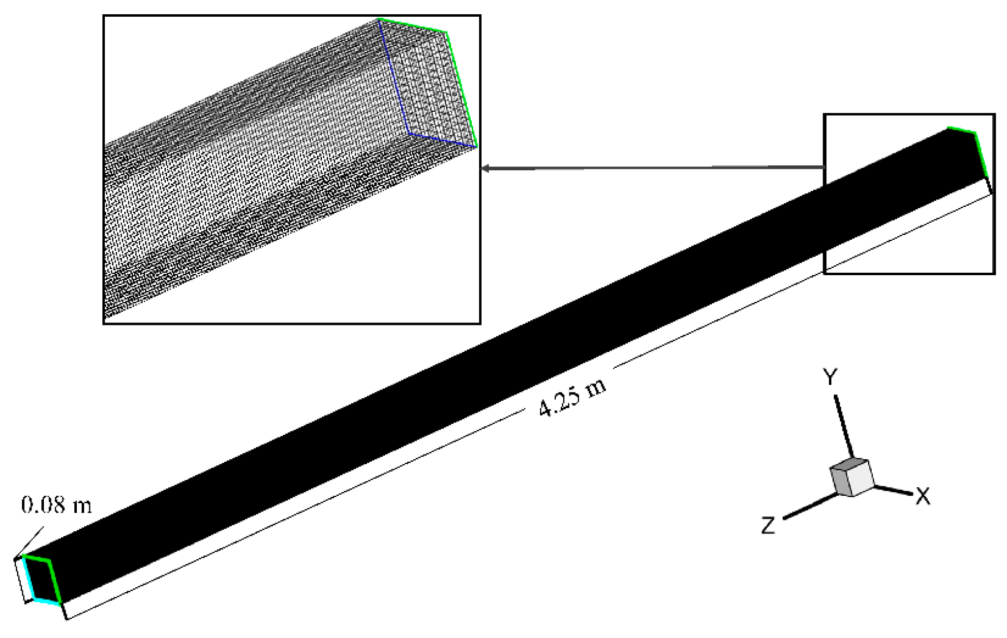
The solution for the governing equations includes both a temporal and spatial discretization processes. In this paper, when both FLSF and HDSF are equal to one, a 4.25-m long and 0.08-m by 0.08-m cross-section geometric model is employed, as shown in Figure 1. The geometric model is discretized using structural 64-mm3 hexahedron meshes, with the average aspect ratio equal to unity. A grid resolution analysis, ranging from 8 to 4096 mm3, has been done beforehand, considering the relationship of the relative deviation with respect to the 8-mm3 case for the base model. The result shows a relative deviation of 4% when the selected resolution is applied. Under such circumstances, the meshed domain comprises 245,939 nodes and 217,600 hexahedral cells. The relative mesh size will not change when the FLSF or HDSF scaling factors increase or decrease. However, the absolute mesh size changes with scaling factors; e.g., for a geometry when FLSF equals 2 and HDSF equals 4, the mesh size is 0.8 mm in the axial direction and a 1.6 mm by 1.6 mm cross-sectional dimension. The change of the absolute dimensions of cells will not cause considerable errors, which has been proven up to the scale of 1:100 (both longitudinal and horizontal) [4]. The combination of eight HDSFs (1, 2, 4, 8, 16, 32, 64 and 100) and five HDSFs (0.5, 1, 2, 4 and 8) were investigated in this paper on the basis of a 0.08-m by 0.08-m by 4.25-m gallery when both scaling factors equal to unit.
Figure 1. Mesh of geometric model.
Minerals 06 00002 g001
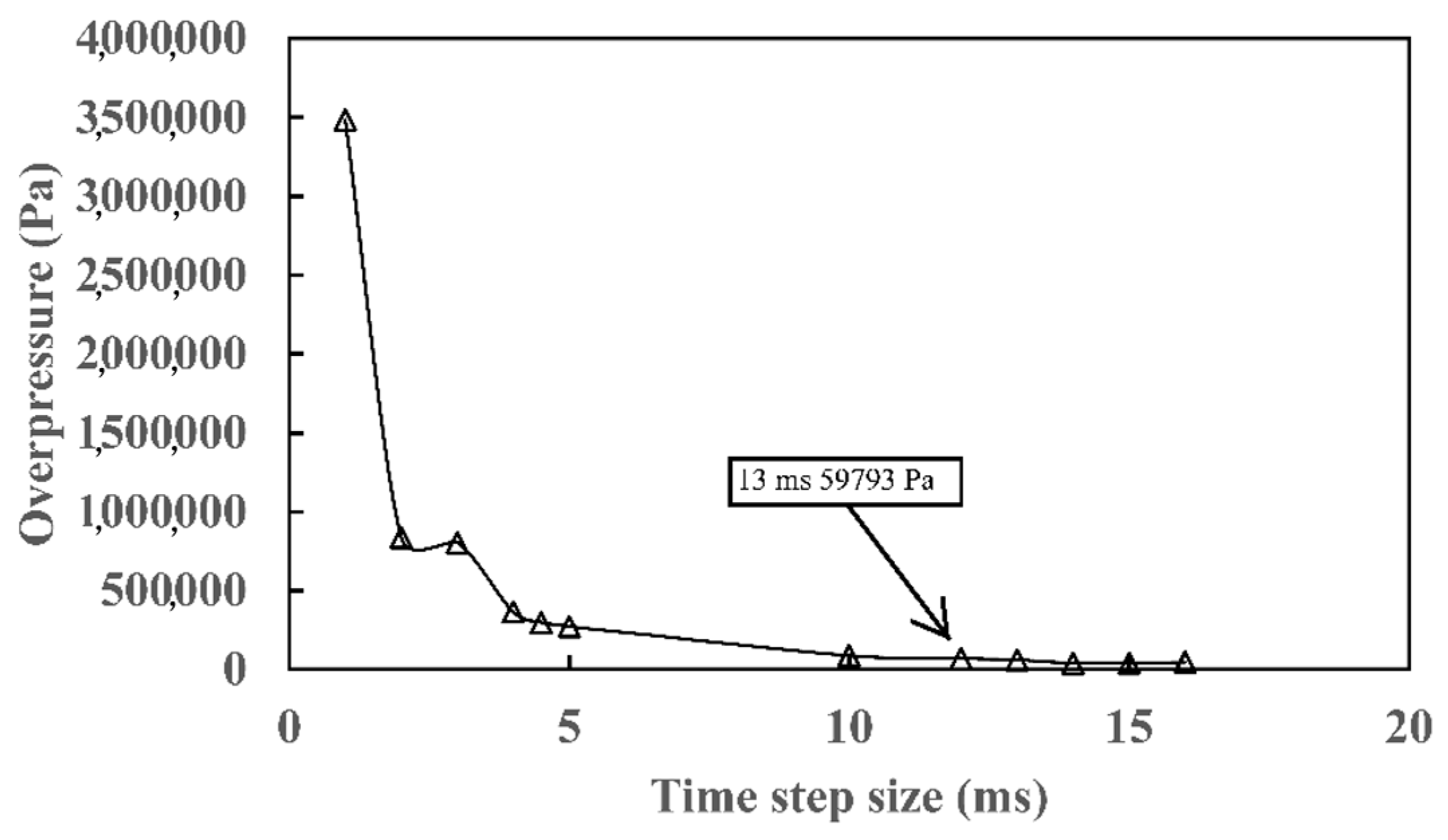
The temporal discretization of the time duration for an appropriate time step size has significant influence on the calculation stability. As gaseous combustion is highly transient, the time step size should also be set. The time step size analysis is, therefore, applied. The predicted overpressure of 9.5% methane/air mixture when unit-scaling factors are applied decreases monotonically with respect to time, as illustrated in Figure 2.
The time step size converges at around 13 ms (milliseconds) when the overpressure approaches convergence. Simulation results show that the peak overpressure of 59,793 Pa agrees with the experimental results (59,588 Pa) for the same setup. Given the mesh size discussed above, the Courant-Friedrichs-Lewy number ( C F L = Δ t u / Δ x ; u is characteristic flame speed) is close to 1.3, which is therefore acceptable since an implicit temporal discretization scheme is used in this research.
Figure 2. Time step convergence profile.
Minerals 06 00002 g002

3.2. Numerical Details

In this research, the CFD solver ANSYS Fluent, Cortex Version 14.5.0 is used. Smagorinsky-Lily and C-equation progress variable model, described in Section 2.1 and Section 2.2, were used as the turbulence and combustion models, respectively. Methane explosions are common in industrial operations and, especially, in underground mining operations; therefore, a 9.5% methane/air mixture was selected to be the objective explosive in this paper [19]. This percent mixture is considered close to stoichiometry; a Bounded Central-difference numerical scheme is used in convection terms and a second order upwind scheme is applied in diffusion terms. The Semi-Implicit Method for Pressure Linked Equations (SIMPLE) are incorporated, and a least squares cell based scheme for gradient treatment in deflagration cases; turbulence plays a key role in characterizing a combustion computational field. However, when detonation occurs in some high FLSF to HDSF scenarios, the presence of turbulence can be safely ignored [20]. Instead, blast-wave generation and propagation dominate. Therefore, scenarios with peak overpressures greater than the calculated CJ-detonation overpressure will be recalculated using the Euler solver with Favre-averaged parameters and an explicit temporal scheme. The effect of turbulence is eliminated in detonation cases.
CFD calculations were conducted using personal computers with quad-core i7 3770K and 16 Gb Raw. Eight parallel processes were used in ANSYS Fluent and 20 iterations were assigned per time step for deflagration calculations. The residuals of fluid parameters are generally on e−5 level.

4. Validation

The LES turbulence model in the geometry where the FLSF and HDSF were equal to one was validated by the experimental results. The experiment was conducted at the Institute of Methane Safety Control and Utilization, China University of Mining and Technology (CUMT), Xuzhou, China. The customized experimental system consists of six main parts: igniter, main explosion ducts, flexible duct with geometric changes, gas source, sensors, and data collection system, as illustrated in Figure 3.
The explosion duct is 11.35 m long, and has an 80 mm × 80 mm square cross-section with a maximum overpressure of up to 20 MPa. The data collection system (model: CS20182-32) (with 32 Channels, 20 MHz collection frequency and 1 bit accurcy) is connected to the pressure and light-sensitive sensors along the duct. These sensors are used to capture overpressure and flame signals during an explosion test.
Figure 3. Schematic of the methane explosion experiment system (not to scale).
Minerals 06 00002 g003
Overpressure/time relationship, impulse arrival time, and duration of impulse are three key factors to characterize a gaseous explosion [17,20]. Experimentally recorded overpressure history at a 9.5 length to diameter scaled distance from the ignition source was used to evaluate the numerical predictions. In addition to the LES model, the standard k-ε model was also incorporated in this section for comparison purpose. Standard wall function was used for the standard k-ε model. Figure 4 demonstrates the comparison of overpressure histories among the experimental results and numerical predictions when using the LES model and standard k-ε model, respectively.
Figure 4. Overpressure/time relationship at 9.5 length to diameter scaled distance from ignition source.
Minerals 06 00002 g004
As Figure 4 illustrates, LES provides a better prediction than the standard k-ε model because of the inherent drawback for a time-averaged turbulence model to resolve a highly transient flow [21] and the requirement of a resolving boundary layer is more stringent than the LES model. A finer mesh of the boundary layer for the k-ε model could lead to a better prediction. However, it is computationally expensive. Nevertheless, both models failed to resolve the negative phase and the instabilities after the main impulse. The LES model provides a prediction of peak overpressure at 63,553 Pa comparing to the 59,663 Pa from the experiment. The relative error is 7%. The LES model also gives a good prediction of the arrive-time of overpressure impulse. However, up to 30% relative error was found in predicting the duration of the positive phase of blast-waves for the LES model. Considering the overall performance of the LES model, it is a reasonable alternative for the k-ε model in modeling methane explosions. As the premixed C-equation combustion model can only be applied in a deflagration regime, scenarios with peak overpressure larger than the theoretical CJ detonation pressure should be repeated using the Euler solver. The validation of the Euler solver to simulate a methane detonation has been discussed in Oran’s work and will not be repeated here [22] as the influence of turbulence is beyond the scope of this method. There is also no need to evaluate the detonation scenarios under the given geometries.

5. Results and Discussion

Peak overpressure/time relationships at the scaled distance 9.5 for the combinations of eight HDSFs (1, 2, 4, 8, 16, 32, 64 and 100) and five FLSFs (0.5, 1, 2, 4 and 8) were tested and will be presented in this section.

5.1. FLSFs

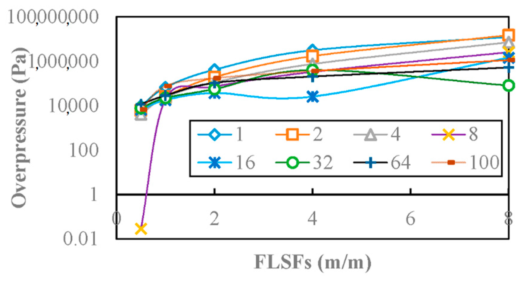
Peak overpressures for FLSFs equal 0.5, 1, 5, 4 and 8, when combined with eight HDSFs, are shown in Figure 5.
The peak overpressure for all FLSF-HDSF combinations increases monotonically with the FLSF, except in the case where HDSF equals to 32, as illustrated in Figure 5. This case shows a slight decrement at an FLSF of 8. This means that the increase of gas-fill length would generally facilitate the overpressure generated by a methane/air explosion, regardless of gas-fill space cross-sections. In addition, the cases that have larger HDSFs reproduced lower peak overpressures than those with smaller HDSFs. In the case where HDSFs equal to 32 and 64, significantly low overpressures were detected. This occurs because the laminar flame velocity is low (0.42 m/s) and the flame takes longer to reach the walls, which leads to a delay in laminar to turbulence transition. On the other hand, the space is less confined in large diameter cases and the overpressure is, therefore, attenuated. Note that, in the six cases with smaller FLSFs, which have higher overpressure than theoretical minimum CJ-detonation pressure, detonation is triggered instead of deflagration. This result is in good agreement with the experimental results, where high length-to-diameter ratio is required by DDT [23].
Figure 5. Peak overpressure for five gas-fill length scaling factors (FLSF) combined with hydroulic diameter scaling factors (HDSF).
Minerals 06 00002 g005

5.2. HDSFs

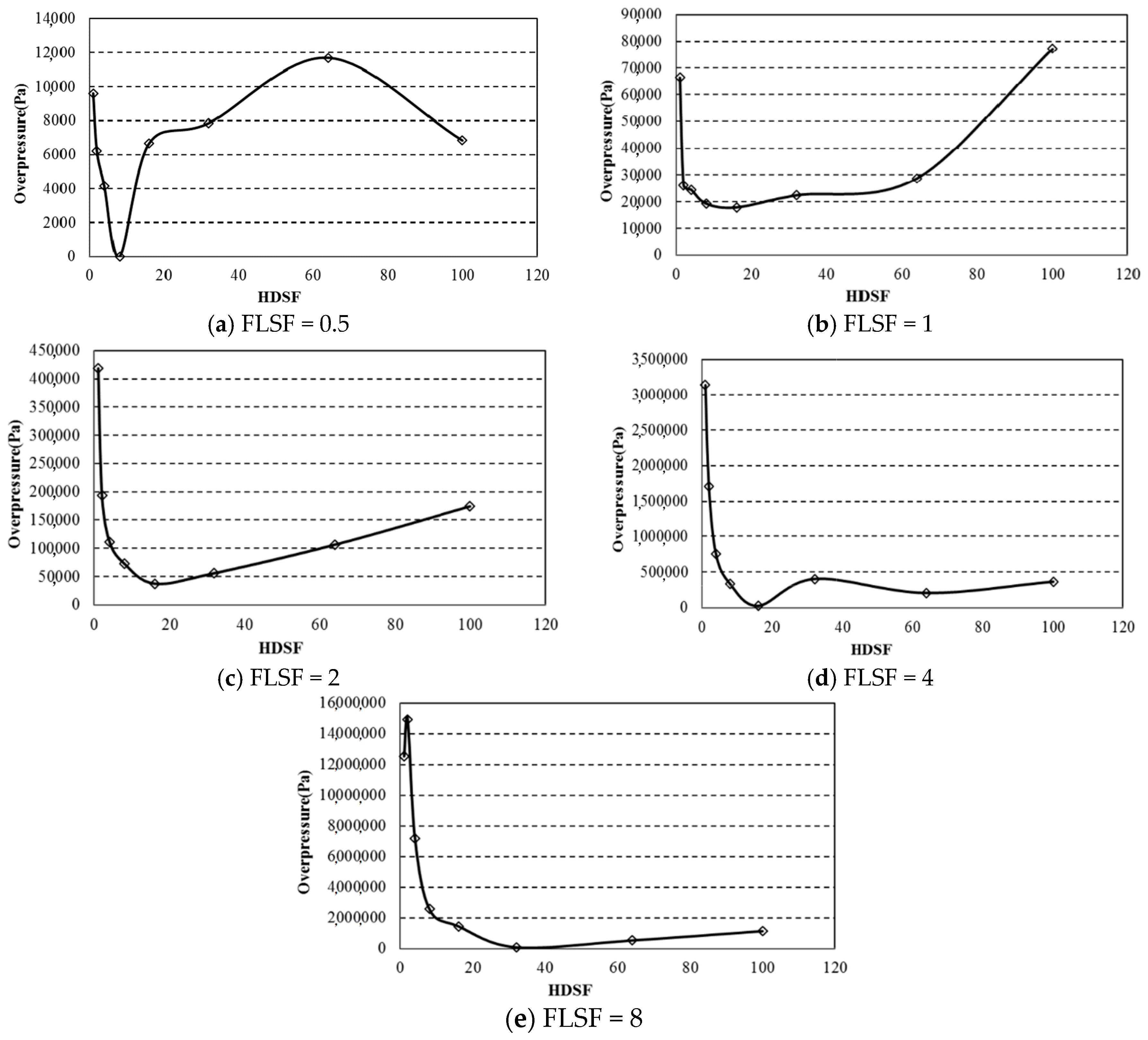
The variation of peak overpressure and HDSF relationships, when combined with five selected FLSFs, however, do not follow a monotonic trend, as observed in FLSF cases. The Peak overpressure for each FLSF will be demonstrated separately in Figure 6.
Figure 6 illustrates the overpressure profile; with U shapes as HDSFs increase. In the FLSF = 0.5 group, the peak overpressure decreases sharply as HDSF increases, until it reaches 0 when HDSF is equal to 8. It rebounds after 8 and continues increasing until the peak value is obtained at a HDSF of 64. Afterwards, a slight decrement is observed. When FLSFs are equal to 1, 2 and 4, the peak overpressure yields a similar trend, with two local peak values when HDSF equals to 0.5 and 100. Four detonation scenarios are detected in the latter two groups, close to the left side of the curves. The FLSF 8 group has a slight increment when the HDSF changes from 0.5 to 1. Then, the peak overpressure decreases to the minimum when the HDSF is equal to 32. This indicates that a large cross-section of gas-fill space does not necessarily reproduce large overpressure, and can be opposite in most cases. The overpressure tend to be significant in FLSF of 2, 4 and 8 groups, which depicts that a certain level of gas-fill length is required to produce a violent gaseous explosion. A room-like fuel-filled space is less likely a stimulus for detonation to occur.
Figure 6. Peak overpressure and HDSF relationships when FLSF equals to (a) 0.5; (b) 1; (c) 2; (d) 4 and (e) 8.
Minerals 06 00002 g006
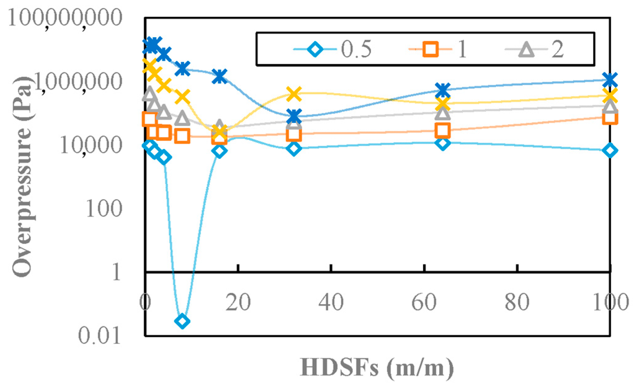
Figure 7 summarizes the interrelationships between the predicted overpressure of all five FLSF groups and the theoretical calculated CJ-detonation value. Six data points, which were transformed to detonation regimes, are all in a small HDSF region (the maximum HDSF equals 8). However, larger FLSFs facilitates the rise of overpressure, which has already been seen in FLSF analysis.
Figure 7. Peak overpressure of HDSFs and CJ-detonation pressure.
Minerals 06 00002 g007

5.3. Combined Effect

The effects of the longitudinal and horizontal scales on the peak overpressure have been discussed in Section 5.1 and Section 5.2. The combined effect of HDSF and FLSF will be discussed in this section.
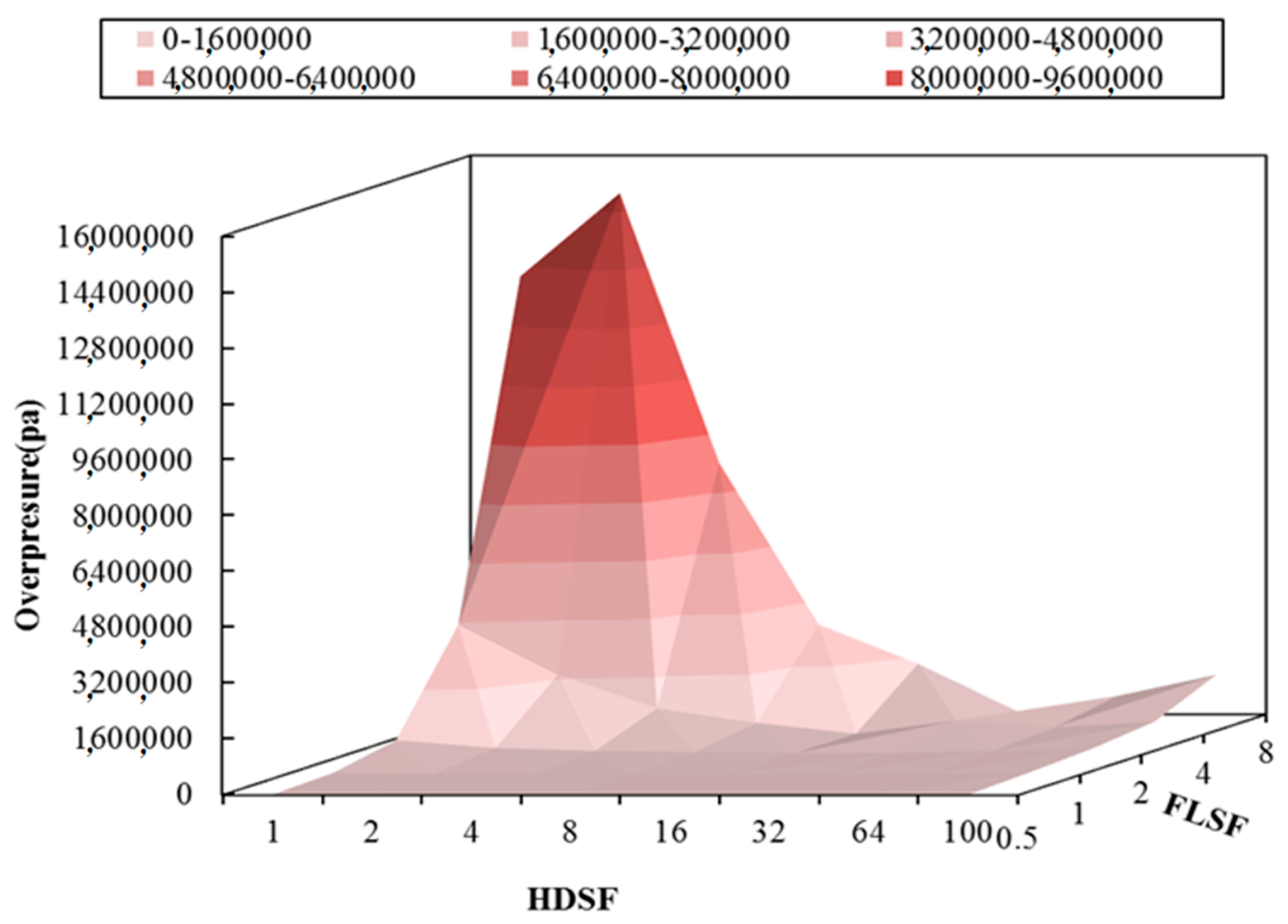
Figure 8 provides a clear view of the triadic relationship among FLSFs, HDSFs, and peak overpressures, incorporated in a three dimensional ordinate system.
In Figure 8, the regions with darker colors have higher peak overpressures than lighter ones. The region in light red on the lowest level of the surface represents deflagration regime (smaller than CJ-detonation value), otherwise it is in a detonation regime. As can be seen, the detonation regime is located where a large gas-fill length to hydraulic diameter ratio is obtained. The minimum ratio is 54 in this case, where 9.5% methane/air mixture is used. The overpressure also increases slightly for larger FLSFs when the HDSF is larger than 64. This is due to the increase in the volume of methane accumulation, which leads to an increment of the total energy of explosives. However, comparing the overpressure increment resulted from geometric issues, the magnitude of the increment is much less significant. In addition, the results of detonation peak overpressure should be used with special caution, due to the limitations of the premixed combustion model employed in this study.
Figure 8. Effects of FLSF and HDSF on peak overpressure (Pa).
Minerals 06 00002 g008

6. Conclusions

This research provides an approach to investigate the scale effects for both longitudinal and horizontal directions on peak overpressure, generated by a stoichiometric methane explosion. Both deflagration and detonation regimes are incorporated. Three major conclusions are drawn from the discussion provided in Section 5.1 to Section 5.3: (1) both FLSF and HDSF have significant impact on the overpressure generated by a methane explosion; (2) detonations are likely to occur when the ratio of gas-fill length to hydraulic diameter of an explosion duct is larger than 54, which generates a much higher overpressure than in deflagration cases; (3) explosion overpressures increase with hydraulic diameter of a geometry within a deflagration regime. To sum up, the overpressure of a methane explosion would increase in two circumstances; length to diameter ratio increases as the geometry changes, and gas accumulative volume increases as its scale is enlarged.
The focus of future work will be on the investigation of the scale effects on fuel-lean and fuel-rich gaseous explosions. In addition, more data-points can be obtained by increasing the density when selecting variables. More flammable gases could be tested, which could yield different results. This work would contribute to solving a wide range of problems with respect to explosion mitigation and explosives management for energy and processing industries.

Acknowledgments

This work is financially supported by grants from the National Natural Science Foundation of China (Grant No. 51504045). Gas Explosion Lab of China University of Mining and Technology (CUMT) provided the platform for experimental study.

Author Contributions

Liang Wang did experiment and built numerical simulation; Sisi Que analyzed experimental data; Jerry Tien designed experiment; Nassib S. Aouad is the co-developer of the numerical model.

Conflicts of Interest

The authors declare no conflict of interest.

References

  1. McPherson, M.J. Subsurface Ventilation Engineering; Mine Ventilation Services: California, CA, USA, 1993; pp. 21.45–21.46. [Google Scholar]
  2. Catlin, C.A.; Johnson, D.M. Experimental scaling of the flame acceleration phase of an explosion by changing fuel gas reactivity. Combust. Flame 1992, 88, 15–27. [Google Scholar] [CrossRef]
  3. Catlin, C.A. Scale effect on the external combustion caused by venting of a confined explosion. Combust. Flame 1991, 83, 399–411. [Google Scholar] [CrossRef]
  4. Zhang, Q.; Pang, L.; Zhang, S.X. Effect of scale on flame speeds of methane-air. J. Loss Prev. Process Ind. 2011, 24, 705–712. [Google Scholar] [CrossRef]
  5. Van Wingerden, C.J.M. On the scaling of vapour cloud explosion experiments. Chem. Eng. Res. Des. 1989, 67, 339–347. [Google Scholar]
  6. Di Sarli, V.; di Benedetto, A.; Russo, G.; Jarvis, S.; Long, E.J.; Hargrave, G.K. Large eddy simulation and PIV measurements of unsteady premixed flames accelerated by obstacles. Flow Turbul. Combust. 2009, 83, 227–250. [Google Scholar] [CrossRef]
  7. Di Sarli, V.; di Benedetto, A.; Russo, G. Using large eddy simulation for understanding vented gas explosions in the presence of obstacles. J. Hazard. Mater. 2009, 169, 435–442. [Google Scholar] [CrossRef] [PubMed]
  8. Di Sarli, V.; di Benedetto, A.; Russo, G. Sub-grid scale combustion models for large eddy simulation of unsteady premixed flame propagation around obstacles. J. Hazard. Mater. 2009, 180, 71–78. [Google Scholar] [CrossRef] [PubMed]
  9. Di Sarli, V.; di Benedetto, A. Sensitivity to the presence of the combustion submodel for large eddy simulation of transient premixed flame—Vortex interactions. Ind. Eng. Chem. Res. 2012, 51, 7704–7712. [Google Scholar] [CrossRef]
  10. Di Sarli, V.; di Benedetto, A. Effects of non-equidiffusion on unsteady propagation of hydrogen-enriched methane/air premixed flames. Int. J. Hydrog. Energy 2013, 38, 7510–7518. [Google Scholar] [CrossRef]
  11. Zhang, Q.; Pang, L.; Liang, H.M. Effect of scale on the explosion of methane in air and its shockwave. J. Loss Prev. Process Ind. 2011, 24, 43–48. [Google Scholar] [CrossRef]
  12. Hinze, J.O. Turbulence; McGraw-Hill Publishing Co.: New York, NY, USA, 1975. [Google Scholar]
  13. ANSYS, Inc. Anon ANSYS FLUENT Theory Guide; ANSYS, Inc.: Canonsburg, PA, USA, 2011. [Google Scholar]
  14. Zimont, V.; Polifke, W.; Bettelini, M.; Weisenstein, W. An efficient computational model for premixed turbulent combustion at high reynolds numbers based on a turbulent flame speed closure. J. Gas Turbines Power 1998, 120, 526–532. [Google Scholar] [CrossRef]
  15. Ewald, J. A Level Set Based Flamelet Model for the Prediction of Combustion in Homogeneous Charge and Direct Injection Spark Ignition Engines. Available online: tocs.ulb.tu-darmstadt.de/177689706.pdf (accessed on 13 December 2015).
  16. Londoño, L.F.; López, C.E.; Cadavid, F. Hugo burbano determination of laminar flame speed of methane/air flames at subatmospheric conditions using the cone method and CH emission. Dyna 2013, 80, 130–135. [Google Scholar]
  17. Zhou, X.Q.; Wu, B.; Xu, J.D. Basic characters of gas explosion in underground coal mines. China Coal Mines 2002, 28, 8–11. [Google Scholar]
  18. Needham, C.E. Shock Wave and High Pressure Phenomena. In Blast Wave; Springer Express: Somerset, UK, 2010; pp. 87–99, 293–302. [Google Scholar]
  19. Pekalski, A.A.; Schildberg, H.P.; Smallegange, P.S.D.; Lemkowitz, S.M.; Zevenbergen, J.F.; Braithwaite, M. Determination of the explosion behavior of methane and propane in air or oxygen at standard and elevated conditions. Process Saf. Environ. Prot. 2005, 83, 421–429. [Google Scholar] [CrossRef]
  20. Yáñez, J.; Kotchourko, A.; Lelyakin, A.; Gavrikov, A.; Efimenko, A.; Zbikowski, M.; Makarove, D.; Molkove, V. A comparison exercise on the CFD detonation simulation in large scale confined volumes. Int. J. Hydrog. Energy 2011, 36, 2613–2619. [Google Scholar] [CrossRef]
  21. Di Sarli, V.; di Benedetto, A.; Russo, G. Large eddy simulation of transient premixed flame—Vortex interactions in gas explosions. Chem. Eng. Sci. 2012, 71, 539–551. [Google Scholar] [CrossRef]
  22. Oran, E.S.; Gamezo, V.N. Origins of the deflagration-to-detonation transition in gas-phase combustion. Combust. Flame 2007, 148, 4–47. [Google Scholar] [CrossRef]
  23. Zipf, R.K.; Sapko, M.J.; Marchewka, W.P.; Mohamed, K.M.; Weiss, E.S.; Addis, J.D.; Karnack, F.A.; Sellers, D.D.; Gamezo, V.N.; Oran, E.S.; et al. Methane-air detonation experiments at NIOSH Lake Lynn laboratory. J. Loss Prev. Process Ind. 2013, 26, 295–301. [Google Scholar] [CrossRef]