Article

Comprehensive Technical Support for High-Quality Anthracite Production: A Case Study in the Xinqiao Coal Mine, Yongxia Mining Area, China

1
IoT Perception Mine Research Center, China University of Mining & Technology, Xuzhou 221008, China
2
The National and Local Joint Engineering Laboratory of Internet Application Technology on Mine, China University of Mining & Technology, Xuzhou 221008, China
3
School of Mines, China University of Mining & Technology, Xuzhou 221116, China
*
Author to whom correspondence should be addressed.
Minerals 2015, 5(4), 919-935; https://doi.org/10.3390/min5040533
Submission received: 14 September 2015 / Revised: 24 November 2015 / Accepted: 8 December 2015 / Published: 14 December 2015

Abstract

:
The effective production of high-quality anthracite has attracted increasing global attention. Based on the coal occurrence in Yongxia Mining Area and mining conditions of a coalface in Xinqiao Coal Mine, we proposed a systematic study on the technical support for the production of high-quality anthracite. Six key steps were explored, including coal falling at the coalface, transport, underground bunker storage, main shaft hoisting, coal preparation on the ground, and railway wagon loading. The study resulted in optimized running parameters for the shearers, and the rotating patterns of the shearer drums was altered (one-way cutting was employed). Mining height and roof supporting intensity were reduced. Besides, loose presplitting millisecond blasting and mechanized mining were applied to upgrade the coal quantity and the lump coal production rate. Additionally, the coalface end transloading, coalface crush, transport systems, underground storage, and main shaft skip unloading processes were improved, and fragmentation-prevention techniques were used in the washing and railway wagon loading processes. As a result, the lump coal production rate was maintained at a high level and fragmentation was significantly reduced. Because of using the parameters and techniques determined in this research, high-quality coal production and increased profits were achieved. The research results could provide theoretical guidance and methodology for other anthracite production bases.

1. Introduction

As one of six approved domestic anthracite production bases, Yongxia Mining Area (YMA) of Henan Province in China has an intended capacity of 10 million tons yearly. The quantity of anthracite is about 20% of all coal produced, but contributes 45% of total coal income. Despite the poor performance of the coal market over the past three years, anthracite sales have not been plagued with overstocking and sluggish demand. Therefore, it is significant to provide a series of customized technical supports for producing high-quality anthracite.
The Lump coal production rate (LCPR) is a key index of anthracite’s quality. Among the various factors affecting the LCPR, physical properties and occurrence conditions of the coal seam are the most important ones [1,2,3]. The LCPR of anthracite has been intensively studied over the past few decades and various reports have been published, all of which can be categorized into the following five aspects:
(1) Reformations of shearer drums [4,5,6,7,8]. Since 1972, attempts have been made to increase the LCPR by enlarging the chipping areas of cutting picks, optimizing their arrangements and improving drum parts in Poland, Russia and China.
(2) Improvements in blasting methods [9,10,11,12,13]. The Cardox blasting technique (CBT) has been widely applied to increase LCPR in Turkey and Colombia. Also, based on the controlled blasting principle, loose control blasting, uncoupled water medium millisecond blasting, and high-pressure gas millisecond blasting have been developed to improve the blasting effect.
(3) Adjustments in mining techniques. Zhao et al. [14] proposed a method that combines the blasting mining workface and fully mechanized workface to achieve enhanced LCPR. Song et al. [15] proposed a technique involving low cutting depth and fast traction two-way cutting using an AM-500 Shearer (TMM Group, Taiyuan, China), and achieved to enhance LCPR from raw coal. Zhang et al. [16] introduced a coal planer (DBT Company, Lünen, Germany) used in the mining of thin coal seam with a thickness of 1 m. The LCPR was increased using effective mining of workface obviously.
(4) Optimizations of transport and storage. Li et al. [17] reported a stretchable mini-sized bin to mitigate the high drop damage on coal in the bunker. As a result, lump coal losses were reduced by 6%. Kozan et al. [18] proposed a demand-responsive decision support system by integrating the operations of coal shipment, coal stockpiles and coal railing within a whole system. A generic and flexible scheduling optimization method is developed to identify, represent, model, solve and analyze the coal transport problem in a standard and convenient way. Zhang et al. [19] reported the air-supported membrane shed as a new building structure for storing coal. Wang et al. [20] reported wave-like coal drops with horizontally attached transloading points and spiral coal drops with vertically attached transloading points based on the in situ analysis of underground conditions. As a result, the fragmentation of mined anthracite was reduced. Lv et al. [21] introduced a massive vertical bunker on-wall buffer system with a unique structure and fixing patterns. Compared with conventional column coal drops placed in the bunker center, this buffer system effectively prevented coal from fragmenting during its dropping process, thus lessening lump coal loss. Liu et al. [22] reported an innovative methodology for optimizing the coal train scheduling problem. To construct feasible train schedules, an innovative constructive algorithm called the SLEK algorithm is proposed. To optimise the train schedule, a three-stage hybrid algorithm called the SLEK-BIH-TS algorithm is developed based on the definition of a sophisticated neighbourhood structure under the mechanism of the Best-Insertion-Heuristic algorithm and Tabu Search metaheuristic algorithm. Singh et al. [23] described a MILP (Mixed Integer Linear Programming) model for determining the capacity requirements, and the most cost effective capacity improvement initiatives, to meet demand while minimizing the total cost of infrastructure and demurrage. Then, they presented results of computational experiments on the model’s performance along with a comparison of the model’s output with detailed analyses from the coal chain analysts and planners.
(5) Innovations in coal preparation plants. Wang et al. [24] reported that an ultrasonic wave sensor was placed on top of the lump coal buffer bunker, and the work site was equipped with coal level alarms. The dropping height was maintained between 2–3.8 m, and in this way, both the LCPR and safety were enhanced. Xie et al. [25] introduced a sizing crusher (FP5012, ZGME Company, Zhengzhou, China) was used to increase the size uniformity of crushed particles and decrease the over-crushing rate. Chen et al. [26] introduced attempts made to adjust the unloading opening size, optimize the separating density, and perform separate storage of filtrated coal. As a result, the LCPR of anthracite has been increased by 4.5%.
In summary, despite great achievements made in producing high-quality anthracite, previous reports focus on only one key step, and few attempts have been made to investigate the entire production process in an integrated way. As we know, underground mining in itself is a complicated process, which is easily affected by several determining factors (e.g., geological conditions, mining techniques, and production systems). Therefore, a significant improvement in the quality of mined anthracite is a systematic undertaking that can only be achieved by modifications in all relevant production links. In other words, overall product quality is determined by the poorest performance of individual processes (Cannikin Law). Based on the occurrence of the coal seam in YMA and the mining conditions of a coalface in Xinqiao Coal Mine (XCM), we proposed a systematic study on the technical supports for the production of high-quality anthracite in this paper (the remaining sections includes mine conditions and mining techniques, techniques for increased LCPR of raw coal, fragmentation-prevention techniques for lump coal, and economic benefits). It should be pointed out that the proposed coal mining methods are only used for underground mining. The results of this study have been widely adopted for high-quality anthracite production in other coal mines, YMA.

2. Mine Conditions and Mining Techniques

As shown in Figure 1, XCM is located in the southwest part of Yongcheng City, Henan Province, China. Its terrestrial coordinates are 116°13′34″–116°18′07″ East longitudes, 33°47′21″–33°53′58″ North latitudes. With a length of 14 km (North to South) and a width of 1.6–4 km (East to West), the mine has a total area of 36 km2. As one of the largest coal mines managed by Yongcheng Coal & Power Company Limited (YCPLC), XCM has been designed with a capacity of 1.2 million tons each year and a service life of 56.6 years. A pair of shafts was established in a uni-vertical up and down pattern and with a horizontal elevation of −550 m. Mining is executed in a bottom up fashion; the bottom coal seam (#22) is mined before mining the top coal seam. In addition, horizontal mining occurs in a forward pattern.
Figure 1. The geographical location of XCM.
Minerals 05 00533 g001
The #22 coal seam of the North Second Panel (NSP) was mined first. The generalized column of the NSP is presented in Figure 2. The geological structure and occurrence conditions of this field are favorable for mining; the coal seam thickness ranges from 1.69 to 4.34 m and the average thickness is 3.33 m. The dip angle ranges from 10° to 16° and the average angle is 13°. The roof of the #22 coal seam is made up of fine sandstone and sandy mudstone, with magmatic rock in some local regions. The base of the #22 coal seam is made up of mudstone and siltstone. In this area, strike longwall fully mechanized mining (FMM) (mining height is equal to 2.85 m) and roof caving (for mined-out areas) were employed.
Figure 2. The generalized column of the NSP.
Minerals 05 00533 g002

3. Techniques for Increased LCPR of Raw Coal

In coal mining, the LCPR is positively related to the unit price of the product and decrease of pulverized coal rate. Mostly, raw coal mining is the key stage of lump coal formation. Moreover, the parameters (running parameters and drum parameters) of the shearer and the mining methods play a key role in the formation of lump coal.

3.1. Optimization of Shearer’s Parameters

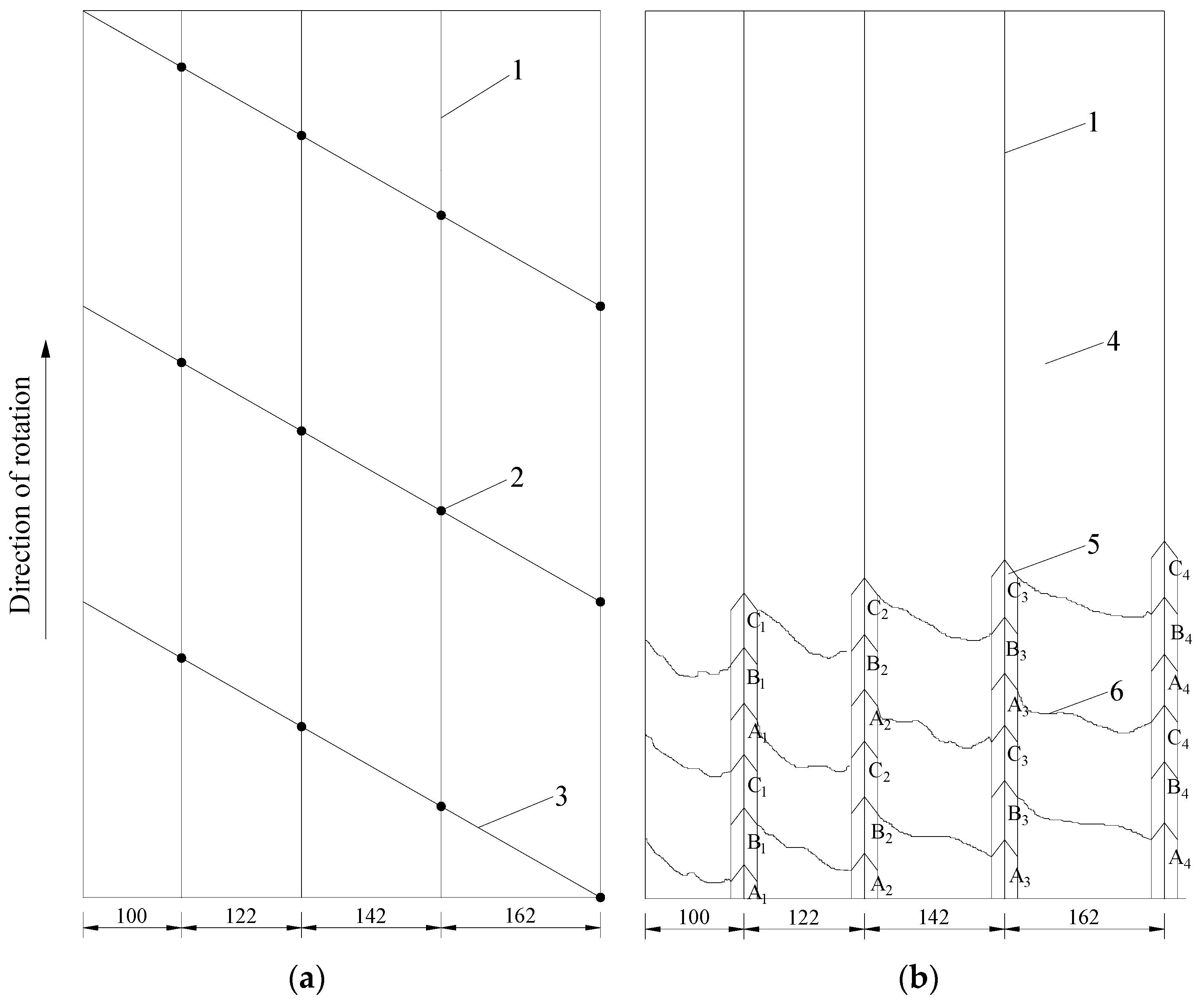
3.1.1. Mathematical Description of Shearer’s Cutting Thickness

The cutting thickness of a shearer refers to the thickness cut by each pick in one rotation of the drum. This parameter is not an intrinsic one; instead, it is a condition parameter that is determined by the arrangement of cutting picks, the rotating speed of the drum, and traction speed of the shearer [27,28]. Due to the effects of the drum rotation and shearer traction used for this study, arc-shape cutting was generated and the cutting shape was a crescent [29] (Figure 3).
Figure 3. The ranges of drum cutting thickness.
Minerals 05 00533 g003
The cutting thickness along the traction direction in one rotation can be expressed as [30]:
h max = 1000 v q z 1 n c
h ¯ = 2 π h max
where: vq is the traction speed of the shearer, m/min; z1 is the number of picks in a transversal (determined by the picks arrangement and the number of helical blades); nc is the rotating speed of the drum, r/min; hmax and h ¯ are the maximum and minimum cutting thickness, respectively.
According to Equations (1) and (2), cutting thickness is also determined by the picks arrangement and the number of helical blades.

3.1.2. Optimization of Running Parameters

According to the relationship between traction/rotating speeds and cutting thickness, the ratio of traction speed and rotating speed must be optimized to improve the LCPR. For instance, the traction speed/rotating speed ratio is decreased for hard coal while increased for soft coal. Previous studies have revealed that traction speed/rotating speed ratio should be kept within 0.0762–0.1524 [31,32]. The parameters of the double-drum shearers (MG200/500-QWD, TST Company, Beijing, China) currently used in XCM are as follows: traction speed is 0–6 m/min, drum diameter is 1600 mm, cutting depth is 630 mm, and designed drum rotating speed is 42 r/min. With consideration to the situation in this study, traction and rotating speeds were adjusted to 4–5 m/min and 35 r/min, respectively, so that the ratio remained at 0.11–0.14. As a result, the LCPR was enhanced by 3.8%.

3.1.3. Optimization of Cutting Pick Parameters

In theory, the LCPR can be enhanced by either increasing the pick length or decreasing the pick density. Nevertheless, both measures lead to increasing shearer vibrations, thus lessening the service life of the shearer. To counter this, a novel shearer drum with unique picks (Figure 4) was used in XCM. As shown in Figure 4a, the cutting blades presented large cutting depth and digging capabilities. Each drum had three blades and each transversal had three cutting picks; the distances between transversals could be 100, 122, 142, or 162 mm. The cutting cross-section of kerfs is shown in Figure 4b. Herein, A1–A4, B1–B4, and C1–C4 sketch the cross-sections of picks No. 1 to No. 4 on the blades.
Figure 4. A novel shearer drum with large cutting depth and digging capabilities: (a) arrangement of cutting picks on blades; (b) cutting cross-section of kerfs; 1, transversals; 2, cutting picks; 3, blades; 4, anthracite; 5, kerfs; 6, cracks.
Minerals 05 00533 g004
The 18 cutting picks on the plate were maintained, while the picks on the blade were reduced from six to four. Three cutting picks were installed on each transversal and the inter-transversal distance was increased from 80 to 162 mm. To mitigate the increased cutting resistance, a more powerful drum (Kennametal Company, Fort Mill, SC, USA) was employed. Meanwhile, high-strength point-attack picks (U92 and U94) were used in different situations: extended U92 picks (from 92 to 125 mm) were used for completed cutting cases, and U94 picks were used for coal seams with small structures. Since then, compared to the production using conventional drums, the LCPR was enhanced by 5.1%.

3.2. Allocation of Reasonable Mining Techniques

3.2.1. Selection of Rotating Direction of the Drums and Cutting Approach

To improve the stability of the shearer, the two drums rotated in opposite directions (front/rear equals clockwise/anti-clockwise or anti-clockwise/clockwise, as shown in Figure 5). Therefore, the cutting resistances on the different drums worked in opposite directions. Usually, a clockwise/anti-clockwise pattern was employed. This can be attributed to the fact that the specific power consumption was minimized when the front and rear drums were responsible for cutting and loading, respectively. Additionally, the floating dust was also reduced. Nevertheless, the anti-clockwise/clockwise pattern was used in XCM. In this case, the fragmentation of lump coal was reduced by 4.9%, as loading of both drums did not involve the rocker arm.
Figure 5. Clockwise/anti-clockwise or anti-clockwise/clockwise patterns of front and rear drums: 1, front drum; 2, rear drum; 3, rocker arm.
Minerals 05 00533 g005
Currently, two-way and one-way cutting approaches are both widely used in the mining industry. Theoretically, two-way cutting approaches are more effective than one-way cutting. However, two-way approaches are limited by various issues in practice. For instance, the height of the shearer body is limited by the thickness of the coal seam, and low underneath clearance may be met. The maximum underneath clearance of the shearer was 468 mm in this study, and coal cut by the front drum would accumulate at the front end of the shearer in front-rear cutting, which could result in undesired fragmentation. On the other hand, one-way cutting approaches showed reasonable efficiency, and the LCPR could be enhanced by using this method. Therefore, in this study, a rear-front one-way cutting approach was used and the coal was kept away from the bracket. Using one-way cutting approach, the NSP has an average yield of 100,000 tons each month, with the highest monthly yield of 180,000 tons.

3.2.2. Reduction of Mining Height and Roof Supporting Intensity

In cases of strong coal walls and roof, mining height and roof supporting intensity would be reduced accordingly to allow spontaneous caving of the top coal upon cutting (Figure 6). In this way, massive coal cubes can be gained at a relatively low drum rotating speed. At the same time, cutting resistance on the unit area is lessened. Mining height of the NSP was designed to 2.85 m and a dual-column shield hydraulic support (ZY4000/17.5/38, ZMJ Company, Zhengzhou, China, supporting height is 1.75–3.8 m and initial support is 3077 kN) was used. For practical purposes, the mining height was reduced from 2.85 to 2.80 m, and the initial support was lowered from 3077 to 2800 kN. As a result, the LCPR was enhanced by 3.7%.
Figure 6. Schematic illustration of the coalface mining process.
Minerals 05 00533 g006

3.2.3. Implementation of LPMB on Coal Mass

In mining, many specific situations arise. For instance, some mines are located in geological crack zones, while others have issues of parting bands. Without additional measures, the LCPR of the product could be extremely low. Previous studies reported positive effects on the LCPR using blasting. In accordance with that, LPMB was executed on the coal body based on the variation of the coal seam thickness. More specifically, a loose blast was conducted once a day so that the presplitting depth met the need during working progress. Blasting was carried out while mine maintenance was conducted. In situ measurements revealed that the LCPR was increased by 12.37% (Table 1) with LPMB and FMM.
Table 1. LCPR comparison of two different mining techniques.
Mining TechniqueTotal Output (t)Lump Quantity (t)LCPR (%)Cutting Way
LPMB + FMM1st: 390186.547.82Average: 46.47One-way
2nd: 390174.344.69
3rd: 390182.946.90
FMM1st: 390134.534.49Average: 34.10One-way
2nd: 390131.933.82
3rd: 390132.634.00

4. Fragmentation-Prevention Techniques for Lump Coal

As it will undergo long transport routes (including coalface end transloading, transport through headgate, panel, and main roadway), lump coal mined from the coalface by the shearer is stored in an underground bunker and hoisted to the surface. Raw coal will be also washed and sieved in a series of processes that involve repetitive squeezing, colliding and abrading (as well as secondary crushing of massive cubes), which results in reduction of LCPR. Indeed, a large amount of coal is pulverized into powder, causing a severe decline in the quality of anthracite. In this section, we proposed a study of fragmentation-prevention techniques for lump coal in view of the whole coal flow system.

4.1. Principles of Coal Fragmentation

Fragmentation refers to the process in which large lumps are crushed into smaller ones. The collision of coal cubes against one another is believed to be the main cause of fragmentation [33,34]. It is generally believed that the LCPR of the final product is positively related to the percentage of large lumps in the raw coal. However, the LCPR of the final product is also affected by various reasons from the transport and transloading systems. Particularly, collision is regarded as a main reason for the LCPR of the final product. Despite the limited understanding of lump coal fragmentation principles, the collisions can be generally described by the following equation (Momentum Theorem) [35]:
F = m ( v t v o ) t
where: F is the force experienced by the cube during collisions; m is the mass of the cube; t is the collision time; v o and v t are the velocities before ( v o = 2 g h ) and after collisions, respectively.
According to Equation (3), the collision force experienced by the lumps is determined by the collision time t, lump mass m, and velocities before and after collisions ( v o and v t ). In most cases, v t is negligible, as lumps after collision are static. According to classical physics, v o is positively related to the falling height ( v o = 2 g h ). As the inner surface (made of concrete) of bunker is rigid, the collision time is extremely short. As a result, the collision force is large and the lumps are easily fragmented. Additionally, the force on each lump increases with its mass. Therefore, the LCPR is reduced as the average lump mass increases.

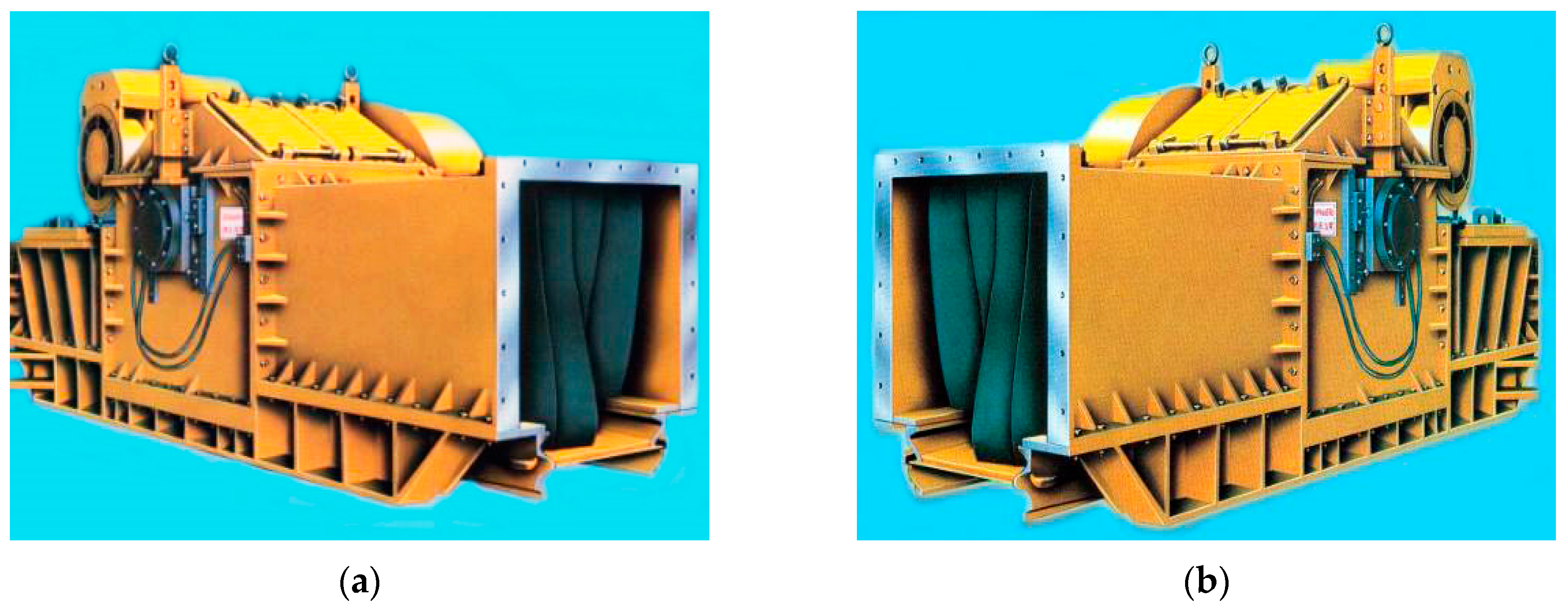
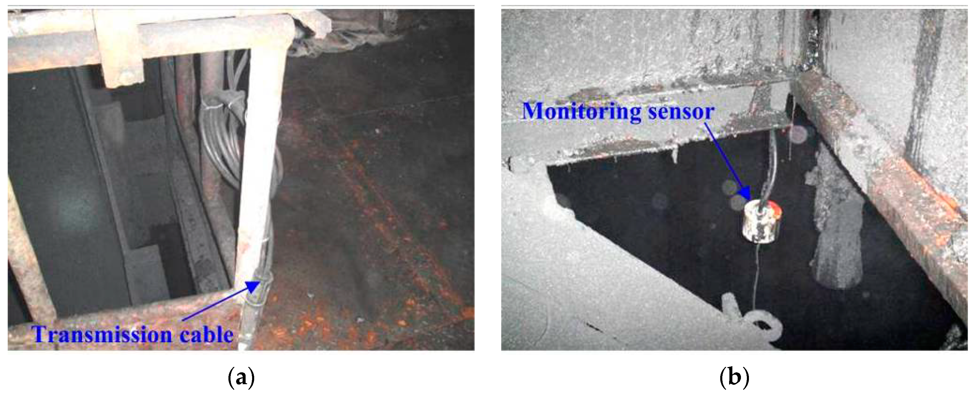
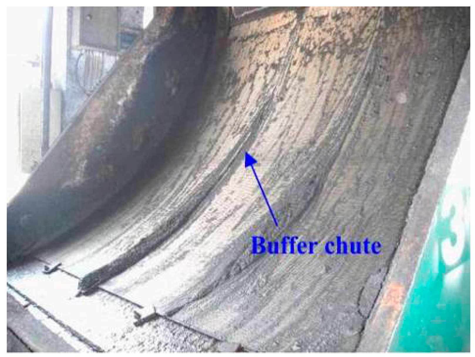
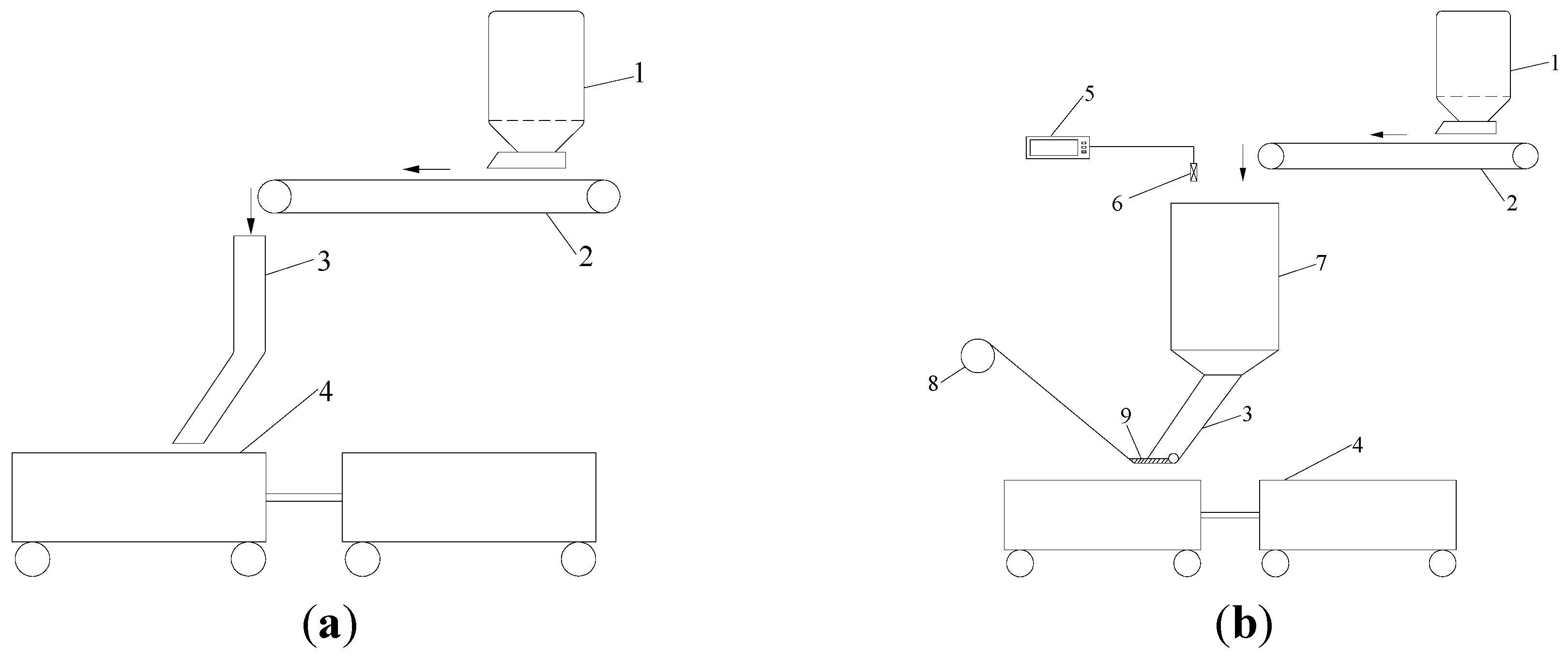
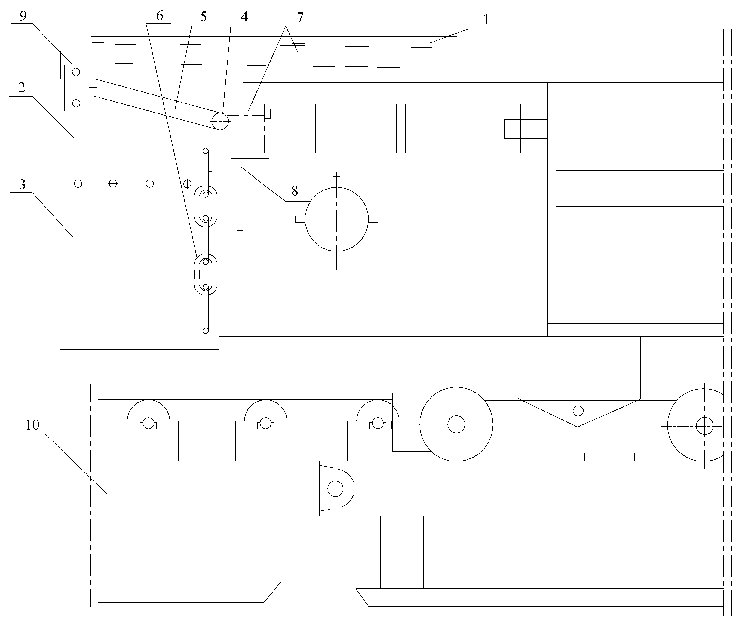
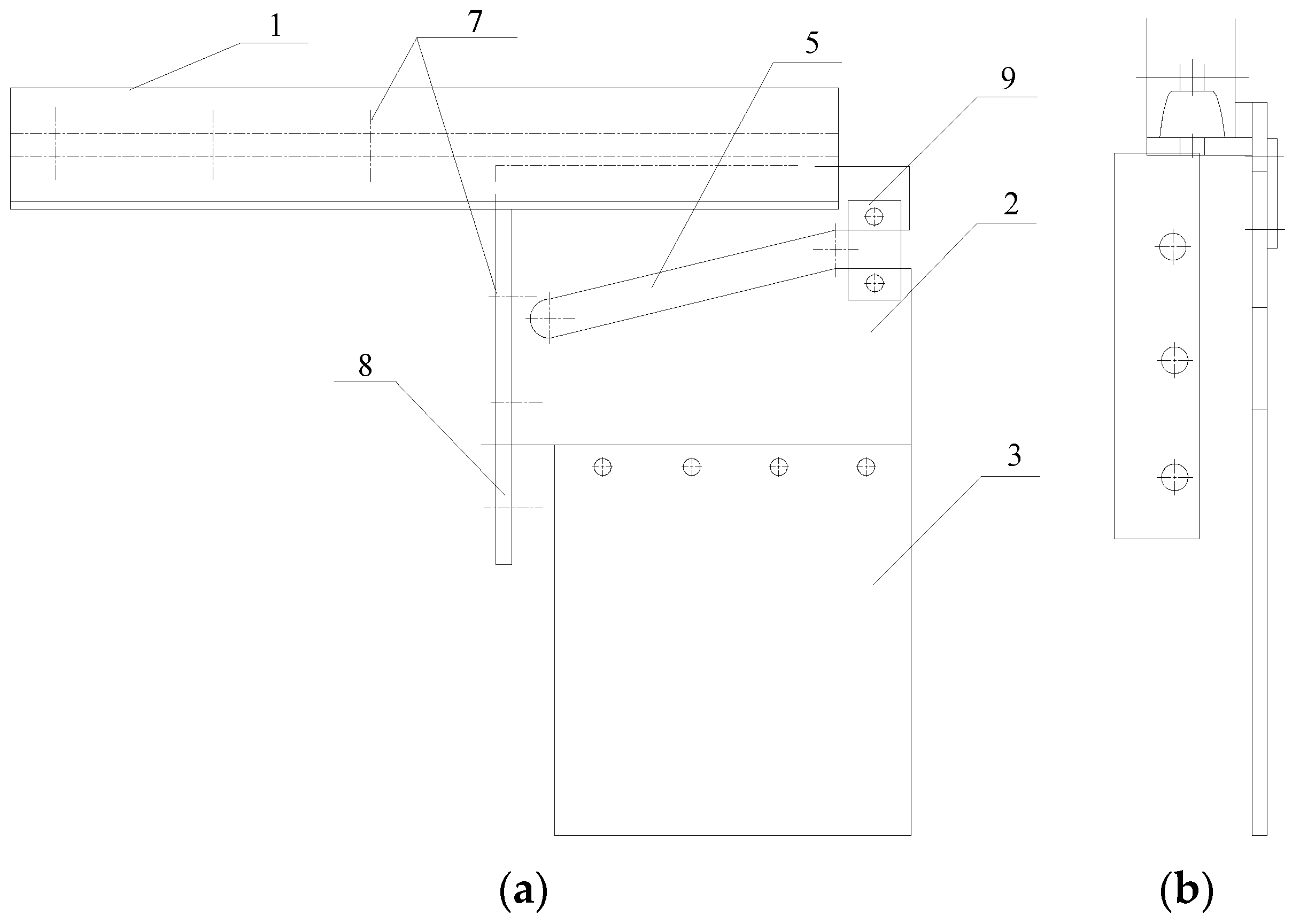
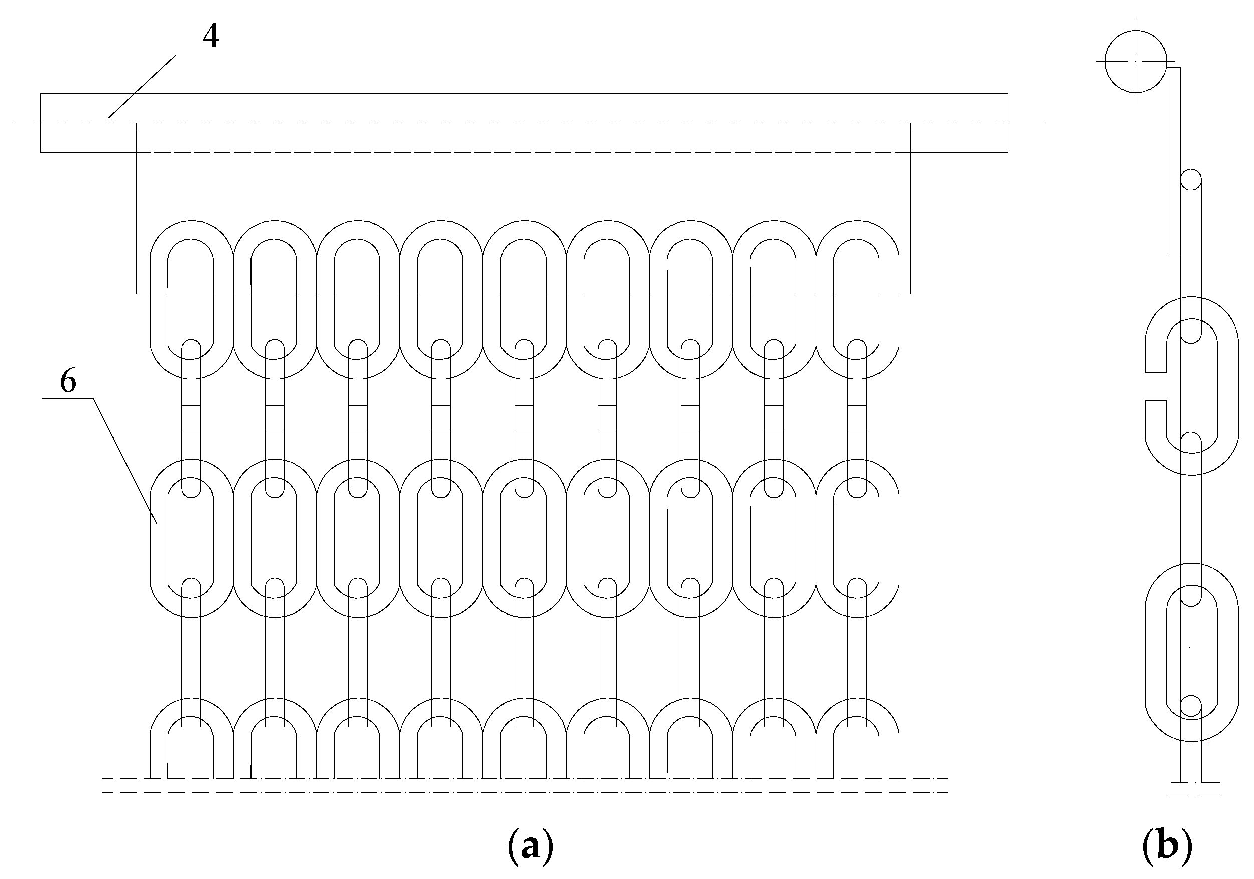
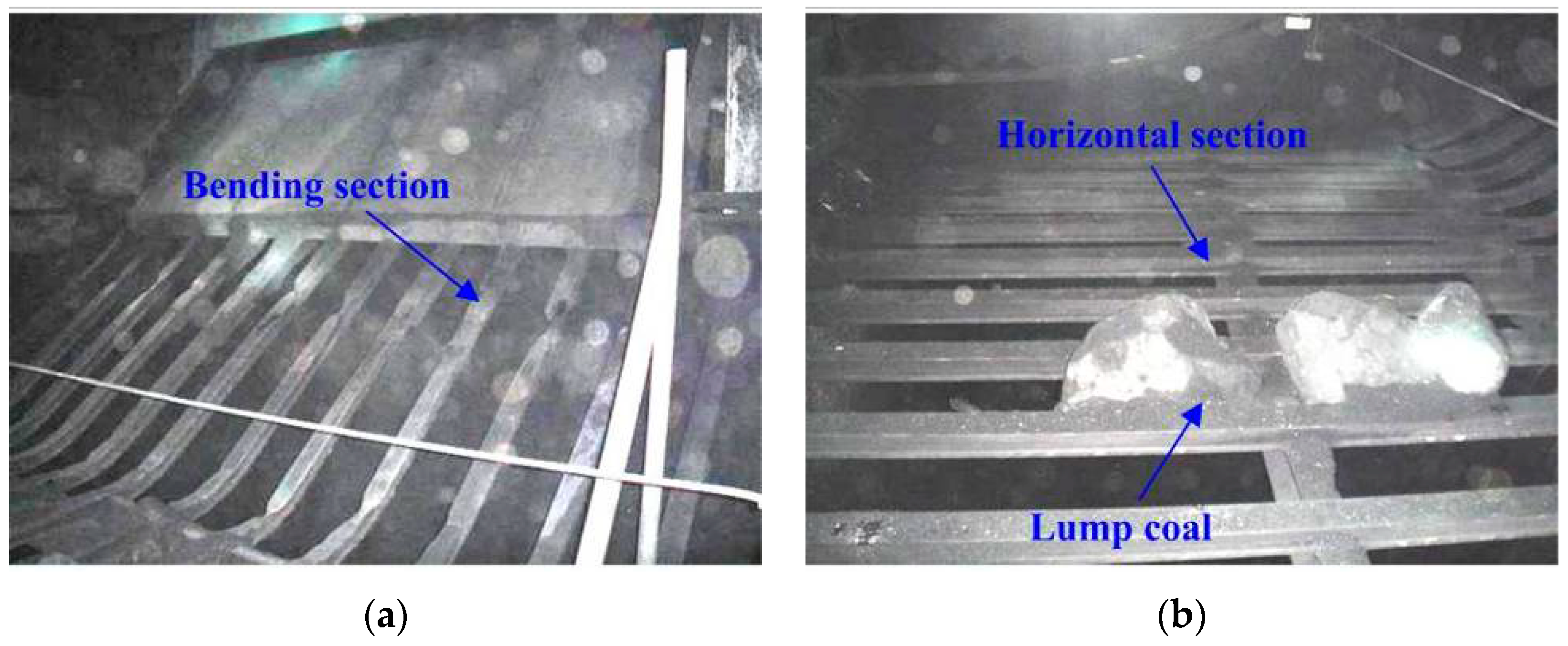
4.2. Reconstructions of Coalface End Transloading

Because of the large height difference (1.2–1.5 m) between the transloader end and the extensible belt conveyer, lumps falling from the transloader gain a large amount of speed causing violent collisions between the lumps and the conveyer surface. As a result, the overall LCPR is reduced in this process. To solve this, an additional buffer unit was installed at the transloader exit to lessen the collisions between the lumps and the conveyer, so as to reduce lump fragmentation by 4.7%.
The basic configurations of the buffer unit are shown in Figure 7. As viewed, the buffer unit mainly consists of side protecting plate components (Figure 8) and buffer axis components (Figure 9). Symmetrical side protecting plates were attached to the spill plates at the sides of the transloader. Components of the side protecting plate included a fixed flange beam, fixed side protecting plate, movable side protecting plate, fixed bolt, connection plate, and damper. The components of the buffer axis included a buffer axis, connection plate, buffer chain, and split ring.
Figure 7. Basic configuration of the buffer unit: 1, fixed flange beam; 2, fixed side protecting plate; 3, movable side protecting plate; 4, buffer axis; 5, guide slot; 6, buffer chain; 7, fixed bolt; 8, connection plate; 9, damper; 10, extensible belt conveyor.
Minerals 05 00533 g007
Figure 8. Schematic illustration of a side protecting plate: (a) front view; (b) side view.
Minerals 05 00533 g008
Figure 9. Schematic illustration of a buffer axis: (a) front view; (b) side view.
Minerals 05 00533 g009
The buffer axis and chains were placed at the exit of the transloader to set up a semi-confined space with the side protecting plates. As a result, the lumps were converged in the center part of the conveyer belt and decelerated, which result in reduced collisions with the conveyer belt. In case of a sudden increase in impacts on the buffer axis, it moved upwards along the guide grooves on the fixed side protecting plates to avoid severe damage to the unit’s components. Once the impacts were balanced by gravity, the buffer axis stayed in place. Unlike buffer teeth, the buffer axis actively responded to varying impacts and the lump speeds were kept without severe damage to the buffer unit. A fixed protecting plate and movable protecting plate replaced the transloader folding plate so that the plate length could be adjusted according to variations in the roadway floor.

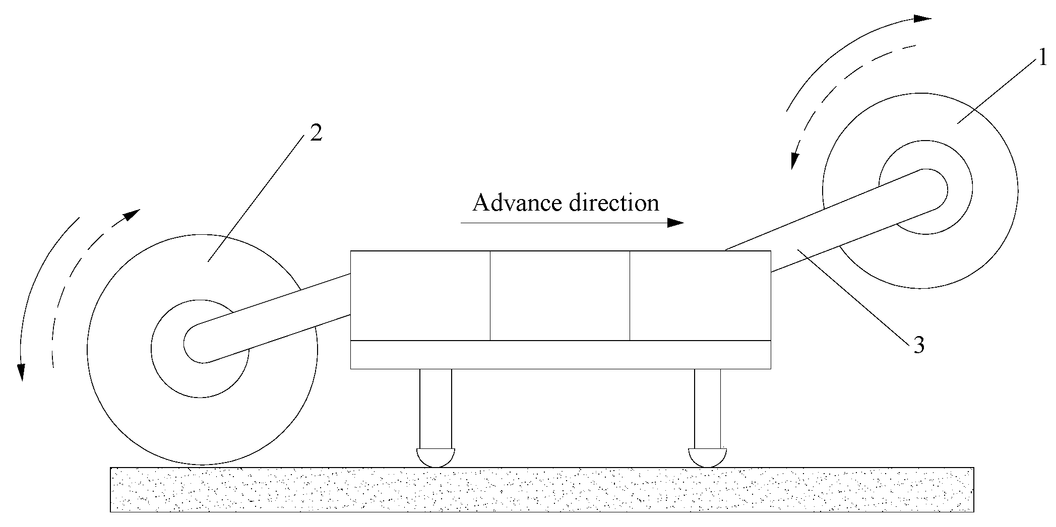
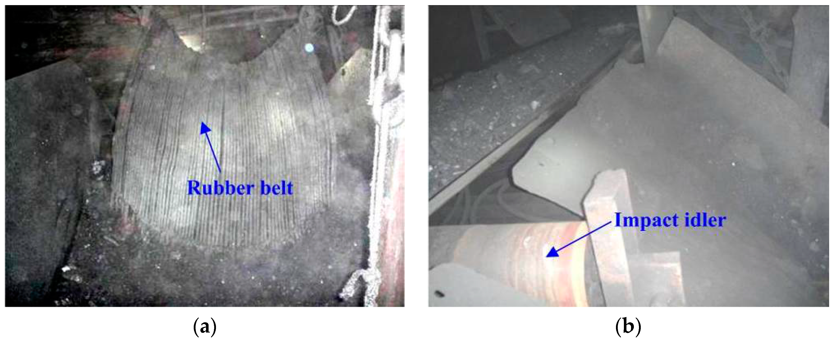
4.3. Applications of Wheel Crusher

In practical situations, large anthracite lumps mined from the coalface are pulverized by a coalface crusher connected to the transloader. In this process, conventional crushers (e.g., jaw crushers and hammer crushers) rely on compressive forces to crush the lumps. Nevertheless, cracks are formed in the lumps as the loading area of lumps is large. Meanwhile, their mechanical strengths degrade after compression. As a result, the lumps become extremely small and may be pulverized into powder in consecutive processes, and then reduce the LCPR of the anthracite. To avoid it, a Wheel Crusher (PLM 1000, ZMJ Company, Zhengzhou, China) that works well with the coalface end transloader is applied in XCM.
Specifically designed for domestic coal mines, this wheel crusher consists of a pulley, crushing chamber, unloading chamber, crushing axis components, and dust curtains (Figure 10) [36]. The crusher is connected to the transloader at both ends by connection holes. An additional joint is designed at its loading end so that a rigid connection between the crusher and the transloader could be established.
Conventionally, coal shows an average lump size below 100 mm after crushing, with 84% having a diameter no larger than 100 mm and 30% being of fine grade. As a result of crushing, the overall LCPR is reduced by 5%. By using the wheel crusher proposed in this study, the LCPR loss was reduced by only 2%. According to market surveys and customer feedback, this was achieved by optimizing the gear and crusher exit diameter (200–400 mm).
Figure 10. PLM 1000 Wheel Crusher: (a) left front view; (b) right front view.
Minerals 05 00533 g010

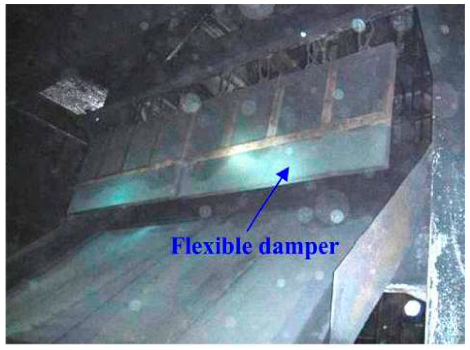
4.4. Adjustments in Transport Systems

Before being stored in underground bunkers, crushed raw coal is transported over a long distance and transloaded several times. Because of the long transport distance and the height differences in overlapping sections, the lumps fall a large distance at transloading points, resulting in lump fragmentation and reduced LCPR. The LCPR loss at each transloading point is estimated to be 0.5%. To mitigate this loss, the following adjustments were made to optimize the transport systems: (1) The roadway layout was improved so that the number of transloading points and height differences was lessened; (2) the height of overlapping sections of transloading points was reduced so that the falling heights of the lumps would be less than 0.5 m; (3) the steel wire mesh and flakes were replaced with a buffer device at transloading points (Figure 11).
Figure 11. Buffer device: (a) rubber belt; (b) impact idler.
Minerals 05 00533 g011

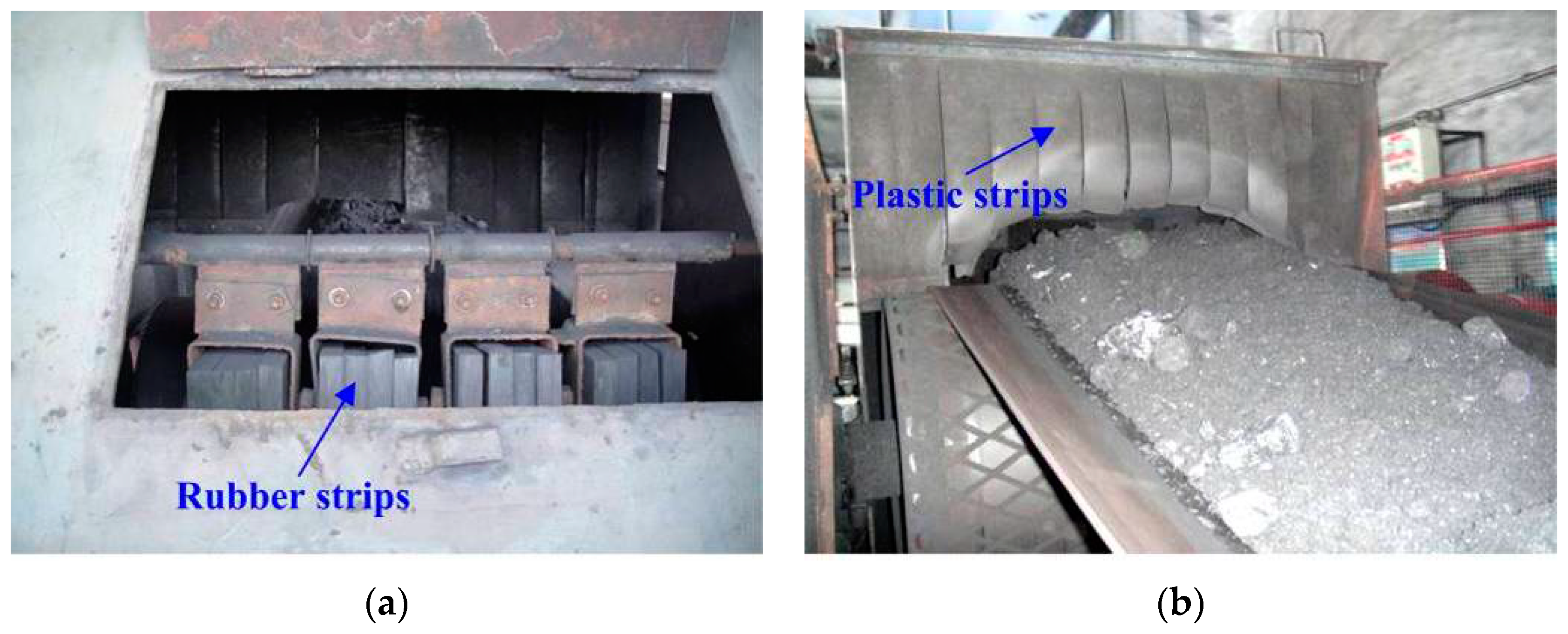
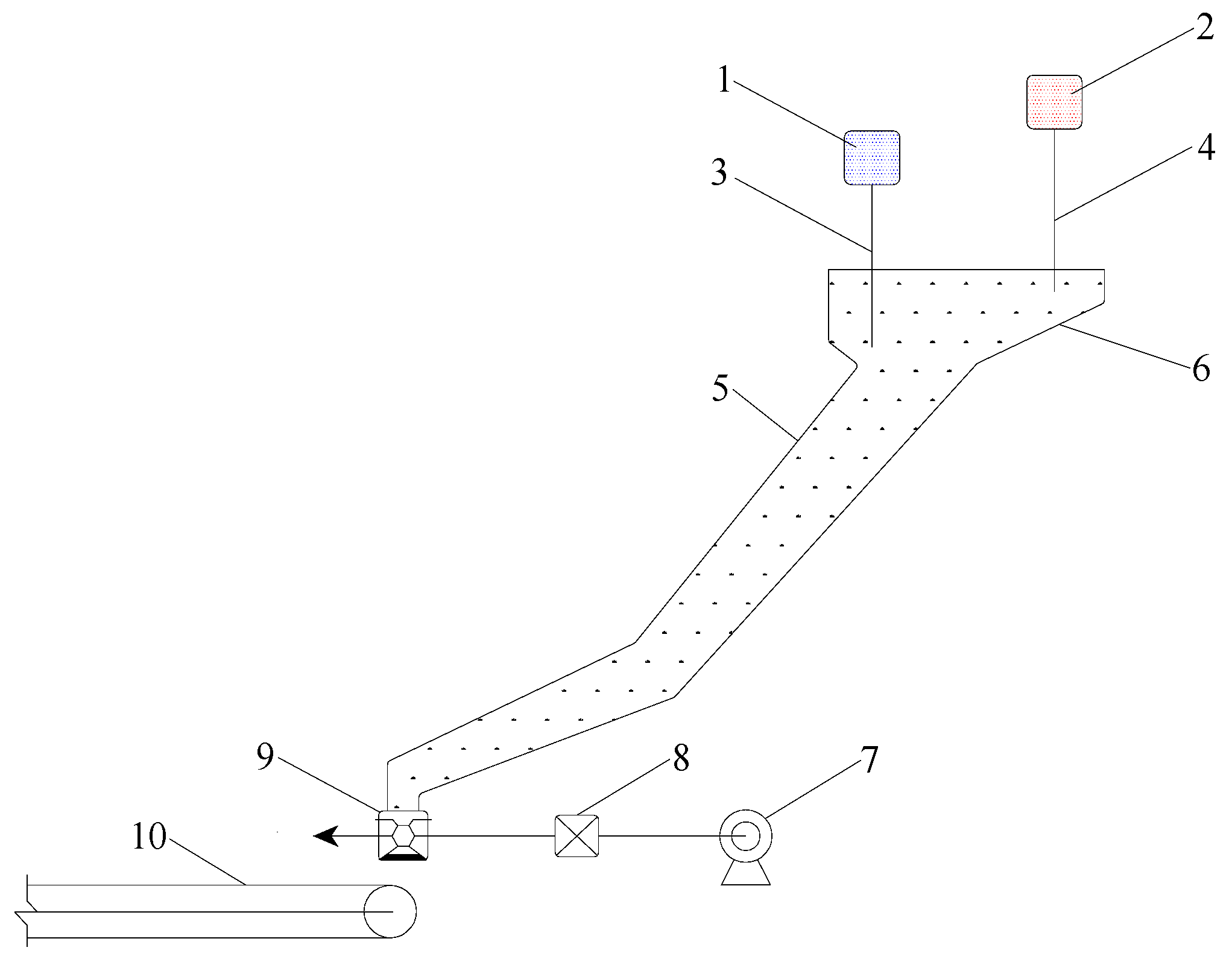
4.5. Optimizations of Underground Storage

As a key component of the coal production system, underground bunkers show significantly varying stock levels, resulting in unpredictable falling heights of the lumps. Collisions in the falling process caused great losses of lumps. Statistics revealed that the losses of LCPR in this process were as high as 6%–12% [37,38]. Therefore, it was essential and urgent to reduce the lump coal loss by improving the design of underground bunkers.
Designed bunker height of XCM was 28 m, which exceeded the optimized value for bunker bottom protection and lump preservation. To mitigate this issue, spiral bunkers are sometimes used. However, because construction and maintenance of spiral bunkers require significantly increasing costs and time, a novel bunker design was proposed. Specifically, the cross-section of the bunker was designed to be circular and permanently supported with anchor rod/anchor mesh/concrete (concrete support thickness is 0.4 m). Hanging spiral chutes were installed on the outside wall of the bunker and the junctions of these chutes were processed to strengthen its resistance to corrosion, rust, and wear. As a result, the final speed of the lumps was reduced and their collisions with the bunker were lessened, indicating that the LCPR was enhanced and damages to the bunker were reduced. Additionally, bunker blockings were also lessened. Practical applications revealed that the LCPR of bunkers equipped with spiral chutes increased by 30%.
The application of hanging spiral chutes had a significant effect on the LCPR. However, in the coal dumping process, it is difficult for operators to make reasonable decisions based purely on visual observations, resulting in over-dumping. As a result, the LCPR is reduced to a higher extent than expected in this process. To mitigate this issue, a stock level monitoring system (Figure 12) was installed at the bunker opening to promote the dumping process. In this way, both underground and ground operators can accurately control the bunker level. Additionally, an alarm is triggered once the stock level is below a prescribed value (17 m in this case) so that over-dumping would be prevented.
Figure 12. Bunker stock level monitoring system: (a) bunker opening; (b) sensor layout.
Minerals 05 00533 g012

4.6. Improvements to the Main Shaft Skip Unloading Processes

The main shaft is regarded as the core of a coal mine production system. In large and medium-sized mines, coal lifting is carried out at the main shaft with a skip. The raw coal is then lifted to the ground by the shaft skip and transloaded to the conveyer on the ground. Because of production rate needs, transloading rates are kept at a high level [39,40], resulting in violent collisions between the lumps and wellhead bunker walls. Therefore, a buffer chute (Figure 13), a flexible damper (Figure 14) and interval blocking units (Figure 15) were installed at the transloading sections to relieve the collisions and reduce lump loss of about 15%.
Figure 13. Buffer chute.
Minerals 05 00533 g013
Figure 14. Flexible damper.
Minerals 05 00533 g014
Figure 15. Interval blocking units: (a) bending section; (b) horizontal section.
Minerals 05 00533 g015

4.7. Fragmentation-Prevention in Washing Processes

According to previous studies, fragmentation in washing process contributes significantly to the overall lump loss [41,42]. To improve the washing process and overall LCPR, measures such as process flow optimization, screening, transloading modifications, and storage adjustments were used.
In cases where the screening plant is under maintenance, raw coal from the shaft is immediately transloaded to the storage. To avoid this, a heavy media separator for lumps is commonly used. In XCM, a +25 mm heavy media bevel wheel for lumps, a 0.5–25 mm heavy media cyclone for fines, and a −0.5 mm flotation slime unit was integrated and used. However, lump fragmentations resulting from high-speed rotation in the pumps, squeezing in the pipes, and collisions in heavy media cyclones were observed. Therefore, the sieve size was reduced from 25 to 13 mm so that lumps over 13 mm were injected into the heavy media bevel wheel separator. In this way, the LCPR was increased by 5.4%.
In the washing, and particularly the screening and transloading processes, lumps gain much energy while being relatively brittle. As a result, significant lump fragmentation occurs. To mitigate this issue, several measures were adopted: (1) A cushion was placed on the feeding chute of the sizing sieve to decelerate fast-moving lumps entering the sieve and reduce lump loss about 5.8%. (2) The front end chute of the medium-removing sieve was adapted to decelerate the falling lumps. Specifically, the chute angle was optimized and buffer plates were placed inside the chute. In this way, the traveling times of lumps in the chute were increased, resulting in a collection of coal. (3) Height differences at various transloading points were reduced. For those with height differences larger than 500 mm, buffer systems (rubber and plastic strips) were installed to reduce lump fragmentation as shown in Figure 16.
Figure 16. The buffer systems at transloading points: (a) rubber strips; (b) plastic strips.
Minerals 05 00533 g016
A fragmentation-prevention system (LKK-1, Figure 17) was installed in the bunker to mitigate lump fragmentation in the storage process. The coal lumps dropped into the chute after being processed through the sizing screens. The impeller coal feeder at the coal chute exit monitored and properly adjusted the fall of the screened lumps into the surge bunker so that the stock level of the bunker was kept at suitable levels.
Figure 17. LKK-1 fragmentation-prevention system: 1, signal relay of low stock level; 2, signal relay of high stock level; 3, electrode of low stock level; 4, electrode of high stock level; 5, coal chute; 6, surge bunker; 7, electromotor; 8, gearbox; 9, impeller coal feeder; 10, main conveyor.
Minerals 05 00533 g017

4.8. Fragmentation-Prevention in Railway Wagon Loading Processes

To overcome the limits of the conventional wagon loading processes, a novel fragmentation-prevention system was designed (Figure 18). This system consisted of a feeder, belt conveyer, and a chute stock level control unit. The feeder was placed on top of the belt conveyer and a storage hopper between the conveyer and the chute was incorporated. A stock level control unit consisting of a sensor and display was installed at the hopper entrance. The hopper exit was connected with the buffer chute and a gravity-controlling valve was installed at the chute exit, which was on top of the railway wagon. This fragmentation-prevention system presented distinct advantages. First, the hopper acted as a buffer unit and the falling heights of the lumps were kept within a suitable range by controlling the valve. Consequently, both noise and lump loss was reduced by 9.2%. This system is also expected to adapt coal lumps of various sizes, demonstrating great potential for industrial applications. Another noteworthy benefit of this system is that it is highly automatic and few operators are needed, which can greatly reduce working costs.
Figure 18. Railway wagon loading processes: (a) conventional loading system; (b) fragmentation-prevention loading system; 1, feeder; 2, belt conveyor; 3, chute; 4, railway wagon; 5, display of stock level; 6, sensor of stock level; 7, storage hopper; 8, winch; 9, valve.
Minerals 05 00533 g018

5. Economic Benefits

The application of the techniques and optimization processes developed in this study significantly improved the quality of the coal products and increased the anthracite yield, and finally increase profits of the coal mine. As shown in Table 2, an increase of 12 million CNY (113,851,993 × 10.54% = 12,000,000) per year was viewed from the increased LCPR alone.
Table 2. Quantity and quality situation of coal products in 2009.
MonthsRaw Coal Quantity (t)LCPR (%)Ash Content (%)Moisture Content (%)Calorific Value (kcal·kg−1)Incomes (CNY)
Contents
2009January155,73620.6510.104.96399-
February151,80822.219.855.16449-
March171,13821.089.904.96369-
April168,36919.2210.214.86193-
May168,63123.059.795.45960-
June162,73521.7412.115.26072-
July160,83819.3111.104.86131-
August159,73719.1910.265.25820-
September167,61020.8710.645.35651-
October157,84722.349.894.96057-
November153,85619.989.715.25848-
December177,51123.6910.365.45943-
Indexes of 20091,955,81621.1110.335.096074586,744,800
Indexes of 20081,681,68010.5719.466.055876472,892,807
Difference values274,13610.54-9.13-0.96198113,851,993

6. Conclusions

(1)
Based on the analysis of the cutting thickness of the shearer drums, the influence factors have been understood, including traction speed, drum rotating speed, arrangement of cutting picks, and the number of helical blades.
(2)
For optimized shearer performance in XCM, the following parameters should be employed: traction speed of 4–5 m/min, drum rotating speed of 35 r/min (initial design speed is 42 r/min), and 30 cutting picks (initial design number is 36). Additionally, the pick length was increased while the pick density was decreased. Moreover, a rear-front one-way cutting approach was used in the mining process, and the mining height and roof supporting intensity were reduced accordingly. A combination of LPMB and FMM was also applied.
(3)
Based on the principles of lump fragmentation, the coalface end transloading, coalface crushing, transport systems, underground storage, and main shaft skip unloading processes were all improved. Fragmentation-prevention techniques were also applied in the washing and wagon loading processes. As a result, fragmentation of the lump coal was obviously reduced. The LCPR was maintained at a high level, and a great increase in annual profits was achieved.
(4)
In order to widely and confidently use the parameters and techniques determined in this study, some research directions should be required in future studies such as more on-site measurements of LCPR, laboratory analysis of mechanical mechanisms for coal fragmentation, and techniques for high-quality anthracite production of open-pit mining.

Acknowledgments

The research is financially supported by the National Basic Research Program of China (No. 2015CB251600), the National Natural Science Foundation of China (No. 51404254), the China Postdoctoral Science Foundation (Nos. 2014M560465 and 2015T80604), the Jiangsu Planned Projects for Postdoctoral Research Funds (No. 1302050B) and the Fundamental Research Funds for the Central Universities (No. 2013QNB24). We wish to thank the XCM for supporting to conduct this important study, as well as Rong Zhou from YCPLC for the assistance of data collection. Special thanks are given to Jie-qing Yu from the China University of Mining & Technology, for his assistance with making illustrations, and Cheng-guo Zhang from the University of New South Wales, Australia, for his language assistance. The authors are also grateful to the two anonymous reviewers for their constructive comments and helpful recommendations.

Author Contributions

All the authors contributed to publishing this paper. Wei Zhang performed the technological development and prepared and edited the manuscript. Dong-sheng Zhang revised and reviewed the manuscript. Hong-zhi Wang and Ji-xin Cheng partially participated in the literature research and data processing during the research process.

Conflicts of Interest

The authors declare no conflict of interest.

Abbreviations

YMA
Yongxia Mining Area
XCM
Xinqiao Coal Mine
LCPR
Lump coal production rate
CBT
Cardox Blasting Technique
YCPLC
Yongcheng Coal & Power Company Limited
NSP
North Second Panel
LPMB
Loose presplitting millisecond blasting
FMM
Fully-mechanized mining

References

  1. Guo, J.Q.; Kang, T.H.; Kang, J.T.; Zhao, G.F.; Huang, Z.M. Effect of the lump size on methane desorption from anthracite. J. Nat. Gas Sci. Eng. 2014, 20, 337–346. [Google Scholar] [CrossRef]
  2. Huang, B.X.; Wang, Y.Z.; Cao, S.G. Cavability control by hydraulic fracturing for top coal caving in hard thick coal seams. Int. J. Rock Mech. Min. Sci. 2015, 74, 45–57. [Google Scholar] [CrossRef]
  3. Yarushina, V.M.; Bercovici, D.; Oristaglio, M.L. Rock deformation models and fluid leak-off in hydraulic fracturing. Geophys. J. Int. 2013, 194, 1514–1526. [Google Scholar] [CrossRef]
  4. Pang, L.; Hosseini, A.; Hussein, H.M.; Deiab, I.; Kishawy, H.A. Application of a new thick zone model to the cutting mechanics during end-milling. Int. J. Mech. Sci. 2015, 96–97, 91–100. [Google Scholar] [CrossRef]
  5. Somanchi, S.; Kecojevic, V.J.; Bise, C.J. Analysis of force variance for a continuous miner drum using the Design of Experiments method. Int. J. Min. Reclam. Environ. 2006, 20, 111–126. [Google Scholar] [CrossRef]
  6. Liu, X.H.; Liu, S.Y.; Tang, P. Coal fragment size model in cutting process. Powder Technol. 2015, 272, 282–289. [Google Scholar] [CrossRef]
  7. Jiang, H.X.; Du, C.L.; Liu, S.Y.; Gao, K.D. Nonlinear dynamic characteristics of load time series in rock cutting. J. Vibroeng. 2014, 16, 292–302. [Google Scholar]
  8. Saurabh, D.; Somnath, C.; Sergej, H. Investigation into coal fragmentation analysis by using conical pick. Procedia Mater. Sci. 2014, 5, 2411–2417. [Google Scholar]
  9. Vidanovic, N.; Ognjanovic, S.; Ilincic, N.; Ilic, N.; Tokalic, R. Application of unconventional methods of underground premises construction in coal mines. Tech. Technol. Educ. Manag. 2011, 6, 861–865. [Google Scholar]
  10. Lai, X.P.; Shan, P.F.; Cao, J.T.; Sun, H.; Suo, Z.Y.; Cui, F. Hybrid assessment of pre-blasting weakening to horizontal section top coal caving (HSTCC) in steep and thick seams. Int. J. Min. Sci. Technol. 2014, 24, 31–37. [Google Scholar] [CrossRef]
  11. Reddy, S.K.; Sastry, V.R. Gallery monitoring in blasting gallery panel during depillaring—A case study. J. Mines Metals Fuels 2013, 61, 257–260. [Google Scholar]
  12. Satyanarayana, I.; Budi, G.; Deb, D. Strata behaviour during depillaring in Blasting Gallery panel by field instrumentation and numerical study. Arab. J. Geosci. 2015, 8, 6931–6947. [Google Scholar] [CrossRef]
  13. Wang, F.T.; Tu, S.H.; Yuan, Y.; Feng, Y.F.; Chen, F.; Tu, H.S. Deep-hole pre-split blasting mechanism and its application for controlled roof caving in shallow depth seams. Int. J. Rock Mech. Min. Sci. 2013, 64, 112–121. [Google Scholar] [CrossRef]
  14. Zhao, T.B.; Zhang, Z.Y.; Tan, Y.L.; Shi, C.Z.; Wei, P.; Li, Q. An innovative approach to thin coal seam mining of complex geological conditions by pressure regulation. Int. J. Rock Mech. Min. Sci. 2014, 71, 51–52. [Google Scholar] [CrossRef]
  15. Song, J.; Lian, Q.W. The relation between coal lump rate and cutting method of miner. Shanxi Coal 2003, 23, 20–21. (In Chinese) [Google Scholar]
  16. Zhang, L.M. The current situation and developing trend of extremely thin coal seam mining of China. Appl. Mech. Mater. 2013, 295, 2918–2923. [Google Scholar] [CrossRef]
  17. Li, Z.Q.; Oyediran, I.A.; Tang, C.; Hu, R.L.; Zhou, Y.X. FEM application to loess slope excavation and support: Case study of Dong Loutian coal bunker, Shuozhou, China. Bull. Eng. Geol. Environ. 2014, 73, 1013–1023. [Google Scholar] [CrossRef]
  18. Kozan, E.; Liu, S.Q. A demand-responsive decision support system for coal transportation. Decis. Support Syst. 2012, 54, 665–680. [Google Scholar] [CrossRef]
  19. Zhang, L.; Zhu, G.Q.; Zhang, G.W.; Han, R.S. Performance-based fire design of air-supported membrane coal storage shed. Procedia Eng. 2013, 52, 593–601. [Google Scholar] [CrossRef]
  20. Wang, X.W.; Qin, Y.; Tian, Y.K.; Yang, X.Y.; Yang, Z.J. Analysis on flow features of bulk coal during coal unloading period based on EDEM. Coal Sci. Technol. 2015, 43, 130–134. (In Chinese) [Google Scholar]
  21. Lv, H.L.; Ma, Y.; Zhou, S.C.; Liu, K. Case study on the deterioration and collapse mechanism and curing technique of RC coal bunkers. Procedia Earth Planet. Sci. 2009, 1, 606–611. [Google Scholar] [CrossRef]
  22. Liu, S.Q.; Kozan, E. Optimising a coal rail network under capacity constraints. Flex. Serv. Manuf. J. 2011, 23, 90–110. [Google Scholar] [CrossRef]
  23. Singh, G.; Sier, D.; Ernst, A.T.; Gavriliouk, O.; Oyston, R.; Giles, T.; Welgama, P. Mixed integer programming model for long term capacity expansion planning: A case study from The Hunter Valley Coal Chain. Eur. J. Oper. Res. 2012, 220, 210–224. [Google Scholar] [CrossRef]
  24. Wang, Y. Using the limiting transferring device to increase the lump coal rate of anthracite. Coal Process. Compr. Util. 2008, 3, 10–12. (In Chinese) [Google Scholar]
  25. Xie, W.N.; He, Y.Q.; Zhu, X.N.; Ge, L.H.; Huang, Y.J.; Wang, H.F. Liberation characteristics of coal middlings comminuted by jaw crusher and ball mill. Int. J. Min. Sci. Technol. 2013, 23, 669–674. [Google Scholar] [CrossRef]
  26. Chen, J.; Chu, K.W.; Zou, R.P.; Yu, A.B.; Vince, A. Prediction of the performance of dense medium cyclones in coal preparation. Miner. Eng. 2012, 31, 59–70. [Google Scholar] [CrossRef]
  27. Zeng, R.; Du, C.L.; Chen, R.J.; Wang, W.J. Reasonable location parameters of pick and nozzle in combined cutting system. J. Cent. South Univ. 2014, 21, 1067–1076. [Google Scholar] [CrossRef]
  28. Reid, A.W.; McAree, P.R.; Meehan, P.A.; Gurgenci, H. Longwall shearer cutting force estimation. J. Dyn. Syst. Meas. Control 2014, 136, 1–9. [Google Scholar] [CrossRef] [Green Version]
  29. Gao, H.B.; Yang, Z.J. Fluctuation analysis of thickness about roller shearer. Coal Mine Mach. 2013, 34, 106–108. (In Chinese) [Google Scholar]
  30. Mazurkiewicz, D. Empirical and analytical models of cutting process of rocks. J. Min. Sci. 2000, 36, 481–486. [Google Scholar] [CrossRef]
  31. Liao, X.; Zhang, J.; Feng, T.; Li, P. Intensity nonlinear analysis of central groove of coal shearer under limiting conditions. J. Southeast Univ. 2014, 44, 531–537. (In Chinese) [Google Scholar]
  32. Bilgin, N.; Balci, C.; Copur, H.; Tumac, D.; Avunduk, E. Cuttability of coal from the Soma coalfield in Turkey. Int. J. Rock Mech. Min. Sci. 2015, 73, 123–129. [Google Scholar] [CrossRef]
  33. Senneca, O.; Urciuolo, M.; Chirone, R. A semidetailed model of primary fragmentation of coal. Fuel 2013, 104, 253–261. [Google Scholar] [CrossRef]
  34. Zhou, Y.D.; Liu, Y.L.; Tang, X.W.; Cao, S.Q.; Chi, C.J. Numerical investigation into the fragmentation efficiency of one coal prism in a roller pulveriser: Homogeneous approach. Miner. Eng. 2014, 63, 25–34. [Google Scholar] [CrossRef]
  35. Thorpe, J.F. On the momentum theorem for a continuous system of variable mass. Am. J. Phys. 1962, 30, 637–640. [Google Scholar] [CrossRef]
  36. Hao, Q.S. Increase setting in use of middle digging coalface by modifying crusher and optimizing coal drift. Northwest Coal 2008, 6, 56–57. (In Chinese) [Google Scholar]
  37. Yu, T.F. Design and application of spiral chute in preventing lump coal crushing. Coal Mine Mach. 2014, 35, 207–209. (In Chinese) [Google Scholar]
  38. Deng, J.J.; Huang, J.Y.; Kuang, Y.L. Design of integrated manufacturing system of coal preparation plant based on multi-agent. Procedia Earth Planet. Sci. 2009, 1, 713–717. [Google Scholar] [CrossRef]
  39. Kou, B.F.; Liu, Q.Z.; Liu, C.Y.; Liang, Q. Characteristic research on the transverse vibrations of wire rope during the operation of mine flexible hoisting system. J. China Coal Soc. 2015, 40, 1194–1198. (In Chinese) [Google Scholar]
  40. Peterka, P.; Kresak, J.; Kropuch, S.; Fedorko, G.; Molnar, V.; Vojtko, M. Failure analysis of hoisting steel wire rope. Eng. Fail. Anal. 2014, 45, 96–105. [Google Scholar] [CrossRef]
  41. Wang, Z.G.; Kuang, Y.L.; Deng, J.J.; Wang, G.H.; Ji, L. Research on the intelligent control of the dense medium separation process in coal preparation plant. Int. J. Miner. Process. 2015, 142, 46–50. [Google Scholar] [CrossRef]
  42. Noble, A.; Luttrell, G.H. A review of state-of-the-art processing operations in coal preparation. Eng. Fail. Anal. 2015, 25, 511–521. [Google Scholar] [CrossRef]

