Article

Temporal and Spatial Distribution of Respirable Dust After Blasting of Coal Roadway Driving Faces: A Case Study

1
College of Mining Engineering, Taiyuan University of Technology, Taiyuan 030024, China
2
Green Mining Engineering Technology Research Center of Shanxi Province, Taiyuan 030024, China
*
Author to whom correspondence should be addressed.
Minerals 2015, 5(4), 679-692; https://doi.org/10.3390/min5040517
Submission received: 20 August 2015 / Revised: 14 September 2015 / Accepted: 21 September 2015 / Published: 15 October 2015
(This article belongs to the Special Issue Advanced Underground Mine Ventilation and Monitoring Systems)

Abstract

:
Coal roadway driving is an important part of the underground mining system, and very common in Chinese coal mines. However, the high concentration of respirable dust produced in the blasting operation poses a great hazard to miners’ health as well as the underground environment. In this paper, based on the direct simulation Monte Carlo method, the gas–solid two-phase flow model of particle movement is established to study the respirable dust distribution in blasting driving face. The results show that there is an obvious vortex region in which airflow velocity is lower than that close to the roadway wall and driving face. After blasting, respirable dust in the front of the dust group jet from the driving face cannot be discharged timely, with the result that its concentration is higher than the critical value until it is expelled from the roadway, whereas respirable dust concentration at the back of the dust group is gradually diluted and exhibits an alternate thin dense phase distribution. Meanwhile, respirable dust concentration in the breathing zone is relatively higher than that at the top and bottom of roadway. The accuracy of numerical simulation results is verified by field measurements. The research results are helpful for further understanding the evolution of respirable dust distribution after blasting, and are good for providing guidance for efficient controlling of respirable dust and improving the working environment for underground miners.

1. Introduction

Coal, as one of the world’s three major energy sources, accounts for a huge proportion of the worldwide energy supply. Especially in China, coal, as a basic energy source, requires a large number of mines [1]. In the process of mining and tunneling, drilling and blasting are the most important methods of rock excavation and rock breaking, particularly in hard rock conditions [2,3]. Respirable dust at the high concentrations generated by the blasting operation pollutes the underground working environment heavily, and even leads to coal dust explosions, causing heavy casualties and huge economic losses [4]. Most seriously, miners are likely to be infected with pneumoconiosis, which is a lung disease that mainly results from breathing in respirable coal dust over a long period of time [5]. In China, more than 2.65 million miners are exposed to coal dust. New pneumoconiosis cases number 25,000 every year, of which 6000 cases die of coal dust [6]. Therefore, taking effective methods to suppress coal dust, especially to lower respirable dust concentration, has significant implications.
In order to control dust concentration, abundant methods such as water infusion [7], water spraying [8], chemical dust suppression agent [9,10], and negative pressure have been used. The analysis of the measures for dust control and prevention indicates that there are still obvious limitations among those extant methods affecting and restricting dust prevention and dust removal, as well as the efficiency of respirable dust removal [11,12]. The essential cause of these problems is a lack of knowledge about respirable dust distribution regularity, which often leads to unreasonable design for dust control and irrelevant disposal of dust control equipment [13]. Therefore, it is necessary to investigate the distribution regularity of respirable dust and take effective measures to reduce dust concentration in the underground workplace of coal mines [14,15].
According to obtainable comparisons, numerical simulation is a relatively useful method in the study of respirable dust distribution due to its high efficiency and low cost. Therefore, it has been widely used as the basic method for research on respirable dust distribution. Toraño et al. [16] presented a study of coal mine dust behavior in two auxiliary ventilation systems by computational fluid dynamics (CFD) models. Kurnia et al. [17] utilized the CFD approach to evaluate the various methods used for mitigating dust dispersion from the mining face and for ensuring safe level of dust concentration in the mine tunnel for safety of the operators. Wang et al. [18] conducted a study of the airflow and respirable dust flow behavior with 3D CFD modeling and predicted the air flow field around the crusher and transfer point above the underground bin and along the belt roadway. Zhang et al. [19] used the Fluent software to simulate dust’s migration law in the working face and determine its spatial distribution condition. Sa et al. [20] established a model of dust migration based on the theory of gas–solid two-phase flow and the characteristics of the cavern stope. The dust concentration of the cavern stope changes due to ventilation every 20 min after blasting and the dust trajectory in different wind speeds were simulated by Fluent software. However, these studies mainly concentrate on comprehensive mechanized heading face and the numerical method used does not consider the factor of inter-particle collision.
Given this, this paper uses Fluent software to calculate the continuous phase flow field and build a model independently for the movement of the discrete particle phase. Taking a blasting driving face in Wulan coal mine in China as the physical prototype, this paper researches the particle movement and diffusion characteristics in blasting driving faces. The numerical simulation results are verified by field measurements.

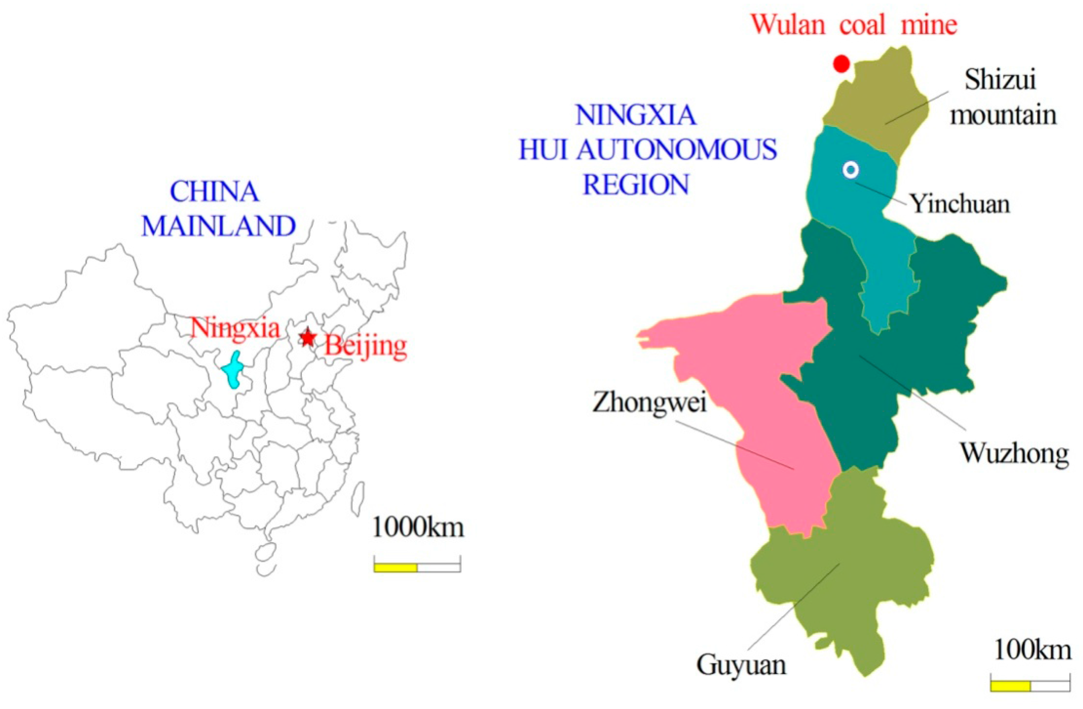
2. Research Background

Wulan coal mine is located in Ningxia Hui Autonomous Region, China (as shown in Figure 1). Stretching 5.3 km from south to north and measuring 3.04 km from east to west, Wulan coal field covers an area of 11.15 km2 and produces 1.85 million tons of coal annually. Coal dust from all seams in Wulan mine poses an explosion hazard; the explosive index of the coal dust is between 25.98%–32.44%. Driving faces of this mine are all blasting driving faces. Since the coal seam of Wulan mine is soft, blasting driving faces often produces a lot of coal dust floating in the air. The average dust concentration is 1500 mg/m3. Many miners working over a long period of time in such a high dust concentration contract pneumoconiosis. The main reason is that the temporal and spatial distribution pattern of respirable dust is not clear. Such unclear knowledge can lead to an unreasonable design for dust control systems and make dust control equipment irrelevant. Therefore, it is necessary to study the temporal and spatial distribution of dust distribution to provide a scientific basis for choosing reasonable parameters for a dust removal system after blasting so that coal workers’ pneumoconiosis can be prevented to a certain extent.
Figure 1. Location of Wulan coal mine.
Minerals 05 00517 g001

3. Mathematical Model of Gas–Solid Two-Phase Flow

3.1. Mathematical Model of Airflow Field

The Euler–Euler model has been adopted in three dimensions for describing the continuous gas phase in the roadway. Continuity equation and momentum equation of the gas phase can be written in the following forms, respectively [21]:
{ ( u j ) x j = 0 ( u i ) t + ( u i u j ) x j = 1 ρ g ( p x i + ( τ j i ) x j + ρ g g )
where u i and u j are the velocity, i, j = 1, 2, 3 are the x, y, and z directions, respectively, and τ j i is the turbulent stress tensor. For the whole computational domain, the particle volume concentration is very low. Even at the initial conditions, the particle volume concentration is only about 10−4%. So the impact of particle flow field can be ignored and the impact of flow field to particle phase only be considered.
τ j i = ( μ + μ t ) ( u j x i + u i x j ) 2 3 ρ g κ δ i j
where μ represents the dynamic viscosity, μt is the turbulent viscosity, κ stands for the turbulent Kinetic energy, and δij is the Kronecker constant.

3.2. Gas–Solid Two-Phase Interaction Models

The Euler–Lagrange model has been adopted for tracking and calculating the discrete particle phase, and collisions between particles are studied based on the direct simulation Monte Carlo method. Since the particle phase concentration is relatively low, the coupling effect between the two gas–solid-phases can be ignored and only the effect of gas phase on solid phase is considered [22].
As to the particle phase, the forces produced by the relative movement of particles and air flow, field forces, the forces generated by particle–particle interactions, and the forces generated by particle–wall interactions are mainly considered [23]. Similarly, the forces generated by the interactions of gas and particles are multiple, including drag force, Magnus force, Saffman force, false quality force, pressure gradient force, and Basset force. However, considering the needs of the research, this paper only takes drag force fd. and gravity force into consideration, ignoring all the other fluid forces.
f d = β ( v u )
where
β = 3 4 C D | v u | ρ ( 1 ε ) D p ε 2.7
C D = { 24 ( 1 + 0.15 Re 0.687 ) / Re Re 1000 0.43 Re > 1000
Re = D P | u r | / v
u r = u v
where u is the gas velocity, v is the solid phase velocity, Dp stands for the particle diameter, ε is the voidage, and p is the gas phase density.
The sample particle trajectory is tracked by using the direct simulation Monte Carlo model and the particle–particle collisions are determined through probability while considering the influence of particle rotation, which can be described as follows:
m 1 ( V 1 V 1 ( 0 ) ) = J
m 2 ( V 2 V 2 ( 0 ) ) = J
I 1 ( ω 1 ω 1 ( 0 ) ) = r 1 n × J
I 2 ( ω 2 ω 2 ( 0 ) ) = r 2 n × J
n G ( 0 ) | G c t ( 0 ) | < 2 7 1 f ( 1 + e )
V 1 = V 1 ( 0 ) ( n f t ) ( n G ( 0 ) ) ( 1 + e ) m 2 m 1 + m 2
V 2 = V 2 ( 0 ) + ( n f t ) ( n G ( 0 ) ) ( 1 + e ) m 1 m 1 + m 2
ω 1 = ω 1 ( 0 ) + 5 2 r 1 ( n G ( 0 ) ) ( n × t ) f ( 1 + e ) m 2 m 1 + m 2
ω 2 = ω 2 ( 0 ) + 5 2 r 2 ( n G ( 0 ) ) ( n × t ) f ( 1 + e ) m 1 m 1 + m 2
n G ( 0 ) | G c t ( 0 ) | < 2 7 1 f ( 1 + e )
V 1 = V 1 ( 0 ) [ ( 1 + e ) ( n G ( 0 ) ) n + 2 7 | G c t ( 0 ) | t ] m 2 m 1 + m 2
V 2 = V 2 ( 0 ) + [ ( 1 + e ) ( n G ( 0 ) ) n + 2 7 | G c t ( 0 ) | t ] m 1 m 1 + m 2
ω 1 = ω 1 ( 0 ) 5 7 r 1 | G c t ( 0 ) | ( n × t ) m 2 m 1 + m 2
ω 2 = ω 2 ( 0 ) 5 7 r 2 | G c t ( 0 ) | ( n × t ) m 1 m 1 + m 2
G ( 0 ) = V 1 ( 0 ) V 2 ( 0 )
G c t ( 0 ) = G ( 0 ) ( G ( 0 ) n ) n + r 1 ω 1 ( 0 ) × n + r 2 ω 2 ( 0 ) × n
t = G c t ( 0 ) | G c t ( 0 ) |
where m is the mass and V is the velocity, r refers to the particle radius. The subscripts 1 and 2 refer to the two particles and the superscript (0) refers to values before collisions. J is the impulse exerted on particle 1, which acts on particle 2 as the reaction, n is the normal unit vector directed from particle 1 to particle 2 at the moment of contact, f is the friction coefficient of Coulomb’s friction law, and e is the coefficient of restitution. G(0) is the relative velocity of the particle centers before collision, G c t ( 0 ) is the tangential component of the relative velocity G(0) of the contact point before collision, and t is the unit vector in the tangential direction. The roadway wall is seen as an infinite sphere and the particle–particle collision model is adopted to deal with the collision between particles and roadway wall.
The corresponding program development of multiphase flow is completed independently by using the above gas–solid two-phase flow mathematical model. The migration rule of respirable dust after blasting in blasting driving face can be calculated and studied.

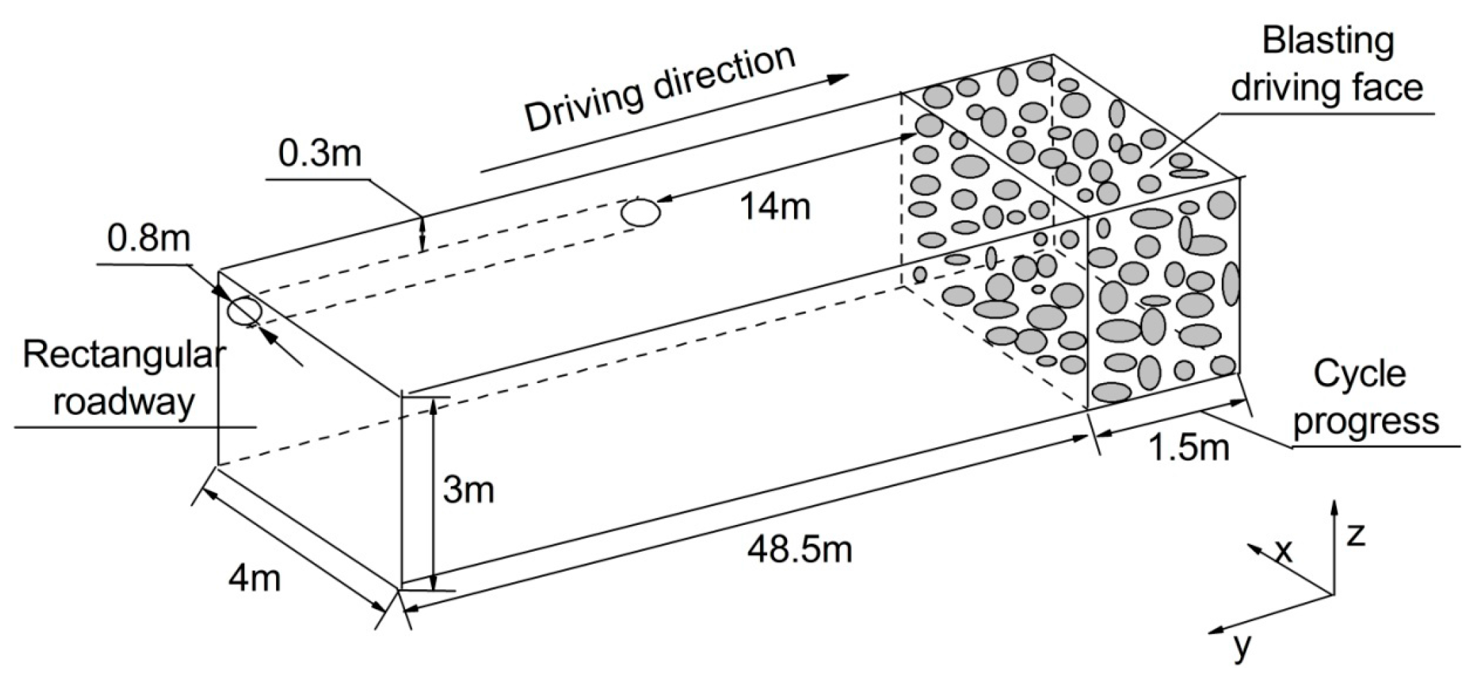
3.3. Establishment of Geometrical Model

This paper takes a blasting driving face in Wulan coal mine in China as the physical prototype, builds a geometric model, and sets related parameters. The rectangular roadway section is 4 m wide and 3 m high. The diameter of the ventilation duct is 0.8 m. The distance from the ventilation duct to the roof is 0.3 m and to the driving head-on before blasting is 14 m. The blasting cycle progress is 1.5 m (as shown in Figure 2). The air outlet velocity of ventilation duct is 10 m/s and respirable dust concentration near the driving face after blasting is 1500 mg/m3. Assume that the respirable dust of cycle progress jets is moved at a speed of 6 m/s, which is a normal operating condition when blasting coal roadway driving faces.
Figure 2. Geometric model of blasting driving roadway.
Minerals 05 00517 g002

3.4. Computational Conditions

The simulation parameters of the geometric model as well as its values are represented in Table 1.
Table 1. Calculation model parameters.
Simulation ParametersValue
Air viscosity (m2/s)0.000017894
Air density (kg/m3)1.225
Dust density (kg/m3)1500
Time step for particle (s)0.000025
Simulated particles flow time (s)180
Initial dust concentration (mg/m3)1500
Particle median diameter0.000055
Particle dispersion index2.95
Maximum particle diameter (μm)100
Minimum particle diameter (μm)0.1
Gas phase grid number530,000
Coefficient of restitution between particles0.8
Coefficient of restitution between particle and wall0.6
Friction coefficient between particles0.3
Average size of gas phase grid100 mm
Friction coefficient between particle and roadway wall0.4

4. Results and Discussion

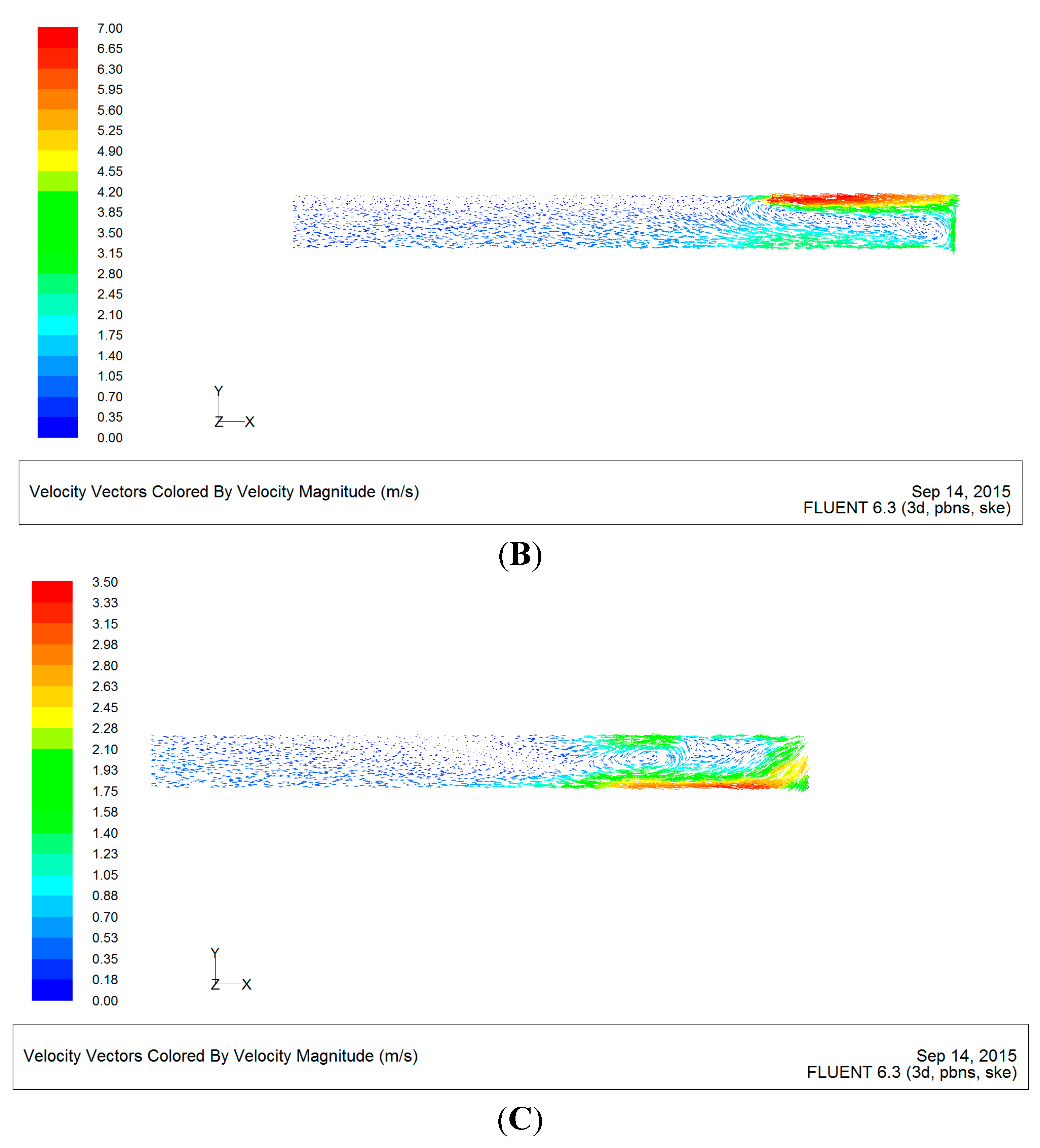
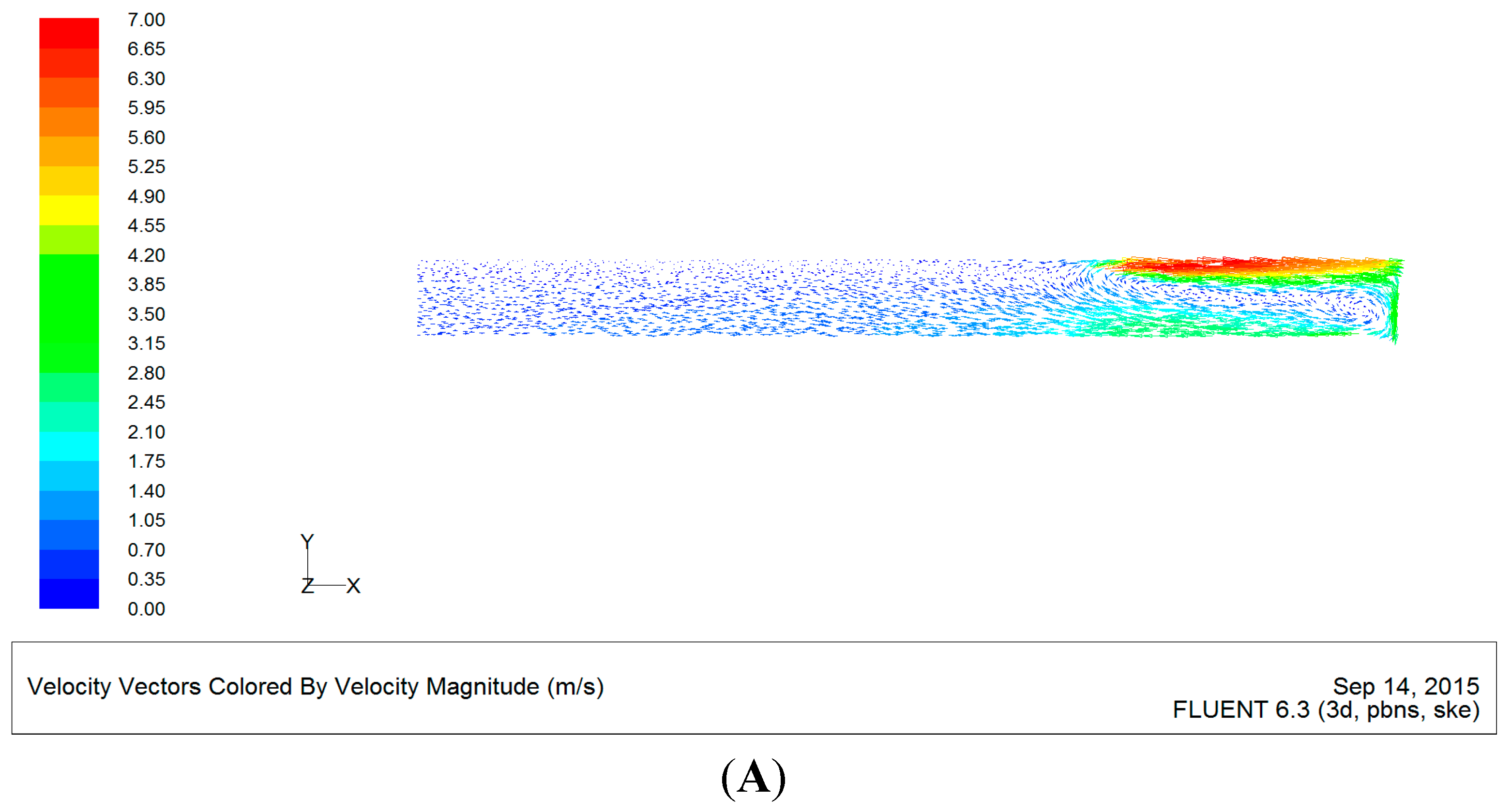
4.1. Airflow Field Distribution in the Roadway

In order to research the regularity of air flow field velocity distribution in blasting a driving coal roadway, this paper intercepts three cross sections at different heights in the roadway and Figure 3 shows the regularity of air flow field velocity distribution.
It can be found from Figure 3 that there exists an obvious vortex region at 25 m off the wind direction from the driving face. The velocity in the center of the vortex region is about 0.4 m/s, which is lower than the velocity close to the driving face and both sides of the roadway wall of the vortex region. At the region more than 25 m away from the driving face along the roadway, the velocity distribution in the roadway tends to be more uniform and stable, below 1.0 m/s. However, because of the effect of the friction between the roadway wall and air flow, the velocity in the center of the roadway is slightly higher than that near the roadway wall.
Figure 3. Air flow field velocity distribution at different heights. (A) H = 2.75 m; (B) H = 1.5 m; (C) H = 0.25 m.
Minerals 05 00517 g003aMinerals 05 00517 g003b

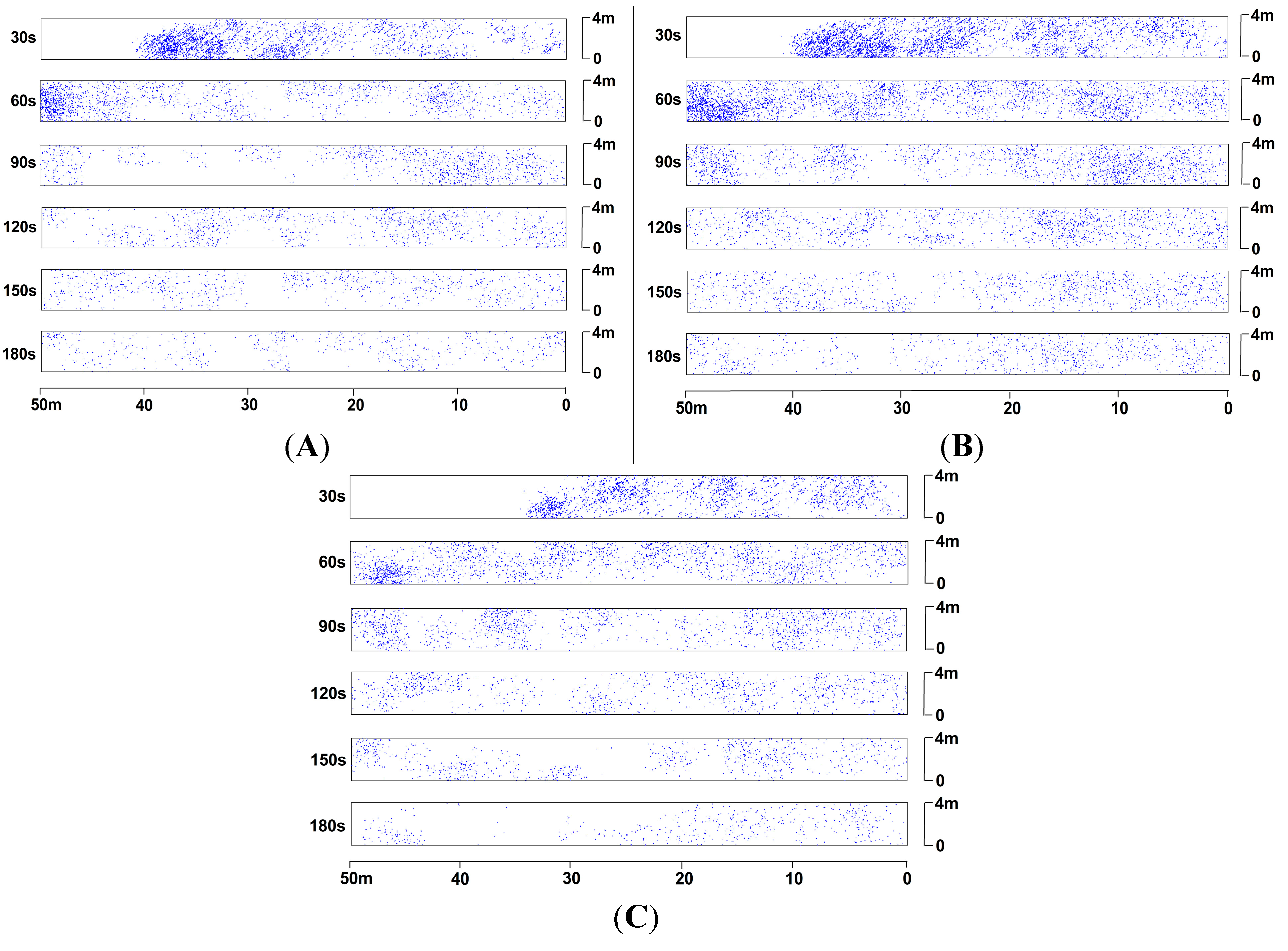
4.2. Temporal and Spatial Distribution Characteristics of Respirable Dust

In order to study the regularity of respirable dust distribution in blasting driving face, this research intercepts three cross- sections at different heights in a roadway. Figure 4 shows the regularity of respirable dust distribution on the whole.
As shown in Figure 4, a lot of dust enters into the roadway at a high speed under the action of the shock wave after blasting and gradually moves to the roadway outlet under the action of the air flow. Respirable dust is diluted from the back-end of the dust group to the front-end by air flow from ventilation ducts after blasting. However, due to the high initial jet velocity, the front-end respirable dust cannot be diluted in a timely manner, so the concentration in the front of the dust group stays at a high level until it is expelled from the roadway, whereas respirable dust at the back of the dust group is discharged under the entrainment effect of air flow.
As time goes on, the concentration of the respirable dust shows a gradual overall decrease and finally remains stable, exhibiting an alternate thin dense phase distribution in the roadway. The concentration of respirable dust in the vortex region, in which the velocity of air flow is low, is slightly higher than that in the surrounding areas. Obviously, the concentration of the respirable dust in the breathing zone is higher than that in the other cross sections in general. Therefore, much attention should be paid to strengthening the control of the respirable dust concentration in this area.
Figure 4. Temporal and spatial distribution characteristics of respirable dust at different heights. (A) H = 2.75 m; (B) H = 1.5 m; (C) H = 0.25 m.
Minerals 05 00517 g004
Figure 5, Figure 6 and Figure 7 represent the distribution of respirable dust concentration along the roadway at different heights. The China State Administration of Work Safety [24] enacted safety regulations in coal mines to provide respirable dust concentration limit values in coal mines for dust control in China, as shown in Table 2. According to Table 2, the free silica dioxide content of respirable dust in Wulan mine is between 10% and ~50%, and the maximum allowable concentration is 1 mg/m3.
Table 2. Respirable dust concentration limit values in coal mines.
Free Silica Dioxide Content of Respirable Dust (%)Maximum Allowable Concentration (mg/m3)
<103.5
10~501
50~800.5
≥800.3
Figure 5. Respirable dust concentration distribution along the roadway at the height of 2.75 m. (A) t = 30 s; (B) t = 60 s; (C) t = 90 s; (D) t = 120 s; (E) t = 150 s; (F) t = 180 s.
Minerals 05 00517 g005
As shown in Figure 5, 2.07 mg/m3 is the peak value of respirable dust concentration, which appears in 38.75 m at t = 30 s and in 49.5 m at t = 60 s after blasting. The respirable dust concentration is much higher than the critical value before 60 s and decreases slowly as time goes on until, after 90 s, it remains at the concentration 0.24 mg/m3, which meets the air quality standard.
Figure 6. Respirable dust concentration distribution along the roadway at the height of the breathing zone. (A) t = 30 s; (B) t = 60 s; (C) t = 90 s; (D) t = 120 s; (E) t = 150 s; (F) t = 180 s.
Minerals 05 00517 g006
As shown in Figure 6, 1.56 mg/m3 is the peak value of respirable dust concentration, which appears at 31.75 m at t = 30 s and at 48 m at t = 60 s after blasting. After 90 s, the respirable dust concentration meets the air quality standard.
Figure 7. Respirable dust concentration distribution along the roadway at the height of 0.25 m. (A) t = 30 s; (B) t = 60 s; (C) t = 90 s; (D) t = 120 s; (E) t = 150 s; (F) t = 180 s.
Minerals 05 00517 g007
As shown in Figure 7, after blasting, the peak values of respirable dust concentration respectively are 1.03 mg/m3, which appears at 17 m at t = 30 s; 1.34 mg/m3, which appears at 31.5 m at t = 60 s; and 1.63 mg/m3, which appears at 36.75 m at t = 90 s. After 120 s, the respirable dust concentration meets the air quality standard.

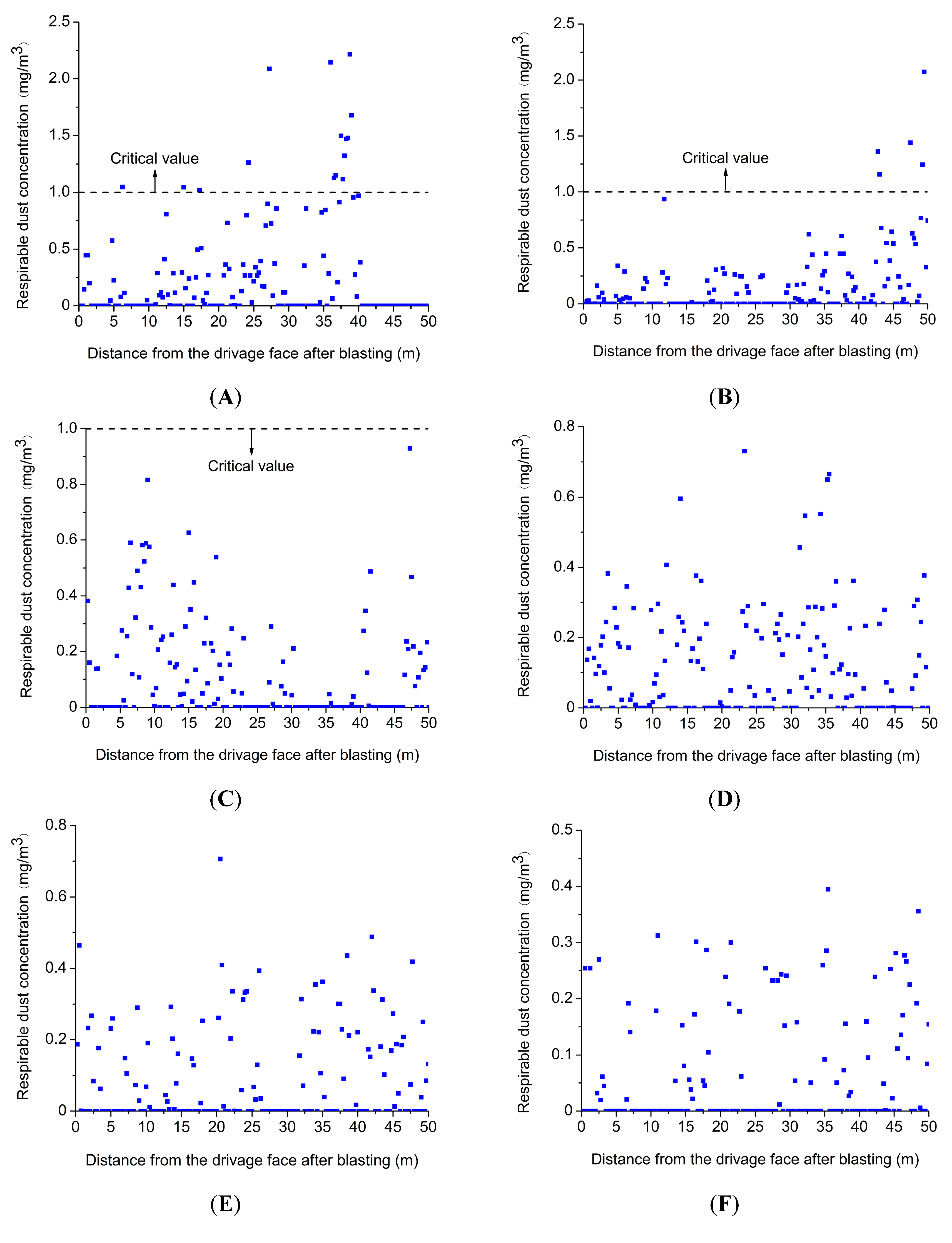
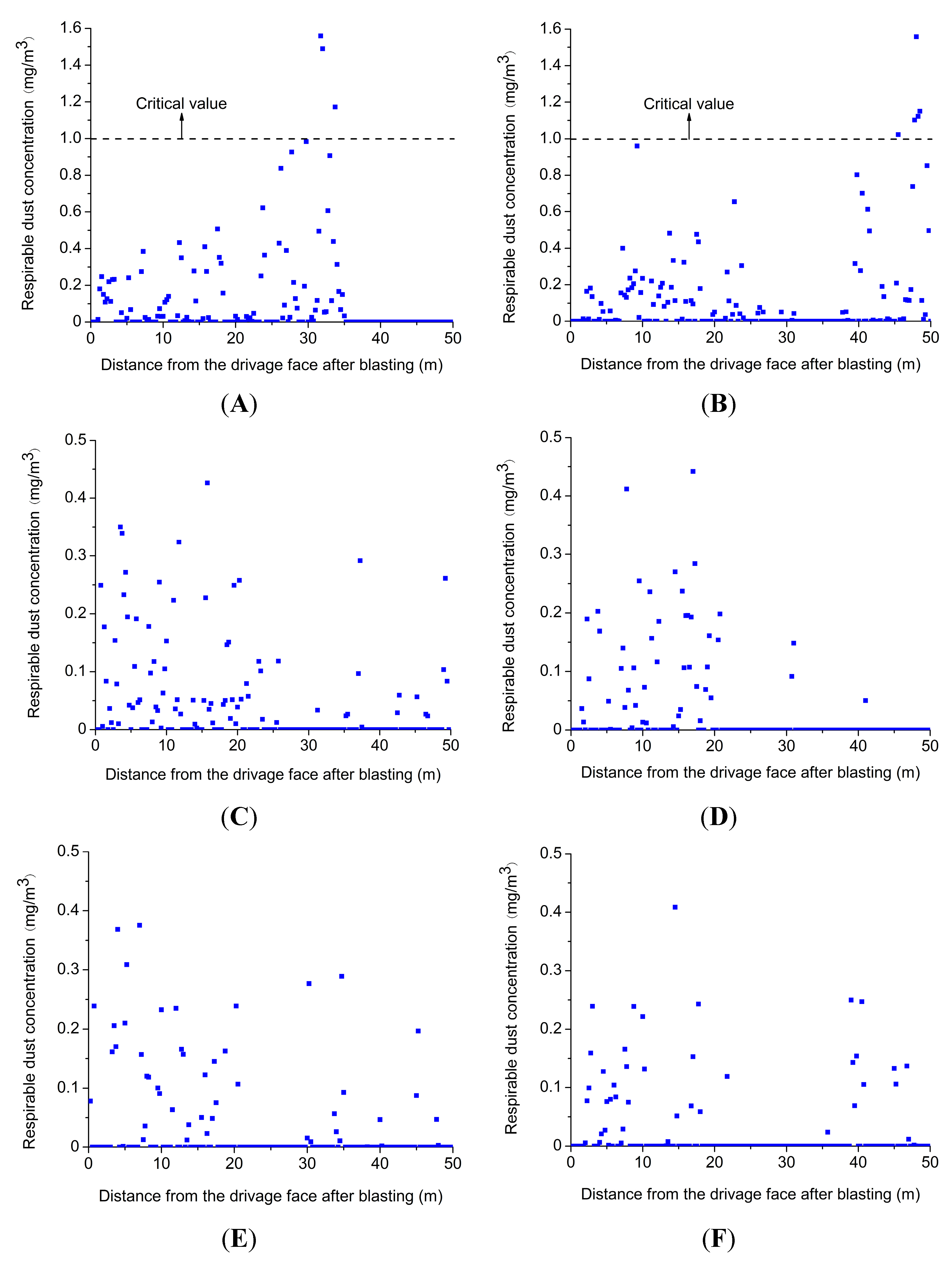
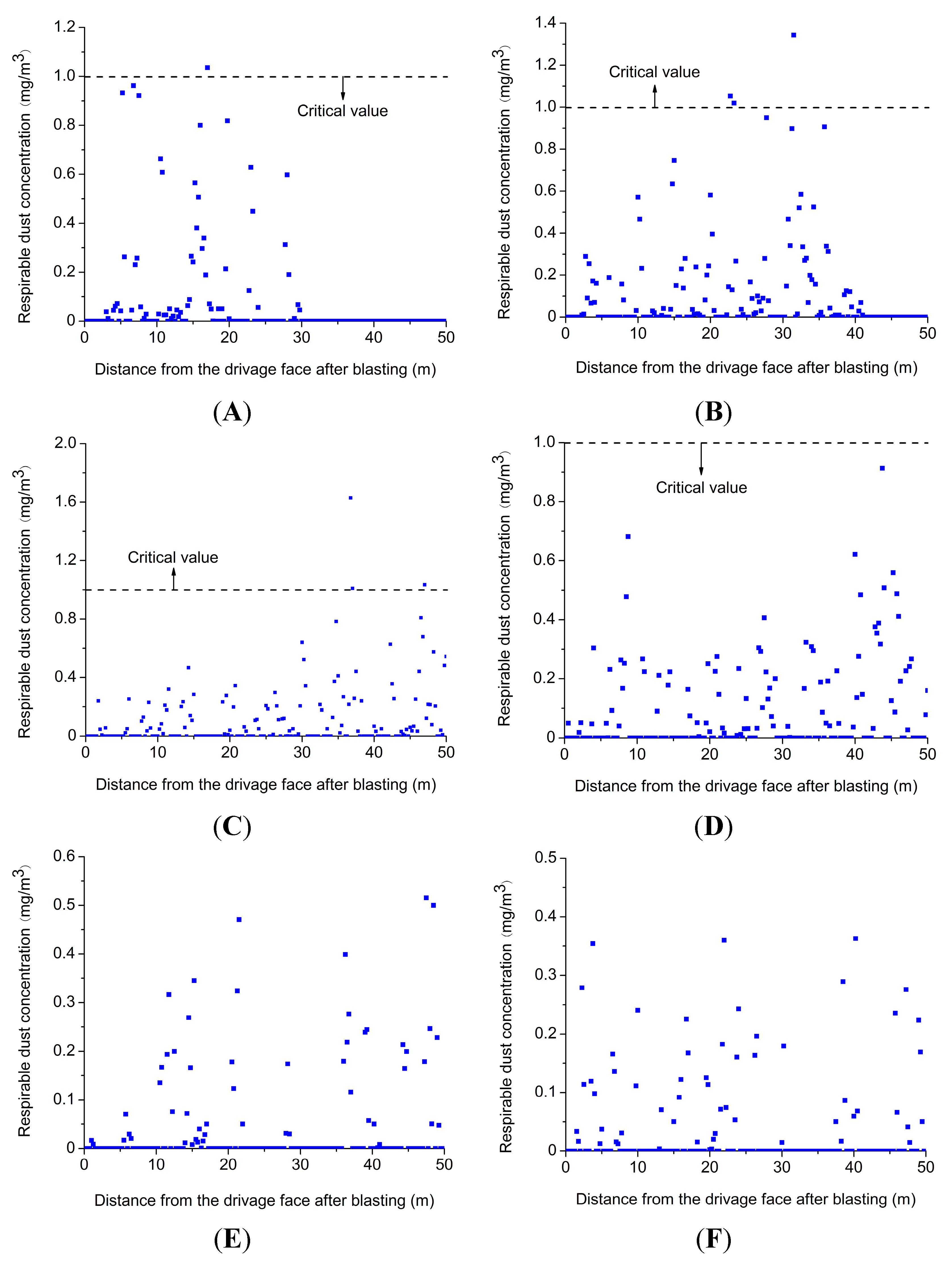
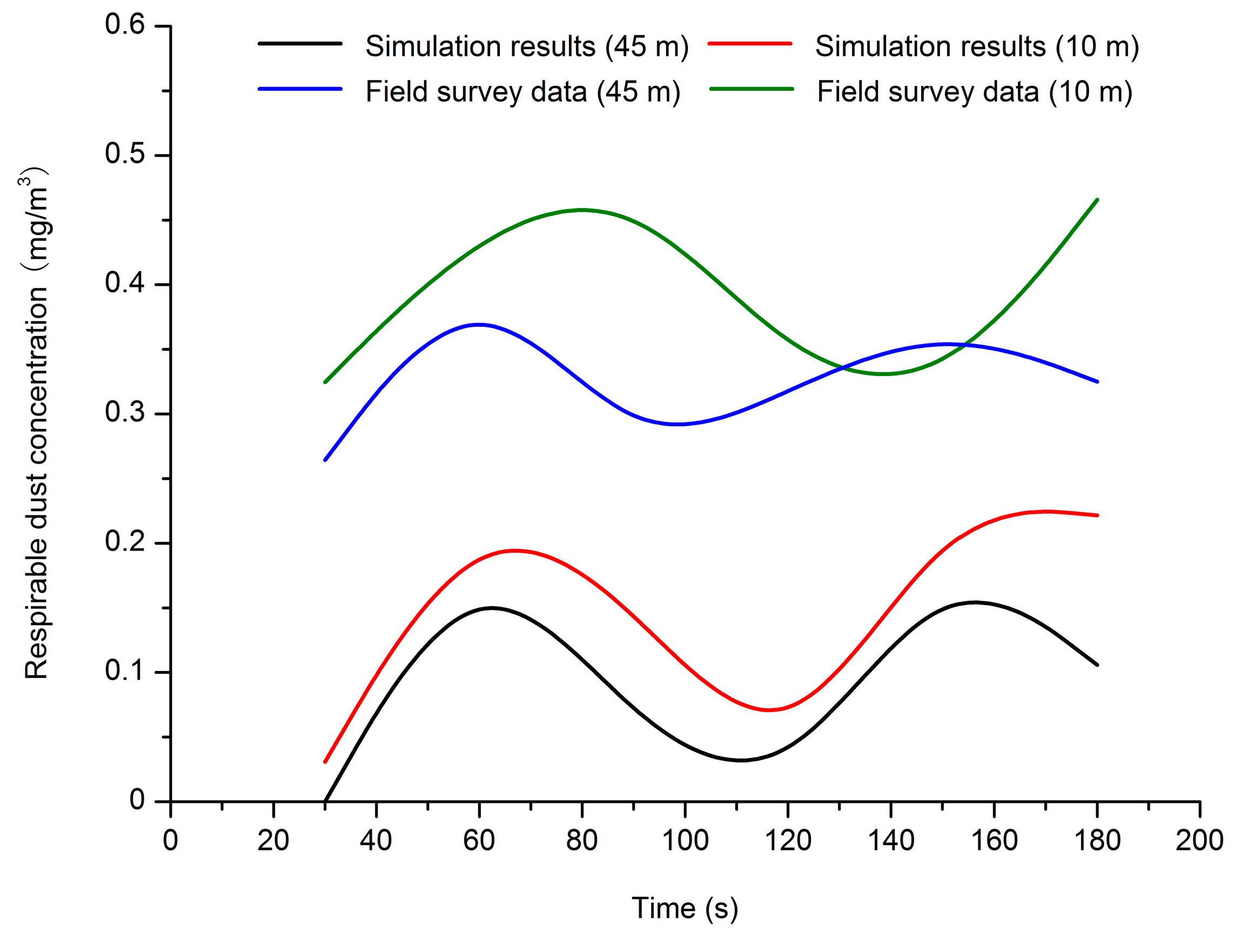
4.3. Field Verification

To verify the accuracy of the numerical simulation results, two dust concentration detection points are established on the roadway axis, 10 and 45 m away, respectively, from the driving face head-on before blasting and located in the breathing zone when constructing to about 50 m in II 030702 intake airflow roadway of Wulan mine. The sample data we take from these two detection points are used as the measured results to be compared with the simulation results of respirable dust concentration after blasting. A direct-reading dust detector [25] is used to monitor the respirable dust concentration of blasting driving face after blasting. The working principle of the β-rays method is that the respirable dust mass can be calculated through changes in β-rays’ intensity received by a β-ray detector. The respirable dust mass concentration over the sampling duration is obtained according to the sampling volume. This method can realize automatic, continuous monitoring in a measurement range of 0.2–1000 mg/m3.
Figure 8 shows the comparison of measured data of respirable dust concentration and the numerical simulation results. As shown in Figure 8, on the whole respirable dust concentration exhibits a wavy distribution over time after blasting, indicating that the gas–solid two-phase flow in the roadway exhibits an alternant thin dense phase distribution. A lot of dust enters the roadway at a high speed under the action of a shock wave after blasting and gradually moves to the roadway outlet under the action of the air flow. It can be seen in Figure 3 that there is an obvious vortex region at 25 m off the wind direction from the driving face. The velocity in the center of the vortex region is lower than the velocity close to the driving face and both sides of the roadway wall of the vortex region. The location at 25 m from the driving face is within the scope of the vortex region and the airflow velocity is smaller than 45 m, which results in a respirable dust concentration that at 10 m is higher than that at 45 m. However, by comparison, there is a slight deviation between the two values. In 130–160 s of field verification, the respirable dust concentration at 45 m is slightly higher than that at 10 m, which results from complex site conditions and instrumental error. By comparison and analysis, it can be concluded that the selection of mathematical and physical models is accurate on the whole and the results of the numerical simulation are credible. To a certain degree, the numerical results can be used to guide field measurements.
Figure 8. Contrast diagram of numerical simulation results and measured data.
Minerals 05 00517 g008

5. Conclusions

In this paper, based on the direct simulation Monte Carlo method, the gas–solid two-phase flow model of particle movement is established to study the respirable dust distribution in blasting driving face in Wulan coal mine. Meanwhile, the corresponding program development of multiphase flow is completed independently. The following conclusions are summarized:
There is an obvious vortex region where the airflow velocity is lower than that close to the wall and driving face. In general, airflow velocity distribution is high at the driving face and low at the roadway outlet. Respirable dust at high concentrations in the front of the respirable dust group, which is suspended for a long time in the air, can be eliminated from the roadway under the action of the air flow. The concentration of respirable dust decreases slowly and tends to stabilize gradually, exhibiting an alternate thin dense phase distribution in a roadway. The results of the respirable dust concentration distribution serve as the scientific basis for setting the parameters of designing a dust removal system so as to control the dust concentration within a critical value in the shortest possible time. Accordingly, respirable dust whose concentration is higher than the critical value moves to the roadway outlet gradually over time. On account of this, a dust removal system should be designed in accordance with the transfinite dust migration rule so as to remove dust efficiently. In addition, due to the fact that respirable dust concentration in the breathing zone is relatively higher than that at the top and bottom of roadway, more attention should be paid to this area and more dust removal devices should be installed here.
According to the results of the numerical simulation in this study, it is imperative to design an efficient dust control and removal system to ensure the health of miners.

Acknowledgments

Here, the authors show great gratitude to the Wulan mine for providing the field data used in this study.

Author Contributions

Guorui Feng designed research; Shengyong Hu built mathematical model; Zhuo Wang presented numerical simulation.

Conflicts of Interest

The authors declare no conflict of interest.

Nomenclature

u
velocity (m/s)
v
solid phase velocity (m/s)
Dp
particle diameter (m)
Re
Reynolds number
m
mass (kg)
V
velocity (m/s)
J
impulse exerted on particle 1
f
friction coefficient
e
coefficient of restitution
G
relative velocity (m/s)
n
normal unit vector
t
unit vector in the tangential direction
H
height (m)
r
particle radius

Greek Letters

ε
voidage
κ
turbulence Kinetic energy (m2·s−2)
μ
dynamic viscosity (N·s/m2)
μt
turbulent viscosity (N·s/m2)
ρ
gas phase density (kg/m3)
τ
turbulent stress tensor (Pa)
δ
Kronecker constant

References

  1. Zheng, Y.P.; Feng, C.G.; Jing, G.X.; Qian, X.M.; Li, X.J.; Liu, Z.Y.; Huang, P. A statistical analysis of coal mine accidents caused by coal dust explosions in China. J. Loss Prev. Process Ind. 2009, 22, 528–532. [Google Scholar] [CrossRef]
  2. Jimeno, E.L.; Jimino, C.L.; Carcedo, A. Drilling and Blasting of Rocks; CRC Press: Boca Raton, FL, USA, 1995. [Google Scholar]
  3. Langefors, U.; Kihlström, B. The Modern Technique of Rock Blasting; Wiley: Hoboken, NJ, USA, 1978. [Google Scholar]
  4. Wang, H.T.; Wang, D.M.; Lu, X.X.; Gao, Q.C.; Ren, W.X.; Zhang, Y.K. Experimental investigations on the performance of a new design of foaming agent adding device used for dust control in underground coal mines. J. Loss Prev. Process Ind. 2012, 25, 1075–1084. [Google Scholar] [CrossRef]
  5. Erol, I.; Aydin, H.; Didari, V.; Ural, S. Pneumoconiosis and quartz content of respirable dusts in the coal mines in Zonguldak, Turkey. Int. J. Coal Geol. 2013, 116–117, 26–35. [Google Scholar] [CrossRef]
  6. Xi, Z.L.; Jiang, M.M.; Yang, J.J.; Tu, X. Experimental study on advantages of foam-sol in coal dust control. Process Saf. Environ. Prot. 2014, 92, 637–644. [Google Scholar]
  7. Tien, J.C. Dust control practices in Chinese coal mines, with remarks on black lung. Eng. Min. J. 2011, 63, 24–29. [Google Scholar]
  8. Amato, F.; Querol, X.; Johansson, C.; Nagl, C.; Alastuey, A. A review on the effectiveness of streets weeping, washing and dust suppressants as urban PM control methods. Sci. Total. Environ. 2010, 408, 3070–3084. [Google Scholar] [CrossRef] [PubMed]
  9. Smitham, J.B.; Nicol, S.K. Physico-chemical principles controlling the emission of coal dust stockpiles. Powder Technol. 1991, 64, 259–270. [Google Scholar] [CrossRef]
  10. Medeiros, M.A.; Leite, C.M.M.; Lago, R.M. Use of glycerol by-product of biodiesel to produce an efficient dust suppressant. Chem. Eng. J. 2012, 180, 364–369. [Google Scholar] [CrossRef]
  11. Zhang, X.K.; Zhou, G. Technology of high-efficiency comprehensive dust removal in whole rock fully mechanized driving face. Chin. J. Coal Sci. Technol. 2013, 41, 81–83. [Google Scholar]
  12. Li, Y.C.; Liu, J. Numerical simulation of dust control using air curtain based on gas-solid two-phase flow. Chin. J. Liaoning Tech. Univ. 2012, 31, 765–769. [Google Scholar]
  13. Wang, Y.C.; Luo, G.; Geng, F.; Li, Y.B.; Li, Y.L. Numerical study on dust movement and dust distribution for hybrid ventilation system in a laneway of coal mine. J. Loss Prev. Process Ind. 2015, 36, 146–157. [Google Scholar] [CrossRef]
  14. Wang, H.; Jiang, Z.A.; Du, C.F.; He, Z.L.; Hu, G.Y. Field study and numerical research on dust concentration distribution in the excavation tunnel. Chin. J. Liaoning Tech. Univ. 2011, 33, 345–348. [Google Scholar]
  15. Wang, H.; Jiang, Z.A.; Huang, L.T.; Liao, X.X.; Wand, J.R. Experimental research on pressing air-absorption air volumeratio in FPNA ventilation for excavation roadways. Chin. J. Liaoning Tech. Univ. 2011, 30, 168–171. [Google Scholar]
  16. Toraño, J.; Torno, S.; Menéndez, M.; Gent, M. Auxiliary ventilation in mining roadways driven with roadheaders: Validated CFD modelling of dust behavior. Tunn. Undergr. Space Technol. 2011, 26, 201–210. [Google Scholar] [CrossRef]
  17. Kurnia, J.C.; Sasmito, A.P.; Mujumdar, A.S. Dust dispersion and management in underground mining faces. Int. J. Min. Sci. Technol. 2014, 24, 39–44. [Google Scholar] [CrossRef]
  18. Wang, Z.W.; Ren, T. Investigation of airflow and respirable dust flow behaviour above an underground bin. Powder Technol. 2013, 250, 103–114. [Google Scholar] [CrossRef]
  19. Zhang, S.Z.; Cheng, W.M.; Zhou, G.; Yang, P.; Qi, Y.D. Study on dust density measurement accuracy of fully mechanized caving face. In Proceeding of the International Symposium on Safety Science and Technology, Beijing, China, 24–27 September 2008; pp. 1488–1492.
  20. Sa, Z.Y.; Li, F.; Qin, B.; Pan, X.H. Numerical simulation study of dust concentration distribution regularity in cavern stope. Saf. Sci. 2012, 50, 857–860. [Google Scholar] [CrossRef]
  21. Levy, A. Two-fluid approach for plug flow simulations in horizontal pneumatic conveying. Powder Technol. 2000, 112, 263–272. [Google Scholar] [CrossRef]
  22. Tsuji, Y.; Tanaka, T.; Yonemura, S. Cluster patters in circulating fluidized beds predicted by numerical simulation (discrete particle model versus two-fluid model). Powder Technol. 1998, 95, 254–264. [Google Scholar] [CrossRef]
  23. Hoomans, B.P.B.; Kuipers, J.A.M.; van Swaaij, W.P.M. Granular dynamics simulation of segregation phenomena in bubbling gas-fluidized beds. Powder Technol. 2000, 109, 41–48. [Google Scholar] [CrossRef]
  24. China State Administration of Work Safety. Specification of Coal and Gas Outburst Prevention; China Coal Industry Press: Beijing, China, 2011. [Google Scholar]
  25. Bian, M.L. PM2.5 dust concentration distribution law of open pit coal mine during perforation and transportion. Chin. Saf. Coal Mines 2015, 46, 50–53. [Google Scholar]

