Gate Antiphase of Potassium Channel

Projects and Physics Section, Sapir Academic College, D.N. Hof Ashkelon 79165, Israel
Symmetry 2017, 9(8), 150; https://doi.org/10.3390/sym9080150
Submission received: 19 June 2017
/
Revised: 5 August 2017
/
Accepted: 6 August 2017
/
Published: 8 August 2017
(This article belongs to the Special Issue Symmetry in Structural Biology)
Abstract
:Potassium channels are integral membrane proteins that selectively transport K+ ions across cell membranes. They function through a pair of gates, which work in tandem to allow the passage of the ions through the channel pore in a coupled system, to which I refer to here as the “gate linker”. The functional mutation effects, as described in the literature, suggest that the gate linker functions analogously to a triad of coiled springs arranged in series. Accordingly, I constructed a physical model of harmonic oscillators and analyzed it mechanically and mathematically. The operation of this model indeed corresponds to the phenomena observed in the mutations study. The harmonic oscillator model shows that the strength of the gate linker is crucial for gate coupling and may account for the velocity, direction, and efficiency of ion transfer through the channel. Such a physical perspective of the gating process suggests new lines of investigation regarding the coupling mode of potassium channels and may help to explain the importance of the gate linker to channel function.
1. Introduction
Potassium channels are homotetramers that, by selectively transferring potassium ions across the cell membrane, hyperpolarize the cell to form the energetic basis for neuronal and muscular activity [1]. The ionic currents through the pore are regulated by two coupled gates: an upper inactivation gate and a lower activation gate (Figure 1) [1]. The gating process of the potassium channel underlies the production of electrical impulses known as action potentials—transient fluctuations in the membrane voltage—that spread across the surface of a cell, allowing neurons, for example, to transmit electric signals very rapidly over their length.
The current study provides a model for the coupling between the activation and inactivation gates, focusing on voltage-dependent (Kv) and leak (K2P) potassium channels. Notably, the activation–inactivation gate coupling is functionally different between the two types of channel: whereas coupling is bidirectional in Kv channels—namely, the activation gate induces the closure of the inactivation gate [2,3] and vice versa [4,5], it is unidirectional in K2P channels, in which the activation gate induces the closure of the inactivation gate [6].
The current study aimed to examine the importance of the gate linker for the gate-coupling mechanism and to provide a novel view on the physical properties of the channel, thereby explaining what causes the channel to be in an open or a closed conformation. To this end, a system of springs was constructed analogously to voltage-dependent and leak potassium channels. This system includes three springs aligned in series, such that each spring represents a different part of the channel (Figure 1). The sensors that stimulate and, thereby, activate the activation and inactivation gates of the channel are represented by two external springs (defined here as the ‘sensing springs’—k), which mimic the extracellular and intracellular regions of the channels; in real-world channels, these sensors are sensitive to voltage (in voltage-dependent channels) or to mechanical stimuli. Once these springs move, they elicit movement in the channel and immediately activate both gates. This activation results in channel movement—either opening or closing the channel. The third spring (defined here as the ‘coupling spring’—) connects the two gates and thus represents the gate linker. In real-world channels, this spring represents the amino acids that connect the activation and inactivation gates, and it is affected by the external surroundings (e.g., by the two external springs). Mechanical changes in the coupling spring are analogous to mutations in the gate linker region of the real-world potassium channel.
2. Materials and Methods
Data Analysis
I used MATLAB 8.0 and Statistics Toolbox 8.1 software (Apple, Natick, MA, USA) to illustrate the simulation of the potassium channel.
3. Results and Discussion
It has been previously demonstrated [7,8,9,10] that in K+ channels, both sides of the channel affect the gate-linker—results confirmed and amplified in the present study. This gate-linker has a major role in the coupling between the two gates.
It has been shown that mutations in the amino acids that appear near the gate-linker region can significantly affect the gating process [11,12,13]. This fact prompts the question: is the gate linker an independent mechanism? In other words, is the region of the protein that constitutes the gate linker solely responsible for its functioning or do other amino acids outside this region affect it too? To gain further insights into the mechanism underlying the coupling between the gates, I modeled channel gating as a mechanically coupled springs system and tested its behavior when the coupling spring, which models the gate linker, is either weak or absent. In this model, stretching the inactivation gate to the ‘open’ state at the rate of X1 shrinks the activation gate at the rate of X2 and the coupling spring by the difference X2 − X1. Hence, the movement equilibrium of the two gates, which describes how the movement of one gate is affected by the movement of the other, can be expressed as:
First, I subtract or add Equations (1) and (2) to model the absence of coupling. After dividing the mass of the gate, I get:
where:
Combining Equations (3) and (4) yields:
These equations describe the new coordinates for the sum and difference that are not conjugated, and, therefore, act harmoniously as:
where A, B, α, and β are determined by the initial conditions.
The velocity at which the channel opens or closes (reflected, in real-world potassium channels, in the velocity of the ionic current through the pore) is one of the determinants of the direction of the gates (i.e., whether each gate will open or close). The physical model suggests that the strength of the gate linker (the coupling spring) critically affects the coupling between the gates and may account for the direction of the gate and the velocity and efficiency of ion transfer through the pore. Thus, movement of both gates (springs) in the same direction and velocity weakens the coupling spring. Each gate moves with an identical angular frequency rate of:
In the scenario described in Equation (13), the middle spring, k1, is weak but the velocity of the ionic current is too low to adequately control gate opening or closing. Considering the importance of the gate linker region (modeled as the coupling spring) for channel gating, this scenario should be impossible. Conversely, when both gates move in opposite directions (i.e., one opens while the other closes), and under the assumption that the velocity of gate opening is equal in size and opposite in direction to gate closing, then the coupling spring is stretched or contracted in such a way that a spring constant exerts force on both gates. Such a spring should thus move with the higher angular frequency of:
Mutations in the gate linker region of real-world potassium channels are thus analogous to weakening the coupling spring in the model as a result of activation reduction, such that:
The explanation of this scenario requires the system to be engaged non-symmetrically. At t = 0, the upper inactivation gate (Figure 1) moves to the right at a rate of A1. In this case, I return to the original variables:
while the initial conditions are:
By substituting these values into Equations (16) and (17), I get: α = β = 0 and A = B. Using these values in Equations (16) and (17) gives:
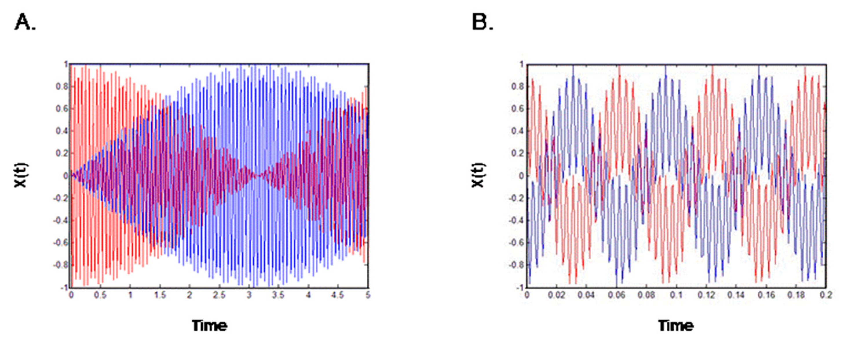
Figure 2A represents Equation (19) and indicates that energy was transferred from one gate to the other and that the amplitude of movement of one gate was increased, while that of the other was decreased. The gates are thus poorly coordinated and, in the real-world analog, the ions would not pass through the pore. The opposite scenario, in which the two gates are coordinated, is represented by the equation:
In this scenario, the two gates operate in opposite directions due to the very strong spring.
In the specific cases in which the coupling spring is much weaker than spring k, I get:
where
and
where
These equations are the product of two harmonic functions—one with a high frequency, ω0, and the other with a low frequency, ∆ω—both serving to shape the amplitude of the movement. Overall, the model indicates that the activation and inactivation gates move in anti-phase; when the movement of the first gate decreases, the movement of the second gate increases, and when the first gate stops moving, all the energy is transferred to the second gate via the coupling spring. Thus, the direction of gate movement and the coupling between the gates appear to be completely interdependent, such that a malfunction in either one of the gates is immediately manifested as channel dysfunction. These results further show that the open gate direction has a high dependency on the coupling. Thus, malfunction in one gate of the potassium channel results from the lack of coupling.
4. Conclusions
The gate linker physically connects the activation and inactivation gates of potassium channels and plays a fundamental role in the flow of ionic currents through the pore. Mutations in this region, as presented in literature [9,10,11,12,13], greatly affect the gating process and a mechanistic model indicates that weakening the coupling spring that simulates the gate linker region decouples the gates and dramatically decreases the overall function of the channel. Simulating the direction of gate movement in the mechanistic model revealed that the coupling spring stretches or contracts when the gates move in opposite directions, and malfunctions when the gates move in the same direction, leading to overall system malfunction. Thus, the coupling of the two gates appears to play a dual role in potassium channels, namely, it enables channel gating and makes the gating directions essential to whether the potassium ions can enter the channel. Thus, both the direction of movement of the gates and the coupling between them appears to have a substantial effect on channel function.
Conflicts of Interest
The authors declare no conflicts of interest.
References
- MacKinnon, R. Potassium channels. FEBS Lett. 2003, 555, 62–65. [Google Scholar] [CrossRef]
- Baukrowitz, T.; Yellen, G. Modulation of K+ current by frequency and external [K+]: A tale of two inactivation mechanisms. Neuron 1995, 15, 951–960. [Google Scholar] [CrossRef]
- Baukrowitz, T.; Yellen, G. Two functionally distinct subsites for the binding of internal blockers to the pore of voltage-activated K+ channels. Proc. Natl. Acad. Sci. 1996, 93, 13357–13361. [Google Scholar] [CrossRef] [PubMed]
- Panyi, G.; Deutsch, C. Cross talk between activation and slow inactivation gates of Shaker potassium channels. J. Gen. Physiol. 2006, 128, 547–559. [Google Scholar] [CrossRef] [PubMed]
- Panyi, G.; Deutsch, C. Probing the cavity of the slow inactivated conformation of shaker potassium channels. J. Gen. Physiol. 2007, 129, 403–418. [Google Scholar]
- Ben-Abu, Y.; Zhou, Y.; Zilberberg, N.; Yifrach, O. Inverse coupling in leak and voltage-activated K+ channel gates underlies distinct roles in electrical signaling. Nat. Struct. Mol. Biol. 2009, 16, 71–79. [Google Scholar] [CrossRef] [PubMed]
- Li-Smerin, Y.; Swartz, K.J. Helical structure of the COOH terminus of S3 and its contribution to the gating modifier toxin receptor in voltage-gated ion channels. J. Gen. Physiol. 2001, 117, 205–218. [Google Scholar] [CrossRef] [PubMed]
- Hackos, D.H.; Chang, T.H.; Swartz, K.J. Scanning the intracellular S6 activation gate in the shaker K+ channel. J. Gen. Physiol. 2002, 119, 521–532. [Google Scholar] [CrossRef] [PubMed]
- Li-Smerin, Y.; Swartz, K.J. Localization and molecular determinants of the Hanatoxin receptors on the voltage-sensing domains of a K(+) channel. J. Gen. Physiol. 2000, 115, 673–684. [Google Scholar] [CrossRef] [PubMed]
- Li-Smerin, Y.; Hackos, D.H.; Swartz, K.J. Alpha-helical structural elements within the voltage-sensing domains of a K(+) channel. J. Gen. Physiol. 2000, 115, 33–50. [Google Scholar] [CrossRef] [PubMed]
- Hoshi, T.; Zagotta, W.N.; Aldrich, R.W. Biophysical and molecular mechanisms of shaker potassium channel inactivation. Science 1990, 250, 533–538. [Google Scholar] [CrossRef]
- Yifrach, O.; MacKinnon, R. Energetics of pore opening in a voltage-gated K(+) channel. Cell 2002, 111, 231–239. [Google Scholar] [CrossRef]
- Sadovsky, E.; Yifrach, O. Principles underlying energetic coupling along an allosteric communication trajectory of a voltage-activated K+ channel. Proc. Natl. Acad. Sci. USA 2007, 104, 19813–19818. [Google Scholar] [CrossRef] [PubMed]
Figure 1.
The structure of a potassium channel (left) and its spring-system analogue (right). The sensing springs are analogous to the upper and lower gates of the channel, and the coupling spring is analogous to the gate linker, which connects the two gates.
Figure 1.
The structure of a potassium channel (left) and its spring-system analogue (right). The sensing springs are analogous to the upper and lower gates of the channel, and the coupling spring is analogous to the gate linker, which connects the two gates.
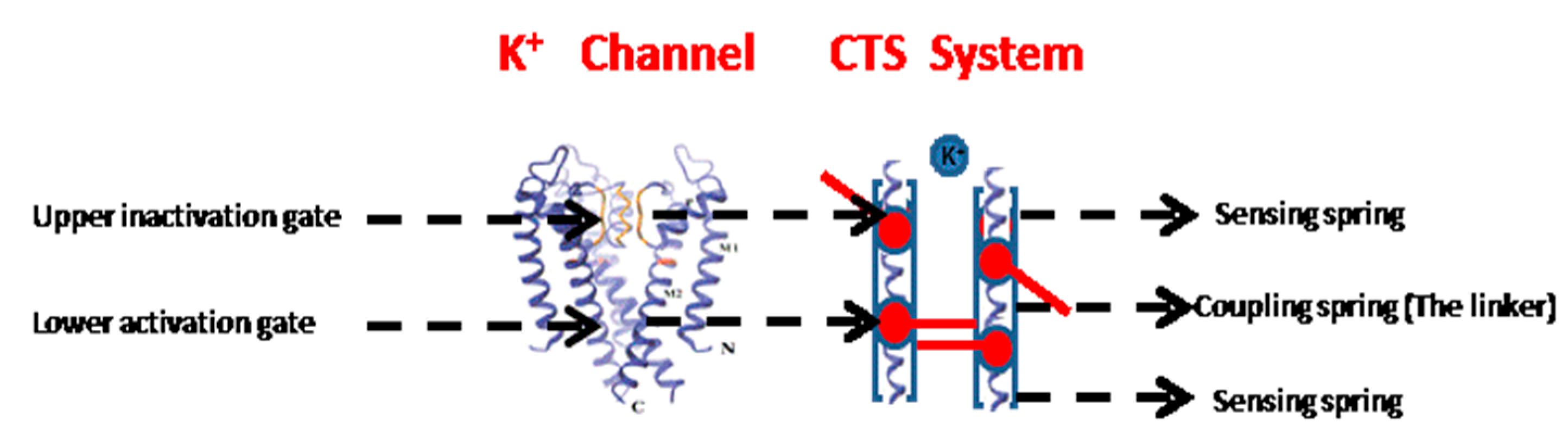
Figure 2.
Schematic description of potassium channel gates harmonic behavior. (A) A weak coupling spring; when one gate opens, the other gate closes; (B) A regular coupling spring; the direction of both gates is coordinated.
Figure 2.
Schematic description of potassium channel gates harmonic behavior. (A) A weak coupling spring; when one gate opens, the other gate closes; (B) A regular coupling spring; the direction of both gates is coordinated.
© 2017 by the author. Licensee MDPI, Basel, Switzerland. This article is an open access article distributed under the terms and conditions of the Creative Commons Attribution (CC BY) license (http://creativecommons.org/licenses/by/4.0/).
Share and Cite
MDPI and ACS Style
Ben-Abu, Y. Gate Antiphase of Potassium Channel. Symmetry 2017, 9, 150. https://doi.org/10.3390/sym9080150
AMA Style
Ben-Abu Y. Gate Antiphase of Potassium Channel. Symmetry. 2017; 9(8):150. https://doi.org/10.3390/sym9080150
Chicago/Turabian StyleBen-Abu, Yuval. 2017. "Gate Antiphase of Potassium Channel" Symmetry 9, no. 8: 150. https://doi.org/10.3390/sym9080150
Note that from the first issue of 2016, this journal uses article numbers instead of page numbers. See further details here.