Rapid Evaluation and Analysis of the Deformation of Filled Cylindrical Casing with Deforming Charge Width Based on Self-Compiled MATLAB Program


College of Liberal Arts and Sciences, National University of Defense Technology, Changsha 410073, China
*
Author to whom correspondence should be addressed.
Symmetry 2018, 10(8), 310; https://doi.org/10.3390/sym10080310
Submission received: 26 June 2018
/
Revised: 17 July 2018
/
Accepted: 25 July 2018
/
Published: 1 August 2018
Abstract
:The casing of deformable warheads warps under the action of deforming charges. The deformation profiles may be concave-, convex-, or D-shaped, but they are all symmetrical. The D-shape is considered the optimal deformation profile. The width of the deformed surface affects the number of fragments in the target area. In order to evaluate the deformable surface width of the cylindrical casing, a criterion α was established and its optimum range was determined as 20 to 30%. Based on our previous theoretical analysis, a MATLAB program that can rapidly evaluate the projectile deformation surface was compiled, which was verified using LS-DYNA and experiments. The laws influencing the deforming charge width on the deformed surface of the filled cylindrical casing were also studied using the MATLAB rapid evaluation program. As the deforming charge width increased, the deformation profile of the casing gradually transferred from “inner-concave” to the “outer-convex”. In addition, a formula that can better reflect the relationship between the deforming charge width φ and the criterion value α was fitted and verified. The conclusions obtained in this paper provide rapid guidance for the structural design of deformable warheads.
1. Introduction
The dynamic responses of cylindrical casing structures under lateral impact loading often affect the national defense industry. Taking the deformable warhead as an example, the casing cross-section of a deformable warhead changes from circular to non-circular under the explosive loading of lateral deforming charge. In 1971, Kempton [1], who worked in the Navy Air Weapons Research Center, first proposed the deformable warhead prototype. Konig and Mostert [2] designed and improved the structure of the deformable warhead on the basis of previous studies, and some conventional knowledge was obtained. Lloyd [3] (pp. 49–59) reported the mechanism of deformable warheads and the obtained conclusions were enlightening. In the 1990s, Fairlie et al. [4] conducted a series of numerical simulations on the deformation mechanism of deformable warheads and the scattering process of fragments using AUTODYN-3D. Compared with the conventional fragment warhead, the deformable warhead can increase the fragment density gain and fragment velocity gain on the target, thereby increasing the damage probability of the target.
In order to facilitate the theoretical study, the deformable warhead deformation process under the action of deforming charge can be simplified into filled cylindrical casings under lateral loading. The type of lateral loading and the difference in the filling medium directly affect the dynamic response of the cylindrical casing. Tennyson [5] analyzed the buckling mechanism of the cylindrical casing structure in the fields of aerospace, missiles, and other weapons systems through experiments and simulations. Lindberg et al. [6] studied the transition relationships between the asymmetric load and symmetric load for the thick- and thin-walled casing structure. Gefken et al. [7] performed some buckling tests on the short cylindrical casing clamped at both ends under cosine impact loading, and the conclusion was verified by Kirkpatrick [8] using DYNA-3D. Yakupov [9,10] studied the deformation of free cylindrical casings under the action of plane and spherical waves, and the typical plastic hinge theory was applied to analyze the deformation process. Based on the theory of plastic hinges, Wierzbicki et al. [11] established the theoretical analysis model of finite length, infinite length, and stiffened cylindrical shell under the action of lateral impact loading. Hoo Fatt et al. [12] discussed the deformation and failure of free cylindrical casing under local impact loading and different load distribution types. Hu et al. [13] studied the influences of elastic modulus, casing radius, and thickness on the transient response of cylindrical casing. Yao et al. [14] proposed a new impact factor to describe underwater explosive loading. Li and Rong [15] studied the dynamic response of cylindrical casing structure subjected to underwater explosion. Hung et al. [16] investigated the dynamic response of three kinds of cylindrical casing structures subjected to underwater explosion under different stand-off distances.
In addition, many scholars have reported the response of cylindrical casing with different types of filling medium. Ma et al. [17] studied the lateral impact of spherical projectiles on the metal cylindrical casing filled with water or sand. Neilson et al. [18] analyzed the relationships between the critical penetration speed and internal pressure, based on impact tests on filled steel tubes. Gefken et al. [7] studied the dynamic response of free cylindrical shells under lateral impulsive loading, and the effect of internal pressure on the deformation of cylindrical shells was obtained. Li et al. [19] established the theoretical analysis model of metal cylindrical casing filled with liquid under lateral plane impact loading. Jama et al. [20] conducted experimental and analytical studies on the deformation of square hollow steel sections subjected to lateral blast loading. Li et al. [21] investigated two kinds of the cylindrical shell models with the same geometry characteristics: unfilled and filled with sand. Based on the plane strain hypothesis and plastic hinge theory, Ding [22,23,24,25] and Li [26] studied the deformation mechanism of filled cylindrical casings under lateral explosive loading. The dispersion rule of fragments and energy output were also studied.
For deformable warheads, the deformation profile of the casing mainly involves the deformation width and deformation shape. The deformation width and shape affect the number of effective fragments and the fragment density in the target area, respectively. In this paper, we only study the deformable surface width of the projectile. Therefore, the deformation of the cylindrical casing filled medium under lateral explosive loading is simplified. By drawing on the analysis methods used previously, we aimed to establish a criterion to evaluate the deformable surface width, and compile a MATLAB program to achieve rapid evaluation of deformable surfaces. Moreover, we wanted to establish a formula that can better reflect the relationship between the deforming charge width and criterion value, to provide rapid guidance for engineering applications.
2. Criterion α for Measuring the Deformable Surface Width
2.1. Establishment of Criterion α
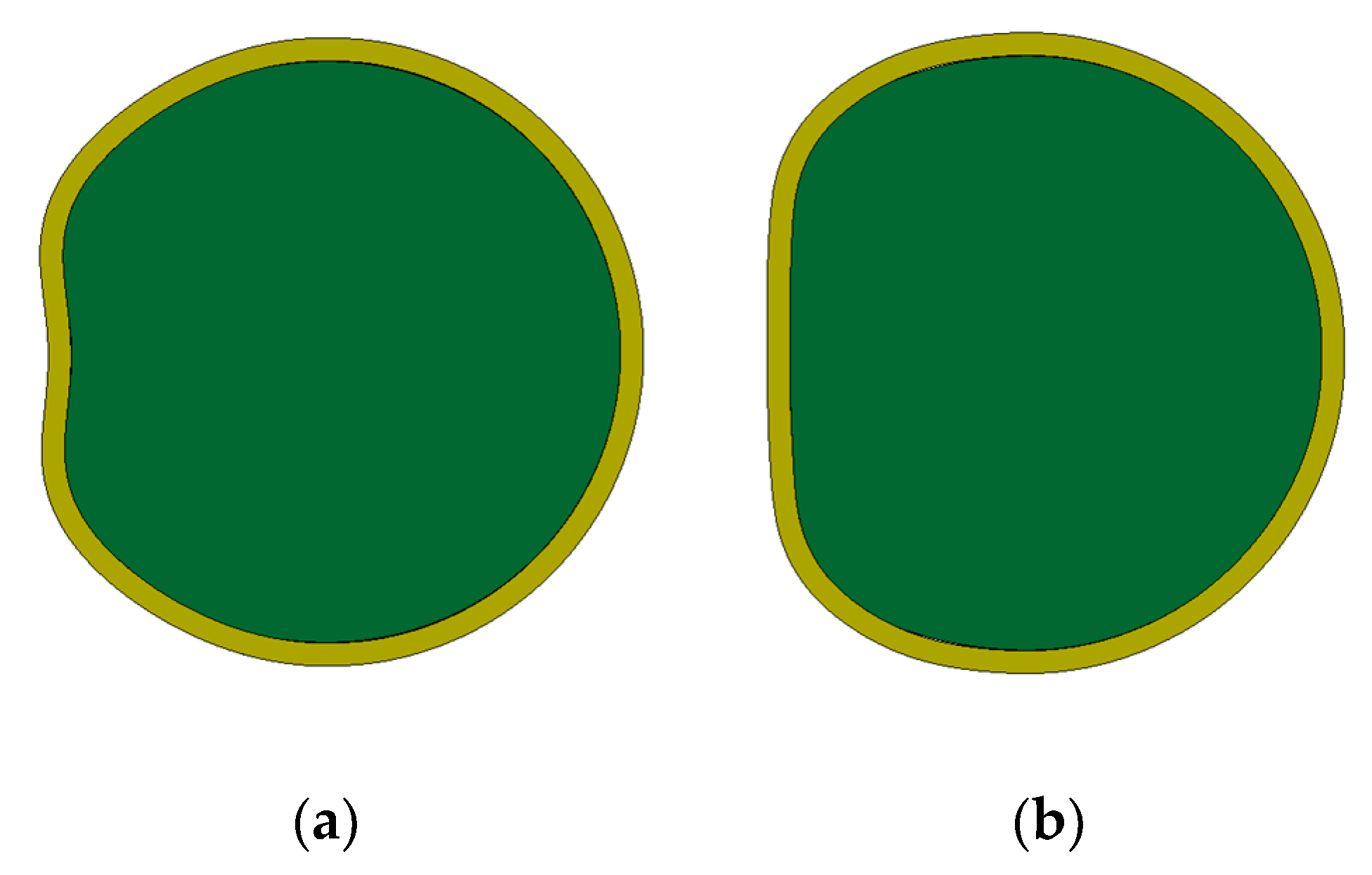
After the lateral explosive loading of a deforming charge, the casing of a deformable warhead is crushed under the action of the detonation products and detonation waves, and the projectile deformed surface is shown in Figure 1. According to the literature [3] (pp. 192–209), when the casing surface is similar to a D-shape, the fragments have the highest damage efficiency on the target. The above assumption enabled the theoretical analysis of deformable warheads, and the D-shaped profile is defined as the ideal casing profile of a deformable warhead. In combat requirements, ensuring the number of fragments is necessary, while also ensuring that the fragment velocity is as high as possible. Therefore, studying the optimum surface width of the D-shaped structure is essential.
The profile of a deformable warhead becomes non-circular under the action of a deforming charge, and the profile of a deformed casing is shown in Figure 2a. As mentioned above, the D-shaped profile is defined as the ideal profile of a deformable warhead. To simplify further analysis below, the deformed profile of the projectile is D-shaped, as shown in Figure 2b.
In order to facilitate the following geometric analysis, the following definitions are required: the initial radius of cylindrical casing is O1D = R0, the initial center is O1, the casing radius after deformation is O2A = R1, the corresponding center is O2, the chord length of the plane part is AE = 2h, the center angle of the chord length is AO2E = 2δ, and the central angle corresponding to the initial deforming charge is BO1D = 2θ, as shown in Figure 2b. In addition, the y-axis is parallel to the loading direction, and the x-axis is perpendicular to the loading direction. Criterion α is defined as the proportion of the deformed portion to the entire cylindrical casing. Thus, the expression of criterion α is as follows:
In the analysis of geometric relations, it is assumed that the length of the entire cylindrical casing is not stretched in the circumferential direction. The circumference of the initial cylindrical casing is expressed as:
The circumference of the deformed cylindrical casing is expressed as:
Based on the prerequisites above, the following relationships exist:
Thus, the expression of criterion α can be rewritten as:
According to the above formulas, the parameter R0 is known, and if any of the parameters δ or R1 is known, another parameter can be calculated. Then, α can be calculated from the obtained parameter. Taking the radius of cylindrical casing R0 = 50.5 mm as an example, combined with the above geometric analysis, the proportions of the straight segment and arc segment under five groups of different conditions (D-30°, D-60°, D-90°, D-120°, and D-150°) are shown in Table 1 and Figure 3.
2.2. Optimum Range of Criterion α
To study the dispersion rule of fragments, we analyzed four groups of different D-shaped warhead structures (center angles 2δ of the D-shaped structures were 60°, 90°, 120°, and 150°) under center point initiation. In the following, D-60°, D-90°, D-120°, and D-150° are used to represent the four structures. Taking D-90° and D-120° as examples, the cross-sectional views of the D-shaped structures are shown in Figure 4. The above four kinds of conditions were simulated by using the finite element software LS-DYNA, and the energy density distribution, and the total energy distribution of fragments in the target direction were obtained, as shown in Figure 5.
Since the entire structure is symmetrical, we only needed to study half of it. In the azimuth angle of 0–30° on the target plate, the total energy of the fragments per 2° was counted, as shown in Figure 5a. Then, the energy density was obtained by dividing the total energy of the fragments by the interval width 2°, as shown in Figure 5b. In order to more intuitively compare the energy gain of fragments, the circumferential uniform cylindrical structure was also simulated, and the results were used as the base data. As can be seen from Figure 5a, the curvature of the curves represents the energy-focusing effect of the corresponding structure, and the total energy of the fragments corresponding to the four D-shaped structures is significantly higher than that of the circumferential uniform cylindrical structure. In the four structures, the energy gain of fragments corresponding to the D-60° structure was relatively low. Although the planar portion of the D-150° structure was relatively wide, the total energy and energy focusing ability of fragments could not reach the optimum at a target distance of 3.5 m. However, the total energy and energy focusing ability of the D-90° and D-120° fragment structures were close to each other, and they were the highest among the four structures. In addition, we found that the azimuth ranges of the D-90° and D-120° structures on the target containing 90% semi-prefabricated fragments were approximately −10.8°~10.8° and −11.9°~11.9°, respectively. Compared with the circumferential uniform cylindrical structure, the total energy gain of the D-90° fragments was 241.7% in the same azimuth range, and that of the D-120° was 232.6%.
As seen in Figure 5b, the energy density of the fragments of the D-60° structure was relatively insignificant because the D-60° structure was relatively close to the circumferential uniform cylindrical structure. For the other three D-shaped structures, the structures with a smaller planar width had a higher energy density near the azimuth angle of 0°; the energy density of the fragments was basically flat and then rapidly decreased near the azimuth angle of 6°. The energy density of the fragments had a platform segment in the 20–30° azimuth range, and the platform with a wider plane had a higher platform height.
In summary, for the D-shaped structure, if the center angle is between 90 and 120°, the fragment energy density and the total energy gain of the fragments were more obvious on the target direction. According to the above definition of α, the values of α corresponding to D-90° and D-120° were 22.8 and 29.2%, respectively. In other words, if the value of α falls 22.8–29.2%, the deformable warhead structure can extoll more damage. Considering the simulation error, the range is extended to 20–30%, which is set as the default range in the following section.
3. Self-Compiled MATLAB Rapid Evaluation Program
In engineering applications and considering experiment costs, finite element software, such as LS-DYNA, is usually used for simulation evaluation first, and then the experimental scheme is targeted for improvement. However, the LS-DYNA finite element software often suffers a variety of restrictions in the numerical simulation, such as the size and number of grids, the size of the overall structure, and so on. These problems seriously affect the calculation efficiency, and sometimes they cannot be solved. Therefore, we wanted to compile a rapid evaluation program based on MATLAB to rapidly evaluate the projectile deformation surface, and the source-code is open for everyone.
The deformation mechanism of a cylindrical casing filled with medium under lateral explosive loading has been explored in the literature [22]. The authors assumed that the cylindrical casing is an ideal rigid plastic casing infinite in length, ignoring the axial dispersion of detonation product when the deforming charge explodes. The cylindrical casing was divided into N pieces of an end-to-end rigid bar along the circumferential direction, and the rigid bars were connected by the plastic hinges. Then, the motion equations of the casing element were obtained according to the plane strain assumption and plastic hinge theory. Based on the theoretical analysis in the literature [22], the rapid evaluation program based on MATLAB can be compiled by setting the initial conditions to rapidly evaluate the projectile deformation surface. In addition, the initial conditions that need to be set up include: diameter, thickness, density, Young’s modulus and yield limit of the casing, Young’s modulus and compression degree of the internal filling medium, and the loading speed and loading width of the external load. All above parameters can be directly provided or measured, except for the loading speed of the external load. Therefore, we only needed to determine the loading speed of external load.
3.1. Parameter Initialization of the MATLAB Rapid Evaluation Program
The loading speed of the external load can be calculated using the bidirectional throwing principle, and the specific solution process is as follows. Take a segment of the unit length loading area, as shown in Figure 6. It is assumed that the material density of deforming charge is ρ0, the thickness is t0, the width is L, and the explosion heat is Qv; the material density of Plane 1 is ρ1, the thickness is t1, the width is L, and the scattering velocity is v1 under the loading of deforming charge; the material density of Plane 2 is ρ2, the thickness is t2, the width is L, and the scattering velocity is v2 under the loading of deforming charge. Thus, the following relations can be obtained.
According to the law of conservation of energy, it is assumed that the energy released from deforming charge is transformed into the detonation product kinetic energy Eg and the plate kinetic energy Ep. Then, the following expression is:
According to the literature [27], there is the following relationship: Eg ≈ m0(v12 + v22)/12. Thus, Equation (9) can be rewritten as:
According to the law of conservation of momentum, the following relation can be obtained:
Substituting Equation (11) into Equation (10), we obtain:
Therefore, if the known parameters are substituted into Equations (12) and (13), v1 and v2 can be obtained, respectively.
3.2. Verification of the Rapid Evaluation Program Based on LS-DYNA
In order to verify the rationality of the rapid evaluation program, the consistency between the results obtained by MATLAB and LS-DYNA was compared and analyzed. The finite element model is shown in Figure 7. In order to show the internal structure, the air field is not shown here. In addition, all the initial parameters used in the rapid evaluation program and simulation are as follows.
It is assumed that the materials of the inner and outer casings are all steel, that is, the material density is ρ1 = ρ2 = 7.8 g/cm3, the Young’s modulus is E = 2.06 × 10¹¹ Pa, and the yield limit is σy = 245 MPa. The thickness and diameter of the inner casing are t1 = 4 mm and d1 = 101 mm and the thickness of outer casing is t2 = 2 mm. The material density of the deforming charge is ρ0 = 1.67 g/cm3, the thickness of deforming charge is t0 = 5 mm, the width of the deforming charge is φ = 90°, and the explosion heat of the deforming charge is Qv = 4520 kJ/kg. The material of the internal filling medium is soil, and its density is ρm = 1.80 g/cm3. Substituting the above parameters into Equations (5) and (6), the specific values of v1 and v2 can be obtained.
At this point, the basic parameters needed for the rapid evaluation program are all available. Thus, the profiles of the deformed surface of the inner casing under several typical moments obtained from MATLAB and LS-DYNA are shown in Figure 8 and Figure 9, respectively. Through the qualitative comparison of Figure 8 and Figure 9, we found that the deformation surfaces of the inner cylindrical casing are in good agreement at different times in MATLAB and LS-DYNA, which indicates that the MATLAB rapid evaluation program based on the previous theoretical analysis is reasonable. Obviously, the MATLAB rapid evaluation program improves upon the computation efficiency. Next, this paper expects to obtain a large amount of calculations using the MATLAB rapid evaluation program, to obtain the influence law of the loading width of deforming charge on the deformed surface, and then provide the method and basis for the optimization design of the filling medium cylindrical structure.
3.3. Verification of the Rapid Evaluation Program Based on the Experiments
In order to further verify the rationality of the MATLAB rapid evaluation program, we designed two groups of experiments (φ = 60°, φ = 90°). The entire experimental device consisted of six parts: inner and outer casings, upper and lower end-plates, filling medium, and deforming charge, as shown in Figure 10. The experiment preparation process mainly included the filling of the inner medium, the adhesion of deforming charge, the installation of detonating cord and electric detonator, and the assembly of the outer casing, as shown in Figure 11.
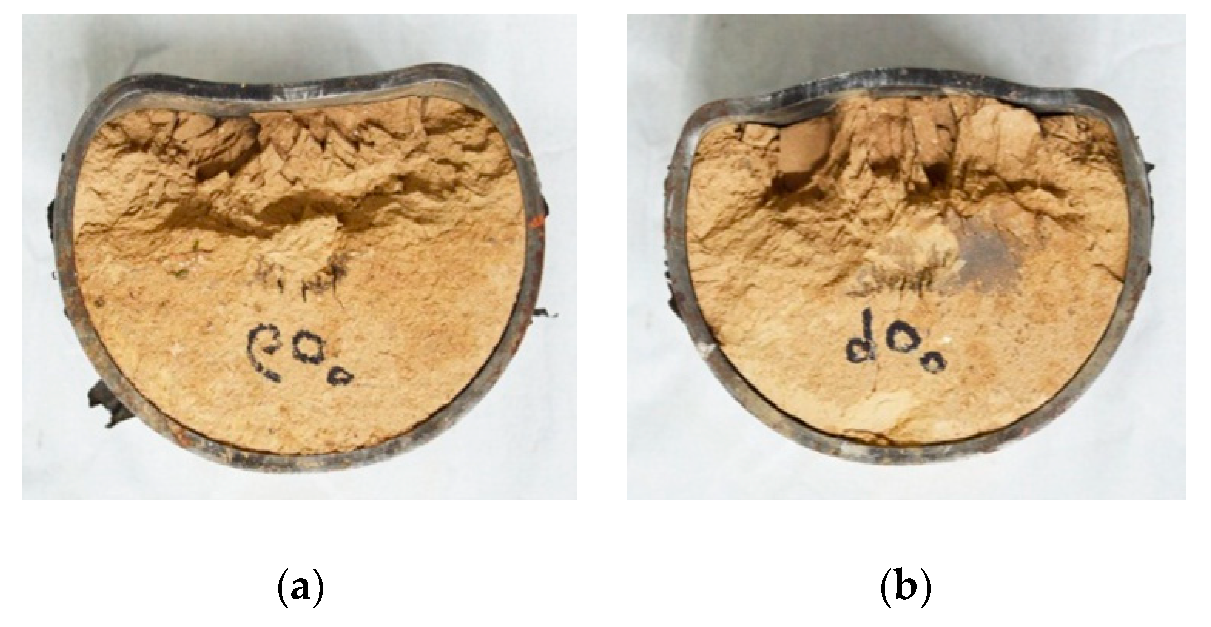
The experimental devices after explosion were recovered, as shown in Figure 12. The data points of the deformed casing contour were extracted using image analysis software GetData, and data processing software Origin was used to compare and analyze the deformed casing surface obtained by the experiment and MATLAB, as shown in Figure 13.
Figure 13 shows that the experiment results coincide well with those obtained by MATLAB, which further illustrates that the MATLAB rapid evaluation program is reasonable. The deforming charge width is also shown to have an effect on the deformation of the filled cylindrical casing. Therefore, we used the MATLAB rapid evaluation program to study the effect of the deforming charge width on the filled cylindrical casing in the remainder of our analysis.
4. Analysis and Discussion of the Results
4.1. Effect of Deforming Charge Width on Filled Cylindrical Casing
For the deformable warheads, the ultimate deformation width of the casing affects the number of effective fragments in the target area, and then affects the damage effectiveness. Based on the above research, the deforming charge width was found to affect the lateral explosive loading range on the casing, and the difference in the range of the load distribution inevitably leads to the difference in the deformed surface of the filled cylindrical casing. If the deforming width is too large, the load generated will be distributed in a wider area, and more casing elements are driven by the lateral explosion. However, the casing elements are fewer. Therefore, the selection of deforming charge width must be appropriate to ensure that the filled cylindrical casing forms a more ideal deformation profile.
In the self-complied MATLAB rapid evaluation program, the deforming charge width is changed by changing the initial load width. In order to study the influence of the deforming charge width on the deformed surface of the filled cylindrical casing, keeping the deforming charge thickness unchanged is necessary, and the thickness of the deforming charge is reflected by the initial loading speed. For this reason, the calculation conditions in this paper include four working conditions with deforming charge widths of 30°, 60°, 90°, and 120° when the initial loading speed is v1. Based on the MATLAB rapid evaluation program, the spatial distributions of the casing elements of the filled cylindrical casing, under different loading widths at several typical moments, were quickly obtained, as shown in Figure 14. In addition, the final deformation surface of the casing corresponding to the four groups of working conditions was arranged as shown in Figure 15.
By analyzing the deformed surface of the casing corresponding to different deforming charge width at different times, as shown in Figure 14 and Figure 15, the following conclusions can be drawn:
- (1)
- If the deforming charge width is too small, the resulting load will be distributed in a relatively narrow region. At this moment, fewer and relatively concentrated casing elements are driven by the lateral explosion, so that the difference in relative azimuth between the casing elements and the circle center is smaller. When velocity decomposition is performed, the velocity in the horizontal direction is larger, and the velocity of the casing elements at the loading region center is slightly larger than those at both ends. As a result, the deformed surface of the casing eventually results in an approximate “inner-concave” type.
- (2)
- If the deforming charge width is too large, the resulting load will be distributed in a relatively wider region, and more casing elements are driven by the lateral explosion. The wide loading region creates a large difference in the relative azimuths of the casing elements and the circle center. The difference in the azimuth angles will cause a greater difference in the velocity decomposition in the horizontal and vertical direction. The closer the casing element to the outside, the greater the velocity of its decomposition in the vertical direction, and the lower in the horizontal direction. Therefore, the final deformation surface is similar to the “outer-convex” type.
- (3)
- As the deforming charge width increases, the deformation surface of the casing gradually transfers from the inner-concave to outer-convex shape. Therefore, we inferred that a suitable width of the deforming charge must exist to make the corresponding deformation surface of the casing D-shaped.
4.2. Relationship between Deforming Dharge Width φ and Criterion α
In practical engineering applications, the size of the missile casing is limited. With reference to the conventional warhead caliber, the range R0 is assumed to be 30 to 150 mm. In addition, according to Equation (7), the relationship between h and R0 can be rewritten as follows:
where h is half of the length of the platform section after deformation (), and R0 is the radius of the initial casing (), as shown in Figure 2b. Thus, in combination with the range of α, the relationship curve between h and R0 can be obtained as shown in Figure 16.
Based on the above analysis, as long as the initial size of the casing is known, the plane width of the casing after deformation corresponding to different values of α can be quickly obtained. However, achieving the optimum deformation profile width is ultimately based on the adjustment of the deforming charge width. Therefore, the main research goal of this section was to quickly determine the optimum deforming charge width under the condition of known initial size of the cylindrical casing.
As seen from the analysis in Section 2.2., the premise is that the length of the entire cylindrical casing in the circumferential direction during the deformation process does not elongate. Thus, the following relationship can be obtained:
where φ represents the deforming charge width and the physical meaning of the other parameters are the same as the previously provided definitions.
According to the range of α and R0, combined with Equations (15) to (18), and using MATLAB for the iterative solution, the optimum deforming charge width corresponding to different α values under different initial casing sizes can be obtained as shown in Table 2.
Through the analysis provided in Table 2, the deforming charge width is not related to the initial casing radius and only to the value of α. In other words, if the value of α is determined, the deforming charge width can be determined rapidly. In order to obtain the relationship between the deforming charge width and the criterion value α, the data in Table 2 were fitted, as shown in Figure 17. As seen from Figure 17, a linear distribution was found between the deforming charge width φ and the value of α, and they have the following relationship:
Note that the physical parameter φ only represents the value of the angle.
In order to verify the accuracy of Equation (19), four groups of different deforming charge widths (φ = 30°, 60°, 90°, and 120°) were designed for comparison with the LS-DYNA simulation results. The simulation results under different deforming charge widths are shown in Figure 18, and the comparison results are shown in Table 3. The results show that Equation (19) can better reflect the relationship between the deforming charge width φ and the value of α, and can provide rapid evaluation of the deformation casing width.
5. Conclusions
The deformable surface of projectile is a key factor to be considered when designing deformable warheads. The final deformation of the casing affects the degree of damage to the target. In order to evaluate the deformable surface width of the cylindrical casing, the criterion α was established and its optimum range was determined to be 20 to 30%. According to our previous theoretical analysis, a rapid evaluation program based on MATLAB was compiled, which was able to rapidly evaluate the projectile deformation surface. The self-compiled MATLAB program was verified using LS-DYNA and experiments; the results showed that our program is scientific and reasonable. Based on the MATLAB rapid evaluation program, the influence of the deforming charge width on the deformed surface of the filled cylindrical casing was determined. The difference in the deforming charge width caused the load distribution to be different, which in turn led to a large difference in the velocity decomposition in the horizontal and vertical directions. As the deforming charge width increased, the deformation surface of the casing gradually transferred from the inner-concave to the outer-convex shape. Therefore, we inferred that a suitable deforming charge width must exist that can form the corresponding deformation surface into a D-shape.
In addition, a formula that better reflects the relationship between the deforming charge width φ and the criterion value α was fitted. In order to verify the accuracy of the fitting formula, four groups of different deforming charge widths were designed for comparison with the LS-DYNA simulation results; the results showed that the fitting formula coincides well with the simulation results and can provide rapid guidance for the structural design of deformable warheads.
Author Contributions
L.D. introduced the research ideas of this article, designed the experiments, and wrote the paper; Z.L. conducted the experiments and collected the experimental data; F.L. was responsible for proofreading, and analyzed the simulation and experimental results; X.L. was responsible for compiling the MATLAB program and numerical simulation.
Funding
This research was funded by the National Natural Science Foundation of China (grant Nos. 11202237 and 11132012).
Acknowledgments
The authors would like to thank the academic and technical staff in the Laboratory of Light Gas Gun, which is affiliated with the National University of Defense Technology, for their experiment and simulation support.
Conflicts of Interest
The authors declare no conflict of interest.
References
- Kempton, M.L. Selectively Aimable Warhead. U.S. Patent 4,026,213, 31 May 1977. [Google Scholar]
- Konig, P.J.; Mostert, F.J. The Results of a Deformable Warhead Technology Exercise. In Proceedings of the 20th International Symposium on Ballistics (ISB’20), Orlando, FL, USA, 23–27 September 2002. [Google Scholar]
- Lloyd, R.M. Conventional Warhead Systems Physics and Engineering Design; American Institute of Aeronautics and Astronautics: Washington, DC, USA, 1998. [Google Scholar]
- Fairlie, G.E.; Marriott, C.O.; Robertson, N.J.; Livingstone, I.; Birnbaum, N. Computer Modelling of Full Size Fragmenting Aimable Warheads Using AUTODYN-3D. In Proceedings of the 17th International Symposium on Ballistics (ISB’17), Midrand, South Africa, 23–27 March 1998. [Google Scholar]
- Tennyson, R.C. The Effect of Shape Imperfection and Stiffening on the Buckling of Circular Cylinders. In Buckling of Structures; Springer: Berlin, Germany, 1976; pp. 251–273. [Google Scholar]
- Lindberg, H.E.; Florence, A.L. Dynamic Pulse Buckling; Martinus Nijhoff Publishers: Leiden, The Netherlands, 1987. [Google Scholar]
- Gefken, P.R.; Kirkpatric, S.W.; Hoimes, B.S. Response of Impulsively Loaded Cylindrical Shells. Int. J. Impact Eng. 1988, 7, 213–227. [Google Scholar] [CrossRef]
- Kirkpatric, S.W.; Hoimes, B.S. Structural Response of Thin Cylindrical Shells Subjected to Impulsive External Loads. AIAA J. 1988, 26, 96–103. [Google Scholar] [CrossRef]
- Yakupov, R.G. Plastic Deformations of a Cylindrical Shell under the Action of a Planar Explosion Wave. J. Appl. Mech. Tech. Phys. 1982, 14, 579–584. [Google Scholar] [CrossRef]
- Yakupov, R.G. Plastic Strains in a Cylindrical Shell under the Effect of a Spherical Blast Wave. Strength Mater. 1982, 14, 52–56. [Google Scholar] [CrossRef]
- Wierzbicki, T.; Hoo Fatt, M.S. Damage Assessment of Cylinders due to Impact and Explosive Loading. Int. J. Impact Eng. 1993, 13, 215–244. [Google Scholar] [CrossRef]
- Hoo Fatt, M.S.; Wierzbicki, T. Damage of Plastic Cylinders under Localized Pressure Loading. Int. J. Mech. Sci. 1991, 33, 999–1016. [Google Scholar] [CrossRef]
- Hu, G.Y.; Xia, G.; Li, J. The Transient Responses of Two-Layered Cylindrical Shells Attacked by Underwater Explosive Shock Waves. Compos. Struct. 2010, 92, 1551–1560. [Google Scholar]
- Yao, X.L.; Guo, J.; Feng, L.H.; Zhang, A.M. Comparability Research on Impulsive Response of Double Stiffened Cylindrical Shells Subjected to Underwater Explosion. Int. J. Impact Eng. 2009, 36, 754–762. [Google Scholar] [CrossRef]
- Li, J.; Rong, J.L. Experimental and Numerical Investigation of the Dynamic Response of Structures Subjected to Underwater Explosion. Eur. J. Mech. B/Fluids 2012, 32, 59–69. [Google Scholar] [CrossRef]
- Hung, C.F.; Lin, B.J.; Hwang-Fuu, J.J.; Hsu, P.Y. Dynamic Response of Cylindrical Shell Structures Subjected to Underwater Explosion. Ocean Eng. 2009, 36, 564–577. [Google Scholar] [CrossRef]
- Ma, X.Q.; Stronge, W.J. Spherical Missile Impact and Perforation of Filled Tubes. Int. J. Impact Eng. 1988, 3, 1–16. [Google Scholar]
- Neilson, A.J.; Howe, W.D.; Garton, G.P. Impact Resistance of Mild Steel Pipes: An Experimental Study; UKAEA Atomic Energy Establishment AEEW-R-2125: Abingdon, UK, 1987. [Google Scholar]
- Li, Z.; Zhang, S.Y.; Yang, G.T. The Global Deformation and Local Damage Analysis of Filled Metallic Cylindrical Shells Impact by Missiles. Acta Mech. Solida Sin. 1999, 20, 303–309. [Google Scholar]
- Jama, H.H.; Nurick, G.N.; Bambach, M.R.; Grzebieta, R.H.; Zhao, X.L. Steel Square Hollow Sections Subjected to Transverse Blast Loads. Thin-Walled Struct. 2012, 53, 109–122. [Google Scholar] [CrossRef]
- Li, L.J.; Jiang, W.K.; Ai, Y.H. Experimental Study on Deformation and Shock Damage of Cylindrical Shell Structures Subjected to Underwater Explosion. Proc. Inst. Mech. Eng. Part C J. Mech. Eng. Sci. 2010, 224, 2505–2514. [Google Scholar] [CrossRef]
- Ding, L.L.; Li, X.Y.; Lu, F.Y.; Zhang, S.X.; Li, X.Y. Research on Deformation Mechanism of Cylindrical Shell Filled with Medium under Lateral Explosion Loading. Acta Armamentarii 2017, 38, 24–29. [Google Scholar]
- Ding, L.L.; Li, Z.D.; Liang, M.Z.; Li, X.Y.; Lu, F.Y. The Dispersion Rule of Fragments about the Asymmetric Shell. Shock Vib. 2017, 2017, 9810978. [Google Scholar] [CrossRef]
- Ding, L.L.; Li, Z.D.; Lu, F.Y.; Li, X.Y. Research into the Energy Output of Asymmetric Cylindrical Structure under Internal Explosion Loading. Energies 2018, 11, 967. [Google Scholar] [CrossRef]
- Ding, L.L.; Li, Z.D.; Lu, F.Y.; Li, X.Y. Rapid Assessment of the Spatial Distribution of Fragments about the D-Shaped Structure. Adv. Mech. Eng. 2018, 10, 1–16. [Google Scholar] [CrossRef]
- Li, X.Y.; Li, Z.D.; Liang, M.Z. An Analytical Approach for Deformation Shapes of a Cylindrical Shell with Internal Medium Subjected to Lateral Contact Explosive Loading. Math. Probl. Eng. 2015, 2015, 563097. [Google Scholar] [CrossRef]
- Beijing Institute of Technology «explosion and its effects» Compile Group. Explosion and Its Effects; National Defense Industry Press: Beijing, China, 1979; pp. 257–263. [Google Scholar]
Figure 1.
Schematic diagram and action process of the deformable warhead. (A) Initial projectile structure; (B) Deforming charge detonation; (C) D-shaped projectile surface; (D) Fragments directional dispersion.
Figure 1.
Schematic diagram and action process of the deformable warhead. (A) Initial projectile structure; (B) Deforming charge detonation; (C) D-shaped projectile surface; (D) Fragments directional dispersion.
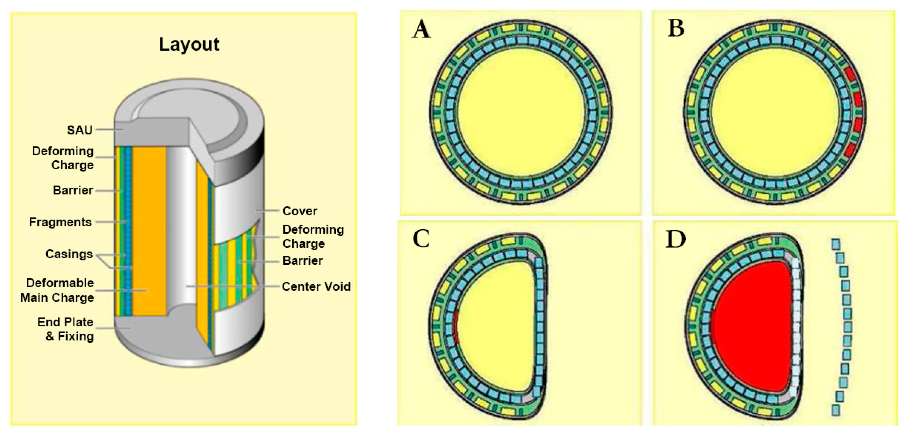
Figure 2.
Schematic diagram of the casing element after deformation and the D-shaped profile. (a) Casing element and (b) D-shaped profile.
Figure 2.
Schematic diagram of the casing element after deformation and the D-shaped profile. (a) Casing element and (b) D-shaped profile.
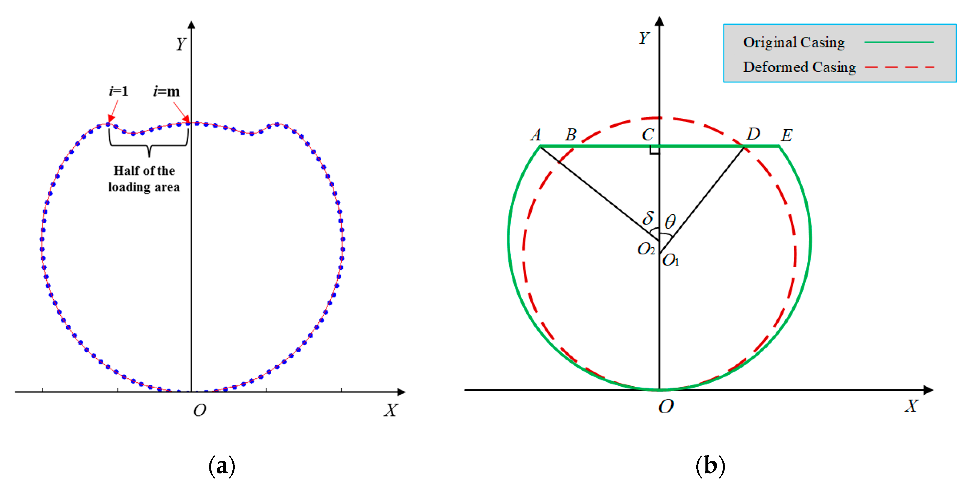
Figure 3.
The proportion of straight segment and arc segment under different center angles.

Figure 4.
Cross-sectional view of (a) D-90° and (b) D-120° structures.
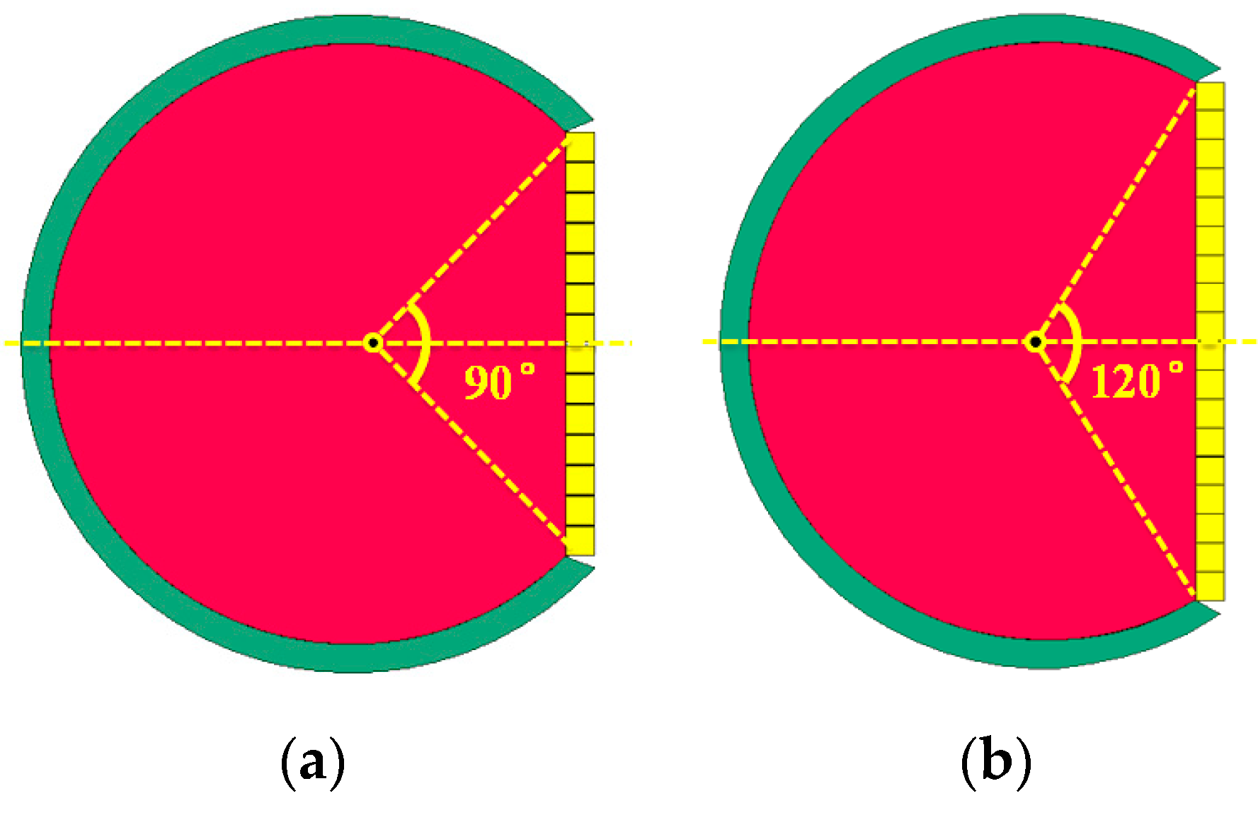
Figure 5.
Relationships between the energy distribution and azimuth angle. (a) Total energy of fragments varies with azimuth angle; (b) Energy density of fragments varies with azimuth angle.
Figure 5.
Relationships between the energy distribution and azimuth angle. (a) Total energy of fragments varies with azimuth angle; (b) Energy density of fragments varies with azimuth angle.
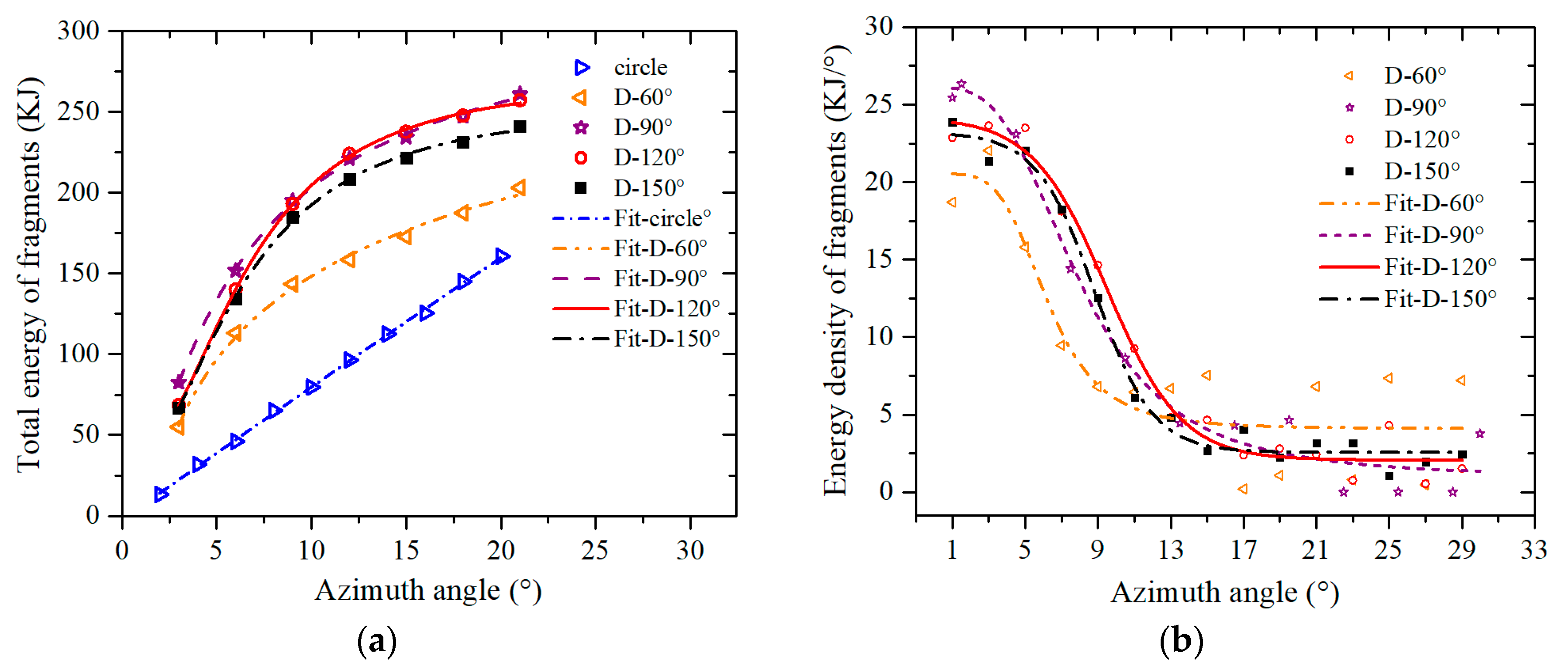
Figure 6.
Schematic diagram of the unit length loading area. The mass of Plane 1 per unit length m1: m1 = ρ1t1L; The mass of Plane 2 per unit length m2: m2 = ρ2t2L; The mass of deforming charge per unit length m0: m0 = ρ0t0L; The total energy released by unit length deforming charge E: E = m0Qv.
Figure 6.
Schematic diagram of the unit length loading area. The mass of Plane 1 per unit length m1: m1 = ρ1t1L; The mass of Plane 2 per unit length m2: m2 = ρ2t2L; The mass of deforming charge per unit length m0: m0 = ρ0t0L; The total energy released by unit length deforming charge E: E = m0Qv.
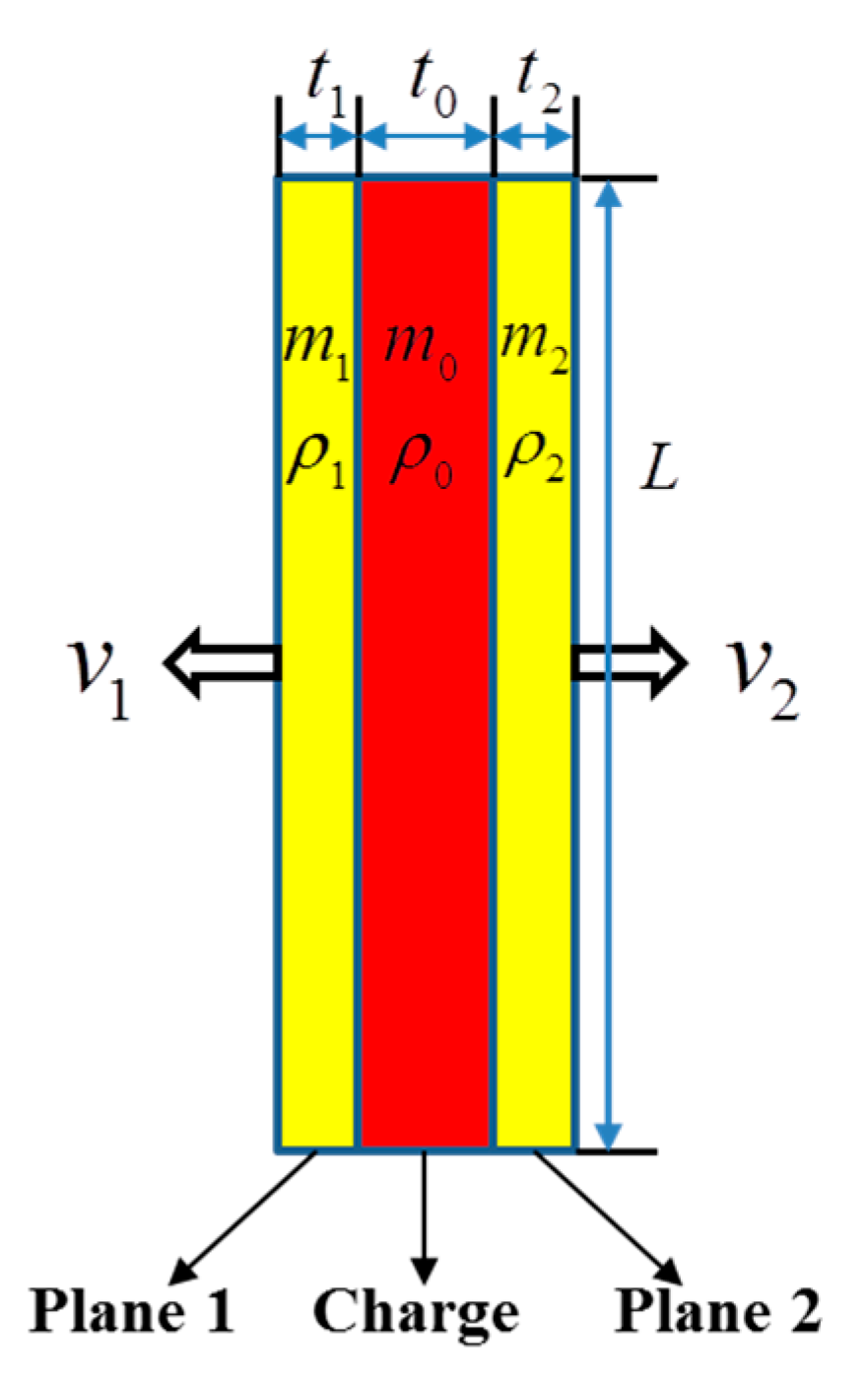
Figure 7.
Schematic diagram of the structure of simulation.
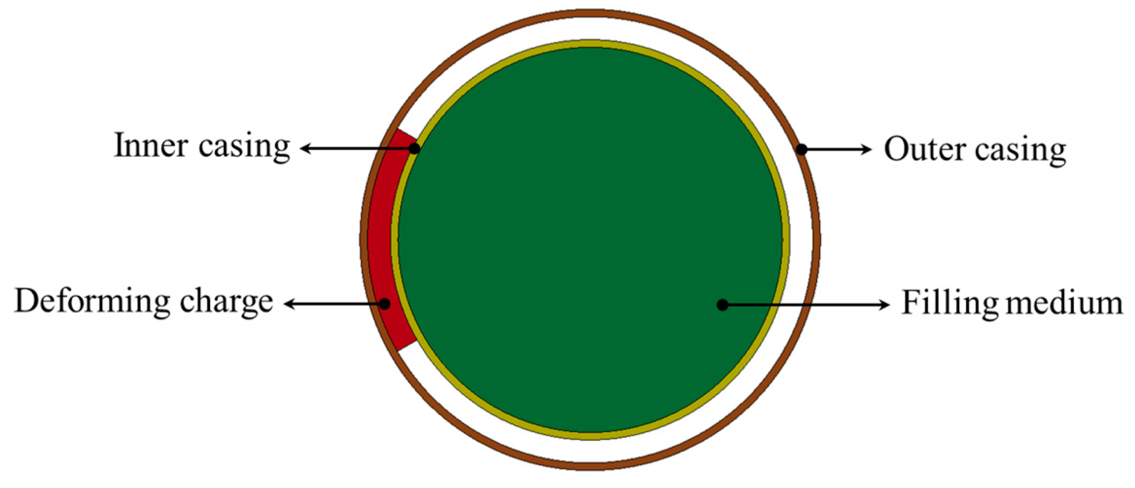
Figure 8.
Deformed surface of the inner casing under several typical moments obtained from MATLAB: (a) t = 50 μs; (b) t = 100 μs; (c) t = 150 μs.
Figure 8.
Deformed surface of the inner casing under several typical moments obtained from MATLAB: (a) t = 50 μs; (b) t = 100 μs; (c) t = 150 μs.
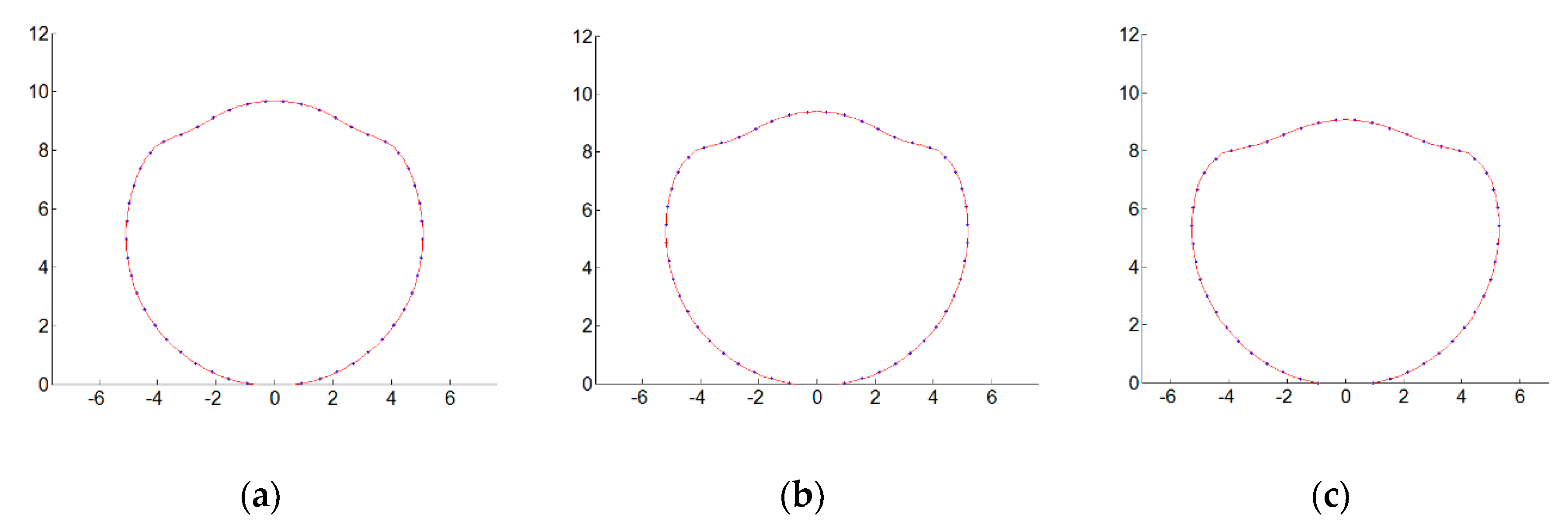
Figure 9.
Deformed surface of the inner casing under several typical moments obtained from LS-DYNA: (a) t = 50 μs; (b) t = 100 μs; (c) t = 150 μs.
Figure 9.
Deformed surface of the inner casing under several typical moments obtained from LS-DYNA: (a) t = 50 μs; (b) t = 100 μs; (c) t = 150 μs.
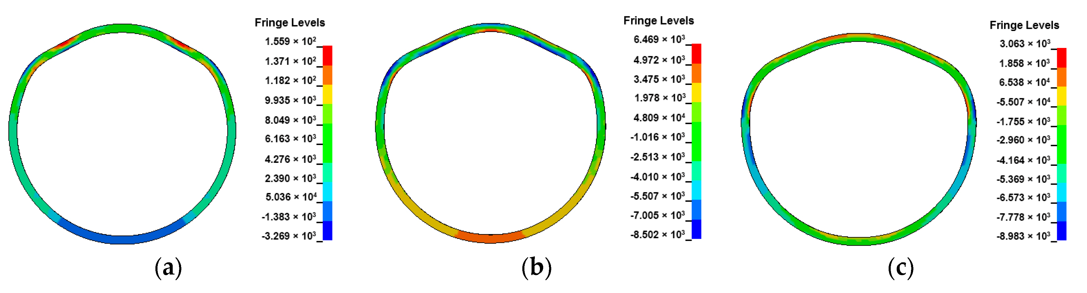
Figure 10.
Various parts of the experimental device: (a) upper end-plate; (b) lower end-plate; (c) filling medium; (d) inner casing; (e) outer casing.
Figure 10.
Various parts of the experimental device: (a) upper end-plate; (b) lower end-plate; (c) filling medium; (d) inner casing; (e) outer casing.
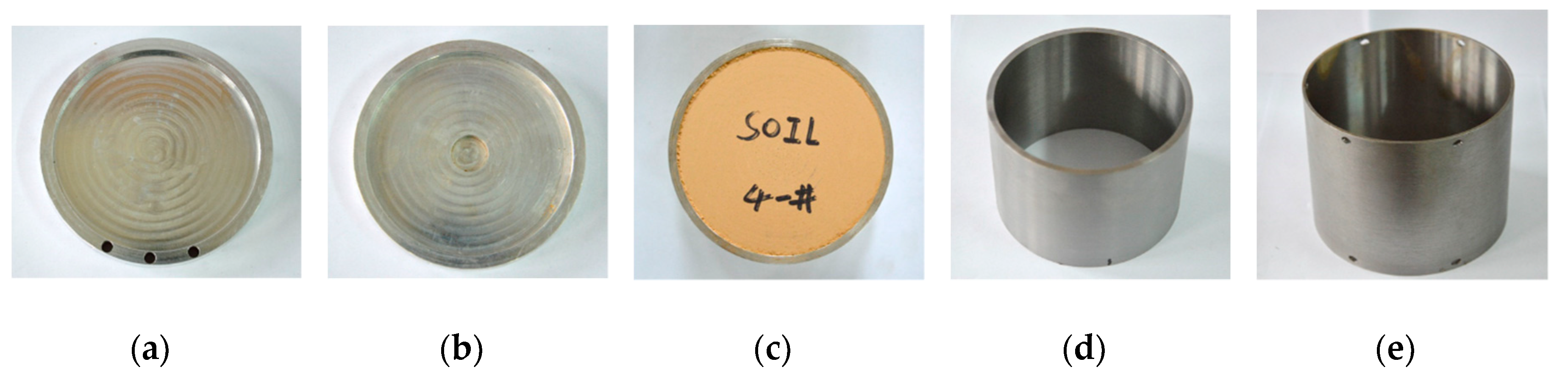
Figure 11.
Experiment preparation process: (a) filling of inner medium; (b) adhesion of deforming charge; (c) installation of detonating cord; (d) assembly of outer casing; (e) installation of electric detonator.
Figure 11.
Experiment preparation process: (a) filling of inner medium; (b) adhesion of deforming charge; (c) installation of detonating cord; (d) assembly of outer casing; (e) installation of electric detonator.
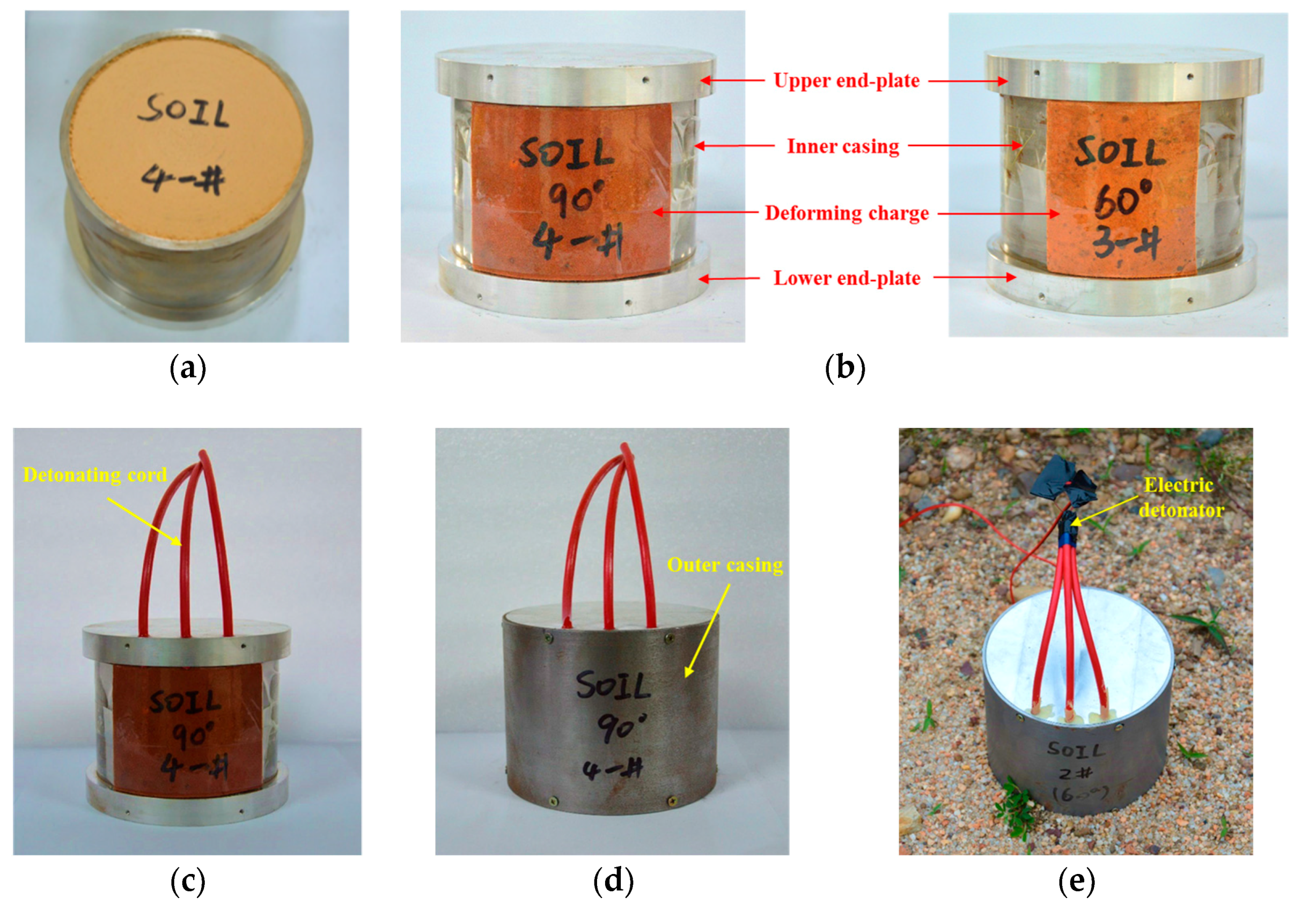
Figure 12.
Experiment results for different deforming charge widths: (a) φ = 60°; (b) φ = 90°.

Figure 13.
Comparison of deformed casing profile based on the experiment and MATLAB results. (a) φ = 60°; (b) φ = 90°.
Figure 13.
Comparison of deformed casing profile based on the experiment and MATLAB results. (a) φ = 60°; (b) φ = 90°.
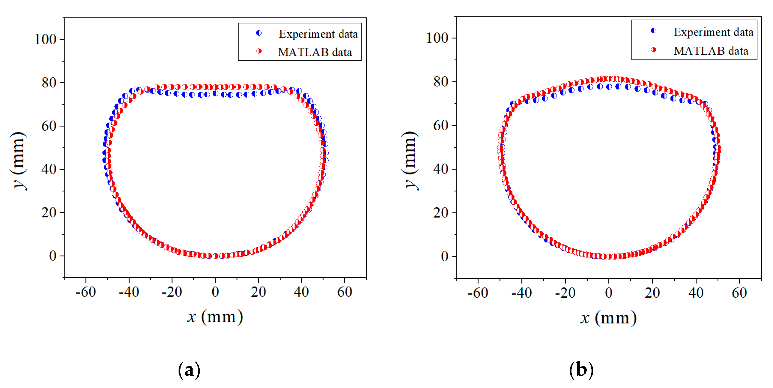
Figure 14.
Spatial distribution of the casing elements of the filled cylindrical casing under different loading widths at several typical moments: (a) φ = 30°; (b) φ = 60°; (c) φ = 90°; (d) φ = 120°.
Figure 14.
Spatial distribution of the casing elements of the filled cylindrical casing under different loading widths at several typical moments: (a) φ = 30°; (b) φ = 60°; (c) φ = 90°; (d) φ = 120°.

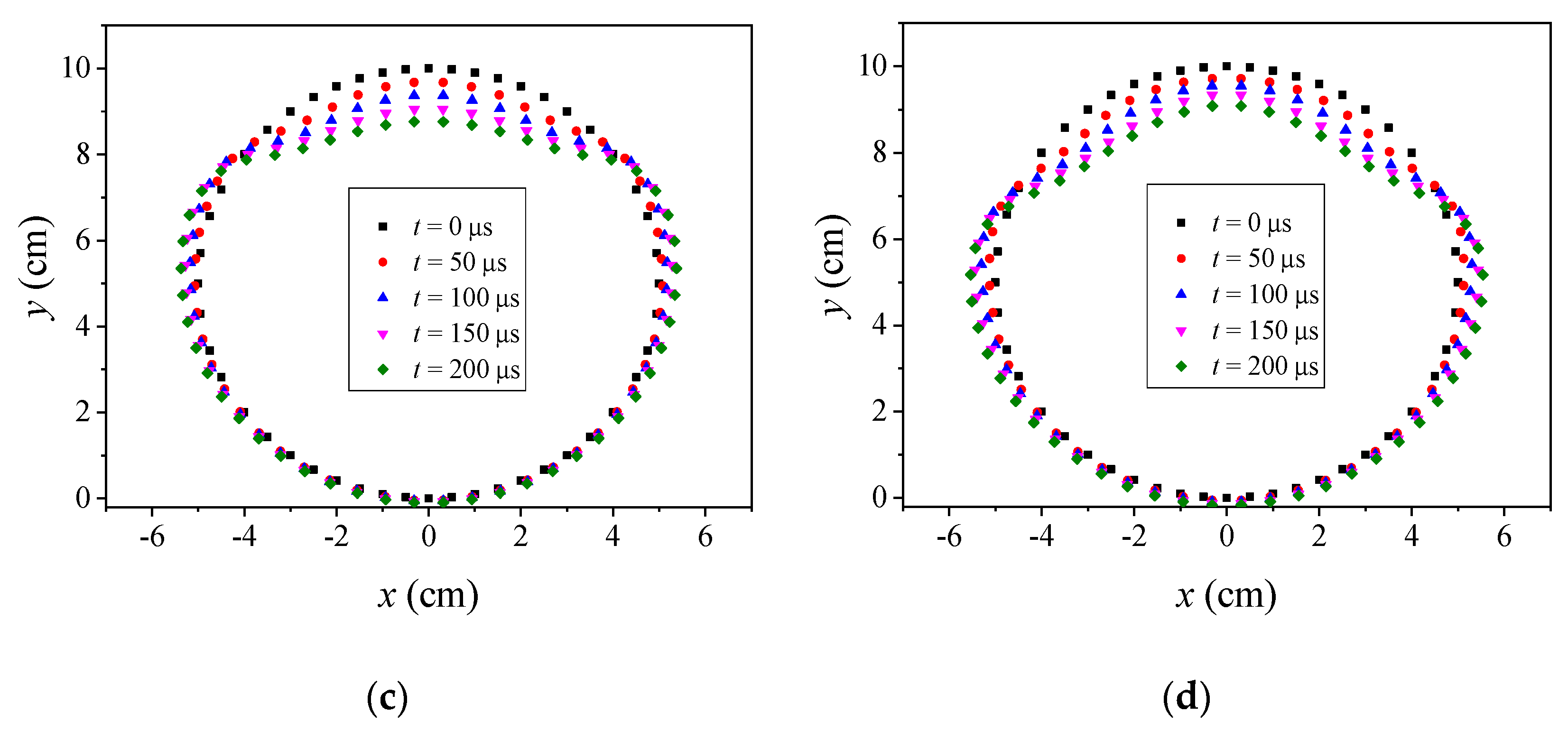
Figure 15.
The final deformation surface of the casing corresponding to the four groups of working conditions.
Figure 15.
The final deformation surface of the casing corresponding to the four groups of working conditions.
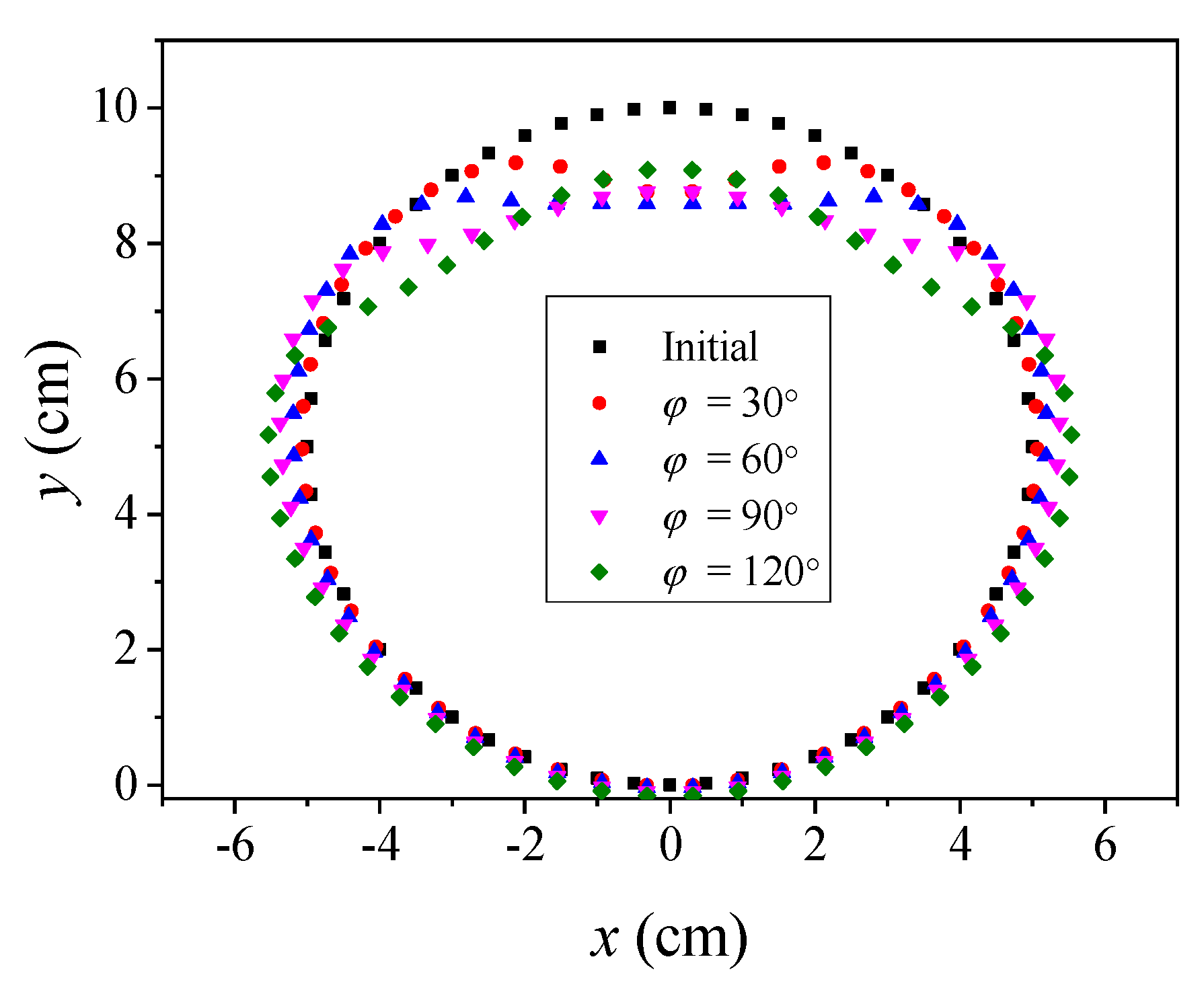
Figure 16.
Relationship curve between half of the length of the platform section after deformation h and radius of the initial casing R0.
Figure 16.
Relationship curve between half of the length of the platform section after deformation h and radius of the initial casing R0.
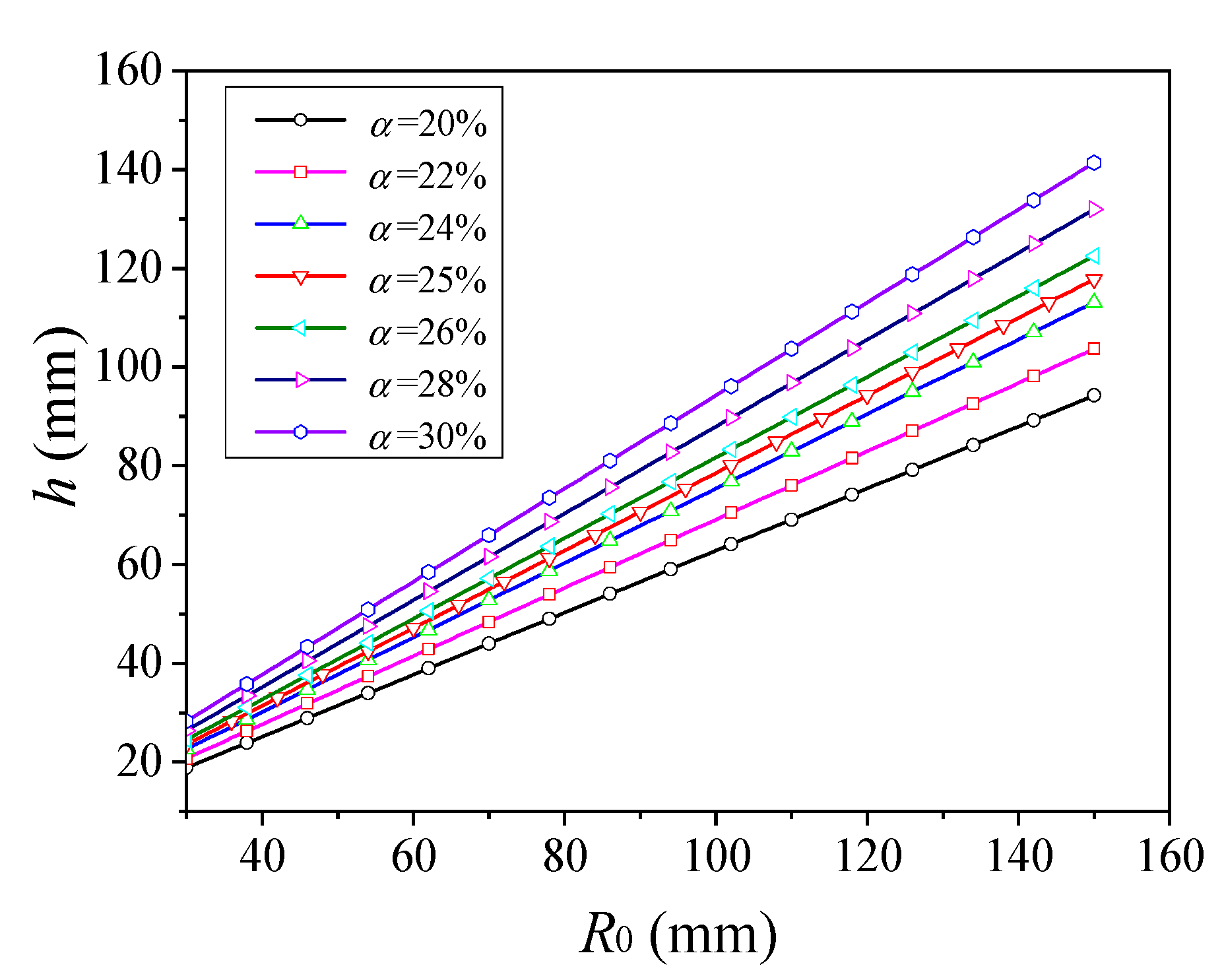
Figure 17.
Relationship between the criterion α and the deforming charge width φ.

Figure 18.
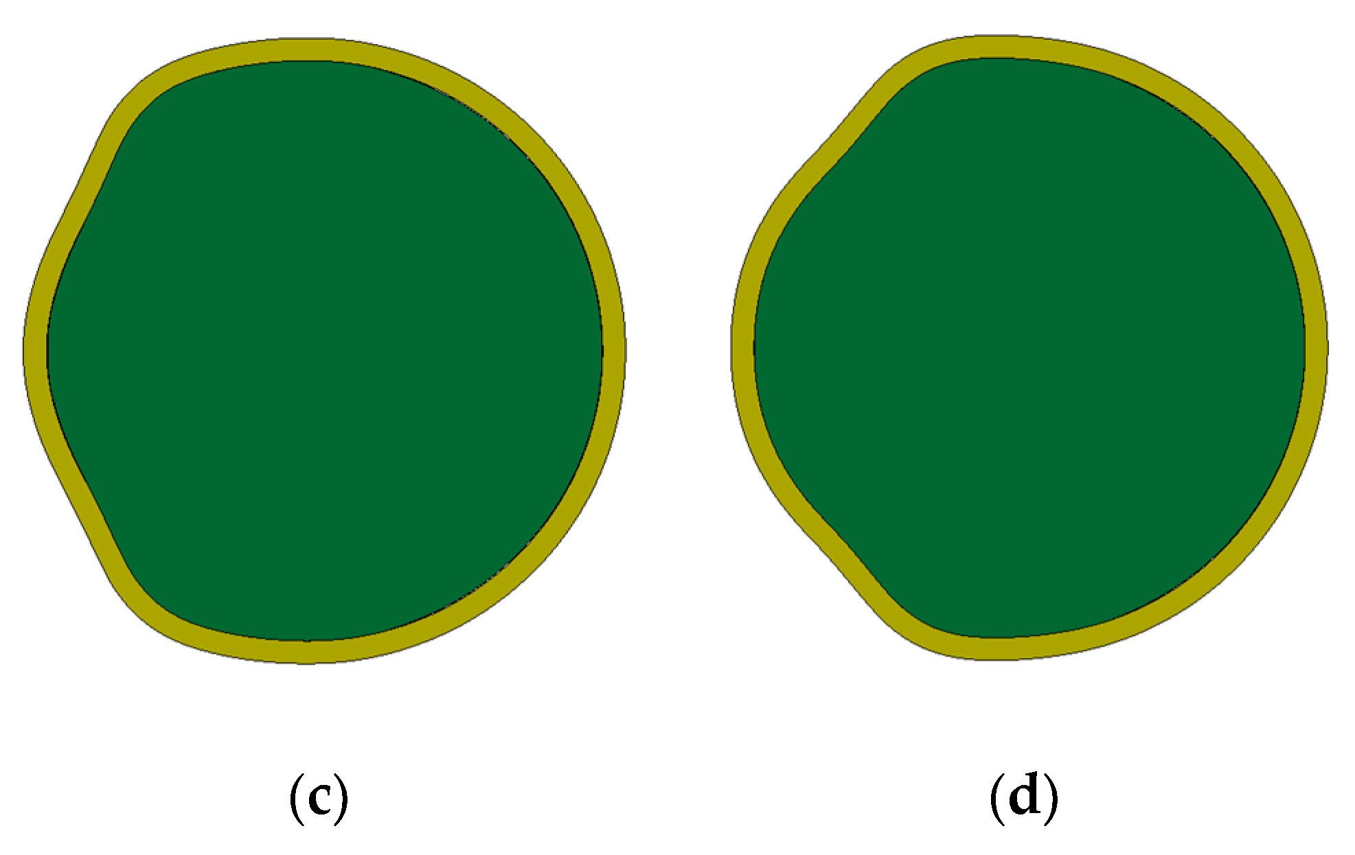
Deformation surface of the casing under different deforming charge widths: (a) φ = 30° (α = 17.8%); (b) φ = 60° (α = 24.1%); (c) φ = 90° (α = 31.2%); (d) φ = 120° (α = 38.4%).
Figure 18.
Deformation surface of the casing under different deforming charge widths: (a) φ = 30° (α = 17.8%); (b) φ = 60° (α = 24.1%); (c) φ = 90° (α = 31.2%); (d) φ = 120° (α = 38.4%).


Table 1.
The specific parameters of each part corresponding to the five groups of conditions.
| D-Shaped | Radius of Initial Casing | Length of Straight Segment | Length of Arc Segment | Proportion of Straight Segment β |
|---|---|---|---|---|
| D-30° | 5.05 cm | 2.61 cm | 29.09 cm | 8.2% |
| D-60° | 5.05 cm | 5.05 cm | 26.44 cm | 16.1% |
| D-90° | 5.05 cm | 7.14 cm | 23.79 cm | 22.8% |
| D-120° | 5.05 cm | 8.75 cm | 21.15 cm | 29.2% |
| D-150° | 5.05 cm | 9.76 cm | 18.51 cm | 34.5% |
Table 2.
The optimum deforming charge width under different initial casing sizes.
| Initial Radius of Casing | Width of Deforming Charge φ | |||||
|---|---|---|---|---|---|---|
| R0 (mm) | α = 20% | α = 22% | α = 24% | α = 26% | α = 28% | α = 30% |
| 30 | 46° | 53° | 60° | 69° | 77° | 85° |
| 40 | 46° | 53° | 60° | 69° | 77° | 85° |
| 50 | 46° | 53° | 60° | 69° | 77° | 85° |
| 60 | 46° | 53° | 60° | 69° | 77° | 85° |
| 70 | 46° | 53° | 60° | 69° | 77° | 85° |
| 80 | 46° | 53° | 60° | 69° | 77° | 85° |
| 90 | 46° | 53° | 60° | 69° | 77° | 85° |
| 100 | 46° | 53° | 60° | 69° | 77° | 85° |
| 110 | 46° | 53° | 60° | 69° | 77° | 85° |
| 120 | 46° | 53° | 60° | 69° | 77° | 85° |
| 130 | 46° | 53° | 60° | 69° | 77° | 85° |
| 140 | 46° | 53° | 60° | 69° | 77° | 85° |
| 150 | 46° | 53° | 60° | 69° | 77° | 85° |
Table 3.
Comparison results between simulation and calculation.
| Width of Deforming Charge φ | α | |
|---|---|---|
| Simulation Result (LS-DYNA) | Calculation Result from Equation (19) | |
| 30° | 0.178 | 0.161 |
| 60° | 0.241 | 0.237 |
| 90° | 0.312 | 0.313 |
| 120° | 0.384 | 0.389 |
© 2018 by the authors. Licensee MDPI, Basel, Switzerland. This article is an open access article distributed under the terms and conditions of the Creative Commons Attribution (CC BY) license (http://creativecommons.org/licenses/by/4.0/).
Share and Cite
MDPI and ACS Style
Ding, L.; Li, Z.; Lu, F.; Li, X. Rapid Evaluation and Analysis of the Deformation of Filled Cylindrical Casing with Deforming Charge Width Based on Self-Compiled MATLAB Program. Symmetry 2018, 10, 310. https://doi.org/10.3390/sym10080310
AMA Style
Ding L, Li Z, Lu F, Li X. Rapid Evaluation and Analysis of the Deformation of Filled Cylindrical Casing with Deforming Charge Width Based on Self-Compiled MATLAB Program. Symmetry. 2018; 10(8):310. https://doi.org/10.3390/sym10080310
Chicago/Turabian StyleDing, Liangliang, Zhenduo Li, Fangyun Lu, and Xiangyu Li. 2018. "Rapid Evaluation and Analysis of the Deformation of Filled Cylindrical Casing with Deforming Charge Width Based on Self-Compiled MATLAB Program" Symmetry 10, no. 8: 310. https://doi.org/10.3390/sym10080310
Note that from the first issue of 2016, this journal uses article numbers instead of page numbers. See further details here.