An Experimental Study of Hydraulic Jump in a Gradually Expanding Rectangular Stilling Basin with Roughened Bed


1
Department of Water Engineering, University of Tabriz, Tabriz 5166616471, Iran
2
Department of Civil, Architectural and Environmental Engineering, University of Napoli Federico II, Napoli 80125, Italy
*
Author to whom correspondence should be addressed.
Water 2017, 9(12), 945; https://doi.org/10.3390/w9120945
Submission received: 25 August 2017
/
Revised: 28 November 2017
/
Accepted: 30 November 2017
/
Published: 7 December 2017
Abstract
:The paper presents the results of an experimental study carried out to investigate the effect of geometric and hydraulic parameters on energy dissipation and location of the hydraulic jump, with a change in the height of roughness elements and the divergence of walls in different discharges. Experiments were conducted in a horizontal rectangular basin with gradual expansion 0.5 m wide and 10 m long. Four physical models were fixed in the flume. The measured characteristics of the hydraulic jump with different divergences ratio (B = b1/b2 = 0.4, 0.6, 0.8, 1) and the inflow Froude numbers (6 < Fr1 < 12) were compared with each other and with the corresponding values measured for the classical hydraulic jump. The results showed that the tailwater depth required to form a hydraulic jump and also the roller length of the hydraulic jump and the length of the hydraulic jump on a gradual expansion basin with the rough bed were appreciably smaller than that of the corresponding hydraulic jumps in a rectangular basin with smooth and rough bed. With the experimental data, empirical formulae were developed to express the hydraulic jump characteristics relating to roughness elements height and divergence ratio of wall. Also, the applicability of some empirical relationships for estimating the roller length was tested.
1. Introduction
In an open channel, a hydraulic jump is a sudden and rapid transition from a supercritical to a subcritical flow. The transition is an extremely turbulent flow associated with the development of large-scale turbulence, surface waves and spray and air entrainment, and it is characterized by strong dissipative processes [1]. The hydraulic jump is often applied as an energy dissipator below weirs or spillways of dams, chutes, gates, drops and other structures might be utilized in this regards. In the hydraulic jump, the water depth increases abruptly and some of the kinetic energy is transformed into potential energy, with some energy irreversibly losses through the turbulence. Determining the dimensions of the stilling basin is an important task for the hydraulic engineers to design a safe and economical energy dissipator.
The first main experimental and theoretical works about the hydraulic jump were conducted by Bidone (1819) and Bélanger (1841). Bélanger (1841) developed a theoretical solution for the ratio of the conjugate depths based upon the momentum principle [2]:
where is the inflow depth, is the sequent depth of the flow and is the inflow Froude number () in which is the inflow velocity and g is the gravitational acceleration. This equation is valid only for a smooth horizontal rectangular channel.
Harleman (1959) showed that the sequent depth ratio values were lower for high inflow Froude numbers than those predicted by Bélanger’s equation [3]. Gill [4] also found that the sequent depth ratio was over estimated if the channel boundary flow resistance was neglected. The classical hydraulic jump was studied extensively by Peterka [5], Rajaratnam [6], Leutheusser and Kartha [7], McCorquodale and Khalifa [8], Hager and Bremen [9], Hager [10], Wu and Rajaratnam [11] and CarolloFerro [3]. Bubbly two-phase flow in a hydraulic jump using a flow visualization technigue were studied by Mossa and Tolve [12]. The air-water flow properties in a hydraulic jump were extensively studied Gualtieri and Chanson [13], Chanson and Gualtieri [14], Gualtieri and Chanson [15] and Gualtieri and Chanson [16].
A preliminary investigation by Rajaratnam [17] indicated that the tailwater depth (y2) required to form a hydraulic jump on rough bed could be appreciably smaller than the corresponding sequent depth on the smooth bed () [18]. Rajaratnam [17] found that the hydraulic jump on rough beds were significantly shorter than the classical hydraulic jump on smooth bed [18]. Hughes and Flack [19] measured hydraulic jump characteristics over several artificially roughened beds in a horizontal rectangular flume with smooth side walls. Their observations showed that boundary roughness reduces both the sequent depth and the length of a hydraulic jump and that the observed reductions were related to both the inflow Froude number and the degree of roughness. Ead and Rajaratnam [18] analyzed the hydraulic jump on a corrugated bed and identified substantial axial velocity profile similitude at different cross sections of the hydraulic jump. The effect of the tailwater level on flow conditions at the hydraulic jump were studied by Mossa et al. [20]. The experimental results showed that, design stilling basins with abrupt drops may be used to stabilize the position of the jump. Pagliara et al. [21] conducted many laboratory tests in order to propose empirical relationships to predict the main hydraulic jump characteristics on a rough uniform and non-homogeneous granular bed material. Oscillating characteristics and cyclic mechanisms of the hydraulic jump was studied by Mossa [22]. The results showed that the vortex roll-up process was linked to fluctuations of the longitudinal location of the jump toe.
Stilling basin may be damaged as a result of cavitation, abrasion or combination of both. Cavitation is possible wherever boundary irregularities cause a separation of flow with resultant localized pressure drops. In order to prevent cavitation, the bed surface must be smooth or roughness elements must be placed in such a way that their crests are at the upstream bed level, and they do not protrude into the flow [18]. Stilling basin can be made gradually or abruptly expanding eventually extended by appurtenances. These not only dissipate additional energy and reduce the basin length, but also deflect the high-velocity jets away from the basin bottom. The first study about hydraulic jump in trapezoidal stilling basins must be credited to Posey and Hasing (1938), who studied the effect of side slope on the sequent depth and the length of hydraulic jump. They found that the sequent depths ratio as observed compares well with the prediction based on the conventional momentum approach. Also, they showed that decreasing side slope increased the length of the hydraulic jump in comparison with the hydraulic jump in stilling basins of rectangular cross-section [23].
Chanson and Carvalho [1] using an integral form of the continuity and the momentum principles, proposed Equation (2) for calculating the sequent depth ratio of the hydraulic jump in an irregular channel.
where A1 and A2 are the flow cross-sectional area, upstream and downstream of the hydraulic jump, respectively. B′ is a characteristics free-surface width (B1 < B′ < B2), B1 and B2 are the upstream and downstream free-surface widths, respectively. Here the inflow Froude number Fr1 is and B is another free-surface width maybe defined as:
where d1 is the inflow depth of the hydraulic jump and d2 is the flow depth downstream of the hydraulic jump. For a rectangular channel, Equation (2) becomes the Bélanger equation. To date a large number of stilling basin types has been proposed. The usual stilling basin is characterized by a (gradual or abrupt) enlargement of the channel width in order to raise its efficiency. Hager [24] studied the characteristics of the hydraulic jump in non-prismatic rectangular channels. The results showed that the hydraulic jump in a diverging channel needs lower tailwater flow depth for identical flow conditions. Also, he obtained that the length characteristics were nearly independent of the width ratio and had the same order of magnitude as in prismatic channels. Lawson and Phillips [25] used the momentum analysis of Koloseus and Ahmad (1969), Arbhabhirama and Abella [26] and France (1981) adopted to obtain a suitable circular hydraulic jump equation. The results showed that the length of the circular hydraulic jump was found to be considerably less than that of a corresponding rectangular hydraulic jump. The head loss in a circular hydraulic jump was greater than in a rectangular jump for the same inflow Froude number.
A theoretical equation for the relative sequent depths of a hydraulic jump in a trapezoidal cross-section was suggested by Diskin [27]. Arbhabhirama and Abella [26] studied radial hydraulic jumps in a gradually expanding channel of rectangular cross section with divergence angles from 0 to 13°. They assumed a quarter of an ellipse for the water surface profile along the length of the hydraulic jump. They developed some relationships to calculate the sequent depths and relative energy loss by applying the continuity and momentum equations. The results showed that the divergence of the walls causes reductions in the sequent depth and the length of jump and an increase in the energy loss as compared to the hydraulic jump in a straight rectangular channel. Wanoschek and Hager [23] investigated the properties of a hydraulic jump in a trapezoidal channel with a side slope of 1:1 experimentally. They found that the sequent depth decreased and the energy loss increased when compared with the usual hydraulic jump in a rectangular basin.
The most recent research study regarding some properties of the hydraulic jump in expanding channels with trapezoidal cross-sections was carried out by Omid et al. [28]. The divergent angle in their study ranged from 3° to 9°. They found that the sequent depth and the length of the hydraulic jump decreased, whereas the energy loss increased with the increasing bottom width. Compared to a prismatic stilling basin, an expanding basin modifies not only the sequent depths but also influences all the other flow characteristics.
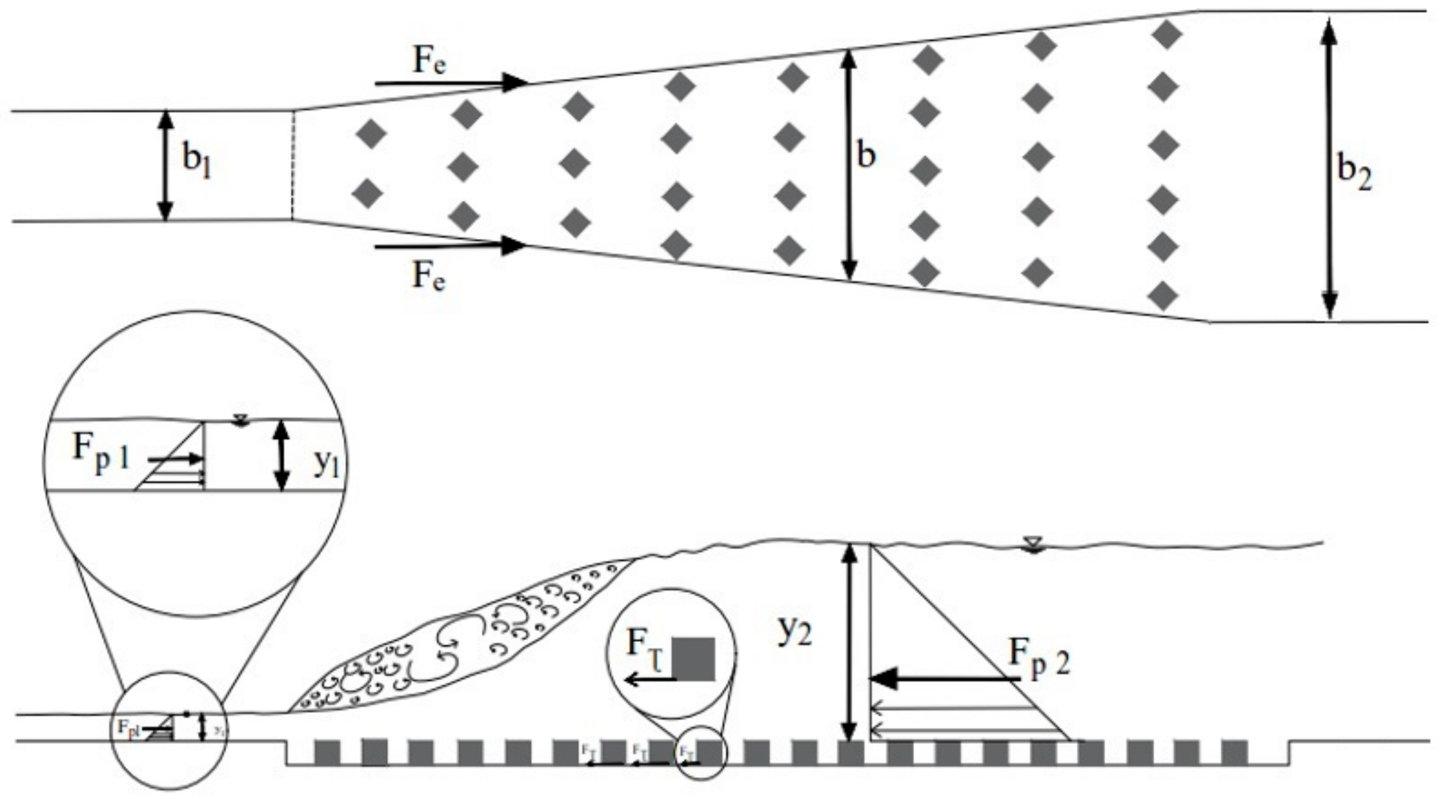
The increase of the bed shear stress is the main cause for reduction of the sequent depth and the length of the hydraulic jump over the rough bed. The bed shear stress of the hydraulic jump on a rough bed of channel with expansion walls can be calculated by using the integral momentum equation. The momentum equation with the nomenclature of the Figure 1 can be written as:
where b is the width of the channel where the hydraulic jump ends. Fp1, Fp2, M1 and M2 are the pressure forces and the momentum upstream and downstream of the hydraulic jump, respectively, is the integrated bed shear stress on the horizontal plane and Fe is pressure force on the expanding wall [29]. If the pressure force on the expansion walls is negligible, Equation (4) can be written as [29]:
In an expanded basin usually two problems are faced, one is the determination of the sequent depth and the other is the estimation of the energy loss [30]. Past experimental studies are listed in Table 1.
There is a good deal of research studies in the literature regarding the classical hydraulic jump in the usual rectangular straight stilling basin with roughened bed, but less for the hydraulic jump in other cross section shape of basins. The aim of this study is to investigate the effect of the expansion ratio of the channel walls and the roughness height of bed on the basic characteristic of the hydraulic jump such as the sequent depth, the roller length, the length of the hydraulic jump, the energy dissipation, the bed shear stress, the water surface profile and the location of the hydraulic jump.
2. Materials and Methods
2.1. Experimental Set-Up and Instrumentation
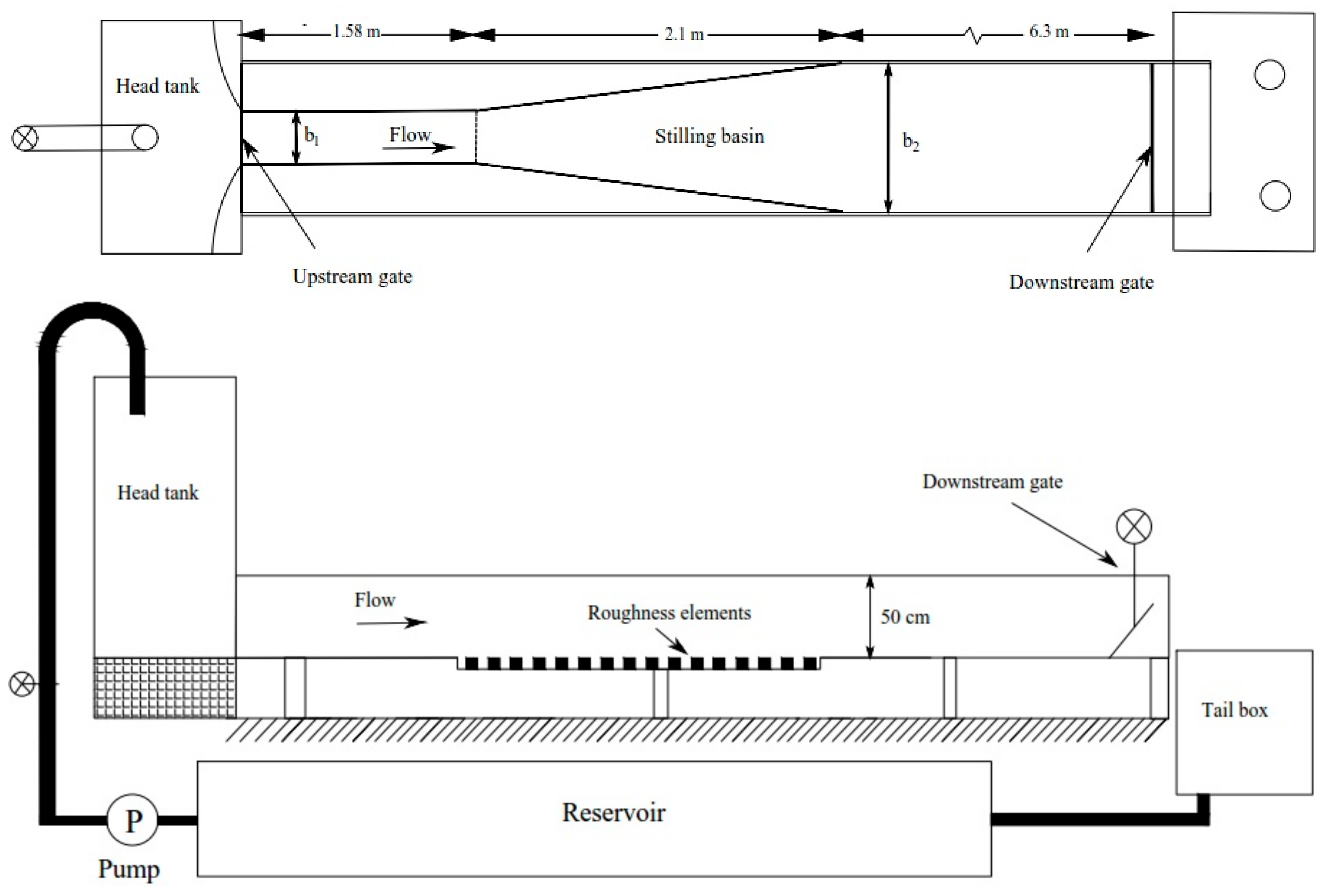
The experiments were conducted in a hydraulic laboratory of the University of Tabriz in a metal-glass horizontal rectangular flume. This facility has a relatively large-size channel 0.5 m wide, 0.5 m high and 10 m long. The sidewalls were made of glass for observational purpose. The schematic diagram of experimental arrangement is shown in Figure 2.
Water was pumped from the laboratory reservoir to the head tank of the flume by two pumps. The flow discharge was measured by an ultrasonic flow meter model Transit Time Clamp-on that located in each supply line. The inflow conditions were controlled by a vertical sluice gate with a semi-circular rounded shape (Ø = 0.2 m) and the downstream coefficient of contraction was about unity. Also, the downstream flow conditions were controlled by a vertical gate. In the first series of experiments, when the flow was established, the inflow depth of flow (y1), the sequent depth of flow (y2) and the fluctuating of free surface elevations above the hydraulic jump were measured using ultrasonic sensors Data Logic US30 with operation range of 10–100 cm and an accuracy of ±0.1 mm that were mounted above the channel. Following Hager [10], the length of the hydraulic jump (Lj) was measured between the toe of the hydraulic jump and the location where the gradually varied flow starts. The length of the hydraulic jump was measured by a fabric ruler with a reading accuracy of ±1 mm installed along the channel.
In all the experiments the upstream gate opening was fixed at h = 0.021 m and the hydraulic jump toe was set at a longitudinal position x1 = 1.58 m for all experiments. To investigate the effect of roughness, discontinuous dissipative elements of lozenge shape (the shape of roughness elements was chosen according to the study of Bejestan and Neisi [33]) with two heights (r = 0.014 m and 0.028 m) were installed on the horizontal bed (Figure 3). The crest of these elements were at the same level as the upstream bed. In this way, the dissipative elements would not be protruding into the flow [18]. Thus, the elements were not directly subjected to the incoming jet.
Four glass physical models were built with divergence ratio (B = b1/b2) of 0.4, 0.6, 0.8, and 1 (where b1 and b2 are the widths of the stilling basin in upstream and downstream of the hydraulic jump, respectively). For each set of experiments, each model was tightly installed in the flume. For each experiment, the inflow depth (y1) and the sequent depth (y2), the length of the hydraulic Jump (Lj), the roller length of the hydraulic jump (Lr) and the width of channel where the hydraulic jump ends (b) were measured. Table 2 lists the experiments carried out in the present study.
2.2. Dimensional Analysis
The sequent depth (y2) and length of the hydraulic jump (Lj), can be expressed as:
where y1 is the inflow depth, V1 is the average velocity at the beginning of the hydraulic jump, g is the gravitational acceleration, is the kinematic viscosity of water, is the density of water, r is the height of dissipative elements, b1 and b2 are the widths of stilling basin upstream and downstream of the hydraulic jump, respectively. Based on the principle of dimensional analysis, using the Pi theorem by selecting y1, V1 and as three repeated variables, the functional relationships can be expressed in dimensionless form as:
where Fr1 is the inflow Froude number at the beginning of the hydraulic jump and Re1 is the inflow Reynolds number. For large values of Re1 (as in this study), viscous effects can be neglected (Rajaratnam [17], Hager and Bremen [9]). Therefore the sequent depth ratio and relative length of the hydraulic jump are obtained as follows:
3. Results and Discussion
In this study, in order to investigate the S-jump on gradually expanding basin with roughened bed, its characteristics such as length of the hydraulic jump, sequent depth, roller length of the hydraulic jump, bed shear stress, and energy loss were evaluated. The results are discussed in the following sections.
3.1. Sequent Depth Ratio
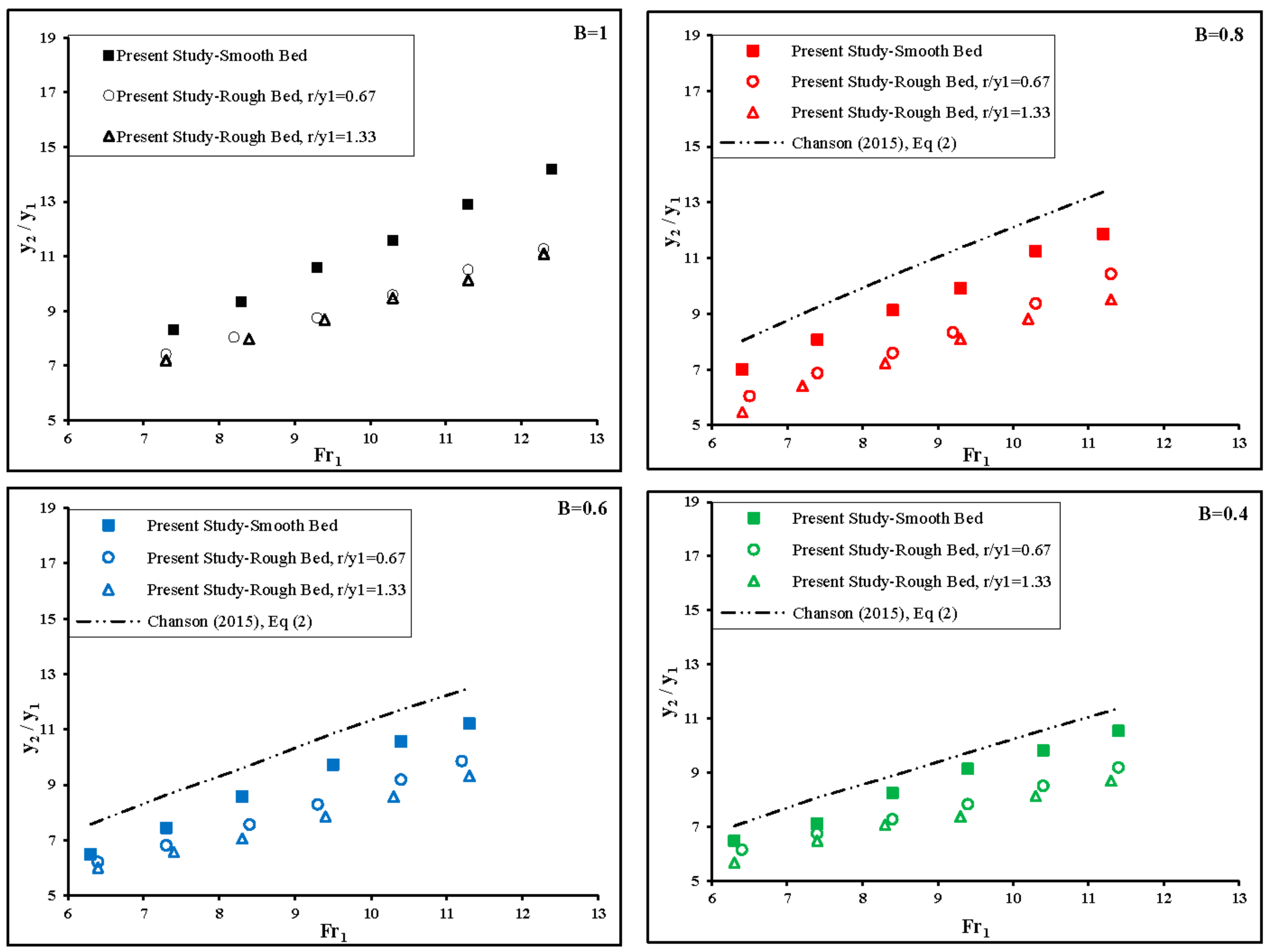
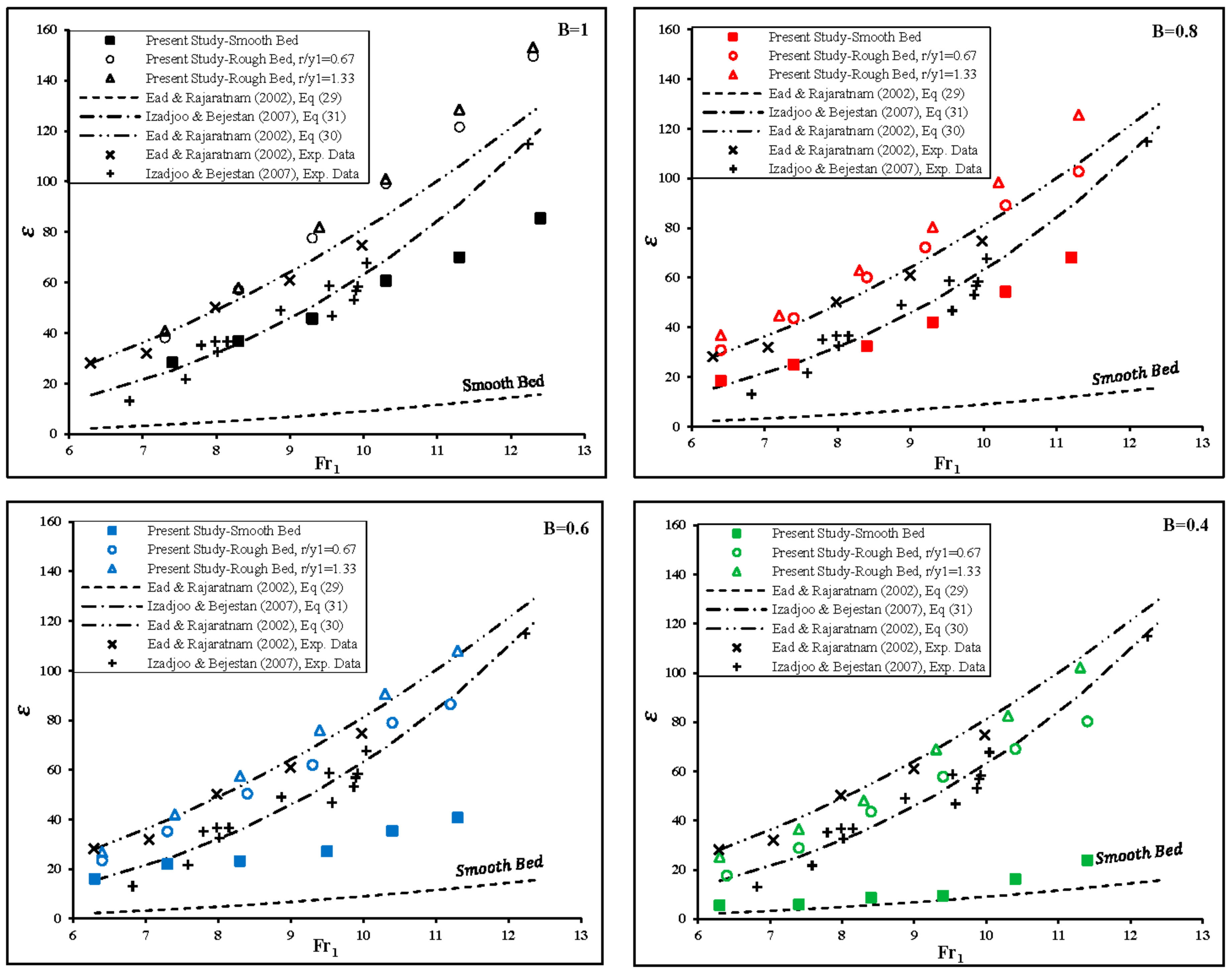
The sequent depth ratio (y2/y1), considering the Equation (10), is dependent on the inflow Froude number (Fr1), the relative height of roughness elements (r/y1) and the divergence ratio of walls (B = b1/b2). To evaluate the effect of dissipative elements on the sequent depth ratio of the hydraulic jump, in Figure 4 the values of y2/y1 are plotted versus the inflow Froude number. Also in Figure 4, the sequent depth ratios are compared with Equation (2) proposed by Chanson and Carvalho [1] for the hydraulic jump in an irregular channel.
According to Figure 4 in all divergence ratio of basin walls, the sequent depth values on the rough bed decreased as compared with the classical hydraulic jump which is directly related to the inflow Froude number. Also, the sequent depth ratio (y2/y1), decreased as the height of the roughness elements increased. Visual observations indicated that the flow separation and recirculation vortex were formed between the roughness elements. By the increasing dissipative elements height, a recirculation vortex was developed, reducing the sequent depth ratio. Also, The results showed that the sequent depth ratio for the hydraulic jump on gradually expanding channel was smaller than that of the corresponding classic hydraulic jump on a rectangular channel.
The relationship between the sequent depth ratio (y2/y1) with Fr1 and two height of the roughness elements and four divergence ratio of the channel walls could be described with the following regression-based equation with a coefficient of determination (R2) equal to 0.95.
It can be seen from Equation (12) that the sequent depth ratio increased with the increasing inflow Froude number and divergence ratio. Also, the sequent depth ratio decreased with the increasing roughness elements height.
A comparison between all the measured y2/y1 values in the present study, Ead and Rajaratnam [18] and CarolloFerro [31], and the values calculated from Equation (12) are presented in the Figure 5. The results indicated that the computed data were close to the line of agreement and there is a ±10% difference with the corresponding measured values. Also, the computed data for y2/y1 by Equation (12) shows a good agreement with previous investigations and only 6 of 190 ratios y2/y1 fall out the error band of ±10%.
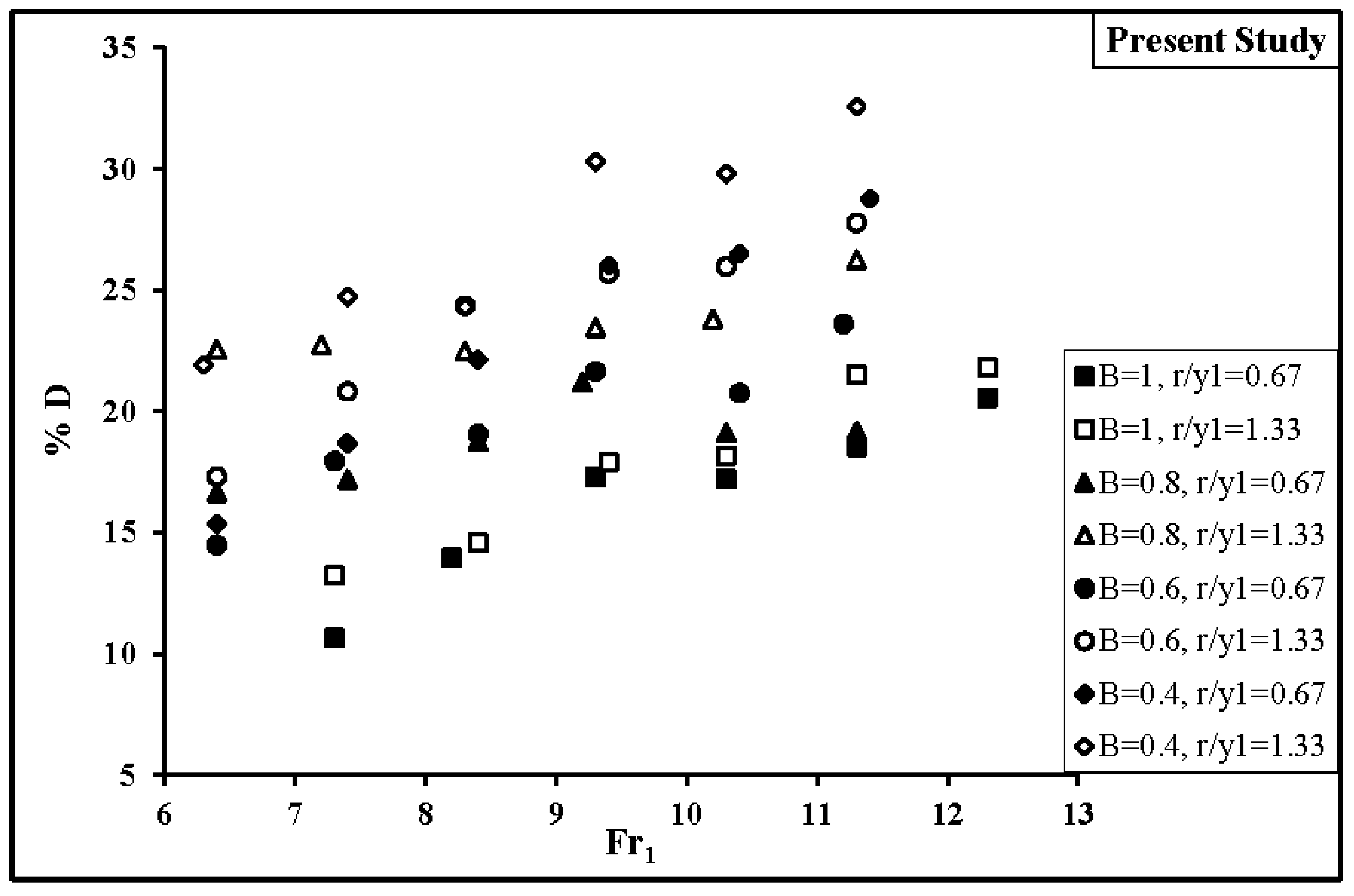
The dimensionless depth deficit parameter, D, was defined by Ead and Rajaratnam [18], as , that represents the reduction of the sequent depth. In this equation, is the sequent depth of the hydraulic jump on a smooth bed with the same upstream conditions. Figure 6 shows the variation of D versus the inflow Froude number for the experimental data. As shown in the Figure 6, the maximum reduction of sequent depth is 32.6% in the divergence ratio of B = 0.4 and the relative height of r/y1 = 1.33.
The average reduction of the sequent depth (D%) for each experiment is shown in Table 3. It was found from the present study that the sequent depth ratios in the gradually diverging stilling basin are less than those of the classic hydraulic jump and on the smooth bed, respectively.
3.2. Relative Roller Length of the Hydraulic Jump
The length of the hydraulic jump because of the surface waves is hard to define [35]. Many experimental studies (Pietrkowski (1932), Smetana (1937) and Hager et al. [36]) suggested that the roller length (Lr) was actually a better length characteristic than the hydraulic jump length because it was easy to observe and was properly defined for steady flow conditions [35]. The roller length (Lr), is the horizontal distance between the toe section with the flow depth y1 and the roller end. For the hydraulic jump in smooth and rough horizontal channels, using the available experimental data CarolloFerro [31] proposed the following equation for the roller length of the hydraulic jump:
where the coefficient a depends on experimental conditions.
Carollo and Ferro (2004) by using the roller length data for the smooth and rough beds by HagerBremen [36], Hughes and Flack [19] and Ead and Rajaratnam [18], proposed the following equations for the roller length [31]:
where a0 and b0 are numerical coefficients depending on bed roughness. In this investigation, the experimental data of the roller length were used to test the applicability of Equations (13)–(15).
Figure 7 shows that a single relationship between the pairs of (Lr/y1, y1/y2) and (Lr/y1, y2/y1 − 1) can be obtained independent of the roughness height and divergence ratio but according to Figure 8, a single relationship cannot be established using the pairs (Lr/y1, Fr1 − 1), as it was shown by CarolloFerro [31].
For each divergence ratio (B = 1, 0.8, 0.6 and 0.4) and each roughness height (r = 1.4 and 2.8 cm) the calculated of coefficients a, a0 and b0 are listed in Table 4. The estimates of a, a0 and b0 obtained by Carollo and Ferro (2004) using the measurements of Hughes and Flack [19] and HagerBremen [36] and also the estimates of a, a0 and b0 obtained by CarolloFerro [31] are listed in Table 4.
According to the Figure 7 and Figure 8, and values listed in Table 4, b0 depends on the roughness height and divergence ratio whereas a and a0 can be assumed constant. Using experimental data from this study and fitting Equations (13) and (14) to them, gives a = 4.745 and a0 = 2.309. So Equations (13) and (14) can be written as it follows:
where the coefficient of determination (R2) was equal to 0.84. This equation shows that the relative roller length linearly increased with the increasing ratio of (y2/y1 − 1).
where the coefficient of determination (R2) was equal to 0.86. This equation shows that the relative roller length exponentially decreased with the increasing ratio of (y1/y2).
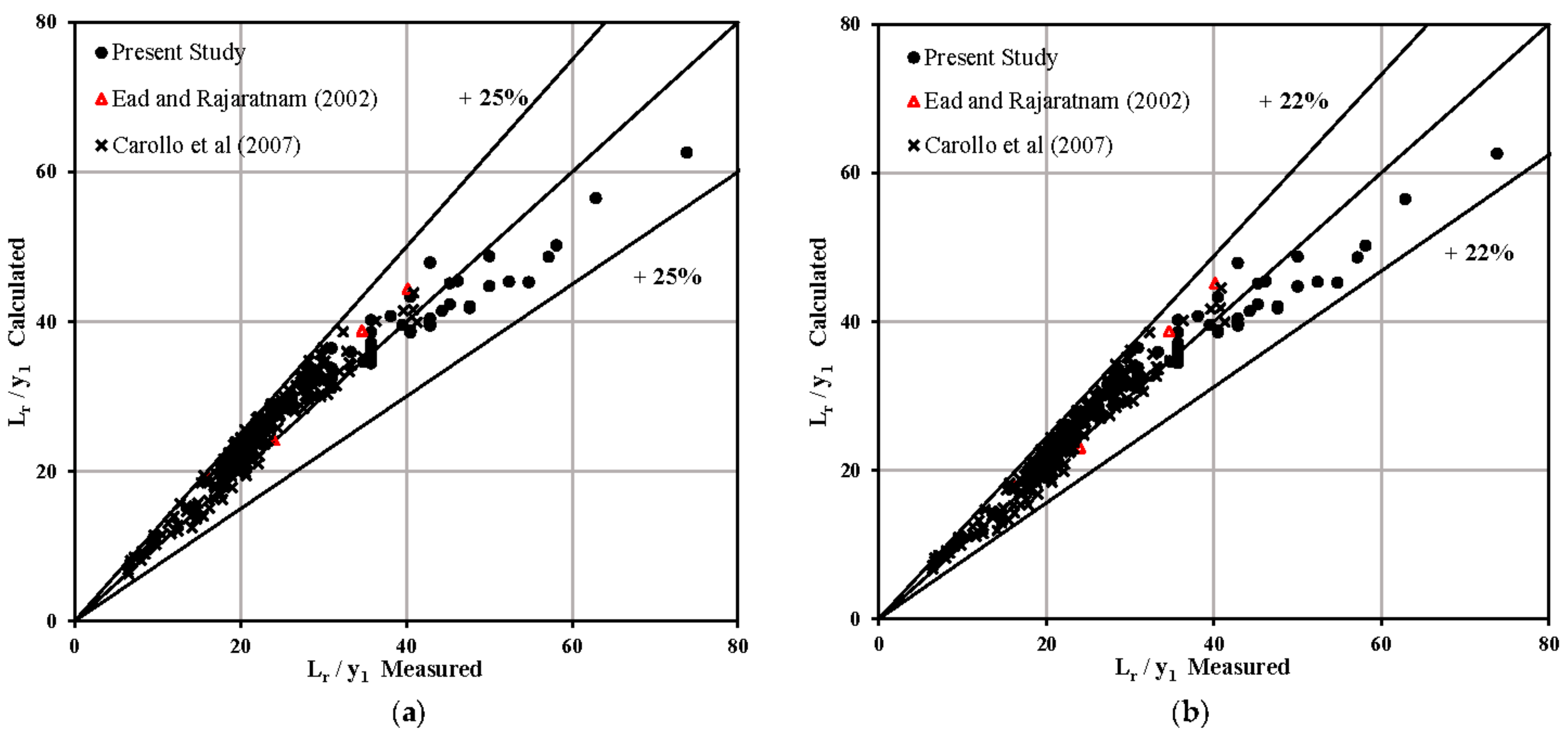
A comparison between the measured values of the ratio Lr/y1 in the present study, Ead and Rajaratnam [18] and CarolloFerro [31] and the values from Equations (16) and (17) are plotted in the Figure 9. As shown in Figure 9, the computed data by Equations (16) and (17) showed a ±25% and ±22% difference with the corresponding measured values, respectively. Also, the computed ratios of Lr/y1 by Equations (16) and (17) for the experimental data of Ead and Rajaratnam [18] and CarolloFerro [31] are in the range of ±25%.
According to estimates values of b0, the divergence ratio, and the relative roughness, the relationship between them, could be described by the following regression-based equation with a coefficient of determination (R2) equal to 0.89.
So by inserting Equation (18) into Equation (15), the following equation was obtained:
The comparison between the measured values of the ratio Lr/y1 in the present study, Ead and Rajaratnam [18] and CarolloFerro [31] and those calculated using the Equation (19) are plotted in Figure 10. According to this Figure, the computed data by the Equation (19) showed a ±26% difference with the corresponding measured values.
3.3. Relative Length of the Hydraulic Jump
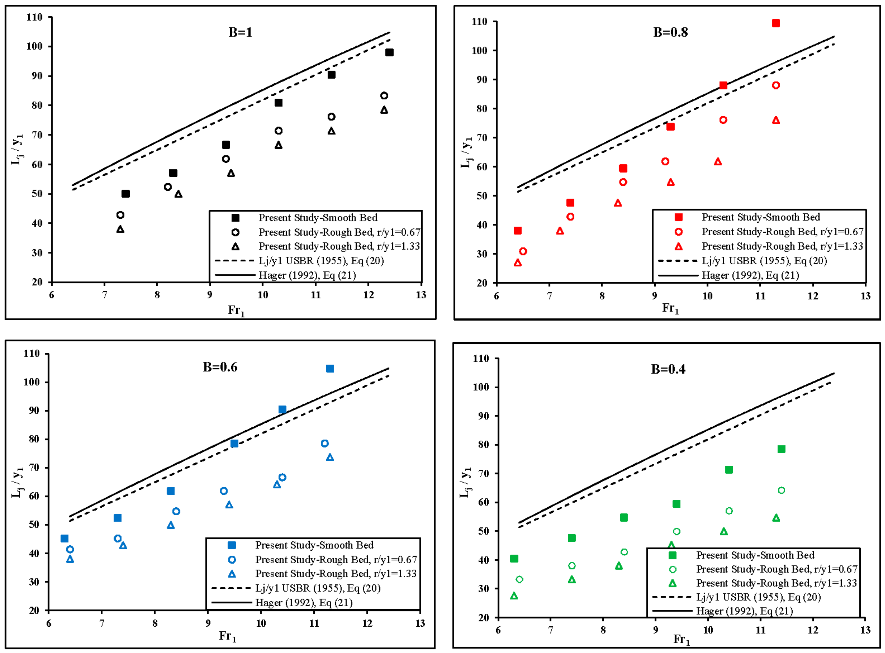
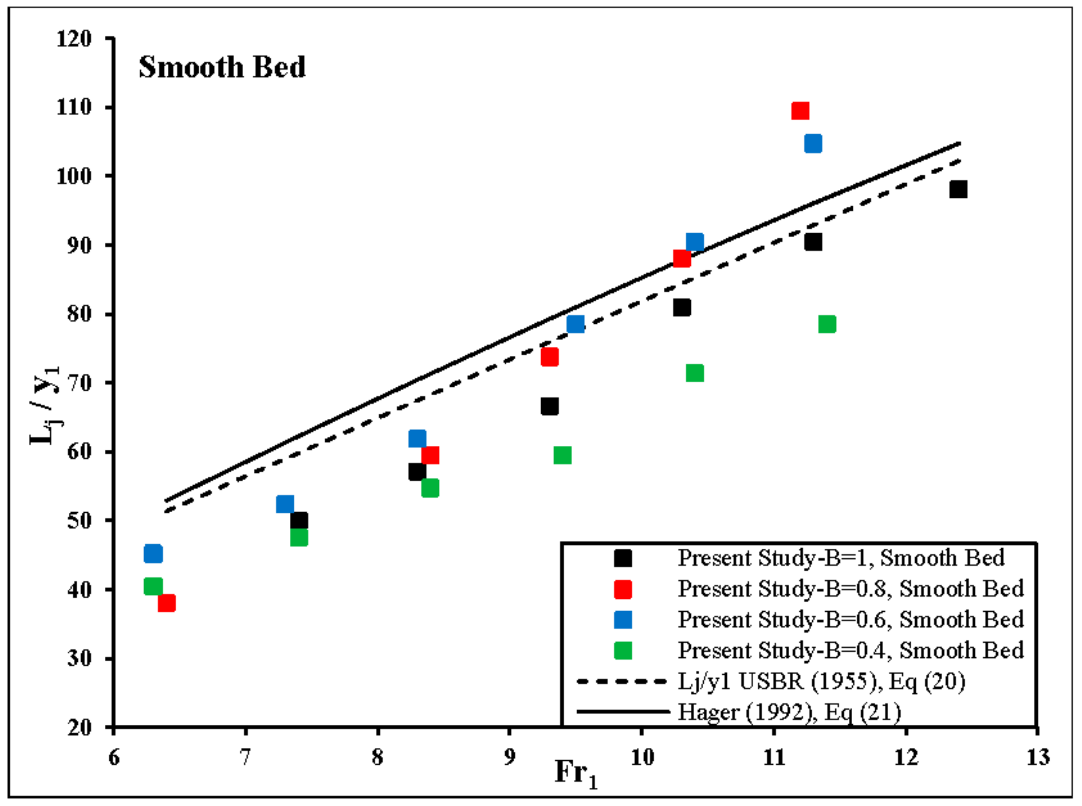
The main role of the roughness elements in an expanding stilling basin may be considered to be the stabilization of the hydraulic jump and the improvement of its conditions to prevent the hydraulic jump runoff towards the downstream area. The values of the relative length of the hydraulic jump (Lj/y1) for different divergence ratio, are plotted versus the inflow Froude number in Figure 11. The results showed that the roughness element caused a significant reduction of the hydraulic jump length. Also, Figure 11 showed that the roughness with height 0.028 m was more effective than the other height of dissipative elements to reduce the relative length of the hydraulic jump (Lj/y1). In these Figure, the relative lengths of a classical hydraulic jump based on the following equations proposed by USBR [37] and Hager [10], respectively, were also compared.
In addition, the values of the relative length of the hydraulic jump (Lj/y1) obtained in the present study with those obtained by Hager [10] and USBR [37] are compared in Figure 12 and Figure 13.
As can be seen from Figure 12 and Figure 13, the length of the hydraulic jump increased by the increasing inflow Froude number. According experimental observation in divergence ratio of B = 0.8 and B = 0.6 because of turbulence and instability of the flow in an expanding channel, the hydraulic jump transmitted to the downstream of channel. Thus, the length of the hydraulic jump was greater than those on divergence ratio of B = 1 and B = 0.4. Experimental observations showed that, installing roughness elements stabilized the jump on the channel.
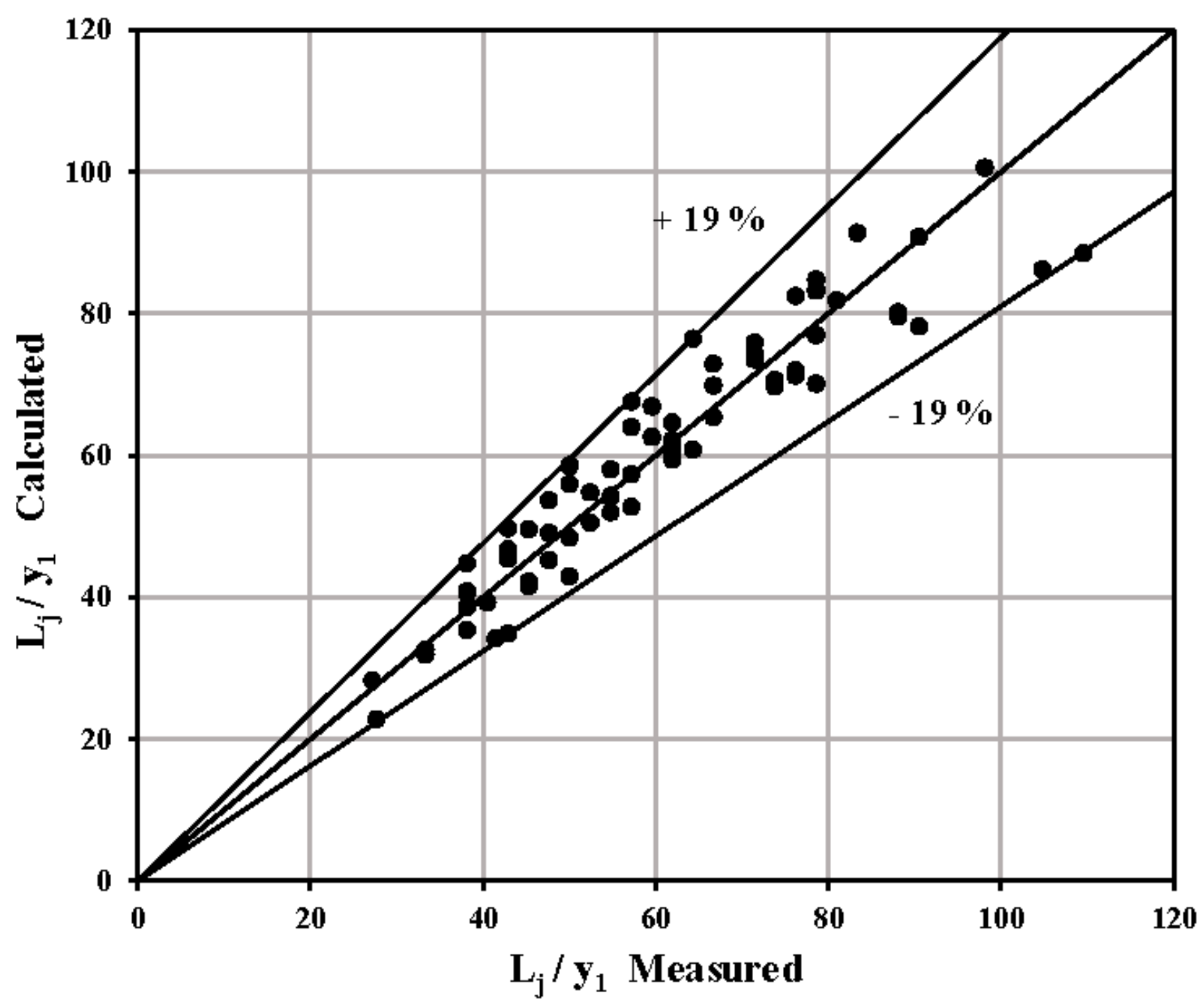
The regression-based relationship between the relative length of the hydraulic jump (Lj/y1), the inflow Froude number (Fr1), divergence ratio (B) and the relative height of roughness (r/y1) can be described by the Equation (22) with a coefficient of determination (R2) equal to 0.89. Then the values of relative length ratio for all the experiments were computed using the Equation (22) and compared with corresponding measured values in Figure 14. It was obtained from the Figure 14 that the result produced by the proposed relationship showed ±19% difference with the corresponding measured values.
According to the Equation (23), the relative length of the hydraulic jump increased with the increasing inflow Froude number and divergence ratio, also the relative length of the hydraulic jump decreased with the increasing roughness elements ratio.
3.4. Energy Dissipation
The loss of energy in the hydraulic jump (EL) is equal to the difference between the specific energy upstream and downstream of the hydraulic jump, and it can be defined as below:
where E1 and E2 are the energy height at the toe and the end of the hydraulic jump, respectively. The energy loss in the diverging hydraulic jump was calculated from the specific energy and continuity equation as it follows:
where EL and EL/E1 are the energy loss and the relative loss of energy, respectively. The measured relative energy losses (EL/E1) due to the hydraulic jump were calculated for different divergence ratio with two heights of bed roughness elements and the relative energy loss values were plotted versus the inflow Froude number in Figure 15.
It can be seen from these Figures that for the hydraulic jump in all expanding channels that (EL/E1) values corresponding to rough beds are greater than those for the smooth bed. This difference increases with the increasing inflow Froude number (Fr1). The trend of the measured values for each model in these Figures shows that for the same inflow Froude number the relative energy loss increases with the increasing height of roughness elements. Also, Figure 15 shows that for the hydraulic jump in all expanding stilling basin, the relative energy loss is greater than those for the rectangular section.
In the Figure 16 the relative energy loss of the hydraulic jump (EL/E1) for different divergence ratios were compared with each other. The Figures indicated that the relative energy loss increased with the decreasing divergence ratio and the channel with divergence ratio of B = 0.4 is more effective to dissipate the energy of the hydraulic jump. This is probably due to the existence of lateral force and high turbulence and rolling flow along the longitudinal section.
The relationship between the relative loss of energy (EL/E1), the inflow Froude number (Fr1), the relative height of roughness (r/y1) and the divergence ratio of channel walls (B) the following equation was obtained by non-linear regression as:
where the coefficient of determination (R2) was equal to 0.98.
As it can be seen from Equation (26), the relative loss of energy increased with the increasing logarithmic of the inflow Froude number and increasing the relative roughness ratio. Also, the relative loss of energy decreased with the increasing divergence ratio.
3.5. Bed Shear Stresses
The shear force coefficient introduced by Rajaratnam [6], was defined as [18]:
where is the specific weight of water. The bed shear force coefficient for the hydraulic jump on the smooth and rough beds was calculated by the following equations, respectively [18]:
The value of index was determined for all experiments by using Equation (27) and it was plotted versus the inflow Froude number (Fr1) in Figure 17.
To investigate the effect of the divergence ratio of channel walls on the bed shear coefficient, the results of this study were compared with Equations (28) and (29) and the following equation by Izadjoo and Shafai Bejestan [32] for the hydraulic jump on the rectangular channel with the rough bed. Also, the results of present experimental data are compared in Figure 17 with those from the studies of Ead and Rajaratnam [18] and Izadjoo and Shafai Bejestan [32].
Figure 17 shows that the bed shear coefficient increases with the increasing of the inflow Froude number for all experiments. As it can be seen from Figure 17, the amount of in the hydraulic jump over rough beds in all divergence ratio was increased as compared with the smooth bed. The roughness elements with the height of 0.028 m are more effective in increasing the bed shear coefficient. The average value of the bed shear coefficient on the rough bed for different divergence ratios B (1, 0.8, 0.6 and 0.4) for two heights of roughness elements are 10.3, 11.1, 9.5 and 8.3 respectively. It can be mentioned that there was a good agreement between the results of this study and the results obtained by Ead and Rajaratnam [18], and Izadjoo and Shafai Bejestan [32].
4. Conclusions
To reduce the construction costs of stilling basin, a change in the plan and profile sections of the basins can be useful. In this paper, the main features of a hydraulic jump under both the effect of the height of bed roughness and expansion of basin walls condition were investigated. Experimental observations showed that at high inflow Froude numbers the hydraulic jump on an expanding channel is unstable which causes some difficulties in controlling of the hydraulic jump. Also, the location of the hydraulic jump toe oscillated over the time of ±0.1 m about its average longitudinal position. It should be noted that, installing roughness elements stabilized the hydraulic jump on the channel. Equations (12), (22) and (26) were proposed for estimating the sequent depth ratio (y2/y1), the relative length of the hydraulic jump (Lj/y1) and the relative loss of energy (EL/E1), respectively. The Equation (12) shows that the sequent depth ratio increased with the increasing inflow Froude number and the divergence ratio. Also, the sequent depth ratio decreased as the roughness elements ratio increased. The relative length of the hydraulic jump for a given inflow Froude number, decreased as the roughness elements ratio increased. A comparing between the measured values of EL/E1 and those calculated by Equation (26) showed that, Equation (26) allows an estimation for calculating the relative energy loss in expanding basin with roughened bed. Also, three Equations (16), (17) and (19) for calculating the roller length of the hydraulic jump were developed. The roller length ratio decreased by the increasing roughness elements ratio and increased as the divergence ratio increased.
The application of Equations (13)–(15) showed that the coefficients a and a0 can be considered constant whereas the coefficient b0 is related to divergence ratio and relative roughness height. In conclusion, this paper investigated the effects of the height of roughness elements and divergence ratio of walls on the main characteristics of the hydraulic jump. Table 5 lists the equations derived in this study.
Acknowledgments
The authors would like to thank vice-chancellor for research of University of Tabriz (IRAN) for providing financial support. The first author acknowledges that the time spent at the University of Napoli Federico II was partially supported by the Ministry of Science, Research, and Technology of IRAN. The writers are thankful to Milad Abdollahpour for building the experimental arrangement. All sources of funding of the study should be disclosed. Please clearly indicate grants that you have received in support of your research work. Clearly state if you received funds for covering the costs to publish in open access.
Author Contributions
Nasrin Hassanpour, Ali Hosseinzadeh Dalir and Davod Farsadizadeh designed and supervised the experiments. Nasrin Hassanpour, Ali Hosseinzadeh Dalir and Carlo Gualtieri conducted the analysis on the experimental data. Nasrin Hassanpour wrote the paper. Carlo Gualtieri, Ali Hosseinzadeh Dalir and Davod Farsadizadeh edited the manuscript. All authors read and approved the final manuscript.
Conflicts of Interest
The authors declare no conflict of interest.
Notation
The following symbols are used in this paper:
| a | The coefficient of Equation (13) |
| a0 | The coefficient of Equation (14) |
| B | Divergence ratio |
| b0 | The coefficient of Equation (15) |
| b1 | Width of the stilling basin in upstream |
| b2 | Width of the stilling basin in downstream |
| d1 | Inflow depth of the hydraulic jump |
| d2 | Flow depth in downstream of the hydraulic jump |
| E1 | Specific energy upstream the hydraulic jump |
| E2 | Specific energy downstream the hydraulic jump |
| EL | Energy loss in the hydraulic jump |
| Fr1 | Inflow Froude number, where |
| g | Gravitational acceleration |
| Re1 | Inflow Reynolds number |
| r | Height of roughness elements |
| Lj | Length of the hydraulic jump |
| Lr | Roller length of the hydraulic jump |
| Lj/y1 | Relative length of the hydraulic jump |
| Lr/y1 | Relative roller length of the hydraulic jump |
| q | Discharge per unit width |
| EL/E1 | Relative energy loss |
| y1 | Inflow depth of the hydraulic jump |
| y2 | Sequent depth of the hydraulic jump |
| y2* | Sequent depth of the classic hydraulic jump |
| M1 | Momentum flux at the beginning of the hydraulic jump |
| M2 | Momentum flux at the end of the hydraulic jump |
| P1 | Hydrostatic force at the section upstream of the hydraulic jump |
| P2 | Hydrostatic force at the section downstream of the hydraulic jump |
| R2 | Coefficient of determination |
| Fp1 | Pressure force upstream the hydraulic jump |
| Fp2 | Pressure force downstream the hydraulic jump |
| Fe | Pressure force on the expanding wall |
| Integrated bed shear stress over the hydraulic jump length | |
| Shear force coefficient | |
| Mass density of water | |
| Kinematic viscosity of water |
References
- Chanson, H.; Carvalho, R.F. Hydraulic jumps and stilling basins. In Energy Dissipation in Hydraulic Structures; CRC Press: Leiden, The Netherlands, 2015; p. 168. [Google Scholar]
- Chanson, H. Development of the Bélanger equation and backwater equation by Jean-Baptiste Bélanger (1828). J. Hydraul. Eng. 2009, 135, 159–163. [Google Scholar] [CrossRef]
- Carollo, F.G.; Ferro, V.; Pampalone, V. New solution of classical hydraulic jump. J. Hydraul. Eng. 2009, 135, 527–531. [Google Scholar] [CrossRef]
- Gill, M. Effect of boundary roughness on hydraulic jump. Water Power Dam Constr. 1980, 32, 22–24. [Google Scholar]
- Peterka, A.J. Hydraulic Design of Stilling Basins and Energy Dissipators; United States Department of the Interior: Washington, DC, USA, 1958.
- Rajaratnam, N. The Hydraulic Jump as a Well Jet. J. Hydraul. Div. 1965, 91, 107–132. [Google Scholar]
- Leutheusser, H.J.; Kartha, V.C. Effects of inflow conditions on hydraulic jump. J. Hydraul. Div. 1972, 98, 1367–1385. [Google Scholar]
- McCorquodale, J.A.; Khalifa, A. Internal flow in hydraulic jumps. J. Hydraul. Eng. 1983, 109, 684–701. [Google Scholar] [CrossRef]
- Hager, W.H.; Bremen, R. Classical hydraulic jump: Sequent depths. J. Hydraul. Res. 1989, 27, 565–585. [Google Scholar] [CrossRef]
- Hager, W.H. Energy Dissipators and Hydraulic Jump; Springer Science and Business Media: Berlin, Germany, 1992; Volume 8. [Google Scholar]
- Wu, S.; Rajaratnam, N. Free jumps, submerged jumps and wall jets. J. Hydraul. Res. 1995, 33, 197–212. [Google Scholar] [CrossRef]
- Mossa, M.; Tolve, U. Flow visualization in bubbly two-phase hydraulic jump. Trans.-Am. Soc. Mech. Eng. J. Fluids Eng. 1998, 120, 160–165. [Google Scholar] [CrossRef]
- Gualtieri, C.; Chanson, H. Experimental analysis of Froude number effect on air entrainment in the hydraulic jump. Environ. Fluid Mech. 2007, 7, 217–238. [Google Scholar] [CrossRef] [Green Version]
- Chanson, H.; Gualtieri, C. Similitude and scale effects of air entrainment in hydraulic jumps. J. Hydraul. Res. 2008, 46, 35–44. [Google Scholar] [CrossRef]
- Gualtieri, C.; Chanson, H. Effect of Froude number on bubble clustering in a hydraulic jump. J. Hydraul. Res. 2010, 48, 504–508. [Google Scholar] [CrossRef] [Green Version]
- Gualtieri, C.; Chanson, H. Interparticle arrival time analysis of bubble distributions in a dropshaft and hydraulic jump. J. Hydraul. Res. 2013, 51, 253–264. [Google Scholar] [CrossRef]
- Rajaratnam, N. Hydraulic jumps on rough beds. Trans. Eng. Inst. Can. 1968, 11, 1–8. [Google Scholar]
- Ead, S.; Rajaratnam, N. Hydraulic jumps on corrugated beds. J. Hydraul. Eng. 2002, 128, 656–663. [Google Scholar] [CrossRef]
- Hughes, W.C.; Flack, J.E. Hydraulic jump properties over a rough bed. J. Hydraul. Eng. 1984, 110, 1755–1771. [Google Scholar] [CrossRef]
- Mossa, M.; Petrillo, A.; Chanson, H. Tailwater level effects on flow conditions at an abrupt drop. J. Hydraul. Res. 2003, 41, 39–51. [Google Scholar] [CrossRef] [Green Version]
- Pagliara, S.; Lotti, I.; Palermo, M. Hydraulic jump on rough bed of stream rehabilitation structures. J. Hydro-Environ. Res. 2008, 2, 29–38. [Google Scholar] [CrossRef]
- Mossa, M. On the oscillating characteristics of hydraulic jumps. J. Hydraul. Res. 1999, 37, 541–558. [Google Scholar] [CrossRef]
- Wanoschek, R.; Hager, W.H. Hydraulic jump in trapezoidal channel. J. Hydraul. Res. 1989, 27, 429–446. [Google Scholar] [CrossRef]
- Hager, W. Hydraulic jump in non-prismatic rectangular channels. J. Hydraul. Res. 1985, 23, 21–35. [Google Scholar] [CrossRef]
- Lawson, J.D.; Phillips, B.C. Circular hydraulic jump. J. Hydraul. Eng. 1983, 109, 505–518. [Google Scholar] [CrossRef]
- Arbhabhirama, A.; Abella, A.U. Hydraulic jump within gradually expanding channel. J. Hydraul. Div. 1971, 97, 31–42. [Google Scholar]
- Diskin, M. Hydraulic jump in trapezoidal channels. Water Power 1961, 13, 12–17. [Google Scholar]
- Omid, M.; Esmaeeli Varaki, M.; Narayanan, R. Gradually expanding hydraulic jump in a trapezoidal channel. J. Hydraul. Res. 2007, 45, 512–518. [Google Scholar] [CrossRef] [Green Version]
- Herbrand, K. The spatial hydraulic jump. J. Hydraul. Res. 1973, 11, 205–218. [Google Scholar] [CrossRef]
- Agarwal, V. Graphical solution to the problem of sequent depth and energy loss in spatial hydraulic jump. In Proceedings of the Institution of Civil Engineers-Water and Maritime Engineering; Thomas Telford Ltd.: London, UK, 2001. [Google Scholar]
- Carollo, F.G.; Ferro, V.; Pampalone, V. Hydraulic jumps on rough beds. J. Hydraul. Eng. 2007, 133, 989–999. [Google Scholar] [CrossRef]
- Izadjoo, F.; Shafai Bejestan, M. Corrugated bed hydraulic jump stilling basin. Appl. Sci. 2007, 7, 1164–1169. [Google Scholar]
- Bejestan, M.S.; Neisi, K. A new roughened bed hydraulic jump stilling basin. Asian J. Appl. Sci. 2009, 2, 436–445. [Google Scholar] [CrossRef]
- Wang, H.; Chanson, H. Turbulent fluctuations in hydraulic jumps: A physical study. In Proceeding of the 5th International Symposium on Hydraulic Structures: Hydraulic Structures and Society-Engineering Challenges and Extremes, Brisbane, Australia, 25–27 June 2014. [Google Scholar]
- Carollo, F.G.; Ferro, V.; Pampalone, V. New Expression of the Hydraulic Jump Roller Length. J. Hydraul. Eng. 2012, 138, 995–999. [Google Scholar] [CrossRef]
- Hager, W.H.; Bremen, R.; Kawagoshi, N. Classical hydraulic jump: Length of roller. J. Hydraul. Res. 1990, 28, 591–608. [Google Scholar] [CrossRef]
- USBR. Research Studies on Stilling Basins, Energy Dissipators and Associated Appurtenances; Hydraulic Laboratory Report (USBR- United States); USBR: Washington, DC, USA, 1955; Volume 399, pp. 393–438.
Figure 1.
Basic sketch of momentum equation for the hydraulic jump on rough bed of channel with expanding walls.
Figure 1.
Basic sketch of momentum equation for the hydraulic jump on rough bed of channel with expanding walls.

Figure 2.
Plan and side view of the experimental set-up.

Figure 3.
Definition sketch for dissipative elements with lozenge shape with divergence ratio of B = 0.4. (a) Height of roughness (r) = 1.4 cm. (b) Height of roughness (r) = 2.8 cm.
Figure 3.
Definition sketch for dissipative elements with lozenge shape with divergence ratio of B = 0.4. (a) Height of roughness (r) = 1.4 cm. (b) Height of roughness (r) = 2.8 cm.

Figure 4.
Variation of the sequent depth ratio vs. the inflow Froude number for two relative height of roughness elements (r/y1 = 0.67 and r/y1 = 1.33) and different divergence ratio (B = 1, 0.8, 0.6, 0.4).
Figure 4.
Variation of the sequent depth ratio vs. the inflow Froude number for two relative height of roughness elements (r/y1 = 0.67 and r/y1 = 1.33) and different divergence ratio (B = 1, 0.8, 0.6, 0.4).

Figure 5.
Comparison between all the y2/y1 values measured and those calculated by Equation (12).
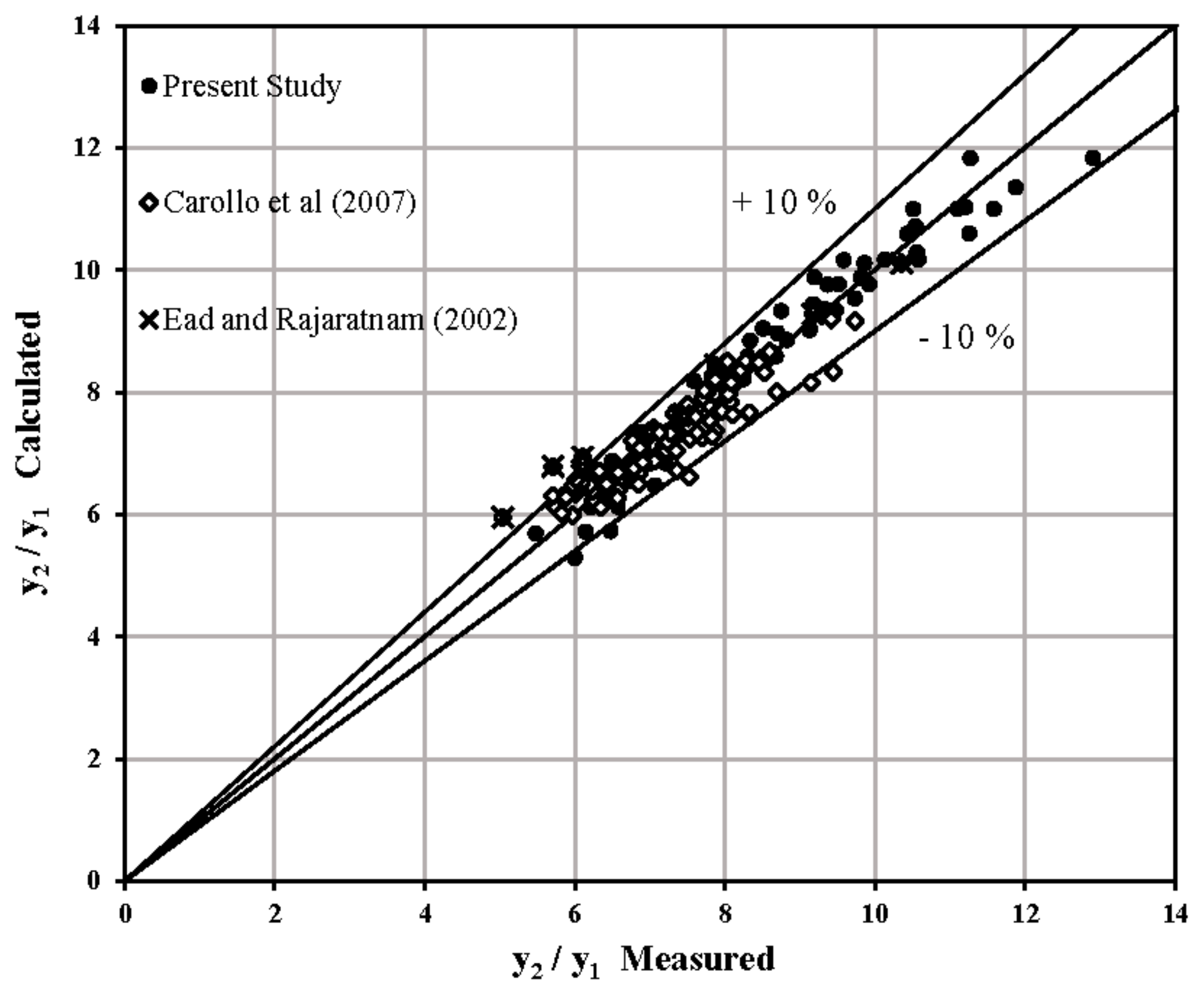
Figure 6.
Dimensionless depth deficit parameter D vs. the inflow Froude number.

Figure 7.
Relationship between the ratio of Lr/y1 and (a) the ratio of (y1/y2), (b) the difference ((y2/y1) − 1) for all experimental data.
Figure 7.
Relationship between the ratio of Lr/y1 and (a) the ratio of (y1/y2), (b) the difference ((y2/y1) − 1) for all experimental data.
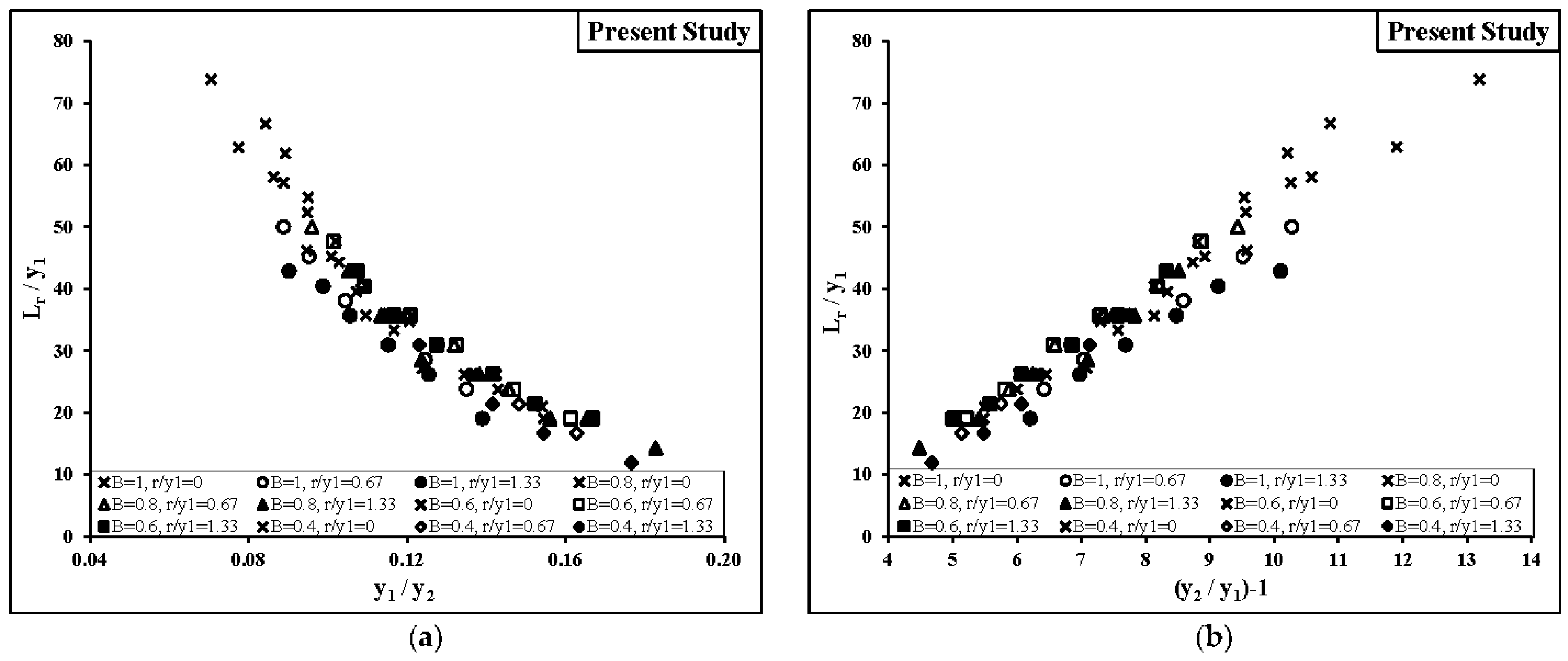
Figure 8.
Relationship between the ratio of Lr/y1 and (Fr1 − 1) for all experimental data.
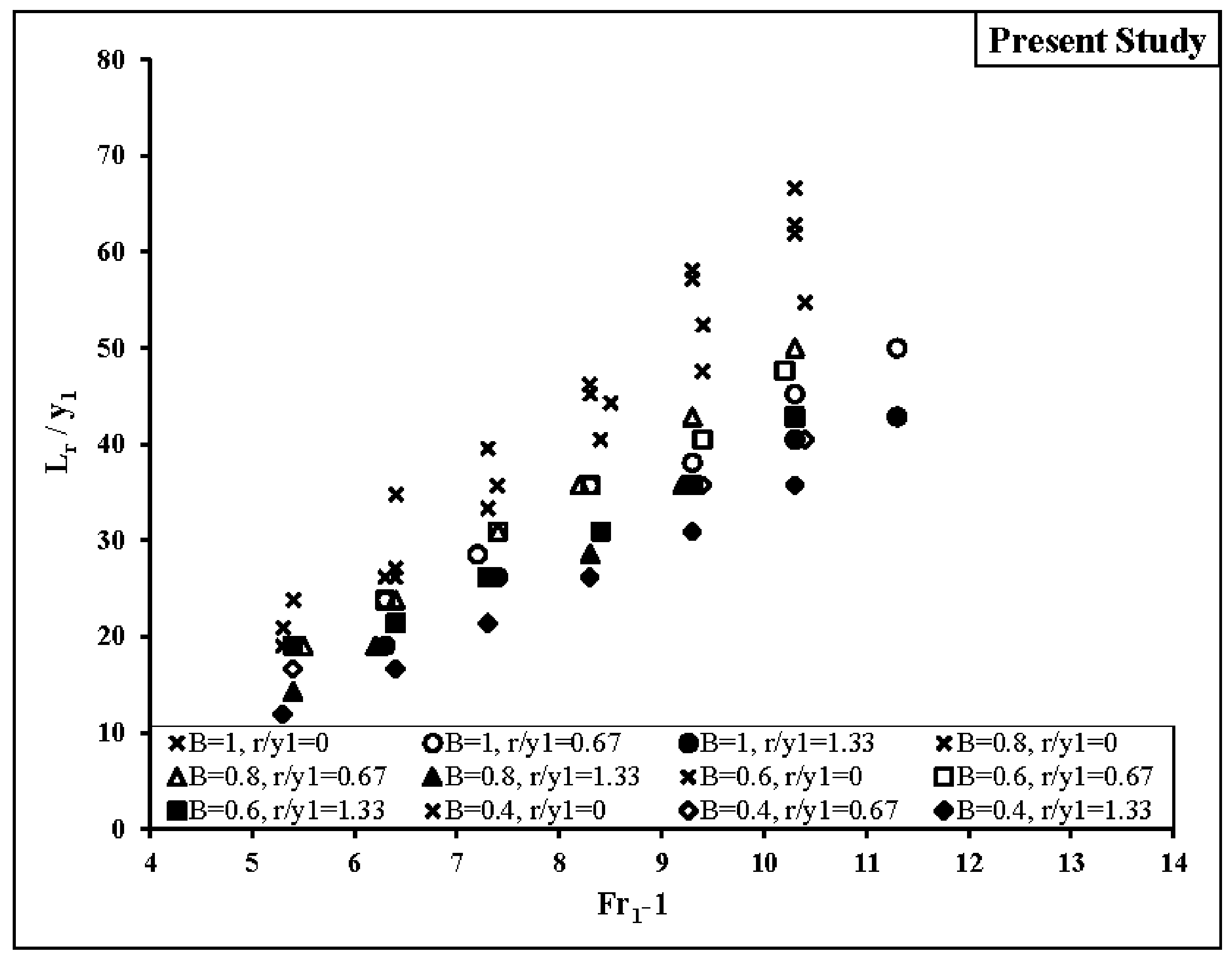
Figure 9.
Comparison between the measured values of the ratio Lr/y1 and (a) results from Equation (16), (b) results from Equation (17).
Figure 9.
Comparison between the measured values of the ratio Lr/y1 and (a) results from Equation (16), (b) results from Equation (17).

Figure 10.
Comparison between the measured values of the ratio Lr/y1 and those calculated by Equation (19).
Figure 10.
Comparison between the measured values of the ratio Lr/y1 and those calculated by Equation (19).
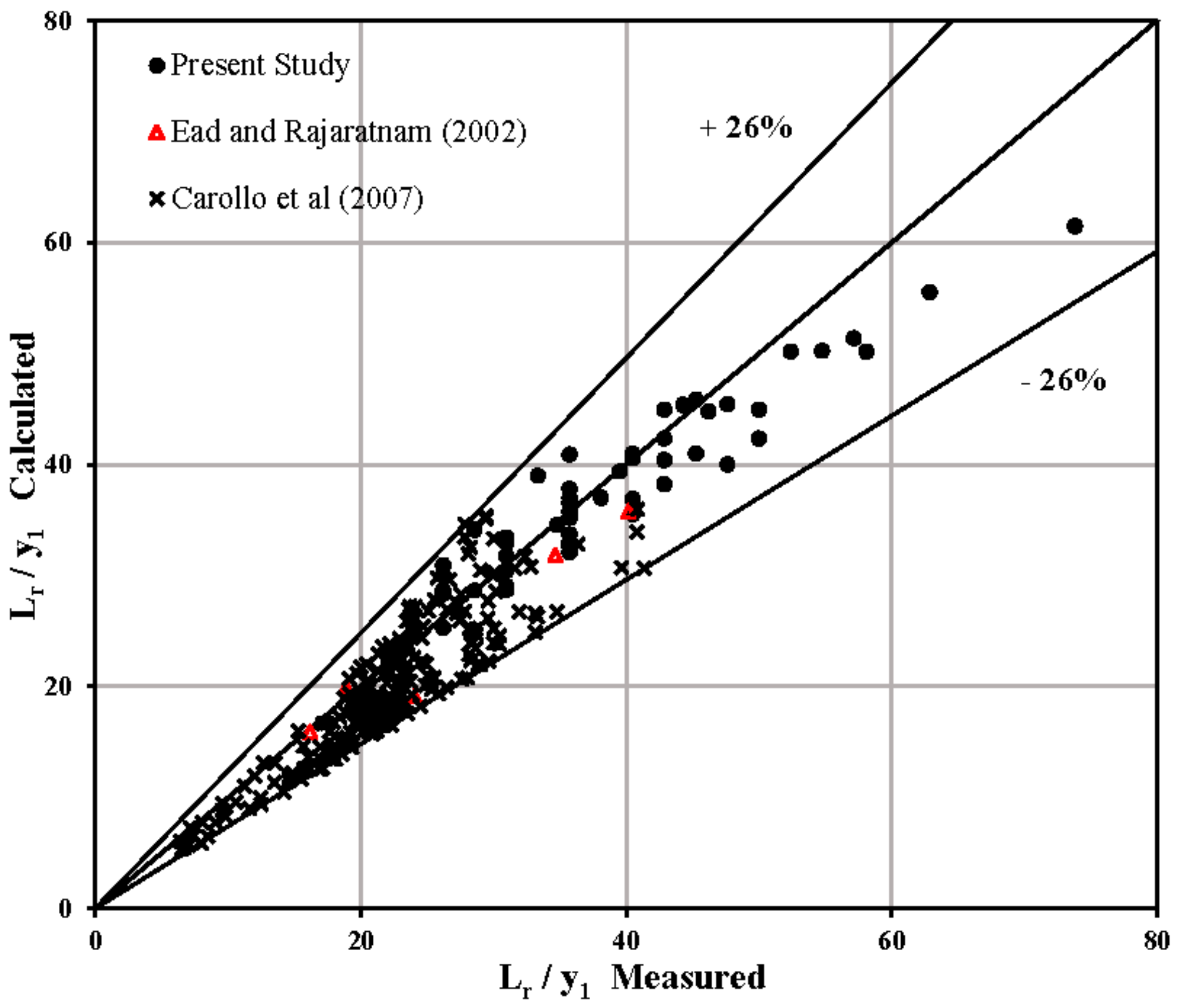
Figure 11.
Variation of the relative length of the hydraulic jump (Lj/y1) vs. the inflow Froude number for different divergence ratio (B = 1, 0.8, 0.6 and 0.4) and two relative height of dissipative elements (r/y1 = 0.67 and 1.33).
Figure 11.
Variation of the relative length of the hydraulic jump (Lj/y1) vs. the inflow Froude number for different divergence ratio (B = 1, 0.8, 0.6 and 0.4) and two relative height of dissipative elements (r/y1 = 0.67 and 1.33).

Figure 12.
Variation of the relative length of the hydraulic jump (Lj/y1) vs. the inflow Froude number with different divergence ratio on a smooth bed.
Figure 12.
Variation of the relative length of the hydraulic jump (Lj/y1) vs. the inflow Froude number with different divergence ratio on a smooth bed.

Figure 13.
Variation of the relative length of the hydraulic jump (Lj/y1) vs. the inflow Froude number with different divergence ratio on a rough bed.
Figure 13.
Variation of the relative length of the hydraulic jump (Lj/y1) vs. the inflow Froude number with different divergence ratio on a rough bed.
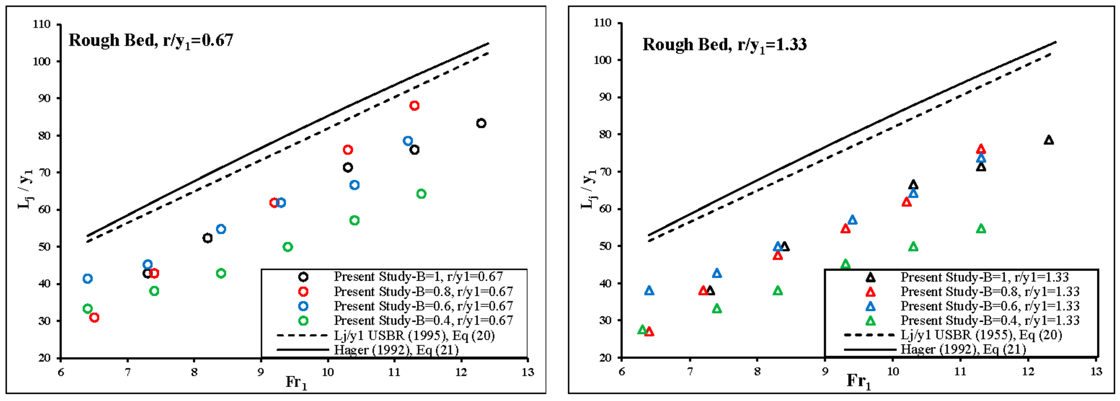
Figure 14.
Comparison between the Lj/y1 values measured in this investigation and those calculated by Equation (22).
Figure 14.
Comparison between the Lj/y1 values measured in this investigation and those calculated by Equation (22).

Figure 15.
Variation of the relative energy loss () vs. the inflow Froude number for different divergence ratio (B = 1, 0.8, 0.6 and 0.4) and two relative heights of dissipative elements (r/y1 = 0.67 and 1.33).
Figure 15.
Variation of the relative energy loss () vs. the inflow Froude number for different divergence ratio (B = 1, 0.8, 0.6 and 0.4) and two relative heights of dissipative elements (r/y1 = 0.67 and 1.33).
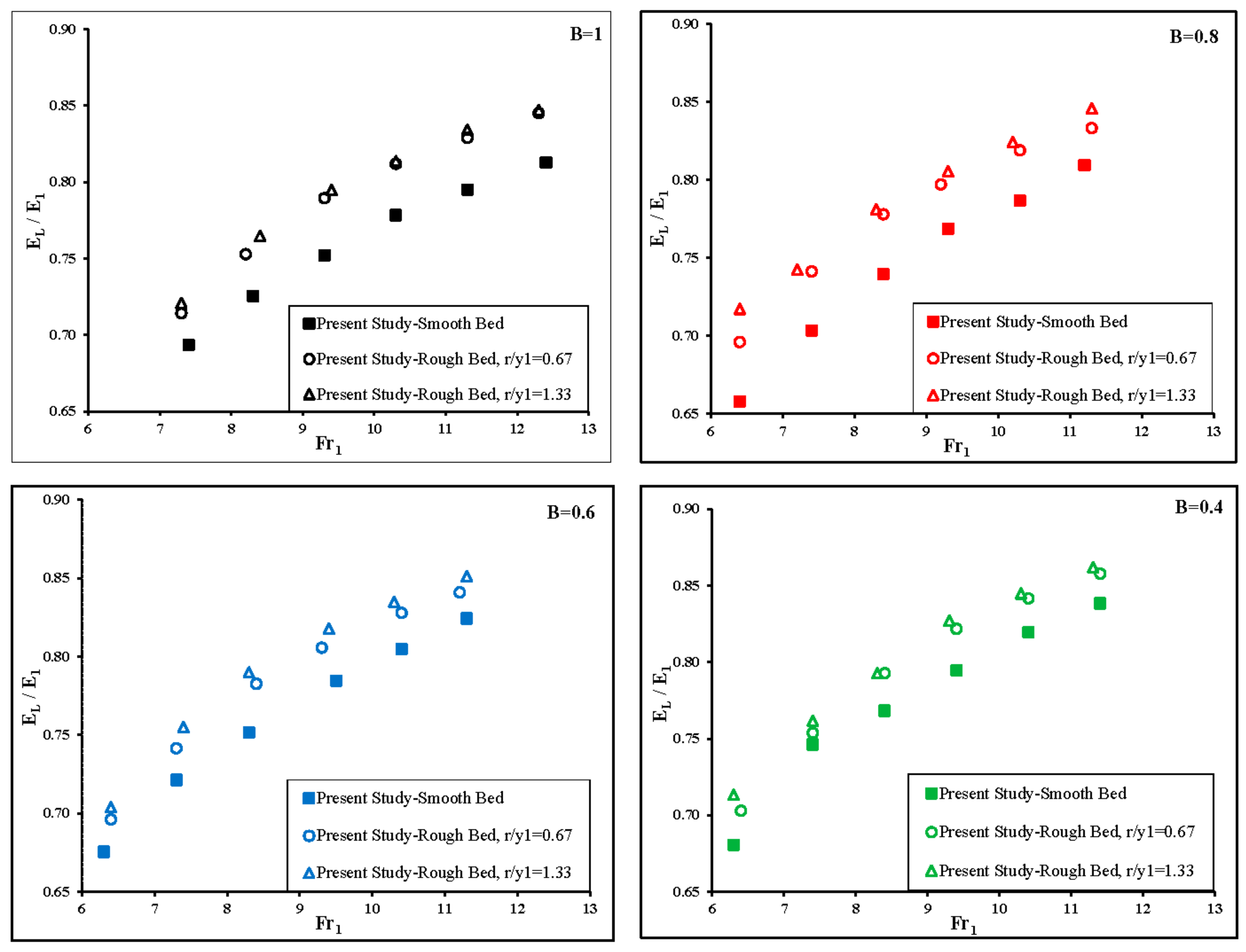
Figure 16.
(a) Variation of the relative energy loss (EL/E1) vs. the inflow Froude number for different divergence ratios on the smooth and rough bed (r/y1 = 1.33). (b) Comparison the effect of divergence ratio on relative energy loss on the smooth and rough bed (r/y1 = 0.67 and 1.33).
Figure 16.
(a) Variation of the relative energy loss (EL/E1) vs. the inflow Froude number for different divergence ratios on the smooth and rough bed (r/y1 = 1.33). (b) Comparison the effect of divergence ratio on relative energy loss on the smooth and rough bed (r/y1 = 0.67 and 1.33).

Figure 17.
Variation of the shear force coefficient () vs. the inflow Froude number for different divergence ratio (B = 1, 0.8, 0.6 and 0.4) and two relative heights of dissipative elements (r/y1 = 0.67 and 1.33).
Figure 17.
Variation of the shear force coefficient () vs. the inflow Froude number for different divergence ratio (B = 1, 0.8, 0.6 and 0.4) and two relative heights of dissipative elements (r/y1 = 0.67 and 1.33).


Table 1.
Past experimental studies on hydraulic jump.
| Reference | Cross Section and Change Bed | Flume Dimension (m) | Roughness (mm) | Range of Inflow Froude Number | Investigated Flow Properties |
|---|---|---|---|---|---|
| Hughes and Flack [19] | - Horizontal bed - Rectangular channel - Smooth and rough bed | FL = 2.13 FW = 0.3 | - Two striproughness beds (RH: 3.2 and 6.4) - Three densely packed gravel beds (RH: 4.3–11.3) | 3.44–8.04 2.34–10.5 | - Discharge - Upstream depth - Tailwater depth - Jump length - Roller length - Velocity |
| Wanoschek and Hager [23] | - Horizontal Bed - Prismatic symmetrical trapezoidal - Side slope: 45° (m = 1) | FL = 8 FW = 0.22–1.60 FH = 0.7 | - Smooth Bed | 5.45–13 | - Discharge - Upstream depth - Tailwater depth - Jump length - Velocity |
| Ead and Rajaratnam [18] | - Horizontal bed - Rectangular channel - Smooth and rough bed | FL = 7.6 FW = 0.44 FH = 0.6 | - Corrugated aluminum Sheets (RH = 13 and 22) | 4–10 | - Discharge - Upstream depth - Tailwater depth - Jump length - Roller length - Velocity - Water surface profile |
| Carollo et al. [31] | - Horizontal bed - Rectangular channel - Smooth and rough bed | FL = 1.4 FW = 0.6 FH = 0.6 | - Crashed gravel particles (d50: 4.6, 8.2, 14.6, 23.9, 32) | 1.1–9.9 | - Upstream depth - Tailwater depth - Jump length - Roller length - Velocity |
| Izadjoo and Shafai Bejestan [32] | - Horizontal bed - Two rectangular channel - Smooth and rough bed | FL = 1.2, 9 FW = 0.25, 0.5 FH = 0.4 | - Wooden baffle with trapezoidal cross section (RH: 13, 26) | 6–12 | - Upstream depth - Tailwater depth - Jump length - Velocity |
| Omid Esmaeeli Varaki [28] | - Horizontal bed - Gradually expanding channel - Trapezoidal cross section - Side slope (m): 0.5:1, 1:1, 1.5:1 - Divergence angle (ϴ): 3°, 5°, 7°, 9° | FL = 10 FW = 0.5 | - Smooth Bed | 2.99–9.83 | - Upstream depth - Tailwater depth - Jump length |
| Bejestan and Neisi [33] | - Horizontal bed - Rectangular channel - Smooth and rough bed | FL = 7.5 FW = 0.35 FH = 0.5 | - Lozenge shape rough element (RH: 16) | 4.5–12 | - Discharge - Upstream depth - Tailwater depth - Jump length - Roller length - Velocity |
| Carollo Ferro [3] | - Horizontal bed - Rectangular channel - Smooth and rough bed | FL = 4.9 FW = 0.3 FH = 0.24 | - Crushed gravel particles cemented (d50: 5.6, 9.9, 15.3, 19) | 1.7–6.9 | - Discharge - Upstream depth - Tailwater depth |
| Pagliara Lotti [21] | - Horizontal bed - Rectangular channel - Smooth and rough bed | FL = 6 FW = 0.35 FH = 0.5 | - Homogeneous and non-homogeneous sediments, gravel (d50: 6.26–45.6) - Rough bed withboulders, metallic | 2.2–12.2 | - Discharge - Upstream depth - Tailwater depth - Jump length - Roller length - Velocity - Water surface profile |
| Wang and Chanson [34] | - Horizontal bed - Rectangular channel | FL = 3.2 FW = 0.5 FH = 0.41 | - Smooth Bed | 3.8–7.5 | - Discharge - Upstream depth - Tailwater depth - Jump length - Roller length - Velocity - Air concentrations - Bubbles frequency - interfacial velocity - turbulence intensity |
Legend: FL: Flume Length, FW: Flume Width, FH: Flume Height, FS: Flume Slope, RH: Roughness Height.
Table 2.
Main characteristics of the experiments carried out in the present study.
| Experiments | b1 (m) | b (m) | b2 (m) | q (m2/s) | r (m) | Fr1 | Re1*106 | y1 (m) | V1 (m/s) | y2 (m) | Lj (m) |
|---|---|---|---|---|---|---|---|---|---|---|---|
| 1 | 0.5 | 0.5 | 0.5 | 0.0700–0.1169 | Smooth bed | 7.4–12.4 | 0.065–0.109 | 0.021 | 3.368–5.622 | 0.174–0.298 | 1.05–2.06 |
| 2 | 0.5 | 0.5 | 0.5 | 0.0701–0.1174 | 0.014 | 7.4–12.4 | 0.065–0.108 | 0.021 | 3.338–5.592 | 0.156–0.237 | 0.9–1.75 |
| 3 | 0.5 | 0.5 | 0.5 | 0.0705–0.1173 | 0.028 | 7.3–12.3 | 0.064–0.108 | 0.021 | 3.322–5.584 | 0.151–0.233 | 0.8–1.65 |
| 4 | 0.4 | 0.44–0.50 | 0.5 | 0.0619–0.1071 | Smooth bed | 6.4–11.3 | 0.056–0.097 | 0.021 | 2.946–5.098 | 0.147–0.249 | 0.8–2.3 |
| 5 | 0.4 | 0.433–0.493 | 0.5 | 0.0619–0.1071 | 0.014 | 6.4–11.3 | 0.056–0.097 | 0.021 | 2.948–5.101 | 0.127–0.219 | 0.65–1.85 |
| 6 | 0.4 | 0.428-0.48 | 0.5 | 0.0607–0.1076 | 0.028 | 6.4–11.3 | 0.055–0.097 | 0.021 | 2.889–5.125 | 0.115–0.2 | 0.57–1.6 |
| 7 | 0.3 | 0.393–0.50 | 0.5 | 0.0601–0.1076 | Smooth bed | 6.3–11.3 | 0.053–0.094 | 0.021 | 2.864–5.123 | 0.136–0.235 | 0.95–2.2 |
| 8 | 0.3 | 0.385–0.461 | 0.5 | 0.0615–0.1070 | 0.014 | 6.4–11.2 | 0.054–0.094 | 0.021 | 2.928–5.097 | 0.13–0.207 | 0.87–1.65 |
| 9 | 0.3 | 0.378–0.451 | 0.5 | 0.0610–0.1074 | 0.028 | 6.4–11.3 | 0.053–0.094 | 0.021 | 2.906–5.115 | 0.126–0.196 | 0.8–1.55 |
| 10 | 0.2 | 0.324–0.432 | 0.5 | 0.0612–0.1090 | Smooth bed | 6.3–11.3 | 0.050–0.090 | 0.021 | 2.916–5.192 | 0.136–0.221 | 0.85–1.6 |
| 11 | 0.2 | 0.302–0.396 | 0.5 | 0.0611–0.1084 | 0.014 | 6.4–11.2 | 0.050–0.089 | 0.021 | 2.910–5.160 | 0.129–0.193 | 0.7–1.35 |
| 12 | 0.2 | 0.284–0.367 | 0.5 | 0.0603–0.1070 | 0.028 | 6.4–11.3 | 0.050–0.088 | 0.021 | 2.872–5.097 | 0.119–0.183 | 0.58–1.15 |
Legend: b1 and b are the widths of the stilling basin upstream and downstream of the hydraulic jump, b2 is the width of expanded channel, q: Discharge per unit width, r: Height of the dissipative elements, Fr1: Inflow Froude number, Re1: Inflow Reynolds number, y1: Inflow depth, V1: Average velocity of upstream, y2: Sequent depth, Lj: Length of the hydraulic jump.
Table 3.
Average reduction of the sequent depth (D%).
| Experiments | D% |
|---|---|
| B = 1, r/y1 = 0.67 | 16.38 |
| B = 1, r/y1 = 1.33 | 17.88 |
| B = 0.8, r/y1 = 0.67 | 18.69 |
| B = 0.8, r/y1 = 1.33 | 23.56 |
| B = 0.6, r/y1 = 0.67 | 19.59 |
| B = 0.6, r/y1 = 1.33 | 23.67 |
| B = 0.4, r/y1 = 0.67 | 22.92 |
| B = 0.4, r/y1 = 1.33 | 27.28 |
Table 4.
Values of coefficients of a, a0 and b0 calculated from all experimental data and obtained by previous studies.
Table 4.
Values of coefficients of a, a0 and b0 calculated from all experimental data and obtained by previous studies.
| Experimental Investigation | r (cm) | B | a | a0 | b0 |
|---|---|---|---|---|---|
| Present Study | 0 | 1 | 5.24 | 2.44 | 6.02 |
| CarolloFerro [31] | 0 | 1 | 4.12 | 2.04 | 5.73 |
| Hughes and Flack [19] | 0 | 1 | 5.06 | 2.42 | 6.58 |
| Present Study | 0 | 0.8 | 5.14 | 2.48 | 5.59 |
| Present Study | 0 | 0.6 | 5.10 | 2.48 | 5.2 |
| Present Study | 0 | 0.4 | 5.07 | 2.48 | 4.84 |
| Hughes and Flack [19] | 0.32 | 1 | 4.53 | 2.25 | 5.9 |
| CarolloFerro [31] | 0.46 | 1 | 4.26 | 2.15 | 5.02 |
| Hughes and Flack [19] | 0.49 | 1 | 4.66 | 2.33 | 6.00 |
| Hughes and Flack [19] | 0.61 | 1 | 4.06 | 2.00 | 4.92 |
| Hughes and Flack [19] | 0.64 | 1 | 4.43 | 2.22 | 5.44 |
| CarolloFerro [31] | 0.82 | 1 | 3.92 | 1.98 | 4.67 |
| Hughes and Flack [19] | 1.04 | 1 | 4.07 | 2.01 | 4.79 |
| Present Study | 1.4 | 1 | 4.49 | 2.17 | 4.21 |
| Present Study | 1.4 | 0.8 | 4.85 | 2.39 | 4.39 |
| Present Study | 1.4 | 0.6 | 4.89 | 2.41 | 4.34 |
| Present Study | 1.4 | 0.4 | 4.40 | 2.20 | 3.67 |
| CarolloFerro [31] | 1.46 | 1 | 3.86 | 1.94 | 4.16 |
| Present Study | 2.8 | 1 | 4.08 | 1.98 | 3.724 |
| Present Study | 2.8 | 0.8 | 4.33 | 2.15 | 3.662 |
| Present Study | 2.8 | 0.6 | 4.55 | 2.27 | 3.789 |
| Present Study | 2.8 | 0.4 | 3.93 | 2.00 | 3.13 |
Table 5.
Equations derived in this investigation.
| Number of Equation | Equation Form | R2 | Note |
|---|---|---|---|
| 12 | 0.95 | This equation can be used for calculating sequent depth ratio in the gradually roughened stilling basin. | |
| 16 | 0.84 | This equation can be used for calculating relative roller length in the gradually roughened stilling basin. | |
| 17 | 0.86 | This equation can be used for calculating relative roller length in the gradually roughened stilling basin. | |
| 18 | 0.89 | This equation can be used for calculating the coefficient of b0 in Equation (12). | |
| 19 | 0.89 | This equation can be used for calculating relative roller length in the gradually roughened stilling basin. | |
| 22 | 0.89 | This equation can be used for calculating the relative length of the hydraulic jump in the gradually roughened stilling basin. | |
| 26 | 0.97 | This equation can be used for calculating the relative loss of energy in the gradually roughened stilling basin. |
© 2017 by the authors. Licensee MDPI, Basel, Switzerland. This article is an open access article distributed under the terms and conditions of the Creative Commons Attribution (CC BY) license (http://creativecommons.org/licenses/by/4.0/).
Share and Cite
MDPI and ACS Style
Hassanpour, N.; Hosseinzadeh Dalir, A.; Farsadizadeh, D.; Gualtieri, C. An Experimental Study of Hydraulic Jump in a Gradually Expanding Rectangular Stilling Basin with Roughened Bed. Water 2017, 9, 945. https://doi.org/10.3390/w9120945
AMA Style
Hassanpour N, Hosseinzadeh Dalir A, Farsadizadeh D, Gualtieri C. An Experimental Study of Hydraulic Jump in a Gradually Expanding Rectangular Stilling Basin with Roughened Bed. Water. 2017; 9(12):945. https://doi.org/10.3390/w9120945
Chicago/Turabian StyleHassanpour, Nasrin, Ali Hosseinzadeh Dalir, Davod Farsadizadeh, and Carlo Gualtieri. 2017. "An Experimental Study of Hydraulic Jump in a Gradually Expanding Rectangular Stilling Basin with Roughened Bed" Water 9, no. 12: 945. https://doi.org/10.3390/w9120945
Note that from the first issue of 2016, this journal uses article numbers instead of page numbers. See further details here.