Article

Failure Analysis of a Water Supply Pumping Pipeline System

by
Oscar Pozos-Estrada
*,
Alejandro Sánchez-Huerta
,
José Agustín Breña-Naranjo
and
Adrián Pedrozo-Acuña
Instituto de Ingeniería, Department of Hydraulic Engineering, Universidad Nacional Autónoma de México, Cd. Universitaria, C.P. 04510 Mexico City, Mexico
*
Author to whom correspondence should be addressed.
Water 2016, 8(9), 395; https://doi.org/10.3390/w8090395
Submission received: 1 August 2016 / Revised: 6 September 2016 / Accepted: 6 September 2016 / Published: 12 September 2016

Abstract

:
This paper describes the most important results of a theoretical, experimental and in situ investigation developed in connection with a water supply pumping pipeline failure. This incident occurred after power failure of the pumping system that caused the burst of a prestressed concrete cylinder pipe (PCCP). Subsequently, numerous hydraulic transient simulations for different scenarios and various air pockets combinations were carried out in order to fully validate the diagnostic. As a result, it was determined that small air pocket volumes located along the pipeline profile were recognized as the direct cause of the PCCP rupture. Further, a detail survey of the pipeline was performed using a combination of non-destructive technologies in order to determine if immediate intervention was required to replace PCC pipes. In addition, a hydraulic model was employed to analyze the behavior of air pockets located at high points of the pipeline.

1. Introduction

Prestressed concrete cylinder pipe (PCCP) has been successfully utilized to convey pressurized drinking water to cities and is also used in wastewater rising mains. Although PCCP is known for its good strength and capacity to resist high internal pressure and external loading, it deteriorates with time and can suffer from several problems. For example, when corrosion of the prestressing wires occurs, they eventually break reducing the strength of the pipe at that location, which creates distress in the concrete core that might lead to a catastrophic failure. Only in the USA, 435 devastating ruptures in PCCP were reported in the period of time from 1955 to 2007 [1]. Recently, Lesage and Sinclair [2] state that several municipalities in Canada and in the USA have experienced rupture of PCCP water mains, causing considerable damage.
The integrity of a PCCP is threatened internally and externally: internally by corrosion and externally by contact with aggressive soil and groundwater. The presence of inorganic or organic acids, alkalis or sulfates in the soil is directly responsible for concrete corrosion [3]. The damage to PCCP initiates with the development of cracks in the external mortar coating enabling chloride and sulfide ions to reach the prestressing wires through diffusion. While corrosion develops, the external mortar coating delaminates, which further increases the exposure of the wires to the aggressive environment. The number of wires that corrode and break increases with time, leading to eventual pipe failure when a sufficient number of wires break and the design factor of safety is compromised.
Likewise, it is well known that a hydraulic transient event can cause a serious rupture of a PCCP [4,5]. For instance, Romer et al. [1] reported 26 PCCP catastrophic failures caused by surge events around the USA. The fluid transient phenomenon over-pressurizes the pipe due to transient modification of flow rate and often this pressure is the strongest physical load a pipeline is exposed to. The pressure wave variations propagate along the pipes and induce stresses within them. In the same way, several researchers have demonstrated that the presence of air pockets in pumping pipeline systems can severely exacerbate the maximum peak pressure during transients, sufficient to cause PCCP failure.
The effect of entrapped air pockets on transient pressures may be either beneficial or destructive; depending on the air pocket volume; distribution and location; configuration of the system concerned; as well as the nature and the causes of the transient. For instance; a large air pocket can act as an effective accumulator suppressing the energy of pressure waves [6,7,8,9]. Conversely; various researchers have demonstrated that there is a considerably increase of surge pressure peaks when the air pockets are small; sufficient to cause pipe burst [10,11,12,13,14,15,16]. Small air pockets have the ability to absorb only part of the pressure wave and the majority of the wave will pass through to be reflected by the upstream and downstream boundaries. Moreover, Gahan [17] brought attention to that large and small air pocket volumes can be defined in terms of their effects on fluid transients.
Regarding the influence of small air pockets on hydraulic transients, Burrows and Qiu [12] presented case studies to illustrate its effects on pressure transients. In some cases the high peak pressures can severely arise and a catastrophic effect might be expected to occur, such as the rupture of the line. Either a single small pocket or multiple small air pockets are shown to be especially problematic. Peak pressures enhancements as high as 1.6 or even 2 times the normal steady flow duty pressures have been predicted.
In addition, Qiu and Burrows [13] stated that the presence of small air pockets in pumping pipelines might have a potential effect on fluid transients, due to an abrupt interruption of flow arising from routine pump shutdown. It is suggested that this could trigger serious implications for pipeline systems, where entrained air has not been taken into account.
Burrows [15] reported a real case study in which a pumping pipeline suffered from cracks and spillage. The author determined that the transient pressures induced by the pump shutdown would not have been the unique cause for the failures of the line. He found that a small air pocket located at an intermediate high point of the system was identified as likely to generate the enhancement of the pressure transients, experienced by a normal pump shutdown.
In the same manner, Larsen and Borrows [18] computed pressure transients and compared them with field measurements in three different pumping plastic sewer mains. The comparison highlighted the effect of air pockets at the high points of the pipelines followed by pump run-down. The authors found that only by including air pockets at the high points of the pumping systems within the numerical model could be observed that the measured and computed transient pressures adjusted reasonably well. They pointed out that air pockets can either damp or amplify the pressure transients depending on their size and causes of the transients. Accordingly, one can expect that air pockets in some situations can lead to excessive load and even rupture of the line.
Experimental investigations indicated that stationary air pockets could accumulate along the control section located at the transition between pipes with subcritical and supercritical slopes, where air valves are not located [19,20]. Although air valves have been placed, they may fail and air would not be released. In the same way, it is well known that conventional air valves quietly fail due to lack of change in their design in over the last 100 years. Therefore, these air valves may suffer premature closure or dynamic closure, in which there is tendency of the hollow floats to seal the valve fully at very low differential pressures (2 to 5 kPa or 0.2 to 0.5 mH2O) without any further discharge, resulting in the entrapment of a large volume of air in the pipeline [21].
This paper presents a preventable accident that occurred in a water supply pumping pipeline system located in Mexico. This was generated after the power failure of the pumping system causing the burst of a PCC pipe. The strongest hypothesis is that four small stationary air pockets amplified the pressure transients generating the pipe rupture. In order to fully validate the diagnostic and to investigate the destructive effect of air pockets on surge pressures in the system, a hydraulic transient analysis with entrapped air in the pumping pipeline was carried out. The methodology suggested by Pozos et al. [22] was used to identify the location of the air pockets in the pipeline and their volume was computed with a relationship based on the theory of the gradually varied flow. A detail survey of the pipeline was performed using a combination of non-destructive technologies in order to determine if immediate intervention was required to replace PCC pipes. A hydraulic model was employed to analyze the behavior of air pockets located at high points of the line.

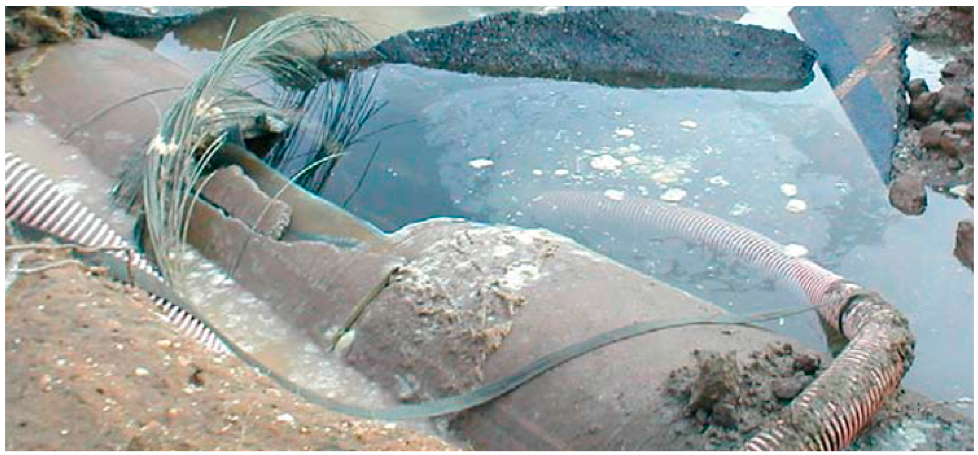
2. Pipeline Accident

The pumping pipeline investigated has a length of 3283 m and an internal diameter of 1.37 m (54 in) and was constructed of PCCP designed for 63.28 meter of water column (mH2O) (620.53 kPa = 90 psi) working pressure and a total transient pressure, consisting of working pressure plus surge pressure of 77.39 mH2O (758.42 kPa = 110 psi). A safety factor of 3 was considered during the design. The pipes consist of a 9.11 cm (3.59 in) concrete core, a nominal mortar coating thickness of 2.06 cm (0.81 in) and a thin steel cylinder of 1.55 mm (0.0610 in). As a result, the total wall thickness of the PCCP is nominally 11.18 cm (4.4 in). The pumping plant is equipped with four centrifugal pumps connected in parallel to transport a maximum water flow rate of 2.2 m3/s to a constant head tank 241.59 m above the pump sump level. An air/vacuum valve and a butterfly valve are installed at the discharge of each pump and an air chamber is located immediately downstream of each pump.
The pumping pipeline was constructed in 2000 and after 15 years of reliable operation, the pipeline experienced a serious rupture at chainage 0 + 465.80, followed by a shutdown of the four pumps. The fracture or longitudinal split occurred at the top of the PCCP, which indicates that it was caused by a severe positive peak pressure. Furthermore, most of the wires exhibited little corrosion whilst the cylinder showed only superficial corrosion, as shown in Figure 1.
There was significant structural damage to the adjacent dwellings, since a large quantity of water was released and flooded 20 homes located in a low lying area with poor drainage. In addition, four people were heavily injured by the rocks and debris transported with the current.
It is important to bring notice that records indicate that simultaneous power failure of the four pumps occurred at least twice prior to the failure, in September 2012 and April 2013. However, after these incidents the pipeline was not inspected, because the pipeline is a primary transmission system and population, industry and business depend on the imported water supply from the water authority. Therefore, there is a limited ability to shut down the pipeline for examination.
Figure 2 shows the summary of the investigations and simulations developed in order to find and identify the main causes of this incident. The actions conducted are explained within the next section.

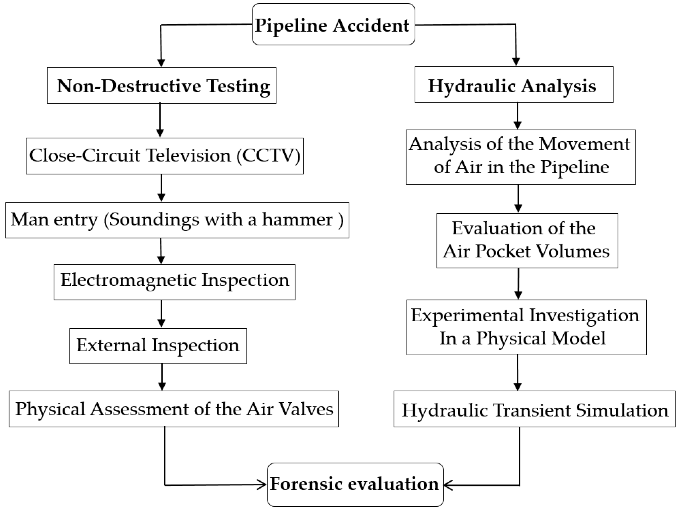
3. Materials and Methods

3.1. Field Survey

A detail field survey of the pipeline was performed by using a combination of non-destructive technologies in order to determine if immediate intervention was required to replace PCC pipes. For a comprehensive review of the current state of-the-art technologies for condition assessment of underground water and sewage pipelines, the reader is referred to Costello et al. [23] and Hao et al. [24].

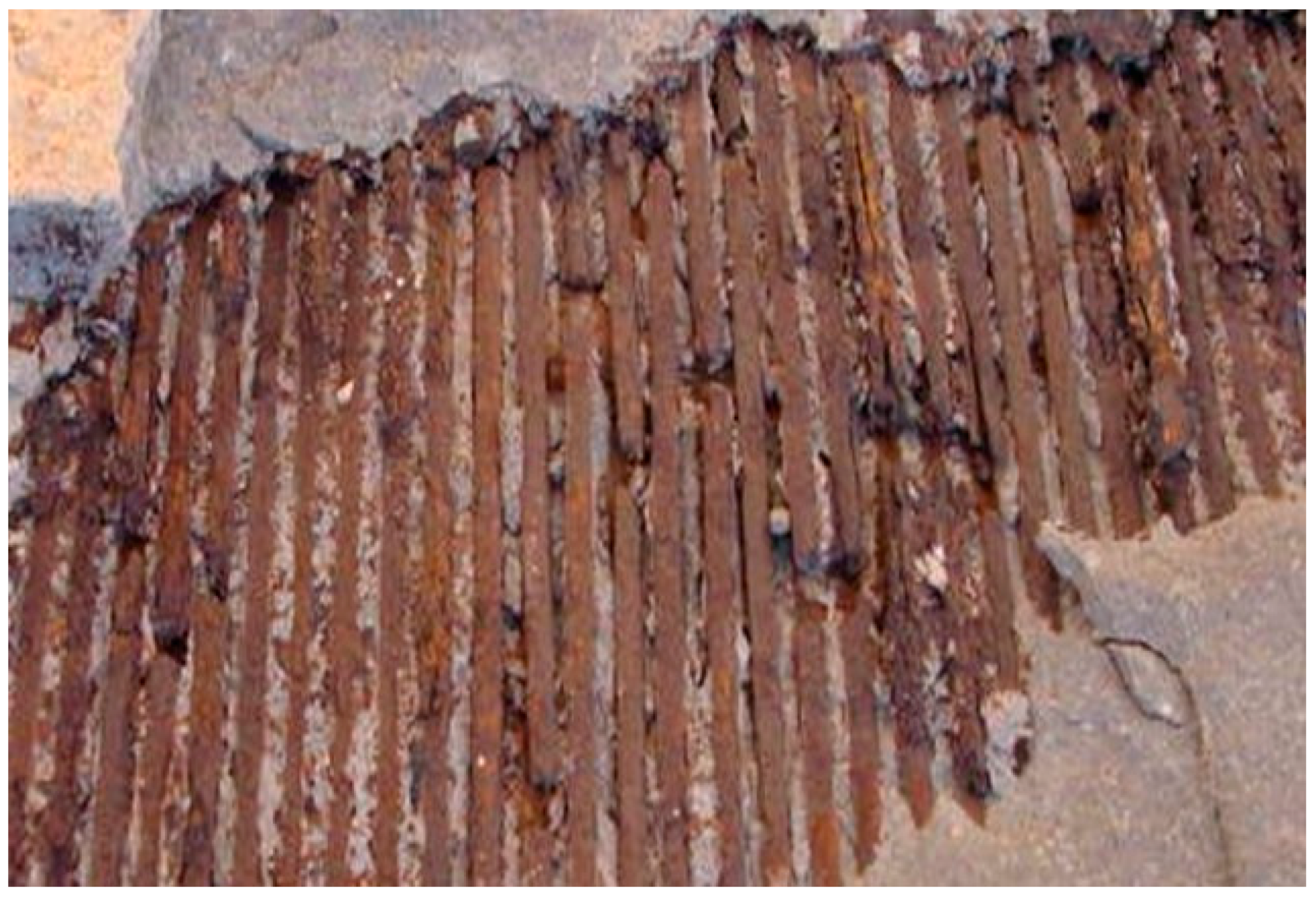
3.1.1. Non-Destructive Testing

Immediately after the accident a detailed internal examination of pipeline was made. The inspection was conducted by close-circuit television (CCTV) and man entry. It revealed 37 PCC pipes with longitudinal cracks at the crown and invert. Figure 3 illustrates the longitudinal cracks. In addition to the visual inspection, soundings with a hammer were performed along the pipeline to verify it was in good condition. Most of the pipes showed a concrete wall surface hard and dense, only three pipes in the vicinity of the rupture (station 0 + 465.80 km) and two more near a damaged air valve (station 0 + 990.42 km) presented hollow areas indicative of delamination often associated with significant wire break damage [25].
Further, an electromagnetic survey performed by others was developed throughout the pipeline, which allows for an estimation of the number of broken wires in the inspected pipes. The results were recorded on a data acquisition system. The data were subsequently analyzed and used to estimate the location and quantity of the broken wires. The survey detected 27 pipes with predicted broken prestressing wires.
The electromagnetic inspection report identified the three pipes with hollow areas located near the failure and the other two pipes close to a damage air valve as distressed pipes; they had 25 to 30 wire breaks, and, for this reason, it was recommended to repair them immediately. Fourteen pipes had 10 to 15 wire breaks and ten had five wire breaks or less. To determine the actual number of wire breaks, 27 test pits were excavated along the pipeline to completely expose the circumference of inspection, but only nine had visual damage, the other 18 did not reveal physical distress nor circumferential or longitudinal cracking of the mortar coating.
The external inspection of the five distressed pipes permitted to confirm the existence of delaminated mortar coating sections and as well as the number of corroded broken wires. The wire break estimates on individual pipe sections ranged from 18 to 37 wire breaks, all of them located at the upper half of the of the pipes. Figure 4 shows a distressed area with 20 wire breaks. The damage areas were located in the barrel of the pipes, from approximately the 10:00 o’clock to 2:00 o’clock positions. Four pipes showed longitudinal cracking of the mortar coating without distressed areas at top of the pipes with a maximum length of one meter.
It is important to bring notice that the water authority decided to replace the five distressed pipes with new PCCP. Moreover, given the catastrophic failure and that, 22 other pipe sections have electromagnetic anomalies consistent with wire break damage, permanent acoustic fiber optic was installed along the invert of the aqueduct to continuously monitor the condition of the pipes and identify pipe sections experiencing ongoing wire break activity. The wire breaks recorded by the data acquisition system are now added to the assessed wire breaks detected by the electromagnetic survey and thus at any point in the future, water authority can estimate the total number of wire breaks and the risk associated with each pipe section can be anticipated. In case a pipe section deteriorates to an unacceptable level of risk, the water authority can initiate the complete rehabilitation of a pipe section to avoid pipe failure under normal operation and reduce any additional risk during an emergency maneuver.

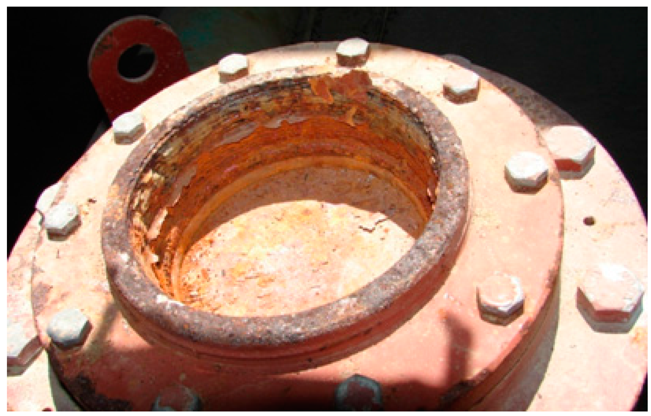
3.1.2. Physical Assessment of the Air Valves

In addition, the in situ survey revealed that a combination air valve had been misplaced at a point approximately five meter upstream from the high point due to a surveyor’s error, resulting in the accumulation of an air pocket at the station 0 + 465.80, where the pipe rupture occurred. It was also discovered that the float of the air valve located at chainage 0 + 990.42 jammed into the discharge port, it might occur either in a previous hydraulic transient event or during a filling operation of the pipeline when the valve could experience dynamic closure. Figure 5 shows the damaged valve.
A physical assessment of the combination air valves (CAV) that consist of two independent valves an air release valve and an air/vacuum valve, indicated that most of them are in some degree of submergence or corroded. The CAV installed in the investigated pipeline are conventional air valves with a typical cast iron body and hollow floats. Due to lack of change in their design in over the last 100 years, these devices may suffer dynamic closure, resulting in the entrapment of air pockets in the pipeline [21].
Following the authors’ recommendation, the water authority replaced the actual air valves for advanced, innovative devices for preventing the accumulation of air pockets and for averting the above-mentioned damages. The new air valves were re-sized; they are air release and vacuum break valves and have a small precision orifice to vent air while the pipeline is operating. The components of these valves are in corrosion free materials, the large orifices diameters equal the nominal size of the valves to reduce the resistance to the intake of air and reducing considerably the possible negative pressure within the pipeline during a draining operation. In the same way, the valves design ensures the effective removal of all air without causing dynamic closure while eliminating the possibilities of water hammer on closure of the large orifice.
It is important to highlight, that the power failure of the four pumps at the pumping station occurred at least twice prior to the pipe rupture. It is believed that the severe pressures caused by the hydraulic transients with four small air pockets experienced by the pipeline in September 2012, caused a considerable enhancement of the maximum pressure transients throughout the system, that produced longitudinal cracks at the concrete core and mortar coating of the PCCP; this allowed water to reach the steel cylinder and prestressing wires. In April 2013, the second interruption of electricity supply in the pipeline system caused the unplanned shutdown of the four pumps, this phenomenon over-pressurizes the pipes and induce stresses within them; that produced the failure of some corroded prestressing wires, which creates distress in the concrete core and the external mortar coating delaminates. Finally, after power failure occurred in September 2015, the pipeline failed (see Section 4.2 for details). This hypothesis is then investigated following the methodology addressed within the next sections.

3.2. Analysis of the Movement of Air in the Pipeline

The analytical relationship used to predict the movement of air in the investigated pipeline is supported on extensive experimental and theoretical investigations, as well as prototype analyses developed by Pozos et al. [22]. This relationship was obtained by analyzing a stable air pocket into flowing water in a downward inclined pipe, where the dimensional analysis of the momentum balance on the pocket in the inclined pipe included the balance of drag force of water and the component of the buoyant force in the direction opposite to the flow. The mentioned equation reads:
Q 2 g D 5 = S
where Q is the water flow rate and S the pipe slope with s = tanθ, where θ is the angle of pipe inclination from the horizontal, g is the gravitational acceleration and D is the inner pipe diameter. The term on the left-hand side of Equation (1) is the dimensionless water flow rate (DWFR).
For a comprehensive explanation of the development of Equation (1), as well as the projects where it has been successfully used to resolve air entrainment problems the reader is referred to Pozos et al. [22]. To establish if air pockets are prone to remain stationary at the investigated pipeline, the DWFR is evaluated for the full range of flow conditions and compared with all the pipe slopes within the pipeline. If DWFR > S, air will move in the flow direction. On the other hand, when DWFR < S, air will return upstream.
The DWFR corresponding to pipeline conditions (Q = 2.2 m3/s, D = 1.37 m, Q2/gD5 = 0.102) was compared with all the pipe slopes along the system. In this case, four stations were identified as possible candidates for air accumulation, 0 + 465.80, 0 + 990.42, 1 + 656.71 and 2 + 152.18. It is important to bring notice that at the first station, the pipe burst occurred and that at the second one the air valve failed. At the other two stations, there were not air valves installed maybe because they were not considered during the design stage. Therefore, these results reinforce the hypothesis that air pockets located at slope transitions of the investigated pipeline could be the root cause of the pipe rupture.

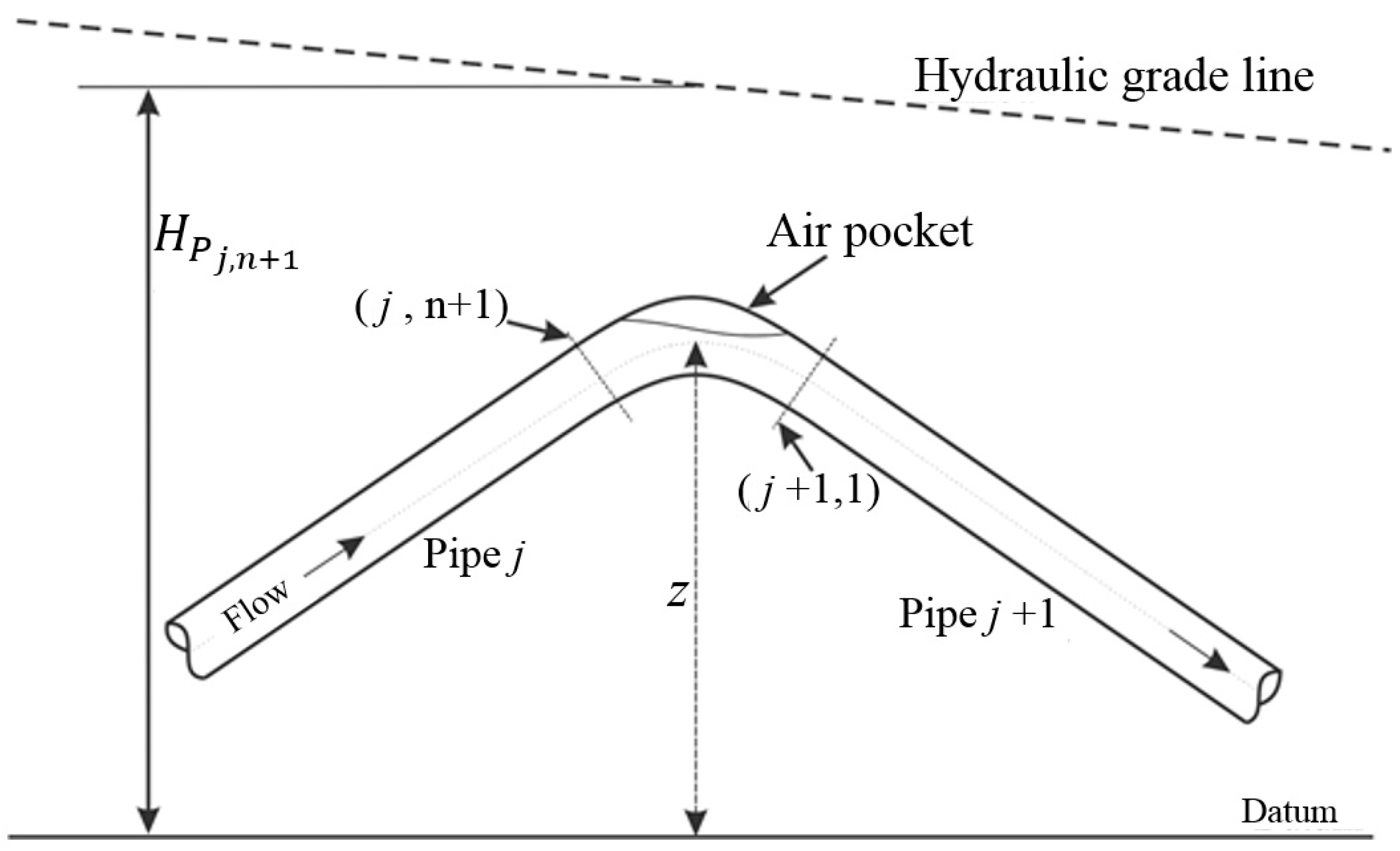
3.3. Evaluation of the Air Pocket Volume

Since there is a lack of methodologies to calculate the volume of stationary air pockets accumulated at high points of pipelines reported in the literature, Pozos et al. [26] developed an experimental investigation with the aim of deducing a relationship to compute the volume of the air pockets build-up along pipelines. Likewise, to justify the applicability of the proposed equation a theoretical study was carried out.
Pozos et al. [26] stated that the flow underneath air pockets may be considered to be analogous to flow in an open channel. The pressure on the surface of an open channel flow is atmospheric; the pressure on the air pocket surface, although not atmospheric, is constant throughout. Therefore, it was concluded that the Gradually Varied Flow theory can be used to compute the water flow profiles below the pockets. During this investigation the Direct Step Method (DSM) was applied to determine the shape of the flow profiles.
Equation (2) evaluates the air pockets volume, using the water areas and the lengths of the pipe reaches estimated with the DSM:
V = i = 1 n [ A A i A i + 1 2 ] δ x i , i + 1
where V is the air pocket volume, A is the cross section area of the pipe, δxi,i+1 is the length of the pipe reach, and Ai and Ai+1 denote the water areas at the downstream and upstream end of the pipe reach, respectively.
Equation (2) is useful to evaluate quantitatively the air pocket volumes when the flow underneath a pocket is steady. On the other hand, pipelines operate with high pressures that compress the air in the pocket. In such a case, this relationship could overestimate the volume of air. Hence, it should be used with caution. Nevertheless, this equation is suitable to approximate the volume of the stationary air pockets, because air accumulated in pipelines is unknown and cannot be observed.

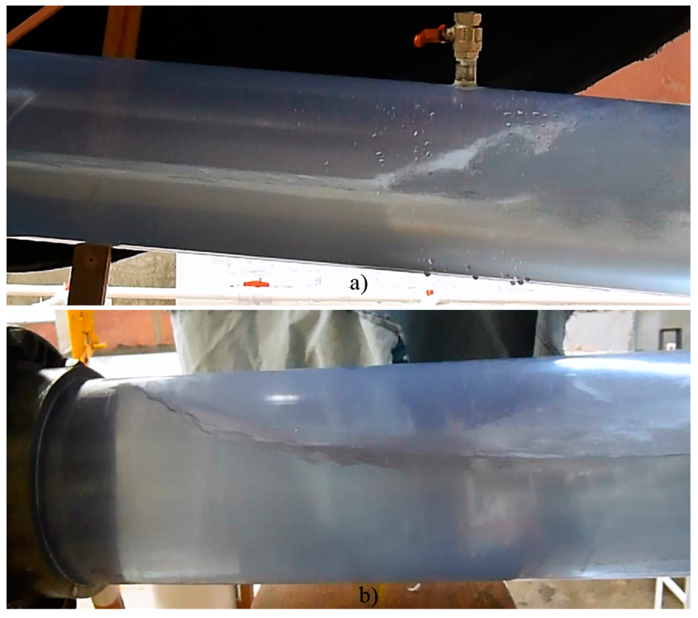
3.4. Experimental Investigation

An experimental setup was implemented to further analyze air pocket accumulation at the slope transitions of the investigated pipeline and to support the results obtained with the relationship suggested by Pozos et al. [22]. The physical model was scaled (1:6.86) following the Froude similarity owing to presence of free surface flow in the pipeline.
Pothof and Clemens [27], Pothof and Clemens [28] and Pothof [29] stated that surface tension effects can be considered negligible when the Eötvös number E = γD2/σ is greater than 5000 (or D > 191 mm). Therefore, the test section of the model consisted of a 12 meter long clear PVC pipe with an internal diameter of 200 mm. The flow was pumped from a constant head tank. The water flow rate was measured by an electromagnetic flowmeter. Tapping points were installed along the test section to allow the injection of air either with a piston with an air capacity of 1 L or a compressor. The clear PVC pipes were connected by a flexible hose to adjust easily the required pipe slopes.
The upward and downward inclined pipe sections of the test facility were set at different sub- and supercritical slopes to simulate the slope transitions identified as control sections of the stationary air pockets in the investigated pumping pipeline. The prototype water flow rate was 2.2 m3/s, corresponding to 17.8 L/s (0.0178 m3/s) model discharge. When the test section of the experimental apparatus was flowing full, the air was injected through the tapping points, forming air pockets that accumulated at the slope transition of the model.
The experimental observations confirmed that the air pockets remain at the transition of slope for the water flow rate. The water flow below the pockets behaved as open channel flow. The test section is equivalent to a pair of connected prismatic channels with the same cross section but with different slopes. At the upstream leg of the experimental apparatus the flow profiles were very similar as the profiles at open channels with adverse and mild slope (Sup). The control section occurred at the downstream end of the subcritical slope, since the flow in a steep channel has to pass through the critical control section at the upstream end and then follows the S2 profile (Sdown) ending in a hydraulic jump, the subscripts “up” and “down” relate to the up- and downstream pipe portions, respectively.
Figure 6 shows the flow profiles A2 (Sup = −0.141) and S2 (Sdown = 0.109) simulated in the hydraulic model. Part of the results obtained during the tests is summarized in Table 1. It is important to highlight that the length of the air pocket profiles remain constant upstream of the control section and the pocket will continue growing only in the downstream direction when more air is injected as observed by Walski et al. [19] and Pozos et al. [20] during their investigations. In addition, the test section of the apparatus operated at pressures slightly higher than the atmospheric pressure in Mexico City (Patm = 8.03 mH2O).

3.5. Hydraulic Transient Simulation

The hydraulic transient simulation was conducted using the numerical model, PTPSliv.for, developed by Qiu [30]. The computational model is based on the momentum and mass conservation equations (Equations (3) and (4)) to the water phase. Details of the program PTPS are given in [17] and a comprehensive review of the program can be found in [30]. For the projects where it has been successfully used to analyze hydraulic transients with entrapped air, the reader is referred to [13,15,31,32].
Q t + g A H x + f 2 D A Q | Q | = 0
a 2 g A Q x + H t = 0
where H is the piezometric head, Q is the water flow rate, A is the cross-section flow area, D is the pipe diameter, a is the celerity of the pressure wave, x is the spatial coordinate along the pipeline, t is the time, g is acceleration due to gravity and f is the Darcy–Weisbach friction factor.
A general solution to the hyperbolic partial differential Equations (3) and (4) is not available. The method of characteristics (MOC) is applied to convert the momentum and mass equations into ordinary differential equations. These are then solved along the characteristic lines by expressing them in finite-difference form, which can be solved without interpolation to eliminate numerical instability. The flow remains homogenous and free of entrained air, such that wave propagation velocity remains invariant during the transient analysis. Further, the Courant condition (∆x ≥ a∆t) was satisfied during all simulations. A more comprehensive review of the MOC can be found in [9,33,34].
Numerical models based on the MOC are known to give accurate results and have demonstrated to be effective [35,36,37]. They have been successfully applied in the design of pumping pipelines involving transient cavitation and air pockets [12,15,18].
In the same way, to study the effect of the air pockets in hydraulic transients they are considered as boundary conditions in the model. For computational convenience, the position of the pockets is restricted to node points, representing junctions between adjacent pipe reaches. It is important to highlight that the pockets are considered as accumulators, where the pressure at any instant is the same throughout the air volume. The compressibility of the liquid in the accumulator can be neglected since it is very small compared with the air compressibility. Further, inertia and friction are ignored.
The air enclosed at the pocket or accumulator is assumed to follow the reversible polytropic relation (Equation (5)) (Wylie et al. [34]):
H A b s V m = k
where HAbs is the absolute head in the pocket and is equal to the gauge pressure at the corresponding nodal points plus atmospheric pressure, V is the air volume in the pocket, k is a constant whose value is evaluated from the initial steady state condition for the air pocket, and m is the polytropic exponent that ranged from 1.0 to 1.4. In this study, m = 1.4 was employed, since various researchers have demonstrated experimentally and numerically that hydraulic transients with entrapped air pockets are better predicted with a polytropic exponent m = 1.4 [38,39,40].
Since Equation (5) may apply at any instant, it can be written for the junction (j, n + 1) at the end of the time increment ∆t, as shown in Equation (6). For the junctions (j, n + 1) and (j + 1,1), the first subscript refers to the pipe sections between input topographical coordinates and the second subscript denotes further subdivisions into reaches, of the jth and (j + 1)th pipe sections. Figure 7 shows the notation for the air pocket.
( H P j , n + 1 + H b z j , n + 1 ) ( V j , n + 1 + Δ V j , n + 1 ) m = k 1
where HPj,n+1 is the piezometric head above the datum, Hb the barometric pressure head, zj,n+1 is the height of the pipe axis above the datum, Vj,n+1 is the volume of the air pocket at the beginning of the time step ∆t, and ∆Vj,n+1 is the air volume change during the time interval. The continuity equation for the junction becomes:
Δ V j , n + 1 = Δ t 2 [ ( Q P j + 1 , 1 + Q j + 1 , 1 ) ( Q P j , n + 1 + Q j , n + 1 ) ]
where Qj,n+1 and QPj,n+1 are the water flow rates at the upstream end of the air pocket at the beginning and end of the time step, respectively; and Qj+1,1 and QPj+1,1 are the water flow rates at the downstream end of the air pocket at the beginning and end of the time step, respectively. Noting that the variables with subscript P indicate that these are unknown at the time t + ∆t. Finally, to investigate the effect of the air pockets in hydraulic transients, Equation (6) yields:
( H P j , n + 1 + H b z ) [ V j , n + 1 + Δ t 2 { ( Q j + 1 , 1 Q j , n + 1 + C C + ) + ( B j + B j + 1 ) H P j , n + 1 } ] m = k 1
where C+ and C are the so-called characteristic lines and B is a coefficient, defined as B = a/gA. Likewise, HPj,n+1 is the only unknown in Equation (8), which is not linear and the method of Newton–Raphson is employed for solution.
In addition, the following assumptions were made during the implementation of the numerical model Qiu [30]: (1) air pockets will not lead to water column separation during the transients, because they never occupy the entire cross section of the pipe; (2) it is supposed that the air pockets remain at the slope transitions during the transient simulation, since the movement of free air can be neglected in comparison with the quick phenomenon of the travel of pressure waves; and (3) no gas release and absorption take place during the transients.
Prior to the simulation, Equations (1) and (2) were used to find the potential stations susceptible to build up air pockets along the investigated pipeline and to compute the air pocket volumes, respectively. The results obtained are summarized in Table 2. The pipe slopes S correspond to the downward sloping pipes, where the air bubbles/pockets will return relative to the current, and then air will collect at the upstream end of the downgrade pipe. Likewise, after several simulations, transient pressures achieved showed that small volumes of air are the critical air pocket sizes.
Afterwards, a series of numerical transient simulations by using the numerical model were developed to find the worst-case scenarios. The most critical situation is that when the pumping plant operates with four pumps and the four small air pocket volumes summed up in Table 2 are placed at the stations identified in the analysis. In addition, to compare the hydraulic transients with and without entrapped air in the pumping pipeline, the sudden shutdown of the pumps due to power failure was simulated without considering air accumulated. The maximum and minimum head envelopes achieved with and without regarding air are plotted in Figure 7.

4. Results and Discussion

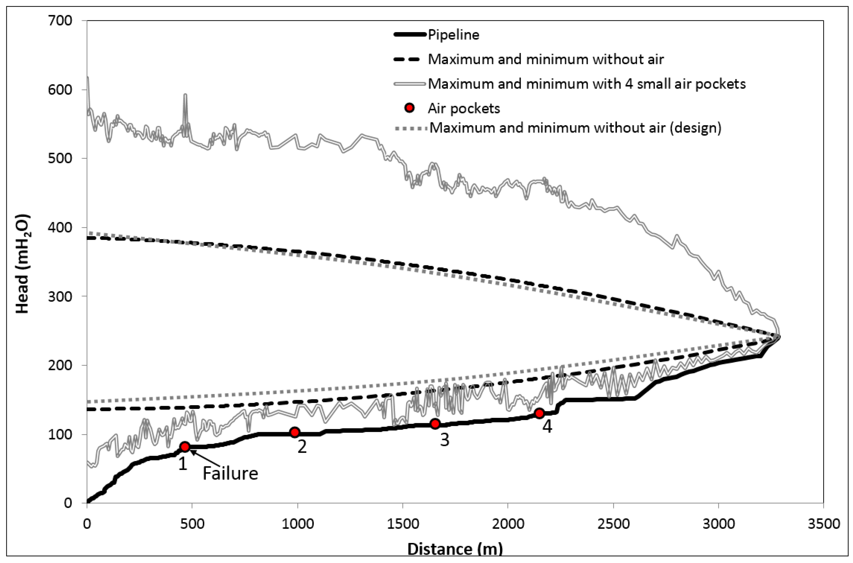
4.1. Simulation Analysis

Because there were no pressure recorders in the failure area, a hydraulic transient analysis was performed to estimate the magnitude of the pressure increases that may have occurred near the failure location. The analysis started with a simulation of a transient event caused by power failure for the four pumps in the plant without considering air pockets. It is important to highlight that the results of the numerical simulation shows a suitable design of the pumping pipeline due to the highest pressures did not surpass the design pressure transients achieved for the same scenario in the length of line affected, as can be observed in Figure 8.
In contrast to the above mentioned, the presence of the four small air pocket volumes occasioned the worst consequence in the investigated pipeline, they caused a considerable heightening of the maximum and minimum head envelopes along the system (see Figure 8). The results show that these pockets absorbed only a part of the transient pressure wave and the rest is reflected and amplified towards the boundaries, the butterfly valves at the discharges of the pumps at upstream end and the constant head tank at downstream end of the pipeline.
It is also observed from the minimum head envelopes (with and without air) that the system never experience subatmospheric pressure that could lead to water column separation. Therefore, it can be discarded that the pressures generated when the separated columns rejoin caused the PCCP failure.
Figure 8 also shows that the upstream air pocket location gives the highest transient pressures at the pump exit. This is possibly as a result of the effect of reflection of the transient wave by the small air pocket, since it suppresses only partially the energy of pressure waves, this contributes to an accumulation effect. In addition, the influence of the small pocket further downstream is that the transient pressures have reached their maximum value earlier, and, therefore, amplification of the pressures is lower [17].
In the same way, the critical pressure at which the PCCP could fail was estimated to be 510.93 m of water column (5012.19 kPa = 726.96 psi). This critical pressure occurred at station 0 + 465.80 was 41.86% higher than that caused by the pumps shutdown without regarding air pockets. This increase in pressure could be enough to generate the pipe burst, due to the permissible pressure assumed for the design and construction of the investigated pipeline with a safety factor of 3 is 420.99 m (4130 kPa = 600 psi).

4.2. Probable Failure Sequence

The authors suggested the existence of four small air pockets at changes of slope of the investigated pipeline, since the occurrence of the first simultaneous power failure of the four pumps in September 2012. It is believed that during this surge event the severe pressures caused by the hydraulic transients with entrapped air experienced by the pipeline produced the longitudinal cracks in the concrete core and mortar coating of some undamaged PCCP.
Likewise, Ge and Sinha [41] developed a structural analysis of a 60-inch (1.52 m) PCC pipe with an internal pressure rating of 98.85 mH2O (940 kPa = 137 psi) for different scenarios by using a three-dimensional (3D) finite element model (FEM). The authors analyzed the stress level in the pipe to understand when the concrete core starts cracking. In this study, the loadings such as internal water pressure, the weight of the earth and pipe were considered, as well as PCCP components such as mortar coating, concrete core, prestressing wires, steel saddle, and cylinder. The results indicated that if the prestressing wires are full prestress the maximum principal stress distribution in concrete core and mortar coating occurs at the crown and invert.
Based on the findings of Ge and Sinha [41] and the results obtained during the transient simulation with four small air pockets, it was found that the maximum internal water pressure is equal to 5012.19 kPa, which is higher than the tensile strength of concrete (4020 kPa). Therefore, the internal pressure could have been enough to enhance the maximum principal stress distribution in concrete core and mortar coating to generate the cracks at the pipeline. This could explain the longitudinal cracks found at crown and invert of some pipeline sections during the field survey.
Once the cracks appeared at the concrete core and mortar coating, the treated water with chlorine could penetrate into the pipe and corrode the steel cylinder, since the cylinder has contact with inner core. In the same way, the cracks at the mortar coating allow groundwater intrusion and also enabling chloride and sulfide ions to reach the prestressing wires and cylinder through diffusion, facilitating corrosion [3].
In April 2013, the second power failure of the four pumps occurred at the pumping plant; likewise, the pipeline could withstand the high internal pressure generated by the transient event with entrapped air. However, this phenomenon over-pressurizes the pipes and induce stresses within them; the increase in the stresses in the wires produced the failure of some corroded prestressing wires, since a relatively small amount of corrosion can cause a wire to break [42]. When wires break the strength of the pipe is reduced, which creates distress in the concrete core and the external mortar coating delaminates.
In September 2015, more than two years after the last transient event, once again occurred the simultaneous shutdown of the four pumps. Further, it is considered that the cracks at the inner concrete core and the mortar coating, the corroded steel cylinder, and eventual breakage of enough wires at the barrel led to reduce the strength of the pipe. Hajali et al. [43] and Hajali et al. [44] investigated the effect of the number and location of broken wire wraps on the structural performance of a 96-inch (2.44 m) PCCP with an internal pressure rating of 87.69 mH2O (860 kPa = 125 psi) by using advanced numerical modeling (3D-FEM). The stresses and strains in the various components of PCCP are evaluated with increasing internal fluid pressure. They found that with only five broken wire wraps at the barrel of the PCC pipe the cracking in the concrete core and in the mortar coating occurs at 140.52 mH2O (1379 kPa = 200 psi) and at 154.58 mH2O (1517 kPa = 220 psi) internal fluid pressure, respectively. The rupture for the prestressing wire wraps takes place at internal fluid pressures of 234.37 mH2O (2300 kPa = 334 psi). Therefore, based on the above, it is believed that the maximum transient pressure equal to 510.93 mH2O (5012.19 kPa = 726.96 psi) that occurred at station 0 + 465.80 was enough to generate the pipe rupture.
It is important to highlight that a structural analysis was not conducted due to the lack of pipe material data. Likewise, it can be expected that the findings of Ge and Sinha [41], Hajali et al. [43] and Hajali et al. [44] remain valid for the Class 90-14 54-in. PCCP of the investigated pipeline.

5. Recommendations

Based on the results of the forensic evaluation, it can be stated that the sudden and catastrophic failure of the pipe at station 0 + 465.80 is the result of a combination of factors. During the pipeline construction a combination air valve had been misplaced, conventional air valves with hollow floats were installed and one of this devices suffered from dynamic closure and the float jammed into the orifice. In the same way, two small air pockets accumulated at two high points (stations 1 + 656.71 and 2 + 152.18) where air valves were not located. Furthermore, the power failure of the four pumps occurred at least twice (September 2012 and April 2013) before the pipe rupture, unfortunately, after these hydraulic transient events the pipeline was not inspected. It is considered that the severe internal pressure transients created longitudinal cracks in the concrete core and mortar coating, enabling the water to corrode the wires and cylinder, and after some months the prestressing wires break. Finally, in September 2015, the unexpected shutdown of the four pumps caused the catastrophic failure of the pipeline.
Although the water authority replaced the five distressed pipe sections, installed permanent acoustic fiber optic along the invert of the pipeline to continuously track the time and location of wire breaks in the prestressing wire of the pipes, and made the replacement of the conventional air valves with advance devices for preventing the accumulation of air pockets. It is recommended to perform additional works to reduce risk of failure in the future.
Given the performance history of the pumping pipeline, the water authority should implement the following actions for this system; the activities are numbered in order of priority from authors’ engineering judgment:
(1) A laboratory analysis should be performed to the failed pipe and the five distressed pipes replaced, with the main aim of evaluating the condition of the mortar, prestressing wires, and the steel cylinder.
(2) Develop a structural analysis of the pipeline based on the electromagnetic testing, using Finite Element Analysis to determine the capacity of the damaged pipeline segments and to determine future repair priorities.
(3) A transient pressure monitoring system should be installed; it can reliably detect the presence of a pressure transient in the pipeline to have better understanding about behavior of the system. Under steady and unsteady flow conditions, the pressure monitoring system samples pressure data that could be useful for a detail analysis in case of future pipeline failures.
(4) An additional longitudinal and circumferential strength should be provided to the 22 pipe sections with wire break damage. The strengthening method recommended is the Carbon Fiber Reinforced Polymer (CFRP) to line the interior of the pipes.
(5) Soil corrosivity testing in the full length of the pipeline to determine corrosion damage and to identify areas of corrosion activity to install cathodic protections.
(6) External and internal inspection once a year, during low demand periods. The inspections have to be closely coordinated and well planned to allow time to drain, inspect and fill the pipeline. Technologies and inspection techniques are available to reliably assess the condition of these systems so that problematic sections of pipe can be identified and repaired prior to failure.
(7) Electromagnetic calibration of pipeline segments for future surveys. When feasible, it is advisable to perform a calibration of the electromagnetic inspection equipment on the pipeline to be inspected. Calibration involves cutting a known amount of prestressing wire wraps on a pipe section and performing an electromagnetic test to determine the electromagnetic response to a known level of damage in a pipe section. Numerous wire cut scenarios are created and electromagnetic signatures are obtained for each of them. This type of calibration provides the most accurate reliable electromagnetic inspection results.
As a result, it is clear that proactive assessment and management of pipelines can extend the service life of these systems, avoiding outages because of unexpected failures.

6. Conclusions

Based on the forensic evaluation, the failure does not appear to have been caused by a single factor but by a combination of several factors that include air accumulation in the pipeline, power loss events, and installation of conventional air valves. Likewise, after the unexpected shutdowns of the four pumps that occurred in September 2012 and April 2013 the pipeline was not inspected. The accident could have been avoided if there had been better coordination during the design process, system construction and operation.
The accident under consideration should be a warning that in pumping pipelines, even those equipped with air valves, there is a real danger of a pipe burst caused by severe transient pressures, when power failure occurred in a pumping plant and there are small air pockets located along the pipeline profile. To prevent these situations, it is desirable to analyze the potential destructive effects of air pockets on hydraulic transients for various conditions of pumps operation as a matter of routine during design stage of pumping systems.
The severe pressure transients achieved by the hydraulic transient analysis with entrapped air appears to ratify the PCCP failure diagnostic and show that the small air pocket volumes located at points 1 to 4 (Figure 8) of the pumping pipeline have the potential harmful effect to exacerbate pressure transients that could lead to the pipeline rupture, since during the transient simulation of the simultaneous power failure of the four pumps regarding entrapped air, the pressures in the whole length of the pipeline remain above allowed working pressure.
In the case of the damaged air valve and the air valve that was misplace, they were directly responsible for the pipe rupture, since they aggravated the transient pressures during the power failure, because of the entrapment of air in the pipeline. It was therefore recommended to change the actual air valves to modern ones for preventing the accumulation of air pockets and for averting the above-mentioned accident. Further, the installation of permanent acoustic fiber optic will help the water authority to avoid pipe failure under normal operation and reduce any additional risk during an emergency operation.
Finally, it was recommended to perform additional works to reduce risk of failure in the future.

Author Contributions

Oscar Pozos-Estrada simulated the accident according to the data; Oscar Pozos-Estrada, Alejandro Sánchez-Huerta, José Agustín Breña-Naranjo and Adrián Pedrozo-Acuña analyzed, discussed and interpreted the results; Oscar Pozos-Estrada and Alejandro Sánchez-Huerta wrote the paper. José Agustín Breña-Naranjo and Adrián Pedrozo-Acuña reviewed the manuscript.

Conflicts of Interest

The authors declare no conflict of interest.

References

  1. Romer, A.E.; Ellison, D.; Bell, G.E.C.; Clark, B. Failure of Prestressed. Concrete Cylinder Pipe; AWWA Research Foundation: Washington, DC, USA, 2008. [Google Scholar]
  2. Lesage, J.C.; Sinclair, A.N. Characterization of Prestressed Concrete Cylinder Pipe by Resonance Acoustic Spectroscopy. J. Pipeline Syst. Eng. Pract. 2014, 6. [Google Scholar] [CrossRef]
  3. Oualit, M.; Jauberthie, R.; Rendell, F.; Melinge, Y.; Abadlia, M.T. External Corrosion to Concrete Sewers: A Case Study. Urban Water J. 2012, 9, 429–434. [Google Scholar] [CrossRef]
  4. Romer, A.E.; Bell, G.E.; Ellison, R.D. Failure of Prestressed Concrete Cylinder Pipe. In Proceedings of the Pipeline Engineering and Construction, Boston, MA, USA, 8–11 July 2007.
  5. Woodcock, M. 48-Inch PCCP Pipeline Break; Technical Report; Washington Suburban Sanitary Commission: Laurel, MD, USA, 2008. [Google Scholar]
  6. Martin, C.S. Entrapped Air in Pipelines. In Proceedings of the Second International Conference on Pressure Surges, London, UK, 22–24 September 1976; pp. 15–28.
  7. Martin, C.S. Two-phase gas-liquid experiences in fluid transients. In Proceedings of the 7th International Conference on Pressure Surge and Fluid Transients in Pipelines and Open Channels, Harrogate, UK, 16–18 April 1996; pp. 65–81.
  8. Stephenson, D. Effects of Air Valves and Pipework on Water Hammer Pressure. J. Transp. Eng. 1997, 123, 101–106. [Google Scholar] [CrossRef]
  9. Thorley, A.R.D. Fluid Transients in Pipeline Systems, 2nd ed.; John Wiley & Sons: London, UK, 2004. [Google Scholar]
  10. Jönsson, L. Maximum Transient Pressures in a Conduit with Check Valve and Air Entrainment. In Proceedings of the International Conference on the Hydraulics of Pumping Stations, Manchester, UK, 17–19 September 1985; pp. 55–76.
  11. Jönsson, L. Anomalous Pressure Transients in Sewage Lines. In Proceedings of the International Conference on Unsteady Flow and Transients, Durham, UK, 29 September–1 October 1992; pp. 251–258.
  12. Burrows, R.; Qiu, D.Q. Effect of Air Pockets on Pipeline Surge Pressure. Proc. Inst. Civ. Eng. Water Marit. Energy 1995, 112, 349–361. [Google Scholar] [CrossRef]
  13. Qiu, D.Q.; Borrows, R. Prediction of Pressure Transients with Entrapped Air in a Pipeline. In Proceedings of the 7th International Conference on Pressure Surge and Fluid Transients in Pipelines and Open Channels, Harrogate, UK, 16–18 April 1996; pp. 251–263.
  14. Izquierdo, J.; Fuertes, V.S.; Cabrera, E.; Iglesias, P.L.; Garcia-Serra, J. Pipeline Start-Up with Entrapped Air. J. Hydraul. Res. 1999, 37, 579–590. [Google Scholar] [CrossRef]
  15. Burrows, R.A. Cautionary Note on the Operation of Pumping Mains Without Appropriate Surge Control and the Potentially Detrimental Impact of Small Air Pockets. In Proceedings of the IWA International Conference, Valencia, Spain, 22–25 April 2003.
  16. Pozos, O. Investigation on the Effects of Entrained Air in Pipelines. Ph.D. Thesis, University of Stuttgart, Stuttgart, Germany, 2007. [Google Scholar]
  17. Gahan, C.M. A Review of the Problem of Air Release/Collection in Water Pipelines with In-Depth Study of the Effects of Entrapped Air on Pressure Transients. Master’s Thesis, University of Liverpool, Liverpool, UK, 2004. [Google Scholar]
  18. Larsen, T.; Burrows, R. Measurements and Computations of Transients in Pumped Sewer Plastic Mains. In Proceedings of the International Conference on Pipeline Systems, Manchester, UK, 24–26 March 1992; pp. 117–123.
  19. Walski, T.M.; Barnhart, T.; Driscoll, J.; Yencha, R. Hydraulics of Corrosive Gas Pockets in Force Mains. Water Environ. Res. 1994, 66, 772–778. [Google Scholar] [CrossRef]
  20. Pozos, O.; Giesecke, J.; Marx, W.; Rodal, E.A.; Sanchez, A. Experimental Investigation of Air Pockets in Pumping Pipeline Systems. J. Hydraul. Res. 2010, 48, 269–273. [Google Scholar] [CrossRef]
  21. Thomas, S. Air Management in Water Distribution Systems: A New Understanding of Air Transfer; Clear Water Legacy: Burlington, ON, Canada, 2003. [Google Scholar]
  22. Pozos, O.; González, C.A.; Giesecke, J.; Marx, W.; Rodal, E.A. Air Entrapped in Gravity Pipeline Systems. J. Hydraul. Res. 2010, 48, 338–347. [Google Scholar] [CrossRef]
  23. Costello, S.B.; Chapman, D.N.; Rogers, C.D.F.; Metje, N. Underground Asset Location and Condition Assessment Technologies. Tunn. Undergr. Space Technol. 2007, 22, 524–542. [Google Scholar] [CrossRef]
  24. Hao, T.; Rogers, C.D.F.; Metje, N.; Chapman, D.N.; Muggleton, J.M.; Foo, K.Y.; Wang, P.; Pennock, S.R.; Atkins, P.R.; Swingler, S.G.; et al. Condition Assessment of the Buried Utility Service Infrastructure. Tunn. Undergr. Space Technol. 2012, 28, 331–344. [Google Scholar] [CrossRef]
  25. Higgins, M.S.; Gadoury, P.J.; LePage, P.; Razza, R.; Jack Keaney, P.E.; Mead, I. Technologies to Assess and Manage Providence’s Water’s 102 Inch PCCP Aqueduct. In Proceedings of the Pipelines 2007, Boston, MA, USA, 8–11 July 2007; pp. 1–8.
  26. Pozos, O.; Sanchez, A.; Rodal, E.A.; Fairuzov, Y.V. Effects of Water-Air Mixtures on Hydraulic Transients. Can. J. Civ. Eng. 2010, 37, 1189–1200. [Google Scholar] [CrossRef]
  27. Pothof, I.W.M.; Clemens, F.H.L.R. On Elongated Air Pockets in Downward Sloping and Inclined Pipes. J. Hydraul. Res. 2010, 48, 499–503. [Google Scholar] [CrossRef]
  28. Pothof, I.W.M.; Clemens, F.H.L.R. Experimental Study of Air-Water Flow in Downward Sloping Pipes. Int. J. Multiph. Flow 2011, 37, 278–292. [Google Scholar] [CrossRef]
  29. Pothof, I.W.M. Co-current Air-Water Flow in Downward Sloping Pipes, Transport of Capacity Reducing Gas Pocket in Wastewater Mains. Ph.D. Thesis, Delft University of Technology, Delft, The Netherlands, 2011. [Google Scholar]
  30. Qiu, D.Q. Transient Analysis and the Effect of Air Pockets in a Pipeline. Master’s Thesis, University of Liverpool, Liverpool, UK, 1995. [Google Scholar]
  31. Escarameia, M. Air Problems in Pipelines: A Design Manual; HR Wallingford: Wallingford, Oxfordshire, UK, 2005. [Google Scholar]
  32. Escarameia, M.; Dabrowski, C.; Gahan, C.; Lauchlan, C. Experimental and Numerical Studies on Movement of Air in Water Pipelines; HR Wallingford: Wallingford, Oxfordshire, UK, 2005. [Google Scholar]
  33. Chaudhry, M.H. Applied Hydraulic Transients, 2nd ed.; Van Nostrand Reinhold: New York, NY, USA, 1987. [Google Scholar]
  34. Wylie, E.B.; Streeter, V.L.; Suo, L. Fluid Transients in Systems; Prentice Hall: Englewood Cliffs, NJ, USA, 1993. [Google Scholar]
  35. Ivetic, M.V. Forensic Transient Analyses of Two Pipeline Failures. Urban Water J. 2004, 1, 85–95. [Google Scholar] [CrossRef]
  36. Fernandes, C.; Karney, B. Modelling the Advection Equation under Water Hammer Conditions. Urban Water J. 2004, 1, 97–112. [Google Scholar] [CrossRef]
  37. Almeida, A.B.; Ramos, H.M. Water Supply Operation: Diagnosis and Reliability Analysis in a Lisbon Pumping System. J. Water Supply Res. Technol. 2010, 59, 66–78. [Google Scholar] [CrossRef]
  38. Lee, N.H.; Martin, C.S. Experimental and Analytical Investigation of Entrapped Air in a Horizontal Pipe. In Proceedings of the 3rd ASME/JSME Joint Fluids Engineering Conference, San Francisco, CA, USA, 18–23 July 1999.
  39. Martin, C.S.; Lee, N.H. Rapid Expulsion of Entrapped Air through an Orifice. In Proceedings of the 8th International Conference on Pressure Surges-Safe Design and Operation of Industrial Pipe Systems, The Hague, The Netherlands, 12–14 April 2000; pp. 125–132.
  40. De Martino, G.; Giugni, M.; Viparelli, M.; Gisonni, C. Pressure Surges in Water Mains Caused by Air Release. In Proceedings of the 8th International Conference on Pressure Surges-Safe Design and Operation of Industrial Pipe Systems, The Hague, The Netherlands, 12–14 April 2000; pp. 147–159.
  41. Ge, S.; Sinha, S.K. Analysis of a 60-In. PCCP that Failed without Warning from Acoustic Fiber Optic System. In Proceedings of the Pipeline 2014, Portland, OR, USA, 3–6 August 2014; pp. 84–95.
  42. Holley, M.; Diaz, B.; Giovanniello, M. Acoustic monitoring of prestressed concrete cylinder pipe a case history. In Proceedings of the Pipeline Division Specialty Conference 2001, San Diego, CA, USA, 15–18 July 2001; pp. 1–9.
  43. Hajali, M.; Alavinasab, A.; Shdid, C.A. Effect of the Number of Broken Wire Wraps on the Structural Performance of PCCP with Full Interaction at the Gasket Joint. J. Pipeline Syst. Eng. 2015, 7. [Google Scholar] [CrossRef]
  44. Hajali, M.; Alavinasab, A.; Shdid, C.A. Structural Performance of Buried Prestressed Concrete Cylinder Pipes with Harnessed Joints Interaction Using Numerical Modeling. Tunn. Undergr. Space Technol. 2016, 51, 11–19. [Google Scholar] [CrossRef]
Figure 1. Rupture of the PCC pipe at chainage 0 + 465.80.
Water 08 00395 g001
Figure 2. Investigations and simulations developed to identify the causes of the incident.
Water 08 00395 g002
Figure 3. Longitudinal cracks: (a) at the crown; and (b) at the invert.
Water 08 00395 g003
Figure 4. Distressed area of a PCCP.
Water 08 00395 g004
Figure 5. Damage air valve at station 0 + 990.42.
Water 08 00395 g005
Figure 6. Flow profiles underneath the air pocket: (a) S2 supercritical; and (b) A2 subcritical.
Water 08 00395 g006
Figure 7. Notation for the air pocket.
Water 08 00395 g007
Figure 8. Comparison of maximum and minimum head envelopes with and without air in the investigated pipeline.
Water 08 00395 g008
Table 1. Air pocket volumes and lengths of flow profiles.
Air Volume (L)Length of the Profiles (m)
InjectedEquation (2)Profile UpstreamProfile Downstream
Sup = −0.380 and Sdown = 0.103
5.04.870.530.33
11.010.730.531.52
18.017.780.533.71
Sup = 0.0021 and Sdown = 0.204
6.05.820.720.61
10.09.740.721.14
19.018.670.723.13
Sup = −0.141 and Sdown = 0.109
6.05.760.610.49
8.07.740.610.78
11.010.580.611.52
22.021.710.614.12
Sup = −0.157 and Sdown = 0.126
5.04.790.530.37
10.09.630.530.86
17.016.680.533.64
22.021.670.534.03
Table 2. Air pocket volumes and their location when 4 pumps perform at the pumping station.
Chainage (m)Elevation (m)SVolumes of Air (m3)
465.8081.310.1031.513
990.42101.650.2041.431
1656.71115.100.1091.815
2152.18129.730.1261.723

