Providing Aquatic Organism Passage in Vertically Unstable Streams


1
US Fish and Wildlife Service, 2600 SE 98th Ave., Suite 100, Portland, OR 97266, USA
2
National Marine Fisheries Service, 1201 Lloyd Blvd., Portland, OR 97232, USA
*
Author to whom correspondence should be addressed.
Water 2016, 8(4), 133; https://doi.org/10.3390/w8040133
Submission received: 15 January 2016
/
Revised: 5 March 2016
/
Accepted: 18 March 2016
/
Published: 5 April 2016
(This article belongs to the Special Issue Stream Ecosystems and Restoration: Linking Bioassessments to Improved Planning and Design Strategies)
Abstract
:Aquatic organism passage barriers have been identified as one of the key impediments to recovery of salmonids and other migratory aquatic organisms in the Pacific Northwest of the United States. As such, state and federal agencies invest millions of dollars annually to address passage barriers. Because many barriers function as ad hoc grade control structures, their removal and/or replacement can unwittingly set off a cascade of effects that can negatively impact the very habitat and passage that project proponents seek to improve. The resultant vertical instability can result in a suite of effects that range from floodplain disconnection and loss of backwater and side channel habitat, to increased levels of turbidity. Risk assessment, including an evaluation of both the stage of stream evolution and a longitudinal profile analysis, provides a framework for determining if grade control is warranted, and if so, what type of structure is most geomorphically appropriate. Potential structures include placement of large wood and roughness elements, and constructed riffles, step-pools, and cascades. The use of structure types that mimic natural reach scale geomorphic analogues should result in improved aquatic organism passage, increased structural resilience, and reduced maintenance.
1. Introduction
Aquatic organism passage (AOP), which has in large part has replaced the term “fish passage” in much of the United States (US), focuses on reconnecting habitat at an ecosystem scale, rather than at a biologic, or species-specific scale. Ecosystem scale efforts address a broad range of aquatic and wetland dependent species that migrate longitudinally within lotic environments and associated riparian corridors. While salmonids have been the dominant species of concern in the Pacific Northwest (PNW) of the US [1], non-salmonid fish species, such as lamprey and suckers, and non-fish species, such as macroinvertebrates and amphibians, as well as mammals, are affected by longitudinal habitat disconnection [2], and are increasingly receiving passage consideration at road crossing projects [3]. Traditional engineered fish passage solutions, such as fish ladders, have primarily been developed relative to the energetic and biokinetic limitations of salmonids. Salmonid-based fish passage solutions have not been shown to adequately accommodate many non-salmonid and non-fish species [4,5].
Road networks are a major contributor to longitudinal stream habitat disconnection and discontinuity [2]. In an effort to address both connectivity and AOP at road/stream crossings, stream restoration practitioners and engineers have increasingly applied a geomorphic approach in their designs. The geomorphic approach to road/stream crossing design (that is simulation of adjacent channel and floodplain characteristics) is based on measurable characteristics of reference channel reaches as either a detailed or general template for constructing a simulated, or nature-like channel through the road/stream crossing [6]. Assuming that AOP conditions cannot, or should not, improve upon reference conditions, geomorphic approaches provide AOP only to the degree they mimic the hydraulic and geomorphic diversity of either adjacent or morphologically similar stream reaches. Additionally, the use of bottomless crossing alternatives when using a geomorphic approach to stream/road crossing design is prevalent due to their potential to accommodate a wider range of stream processes by providing vertical continuity in the crossing substrate, and allowing a greater magnitude of vertical adjustment, when compared to closed bottom alternatives [6]. This fact has resulted in many road crossing structures, especially culverts, to be replaced with bottomless structures. While replacing a culvert with a geomorphic-based solution may be a vast improvement for AOP at the crossing itself, it does introduce the risk of upstream migration of vertical channel instability [7,8].
Vertical stream stability must be evaluated at road/stream crossings because closed bottom structures (herein referred to inclusively as culverts) provide grade (elevational) control, and if the culvert is removed, may allow channel incision to migrate upstream. Vertical stability refers to the relative constancy over time of streambed elevation through a given stream reach. A streambed that degrades over time is referred to as “incising”, while a rising bed elevation is indicative of an “aggrading” stream channel [9]. Streams that are incising or aggrading on a reach scale over engineering time scales are considered to be vertically unstable. However, local variations in bed elevation are inherent in streams because of scour and fill processes, and should not be confused with vertically unstable channels. Protocols for determining vertical stability are addressed in the Methods section. Because a primary goal of many culvert replacement projects is to provide AOP to upstream habitat, uncontrolled channel regrade may negatively impact the newly accessible habitat or cause a new barrier at an upstream location. Hence, the specific focus of this paper is a review of methods and applications to address enclosed culvert removal or replacement with open bottom structures in vertically unstable streams, which can lead to additional channel incision with a resultant loss of habitat and AOP.
1.1. Background
Culverts are an integral part of transportation networks and as such, are typically planned, designed, installed, and maintained by various departments of transportation at the local, regional, or federal level. Engineers are usually responsible for culvert design, but biologists often become involved because the structures interface directly with stream systems and thus floodplain, riparian, and stream habitat. Because of this intersection of rivers and roads, culvert removal and replacement projects require interdisciplinary participation if the goal is a safe transportation network and a functional stream system.
Because common culvert-related issues, such as undercutting, excessive scour, or loss of fish passage, are concentrated at the road crossing, it is often assumed that the problem is site-specific and site-limited. This assumption may in fact be the exception rather than the rule. Streams are predominately linear, connected systems that move mass and energy longitudinally through the channel, but also have lateral connectivity to the floodplain and vertical connectivity through the bed. Understanding and analyzing these linkages informs the extent and magnitude of the various processes occurring in the vicinity of a road crossing structure. Improperly installed culverts may compromise or eliminate AOP and can alter the quantity or quality of stream corridor habitat, not to mention that they may not perform as expected under a wide range of flows [8]. Because culverts are static structures in dynamic systems, even properly designed and installed structures can become passage barriers if channel incision is initiated downstream and then migrates upstream.
An example of this unintended consequence occurred in the early 2000s, when the US Fish and Wildlife Service (USFWS) provided funding to replace a fish impassable, perched culvert with a clear-span bridge on a coastal Oregon stream. After the site was geomorphically evaluated for vertical stability, the USFWS retracted its funding due to a significant risk of channel regrade and a potential loss of upstream spawning habitat. As a result of this identified risk, the USFWS developed written guidance for the replacement and/or removal of culverts in vertically unstable streams [7], which provides the basis for this manuscript. During the intervening years, various survey and analysis protocols have been developed to aid in the identification of vertical instability and selection of treatment alternatives for road crossings. There are a variety of culvert design manuals available [6,8,10], however, there are very few guidance documents that bring the engineering and geomorphology together in the design process, which is the intent of this document.
Channel incision, the overall lowering of a streambed over time, is one of the most common channel responses to disturbance [11,12]. Identifying and understanding causal factors and related stream adjustments are necessary when designing robust and resilient instream projects, and should be part of any engineering design analysis [13]. By ignoring dominant stream processes due to economic constraints, tight schedules, or lack of expertise, otherwise well-intentioned and well-planned projects may fail to provide AOP, require ongoing maintenance, or be detrimental to the stream ecology.
1.1.1. Incision Processes
Channel incision may exist at a site prior to project implementation, which requires special design considerations, or it may occur post-project, potentially altering project effectiveness. Channel incision is a primary process response in stream systems because a wide variety of drivers result in either decreased erosional resistance or increased erosional forces [9,12] (Table 1).
An example of increased erosional force is the change in the volume and timing of peak flow as a result of an expanded road network. While not all road networks are responsible for an increased peak flow, poorly designed road systems may intercept surface flow, concentrate flow in inboard ditches, and more rapidly deliver that water to the receiving stream (reducing time of concentration), which essentially increases the drainage density of watershed [14]. Even though a watershed may receive an equivalent amount of precipitation, surface runoff is concentrated more rapidly, resulting in higher peak discharges, increased flow depth, and a corresponding increase in stream power, which may cause increased erosion. Additionally, a decreased time of concentration is correlated with decreased base flows because water does not have sufficient time to infiltrate and be stored as shallow groundwater [14].
Lane’s [15] stream balance relationship clarifies this point:
where Q = discharge, S = channel gradient, Qs = bed-material discharge, and d50 = median grain size of bed material, and ∝ indicates direct proportionality.
Q S ∝ Qs d50
The stream balance equation indicates that if available stream power is augmented by either an increase in discharge or stream gradient, that bed-material sediment discharge and/or particle diameter would need to increase proportionally. If the sediment quantity or caliber is not readily available in the channel, additional sediment is eroded from the channel boundary to balance the equation resulting in: (1) an increase in bed-material discharge to an amount commensurate with the heightened stream power; and (2) a decrease in channel gradient and, consequently, stream power as the elevation of the channel bed is lowered and the channel widens.
Assuming, for illustrative purposes, that the stream bed and banks are composed of comparable material, the stream bed preferentially erodes due to the higher shear stresses exerted on the stream bottom (maximum flow depth and gravitational force). The stream bed continues to erode until: (1) the critical bank height is exceeded, resulting in bank failure and channel widening, which may restore the sediment/water balance; (2) grade control is encountered, such as bedrock, buried wood, pipelines, bridge aprons, or culverts; (3) winnowed coarse sediment armors the channel bed; or (4) the headcut encounters a significant change in valley type (i.e., an alluvial channel with floodplain to a confined channel with hillslope interaction) and/or gradient (i.e., low gradient to a much steeper gradient). If the channel bed is more resistant to erosion than the banks (i.e., cobble bed with sand banks), then bank erosion will be the preferential mode of adjustment.
1.1.2. Stream Impacts from Undersized Culverts
Undersized culverts are often passage barriers for migrating anadromous and resident fish species, but also impact other aquatic and terrestrial species because of the loss of longitudinal continuity and connectivity. This is the aquatic equivalent of terrestrial habitat fragmentation, but unfortunately also impacts terrestrial species, which often use riparian corridors for migration [16]. In the PNW, there has been a concerted effort to replace undersized culverts with larger culverts or bridges, which do not constrict flow or disrupt stream processes during low to moderate flows. Stream restoration programs in the PNW generally prioritize culverts for replacement or removal based on the degree of salmonid-based passage barriers resulting from: (1) excessive velocity; (2) shallow flow depth; (3) lack of resting areas; or (4) excessive jump height [17]. High quality aquatic habitat, or habitat required for a specific species or life stage, may exist above an undersized or perched culvert providing the impetus for replacement or removal; however, replacing or removing a culvert without a thorough understanding of the channel response to restored stream processes, may result in continued habitat disconnection or the physical loss of the upstream habitat that was the original stimulus for the project. Monitoring efforts of in-stream structures indicate there is a significant and inverse relationship between understanding the site-specific complexities of sediment transport, geomorphology, and physical stream processes, and structure or passage failure [17,18,19]. Understanding the geomorphic context of the project site is therefore critical to meeting the goals of AOP for the expected design life of the stream/road crossing.
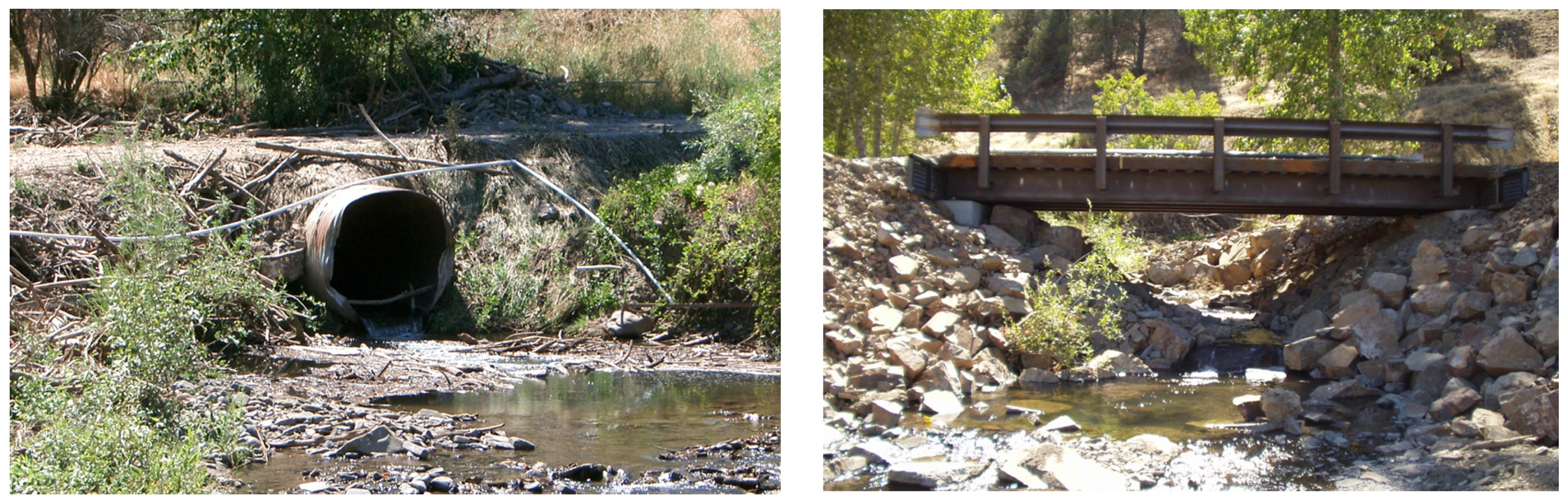
Culvert design historically focused on passing the design flow through the smallest pipe possible, not providing unimpeded transport of sediment, large wood, and aquatic organisms. Single purpose culverts can result in: (1) plugging by large wood or moderate sized organic material; (2) loss of conveyance due to sediment deposition; (3) pressurization of the pipe resulting in the loss of stream bed material from within the pipe; and (4) high exit velocities resulting in downstream channel instability and scour [20,21,22]. Even under moderate flow conditions, a plugged or conveyance compromised culvert may cause flow to overtop the road prism, causing a catastrophic crossing failure. In this circumstance, the failed road fill material is directly delivered to the stream system, potentially impacting downstream habitat. More commonly, bed and bank erosion may develop at the downstream end of a culvert due to flow constriction and a resultant turbulent jet at the culvert outlet [20]. The turbulent jet dislodges particles on the bed and banks of the channel, generally resulting in a deep plunge pool and erosion of the stream banks (Figure 1).
1.1.3. Stream Impacts from Channel Incision
Poorly planned, designed, or implemented culvert replacement or removal projects may inadvertently allow channel incision to progress upstream unmitigated. Without adequate site evaluation and analysis, it is not possible to determine if a culvert is impeding channel incision processes. For example, a common field indicator of an undersized culvert is a wedge-shaped sediment deposit upstream of a culvert. The sediment deposit generally occurs directly upstream (mid-channel) of the culvert, which causes flow deflection around the deposit and erosion of the stream banks and road fill. If this is a localized effect of an undersized culvert, and there is not an arrested headcut at the culvert outlet, it can be corrected with culvert replacement or removal and sediment excavation. In this circumstance, grade control is generally not necessary. However, if the culvert is providing grade control, thus preventing channel incision from progressing upstream, then it is a system-wide effect and it should be anticipated that channel incision will continue to migrate upstream if the structural control is removed [7].
Progression of channel incision is a relatively predictable, although not necessarily linear, process. Changes in the proportionality between the amount and size of sediment, the amount of water, and the stream slope, as described by Lane [15], most often results in either channel incision or aggradation—a vertical response. As an extreme example, channel incision occurs downstream of most dams because bedload is effectively removed from the downstream reach. After channel incision has traversed through a stream reach and the channel bed becomes relatively stable, the enlarged channel contains comparatively greater flows. The subsequent increased shear stress of the deeper, confined flows is translated to the stream banks where erosion can occur. Once the channel has enlarged to such an extent that the near bank shear stress is significantly reduced, the system will start to stabilize, assuming that additional channel incision is not initiated. This “Stream Evolution Model” has been well-documented and is discussed in further detail below [9,23,24].
If system-wide incision has occurred and a culvert is providing grade control, replacement or removal of the culvert may result in the following responses:
- Upstream migrating channel incision and subsequent channel deepening;
- Increased bank height—if critical height is exceeded, bank erosion results;
- Increased sediment supply due to erosion of the channel boundary;
- Disconnection of floodplains from active stream channels;
- Prematurely dewatered or disconnected backwater habitat;
- Locally increased channel slope and loss of pool habitat;
- Drainage of shallow aquifers, thus affecting riparian vegetation, adjacent wetlands, and base flows;
- Increased meander cut-offs due to knickpoint migration across a meander neck caused by an increased elevation drop (head differential) between the old floodplain and active channel bed; and
- Downstream channel aggradation resulting in localized channel braiding.
2. Methods
The main geomorphic consideration for culvert replacement and removal is a rapid, and potentially catastrophic, regrade of the stream channel, including channel bed degradation, lateral erosion, and subsequent deposition of eroded sediment. A vertically unstable stream, either upstream or downstream of a culvert, indicates a high likelihood for channel regrade following culvert replacement. To evaluate the risk for channel regrade, two methodologies that incorporate stream evolution and longitudinal profiles, a Stream Evolution Model (SEM) and Stream Profile Analysis (SPA), are presented. Both methods are widely-used and generally adequate for the purpose of culvert evaluation.
Indicators of stream evolution are the most detectable in systems with cohesive beds and banks (Figure 2), because headcuts remain relatively vertical as they progress upstream, and are thus readily visible. In coarse-bedded rivers, headcuts may be dispersed along several thousand feet of channel and may only be detectable with longitudinal surveys. The SEM [24] is an appropriate tool for reconnaissance level work; however, longitudinal profiles are still required to quantify the actual extent of incision. While the SEM indicates a trend for channel stability, SPA identifies the presence and scale of vertical discontinuity in the streambed. Both inform structure selection used to control stream grade.
2.1. Stream Evolution Model
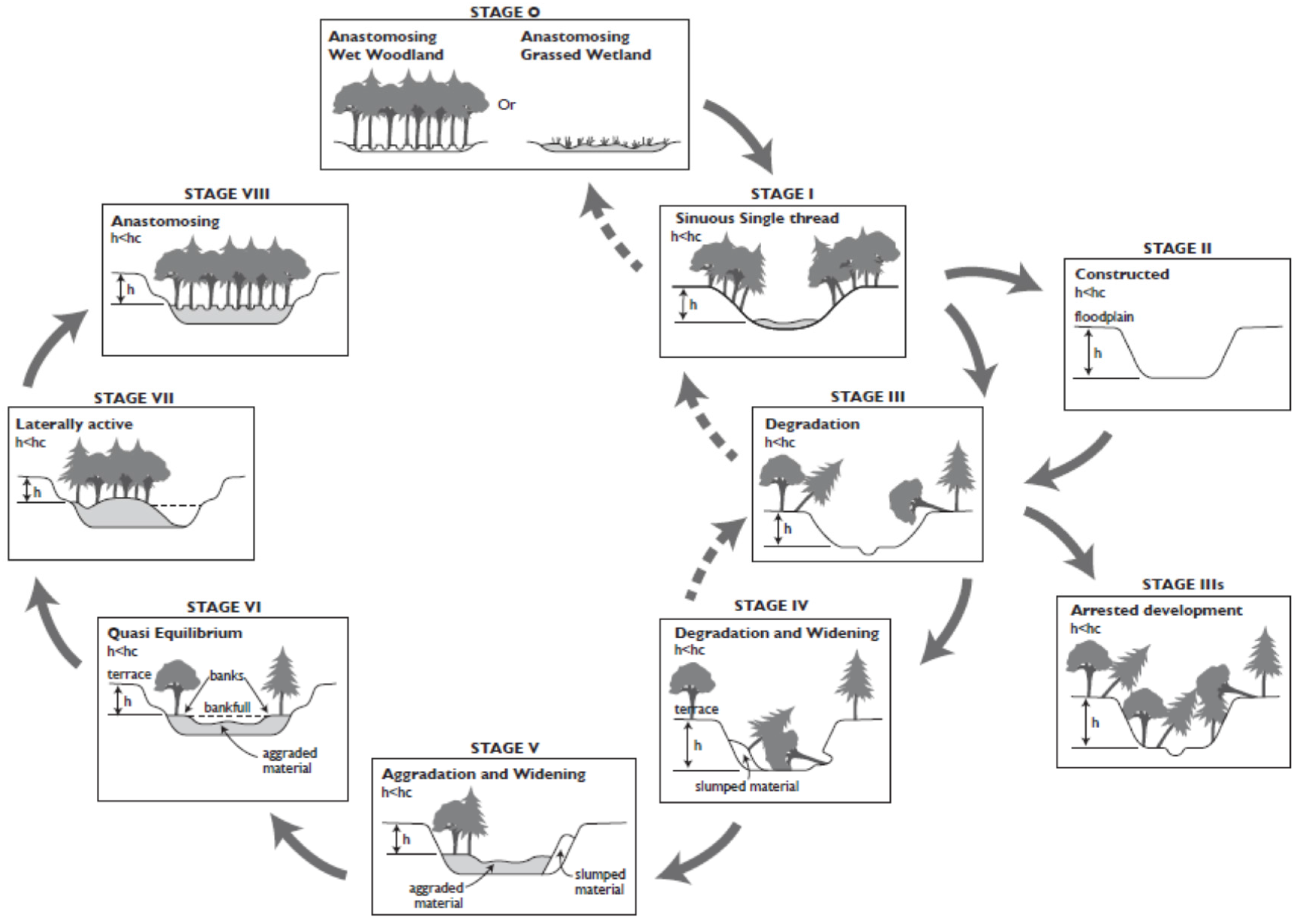
Stream evolution describes progression of a channel through incision, widening, aggradation, and recovery (Figure 3). While the rate and timing of the various stages can vary dramatically, the general trend is well-documented [9,23,24,25]. The use of stream evolution models is only appropriate for alluvial streams that can vertically and/or laterally adjust in engineering time scales.
Determining the stage of stream evolution both above and below a culvert is instrumental in determining the relative vertical stability of a stream reach. Since channel incision is typically followed by channel widening and floodplain development in unconstrained alluvial channels, a difference in the stages of stream evolution above and below a culvert (for example, Stage 1 upstream of a culvert and Stage 5 below the culvert) can indicate that the culvert is functioning as grade control structure, essentially preventing a headcut from migrating upstream. In this case, it may be prudent to add grade control in addition to culvert replacement or removal so that additional channel incision does not occur above the structure.
Numerous channel degradation indicators can be used to detect channel incision, including, but not limited to:
- Headcuts in the stream bed—a vertical drop or off-set in the channel profile;
- Lack of pool habitat in low gradient streams;
- No sediment deposits on the channel bed—scour to bedrock or resistant layer;
- Dead or dying riparian vegetation as a result of dewatering of the shallow groundwater;
- Vertical streambanks on both banks that extend down to the toe of the slope;
- Bank seepage due to dewatering of aquifers;
- Exposed cultural features, such as bridge piers, footings, and aprons, pipelines, or perched culverts; and
- Upland vegetation encroaching into floodplains and riparian areas indicating decreased moisture.
The greater the number of indicators, the greater the likelihood that incision has occurred.
The stage of stream evolution can be determined by investigating the type of erosion that is occurring at a site. If the primary mechanism is erosion of the channel bed, then the channel is at Stage 3. If bank erosion is the primary process, then the channel is at Stage 4. Stage 6 channels exhibit some channel stability and sediment deposition near the banks. It may be difficult to determine whether a stream is at a Stage 1 or 7 if the degree of incision is minimal. It is not uncommon to have a Stage 1 channel above a culvert and a Stage 7 channel below. If the degree of incision is only a few feet, it may be hard to detect, although the impacts of removing the culvert may still occur. This situation requires a longitudinal profile survey to determine the actual degree of channel bed off-set and the stages of stream evolution.
2.2. Stream Profile Analysis
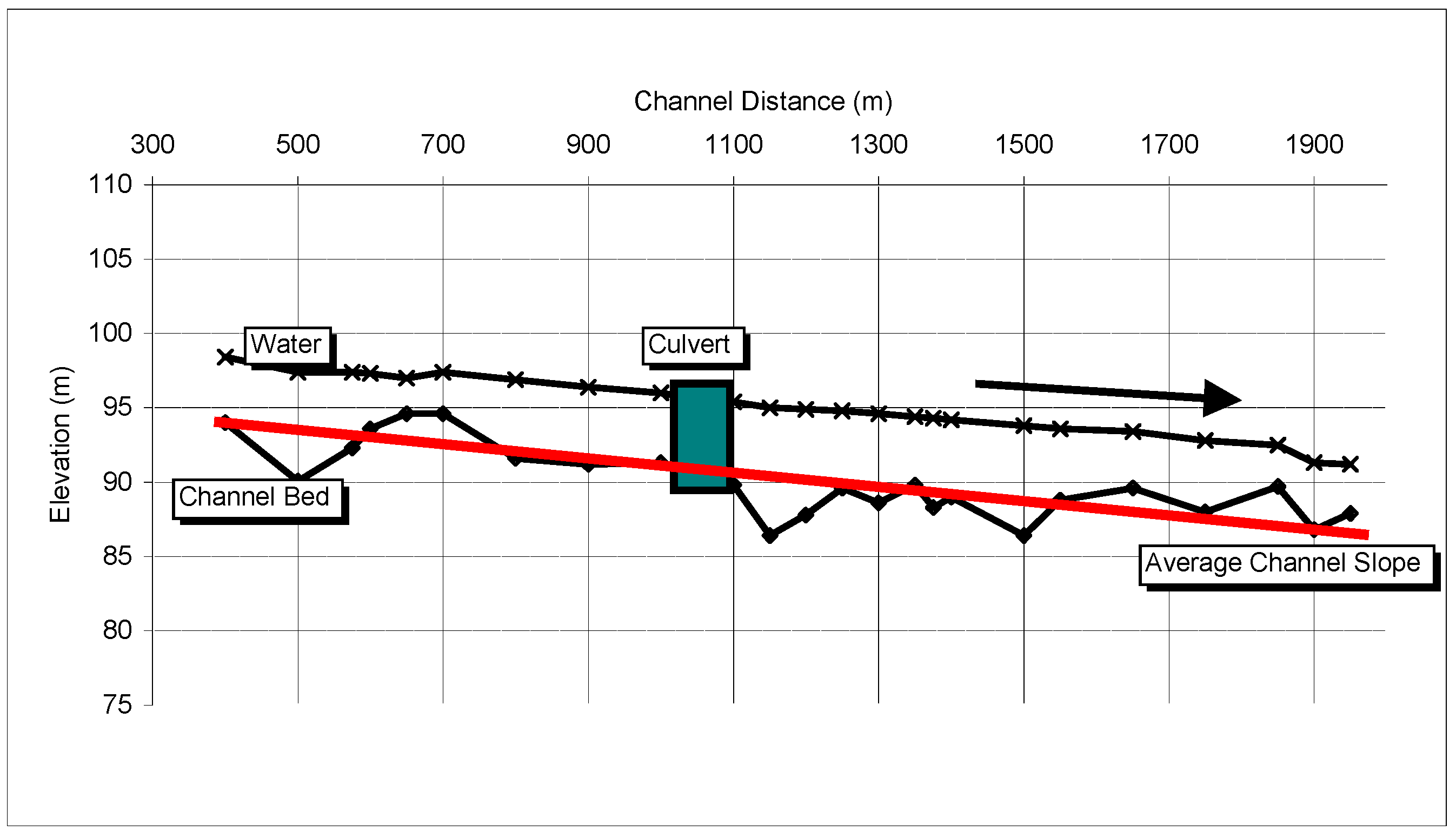
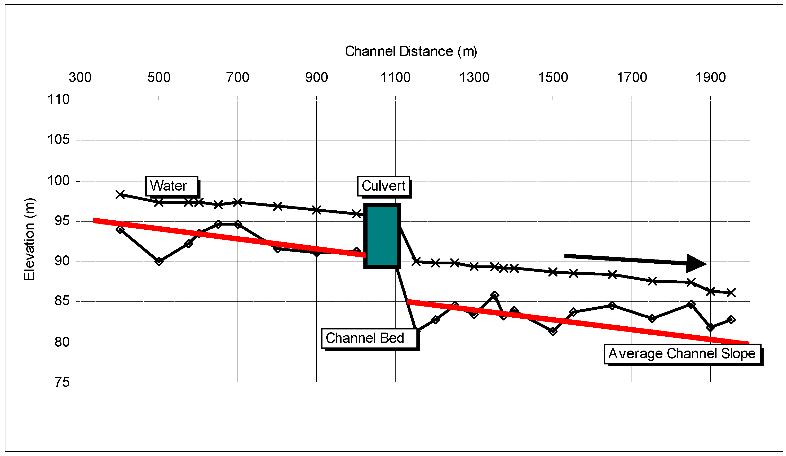
Field reconnaissance and a survey of the longitudinal profile (Figure 4) are conducted as part of the SPA. It is imperative that designers walk the stream prior to the longitudinal survey and make an initial assessment of the required survey length. This should be conducted as part of a field assessment of project reach conditions. During the field assessment, constructed or naturally occurring bed control, such as diversion structures, large wood, or bedrock outcrops, should be noted and their location later identified on the plotted longitudinal profile. These important points should be identified and flagged during the initial assessment, followed by instructions for the survey crew to ensure the points are adequately captured during the topographic survey. When possible, field assessment personnel should also be part of the subsequent survey team. In addition, the survey should extend beyond the area that is directly influenced by the culvert (i.e., the sediment deposit upstream and area of expansion scour downstream, or beyond areas influenced by other structures such as revetments) (Figure 5). Additional survey and assessment details and instructions can be found in Harrelson, et al. [26]. The longitudinal profile is a plot of the thalweg elevation of the stream channel which includes all major bed features. A longitudinal profile can also capture the: (1) current water elevation; (2) channel forming discharge (bankfull) indicators; (3) floodplain elevations; and (4) terrace elevations. Average channel slope can be calculated from a longitudinal profile if the survey is extensive enough.
Longitudinal profiles provide a significant amount of data which informs designs regarding overall stream gradient, habitat unit gradient (pool, riffle, run), habitat unit length and spacing, potential scour depth, depositional areas, profile breaks, headcuts, residual pools, and bed roughness and variation. As a general rule, the surveyed longitudinal profile should extend at least 20 channel widths upstream and downstream of the culvert. However, it may be necessary to increase the length of the survey to capture the presence and magnitude of a potential headcut and to calculate the average channel slopes of the upstream and downstream reaches.
2.3. Post-Project Monitoring
To evaluate the relative success of culvert replacement or removal, documentation of the design process, changes to the design during construction (as-built drawings), and follow-up monitoring are required. In general, photo points are useful for documenting significant changes to the stream, and should be taken from the road surface looking both upstream and downstream. For monitoring, benchmarks and monumented cross-sections should be used for the longitudinal survey. Benchmarks should be located well outside the area of potential stream influence. The survey should include floodplain and terrace elevations to determine if additional channel incision has occurred since project implementation.
2.4. Risk Assessment
Once field reconnaissance and longitudinal surveys are complete, a determination regarding vertical channel stability can be determined using the SEM [24]. If the channel is considered vertically unstable, then a risk assessment should be performed to determine the potential for additional channel erosion and habitat degradation.
We acknowledge that a comprehensive evaluation of channel instability cannot be reliably obtained using standardized methods because each site has unique characteristics. Some critical site variables and project conditions may not be adequately addressed in this section to effectively identify or assess the many channel conditions and response to vertical instability. Additionally, the SEM, SPA, and risk assessment are not a substitute for specific technical expertise to properly evaluate channel instability and develop feasible and sustainable design alternatives.
Determining the degree of channel incision requires a substantial integration of field indicators and professional judgment. A one-foot headcut may be inconsequential for a steep stream with a cobble or boulder bed; however, if the stream is low gradient and sand-bedded, a one-foot headcut may pose a significant threat to channel stability and habitat. Referring back to the potential stream system response to channel incision, the following should be considered:
Upstream headcut migration.
- Will the headcut cause an AOP barrier in the channel or at an upstream structure?
- What is the likelihood that grade control (i.e., bedrock, boulders, or wood) will be encountered and how far is it from the project site?
- Is there other infrastructure, such as upstream road crossings, pipelines, diversions, or communication cables that will be affected?
- Will headcut migration across a meander neck caused by an increased elevation drop between the old floodplain and active channel bed result in a meander cut-off?
High channel banks that may result in mass failure.
- How much bank erosion, both the total area affected and the amount of sediment produced, will likely occur?
- Is bank stabilization necessary due to instream or adjacent structures?
Fine sediment inputs to the stream system.
- Is the stream water quality limited due to fine sediment or contaminated soil?
- What is the caliber of sediment (clay, silt, sand) and will the sediment impact habitat or increase turbidity?
Disconnection of floodplains.
- How often will the abandoned floodplain be inundated—once every 2, 5, 10, 100-years?
- Will increased flow confinement significantly increase stream power within the main channel?
Prematurely dewatered or disconnected backwater habitat.
- Will backwater habitat be completely disconnected or will it be functional for much shorter periods during the year?
- Will disconnection of habitats cause stranding for aquatic species?
Locally increased channel slope and loss of pool habitat.
- Are a lack of pools an aquatic habitat limiting factor?
- Is pool quality, especially residual pool depths, an aquatic habitat limiting factor?
Drainage of shallow aquifers which affects riparian vegetation.
- Can the riparian vegetation survive a drop in the water table commensurate with expected incision?
- Will monitoring of the plant community be used to determine if wetland species are affected by changes in moisture regimes?
Sediment deposition causing localized channel braiding and instability of the streambanks.
- Is deposition of coarse sediment en masse likely?
- Will mid-channel bar formation cause concentrated flow near stream banks?
- Is local aggradation causing a shallow, wide channel a concern for AOP?
Site-specific impacts due to headcut migration beyond those listed above are likely. While it is not necessary to quantify all processes, they should be at least qualitatively evaluated for a risk assessment.
3. Applications
It is not possible to describe all of the various scenarios for culvert replacement or removal because each site is unique and requires an individual assessment as discussed above. There are however, general characteristics of preferred treatments that may be favorable across many different stream systems, for a wide variety of species and life histories. The most appropriate treatment for channel incision is one that integrates with the geomorphology of the adjacent stream reach. Geomorphic approaches to road/stream crossing design use measurable characteristics of reference channels as standards for reproducing, simulating, or informing the design of the project channel. The degree to which the hydraulic and geomorphic diversity of the road/stream crossing simulates the adjacent, or morphologically similar stream reaches, determines the degree of AOP provided through the crossing. Correspondingly, the degree to which reference geomorphic conditions can or will be exhibited in the design determines the type of geomorphic approach used.
3.1. Geomorphic Approaches
For the purposes of AOP, the design channel slope and floodplain characteristics should be as similar as possible to the adjacent channel and floodplain given project constraints. Three geomorphic approaches are commonly used to accomplish this: (1) full restoration of the floodplain and channel; (2) stream simulation; and (3) morphologic simulation.
Removal of the road crossing and fully restoring the floodplain and channel is the preferred method for providing maximum AOP. This approach completely restores geomorphic form and function, as well as all fluvial processes of the crossing channel and its adjacent floodplain. Due to economic, social, and/or spatial considerations or limitations, crossing removal and full restoration is often not a feasible option.
A second option, “stream simulation design” (SSD), differs from full channel and floodplain restoration in that it restores some, but not all, floodplain processes and functions. SSD is a specific geomorphic approach with reasonably consistent design guidance [6,10,27]. Hallmarks of SSD include: (1) crossing spans dictated by bankfull channel width; (2) minimal allowable deviation from adjacent stream slopes; (3) streambed design that mimics reference reach bed material particle size, composition, and roughness; and (4) allowance for vertical channel adjustment through the crossing. Data used to construct a SSD are obtained by measuring geomorphic characteristics from a reference reach, which are then used to mimic, or simulate, the reference reach channel within the road/stream crossing. There is little reliance on traditional hydraulic engineering methods. SSD holds the assumption that if the stream channel of a road/stream crossing can be constructed to sustain similar geometric, geomorphic, and hydraulic conditions of the reference channel, no additional unnatural barriers to passage are created through the crossing [6]. This concept has been developed and applied successfully in stable steep coarse alluvial channels of both confined and moderately confined morphologies [8]. SSD may have further limitations to its applicability when: (1) the project slope becomes too dissimilar to the upstream or downstream channel; (2) bankfull indicators are absent, conflicting or non-diagnostic; (3) sediment transport is degraded or fragmented through the project reach; or (4) where existing channel hydraulics do not represent reference conditions. Where SSD is not attainable, other geomorphic approaches may still be appropriate for providing AOP.
When extensive grade control is required, full restoration and stream simulation are not appropriate design methods. In this case, “morphologic simulation” is applied to grade control and threshold channel design, which results in geomorphological forms that may be found within the watershed, but are not necessarily present within the project reach. For steeper grade control channels, AOP can only be reliably achieved by constructing a channel that mimics the diversity and complexity found in the roughness, flow velocities, and hydraulic conditions of higher gradient channel morphologies. This approach may provide adequate migration paths and resting areas for a variety of aquatic species [28,29]. Data used to inform morphologic grade control structures are obtained by: (1) measuring geomorphic characteristics from reference reaches; (2) incorporating general and regionally derived geomorphic relationships into the design; and (3) conducting engineering analysis to evaluate stability and hydraulic conditions of proposed morphology. The design process is iterative with feedback loops refining the design geometry, spacing, and roughness to provide morphology supporting AOP and structural integrity of the constructed channel. Engineering guidance has been applied to the design of morphologic simulations with varying degrees of success [8,10,30,31,32,33,34].
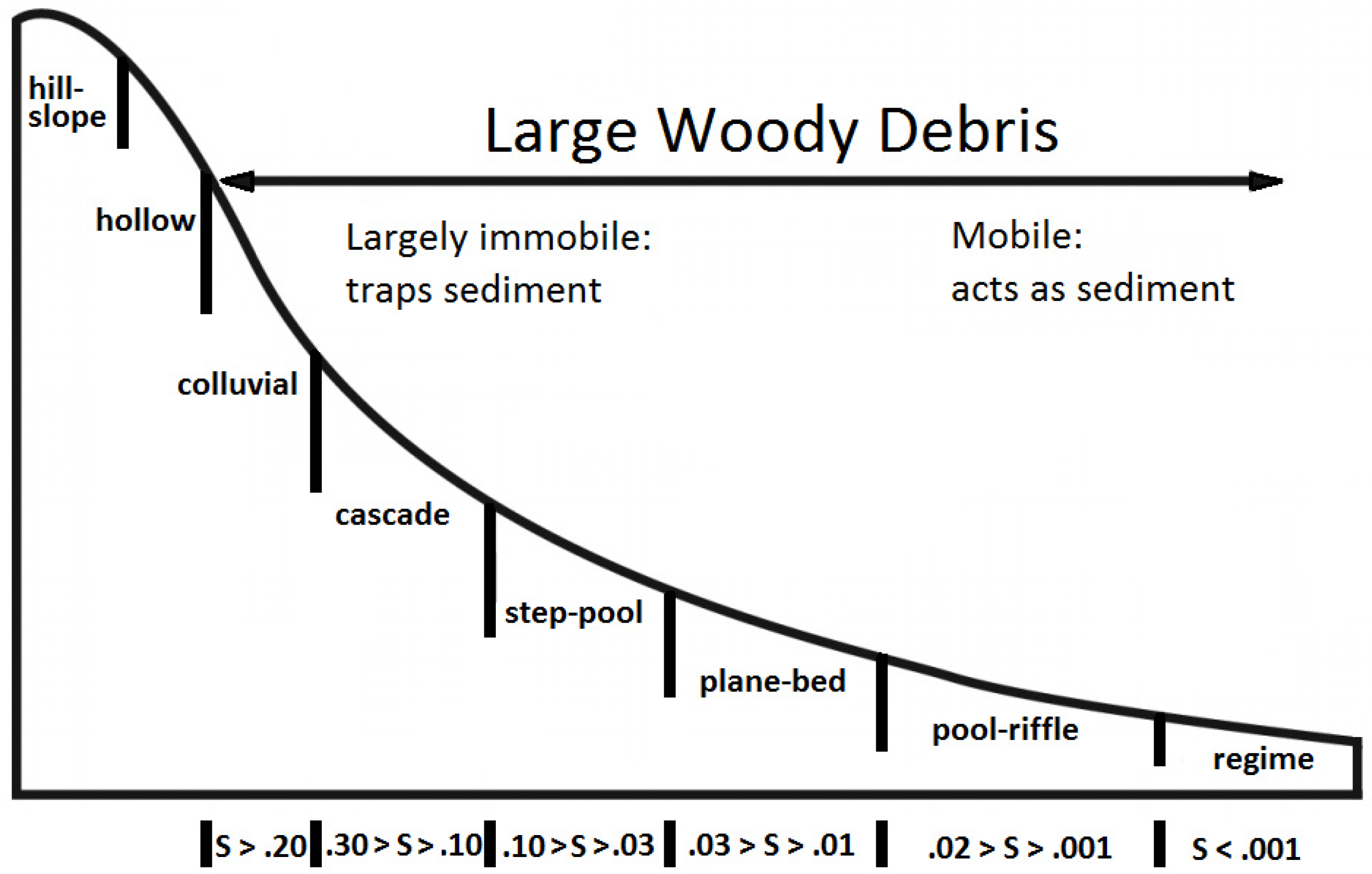
3.2. Grade Control Treatments
We have stratified grade control treatments into broad slope categories based on Montgomery and Buffington’s [35] stream types of pool-riffle, step-pool, cascade, and colluvial (Figure 7). Ideally, channel reconstruction and grade control activities remain within the same geomorphic class as adjacent stream reaches; however, it is acceptable to move the stream into a steeper adjacent category if there has been a significant channel bed off-set, especially for channels that are near the upper limits of channel slope defined by Montgomery and Buffington [36]. For example, to “reconnect” the channel profile, a pool-riffle stream reach with a 1% average reach slope may incorporate a structure that simulates a rougher, steeper pool-riffle morphology that is up to an average reach slope of 2% to 3%, depending on project or site-specific factors. If additional slope is required to reconnect the channel, a step-pool or cascade-type morphology may be preferred; however, using a significantly higher gradient design than the adjacent reach may represent a magnitude of change in hydraulic conditions leading to an unacceptable delay or loss of passage for some species. Significant floodplain and slope discontinuities may also be too drastic for engineering methods to sustain both the anticipated passage conditions and structural stability for the life of the structure.
We have not included plane bed stream types because they are transitional between pool-riffle and step-pool [36] and may not represent a stable channel form over time. Plane bed morphologies are also characterized by featureless channels lacking depositional forms [37] which typically lack the morphologic and hydraulic diversity that are critical to AOP. Similarly, we have not included regime stream types because of their lack of structure, and hence structural analogues.
Grade control treatment alternatives include, but are not limited to: (1) do nothing; (2) large roughness elements; (3) constructed riffles; (4) constructed steps; and (5) constructed cascades. The choice of treatment is based on site conditions (i.e., channel slope or bed material type), material availability, economics, land use, design competence or familiarity, regulatory restrictions (i.e., jump heights and stream velocity for fish), and benefits and limitations (Table 2).
3.2.1. The “Do Nothing” Alternative
If the evaluation of the stage of stream evolution and SPA indicate a low risk for channel incision (i.e., minimal headcut relative to channel size or evidence of natural grade control such as bedrock, cemented gravel, or buried wood), and downstream riparian and channel conditions are adequate, then a “no-action” alternative may be indicated. In this circumstance, the culvert would be replaced or removed without the addition of grade control.
Determining the significance of a headcut is site-specific and requires the judgment of a geomorphologist or other trained professional. An evaluation of downstream channel resilience (i.e., the existence of floodplains, stable banks, and well vegetated riparian zones) is essential because this area will be impacted by the additional sediment generated from channel erosion.
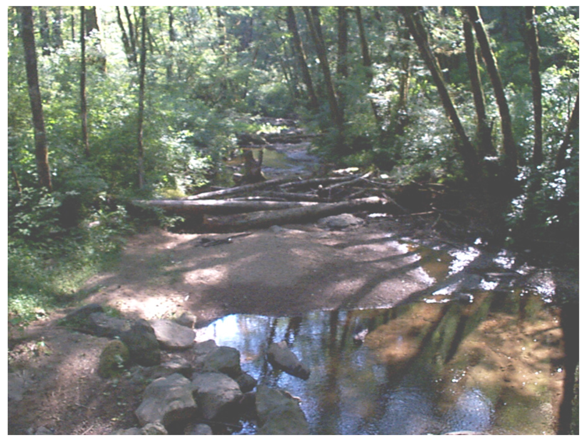
3.2.2. Large Roughness Elements: Wood and Boulders
In many streams, large wood and boulders provide natural grade control in the form of channel spanning log jams, debris flow deposits, or landslide deposits. It is often feasible to mimic this natural analogue to provide grade stabilization in areas where the risk of headcut migration exists (Figure 8). The goal of using large roughness elements is not to completely halt the incision process, but rather to spread the elevation change over a greater length of channel and a longer span of time.
Since log jams are porous structures, not all of the sediment will be held in place; however, sediment inputs will be meted out over time rather than introduced to the stream as one large pulse. An engineered large wood structure may be self-maintaining as long as additional large wood is available within the reach or from upstream sources.
To hold existing sediment in place above a culvert, large wood should be buried into the stream bottom and should be relatively channel-spanning. Boulders can be used as anchor points or to increase structure mass to reduce buoyancy. As with any structural approach, risk can be dispersed through redundancy. Several smaller structures can be relied upon, rather than a single large structure. Large wood structures placed downstream of a road crossing may include an anchoring system, but do not necessarily need to be buried in the channel bed. The downstream large wood will retain some sediment as it moves through the reach.
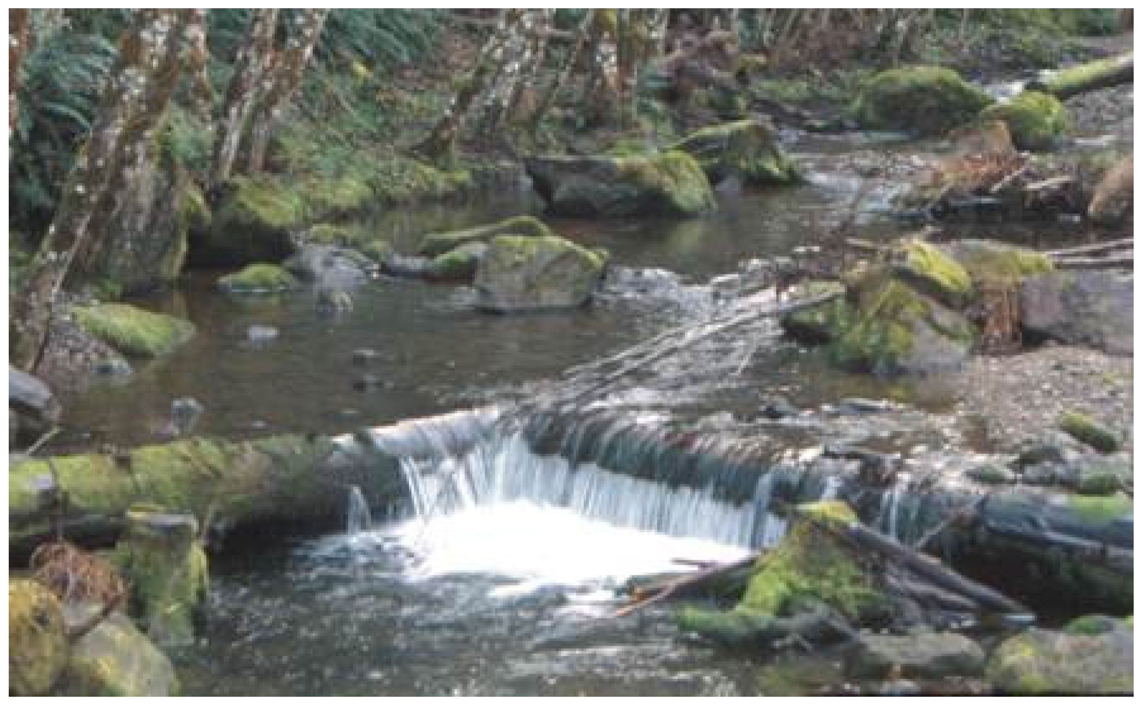
3.2.3. Constructed Riffles
Constructed riffles were initially derived from rock weirs which were subsequently buried with smaller material to create gradually-varied, rather than rapidly-varied, flow to reduce the jump height for fish and to reduce the likelihood of failure due to undercutting (Figure 9). The concept of constructed riffles is often attributed to Bob Newbury and his “Newbury riffles”, which have been implemented in projects across North America [33].
3.2.4. Constructed Steps
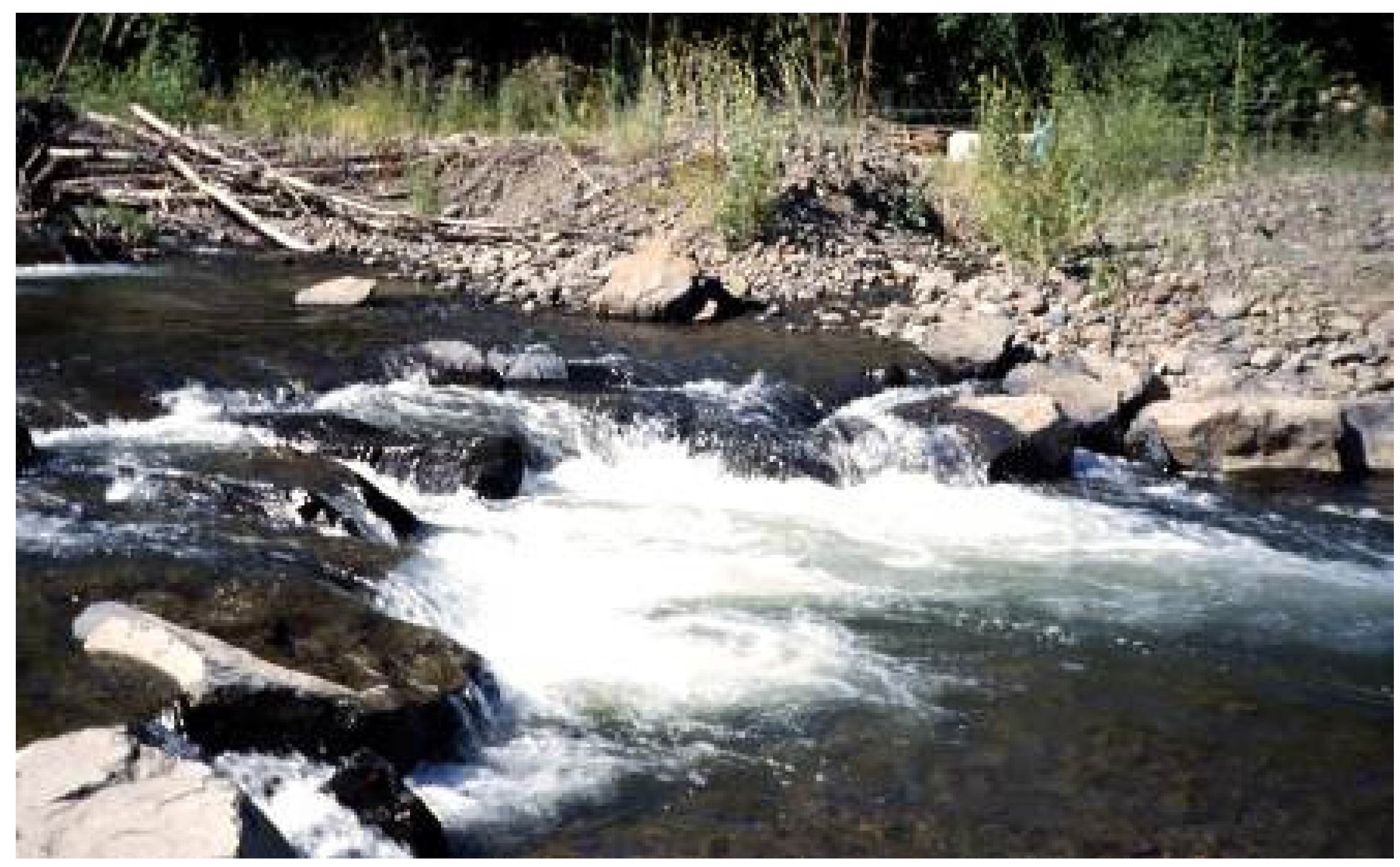
Rock and log weirs (Figure 10 and Figure 11) are commonly used to stabilize channel beds. Straight weirs disperse flows and can cause channel widening and thus structure flanking (erosion around the ends of the structure). To minimize this effect, “V” shaped weirs that are oriented with the apex upstream and are lower in the center were developed. Since water crosses perpendicular to the weir face, the “V” shape redirects flow back to the center of the channel.
Because of high failure rates of rock and log weir structures [38,39], some engineers have begun moving away from grade control structures that produce extensive or prolonged plunging flow conditions, and do not provide sufficient structural redundancy in the design. Typical boulder weir designs [40] use two or three rows of similarly sized “footer” and “header” rock to span the channel, which makes them highly susceptible to future porosity issues, such as piping and subsurface flow. The structural rock is oriented in the vertical plane to produce a well-developed plunging jet.
The spacing and vertical displacement of individual weirs is often developed along strict state and federal fish passage criteria regarding allowable jump height. These constraints produce a structure that is much more hydraulic, rather than morphologic, in form and function, which may cause weirs to be impractical in steeper streams or in areas where the right-of-way is limited and there is no access to adjacent property. If weirs must be placed close together, the jet from one weir impinges on the next downstream weir, tending to undermine or wash it out, and the weir system becomes a turbulent chute which could become a passage barrier.
Due to the random entrainment and configuration of steps in natural step-pool morphologies, they generally contain flow paths that allow species to swim through the structure. Natural steps often resemble very short and steep rough chutes, not discrete vertical drops with extremely well defined vertical jets as is common in many engineered designs, contain a gradation that promotes surface flow, possess scour resistant pools and banks, and exhibit structural redundancy in the increased presence and distribution of large rock both within and local to natural steps. [35]. Designing steps to these conditions can increase the passage window, as well as facilitate passage of a wider range of species. All of these attributes should be incorporated into the design of step-pool systems. With regard to AOP we believe that structures which produce streaming flow via a short chute, versus plunging flow via a vertical drop, is more desirable to pass a wider range of species. Current modifications to traditional boulder weir designs include constructing armored pools and banks downstream of the weirs, or steps, using reference step-pool spacing to determine appropriate placement, increasing the well-graded characteristic of step material, and using a minimum of three to four “header” and “footer” rocks to develop a short rough chute versus a discrete drop (Figure 12).
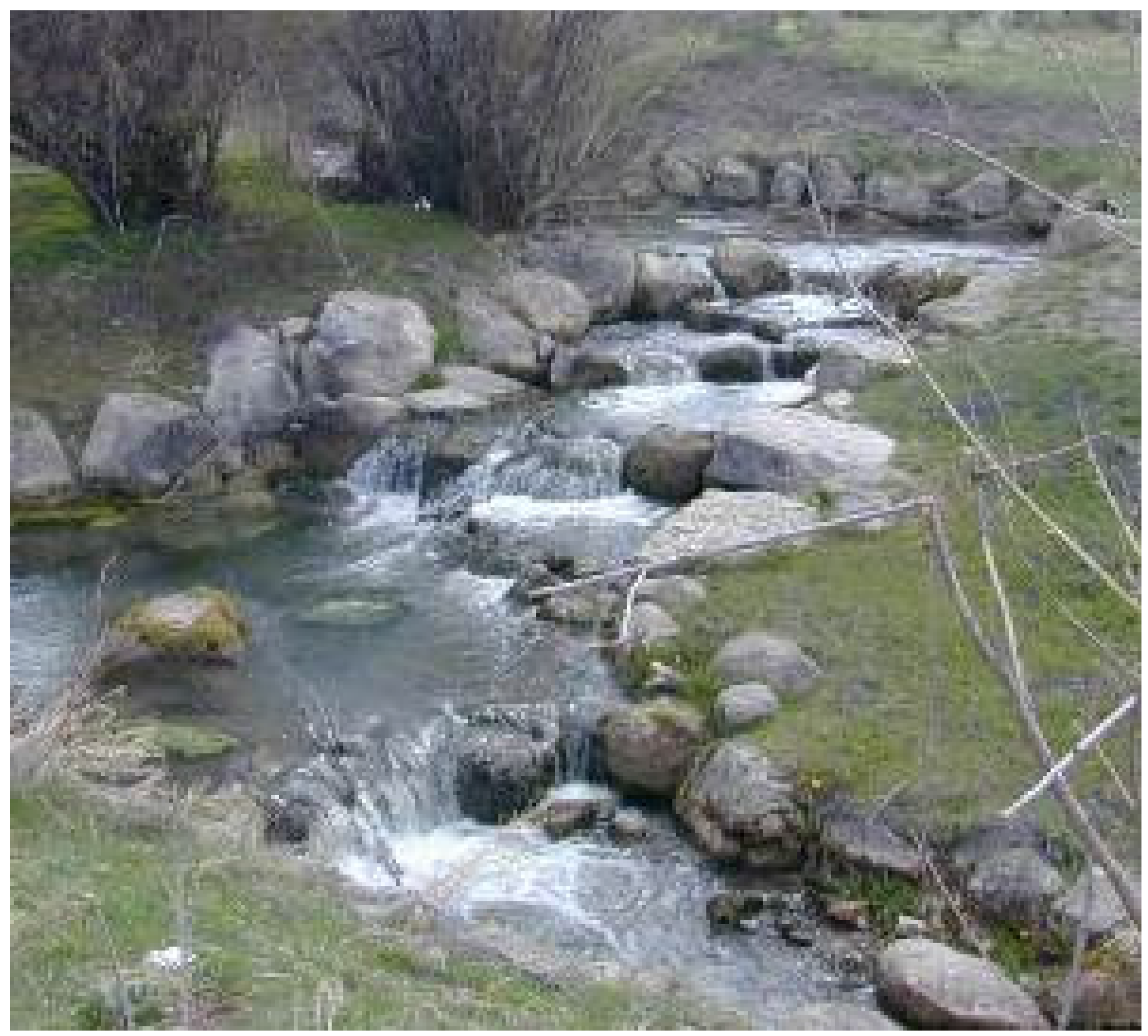
3.2.5. Constructed Cascades
Constructed cascades, which mimic steep (>10%) cascade stream types, are often referred to as “roughened channels” or “roughened chutes” (Figure 13) [35]. Although these stream types are often out of geomorphic context for a given stream reach, they still rely on natural channel processes to pass water, sediment, wood, and aquatic organisms, although passage will likely be impaired for many species. Cascades are most appropriate in stream reaches that are steep, very coarse bedded, or in areas where the work area is restricted due to rights-of-way or other constraints; they may also be preferable in areas where banks are high and excavation is considerable. Cascades are designed without drops, but as discrete steep rough chutes. Chute roughness and pool size and spacing between individual chutes are used to dissipate energy and provide passable conditions. Based on the size and distribution of large material within individual chutes, resting and holding areas can be provided for many species. Attention should be given to the relative roughness and orientation of banks where smaller, weaker aquatic species are a concern. These species will likely use channel margins for passage, especially if turbulence and velocity can be further reduced, or holding areas maximized, along the margins through design.
A “culvert confined cascade” has been designed and implemented in the PNW, which is a variation of the constructed cascade approach. The culvert is placed at a relatively steep angle, connecting the upstream and downstream stable bed elevations. The headcut is basically incorporated into the length of the culvert. This approach may be applicable in areas with a minimal perch height on relatively low gradient streams. Rock is required within the culvert to provide bed roughness to allow for fish passage. For steeper slopes and higher perches, a culvert confined cascade will likely be a fish passage barrier, especially for juveniles. Rock within the culvert could trap debris and cause chronic maintenance issues or risk of failure. Several sources provide well-developed techniques for this type of design termed a “roughened channel” [10,27,29]. Its application is limited based on the gradient and sediment transport characteristics of the channel. The method has been used for both in-culvert and out-of-culvert applications.
4. Conclusions
A considerable amount of time, energy, and money is spent replacing or removing culverts that are barriers to aquatic organisms, and especially fish. Because of the magnitude of effects, it is critical that a geomorphological evaluation of the site be completed to determine potential impacts both at the site and along the stream reach. Vertical instability can result in a suite of negative impacts that range from loss of backwater habitat to increased levels of turbidity. An evaluation of the risks to channel morphology, habitat, and infrastructure should be performed before any decision is made regarding culvert removal or replacement. By utilizing the Stream Evolution Model and Stream Profile Analysis, the risk can be quantified, or at least described in terms of potential impacts, which is an important tool for managers that oversee stream related projects. These risks will determine whether grade control structures are necessary, while the stream type will provide an analogue for structure selection.
Acknowledgments
The development of this manuscript was supported solely by the authors’ employers, the United States Fish and Wildlife Service, Oregon Fish and Wildlife Office, and the National Oceanic and Atmospheric Administration, National Marine Fisheries Service, Portland Oregon Office.
Author Contributions
The original US Fish and Wildlife Service unpublished manuscript that was the impetus for this paper was authored by Janine Castro as part of her job duties in 2003. Aaron Beavers provided additional engineering and fish passage components to the current manuscript, including the introduction of the term “Stream Profile Analysis” and the entire discussion on Stream Simulation Design. Much of the material presented is derived from professional experience and hence has no reference.
Conflicts of Interest
The authors declare no conflict of interest.
References
- Nehlsen, W.; Williams, J.E.; Lichatowich, J.A. Pacific salmon at the crossroads: Stocks at Risk from California, Oregon, Idaho, and Washington. Fisheries 1991, 16, 4–21. [Google Scholar] [CrossRef]
- Forman, R.T.; Alexander, L.E. Roads and their major ecological effects. Annu. Rev. Ecol. Syst. 1998, 29, 207–231. [Google Scholar] [CrossRef]
- Hoffman, R.L.; Dunham, J.B.; Hansen, B.P. Aquatic Organism Passage at Road-Stream Crossings—Synthesis and Guidelines for Effectiveness Monitoring; Open-File Report 2012–1090; U.S. Geological Survey: VA, USA, 2012.
- Mallen-Cooper, M.; Brand, D.A. Non-salmonids in a salmonid fishway: What do 50 years of data tell us about past and future fish passage? Fish. Manag. Ecol. 2007, 14, 319–332. [Google Scholar] [CrossRef]
- Noonan, M.J.; Grant, J.W.A.; Jackson, C.D. A quantitative assessment of fish passage efficiency. Fish Fish. 2012, 13, 450–464. [Google Scholar] [CrossRef]
- United States Forest Service (USFS). Stream Simulation: An Ecological Approach to Providing Passage for Aquatic Organisms at Road-Stream Crossings; National Technology and Development Program; U.S. Department of Agriculture, Forest Service National Technology and Development Program: San Dimas, CA, USA, 2008.
- Castro, J. Geomorphologic Impacts of Culvert Replacement and Removal: Avoiding Channel Incision; Unpublished Report; US Fish and Wildlife Service: Portland, OR, USA, 2003.
- Barnard, R.J.; Yokers, S.; Nagygyor, A.; Quinn, T. An evaluation of the stream simulation culvert design method in Washington State. River Res. Appl. 2014, 31, 1376–1387. [Google Scholar] [CrossRef]
- Schumm, S.A.; Harvey, M.; Watson, C. Incised Channels: Morphology, Dynamics, and Control; Water Resources Publications: Littleton, CO, USA, 1984. [Google Scholar]
- Love, M.; Bates, K. Part XII: Fish passage design and implementation. In California Salmonid Stream Habitat Restoration Manual; California Department of Fish and Wildlife: Sacramento, CA, USA, 2009; p. 188. [Google Scholar]
- Booth, D.B. Urbanization and the natural drainage system—Impacts, solutions, and prognoses. Northwest Environ. J. 1991, 7, 93–118. [Google Scholar]
- Galay, V.J. Causes of river bed degradation. Water Resour. Res. 1983, 19, 1057–1090. [Google Scholar] [CrossRef]
- Skidmore, P.B.; Thorne, C.R.; Cluer, B.L.; Pess, G.R.; Castro, J.M.; Beechie, T.J.; Shea, C.C. Science Base and Tools for Evaluating Stream Engineering, Management, and Restoration Proposals; NOAA Tech Memo, NMFS-NWFSC-112; U.S. Department of Commerce: Wahington, DC, USA, 2011; p. 255.
- Jones, J.A.; Swanson, F.J.; Wemple, B.C.; Snyder, K.U. Effects of roads on hydrology, geomorphology, and disturbance patches in stream networks. Conserv. Biol. 2000, 14, 76–85. [Google Scholar] [CrossRef]
- Lane, E.W. Design of stable alluvial channels. Trans. Am. Soc. Civ. Eng. 1955, 120, 1234–1260. [Google Scholar]
- Rosenberg, D.K.; Noon, B.R.; Meslow, E.C. Biological corridors: Form, function, and efficacy. Bioscience 1997, 47, 677–687. [Google Scholar] [CrossRef]
- Lang, M.; Love, M.; Trush, W. Improving Fish Passage at Road Crossings; Final Report to the National Marine Fisheries Service, Produced in Cooperation with Humboldt State University Foundation under NMFS; Contract 50ABNF800082; NMFS: Arcata, CA, USA, 2004; p. 128.
- Mooney, D.M.; Holmquist-Johnson, C.L.; Holurn, E. Qualitative Evaluation of Rock Weir Field Performance and Failure Mechanisms; U.S. Department of the Interior, Bureau of Reclamation, Sedimentation and River Hydraulics Group, Technical Service Center: Denver, CO, USA, 2007.
- Price, D.M.; Quinn, T.; Barnard, T.J. Fish passage effectiveness of recently constructed road crossing culverts in the Puget Sound region of Washington state. N. Am. J. Fish. Manag. 2010, 30, 1110–1125. [Google Scholar] [CrossRef]
- Furniss, M.J.; Ledwith, T.S.; Love, M.A.; McFadin, B.A.; Flanagan, S.A. Response of Road-Stream Crossings to Large Flood Events in Washington, Oregon, and Northern California; 9877 1806-SDTDC; U.S. Forest Service: San Dimas, CA, USA, 1998.
- Tsihrintzis, V. Effects of sediment on drainage-culvert serviceability. J. Perform. Constr. Facil. 1995, 9, 172–183. [Google Scholar] [CrossRef]
- Thompson, P.; Kilgore, R. Hydraulic design of energy dissipators for culverts and channels. In Hydraulic Engineering Circular No. 14, 3rd ed.Federal Highways Administration, National Highway Institute: Washington, DC, USA, 2006. [Google Scholar]
- Simon, A.; Rinaldi, M. Channel instability in the loess area of the Midwestern United States. J. Am. Water Resour. Assoc. 2000, 36, 133–150. [Google Scholar] [CrossRef]
- Cluer, B.; Thorne, C.R. A stream evolution model integrating habitat and ecosystem benefits. River Res. Appl. 2014, 30, 135–154. [Google Scholar] [CrossRef]
- Simon, A.; Hupp, C.R. Channel evolution in modified Tennessee channels. In Proceedings of the Fourth Federal Interagency Sedimentation Conference, Las Vegas, NV, USA, 24–27 March 1986; Volume 2.
- Harrelson, C.C.; Rawlins, C.L.; Potyondy, J.P. Stream Channel Reference Sites: An Illustrated Guide to Field Technique; General Technical Report RM-245; U.S. Department of Agriculture, Forest Service, Rocky Mountain Forest and Range Experiment Station: Fort Collins, CO, USA, 1994.
- Barnard, R.J.; Johnson, J.; Brooks, P.; Bates, K.M.; Heiner, B.; Klavas, J.P.; Ponder, D.C.; Smith, P.D.; Powers, P.D. Water Crossings Design Guidelines; Washington Department of Fish and Wildlife: Olympia, DC, USA, 2013.
- Thorncraft, G.A.; Harris, J.H. Assessment of Rock-Ramp Fishways; NSW Fisheries Research Institute and the Cooperative Research Center for Freshwater Ecology: Pyrmont, Australia, 1996. [Google Scholar]
- Bates, K. Design of Culverts for Fish Passage; Washington Department of Fish and Wildlife: Olympia, Washington, DC, USA, 2003.
- Mooney, D.M.; Holmquist-Johnson, C.L.; Broderick, S. Rock Ramp Design Guidelines; U.S. Department of the Interior Bureau of Reclamation, Sedimentation and River Hydraulics Group, Technical Service Center: Denver, CO, USA, 2007.
- Lorenz, E.A.; Lobrecht, M.N.; Robinson, K.M. An excel program to design rock chutes for grade stabilization. In Proceedings of the ASAE Annual International Meeting, Milwaukee, WI, USA, 9–12 July 2000; pp. 1–22.
- Keller, R.J. Guidelines for the Design of Rock Chutes Using CHUTE; Cooperative Research Centre for Catchment Hydrology: Melbourne, Australia, 2003. [Google Scholar]
- Newbury, R.W.; Gaboury, M.N. Stream Analysis and Fish Habitat Design; A Field Manual; Newbury Hydraulics: Gibsons, BC, Canada, 1993; p. 256. [Google Scholar]
- Newbury, R.N.; Gaboury, M.N.; Bates, D. Restoring habitats in channelized or uniform streams using riffle and pool sequences. In Fish Habitat Rehabilitation Procedures; Watershed Restoration Technical Circular; Slaney, P.A., Zaldokas, D., Eds.; Ministry of Environment, Lands and Parks, and Ministry of Forests: Vancouver, BC, Canada, 1997; Volume 9, Chapter 12; p. 341. [Google Scholar]
- Montgomery, D.R.; Buffington, J.M. Channel Classification, Prediction of Channel Response, and Assessment of Channel Condition: Olympia, Washington; Washington State Department of Natural Resources Report; TFW-SH10-93-002; Washington State Department of Natural Resources: Olympia, DC, USA, 1993; p. 86.
- Montgomery, D.R.; Buffington, J.M. Channel-reach morphology in mountain drainage basins. Geol. Soc. Am. Bull. 1997, 109, 591–611. [Google Scholar] [CrossRef]
- Montgomery, D.R.; Buffington, J.M. Channel processes, classification, and response. In River Ecology and Management: Lessons from the Pacific Coastal Region, 1st ed.; Naiman, R.J., Bilby, R.E., Kantor, S., Eds.; Springer: New York, NY, USA, 1998; pp. 13–42. [Google Scholar]
- Frissell, C.; Nawa, R. Incidence and causes of physical failure of artificial habitat structures in streams of western Oregon and Washington. N. Am. J. Fish. Manag. 1992, 12, 182–197. [Google Scholar] [CrossRef]
- Holburn, E.; Varyu, D.; Russell, K. Quantitative Investigation of the Field Performance of Rock Weirs; U.S. Department of the Interior Bureau of Reclamation Technical Service Center: Denver, CO, USA, 2009.
- Rosgen, D.L. The cross-vane, w-weir and j-hook vane structures...their description, design and application for stream stabilization and river restoration. In Proceedings of the 2001 Wetlands Engineering & River Restoration Conference, Reno, NV, USA, 27–31 August 2001.
Figure 1.
Original undersized culvert and subsequent bridge replacement.

Figure 2.
Example stream evolution from South Dakota (see Figure 3 for stream stage description) (photos courtesy of Lyle Steffen).
Figure 2.
Example stream evolution from South Dakota (see Figure 3 for stream stage description) (photos courtesy of Lyle Steffen).
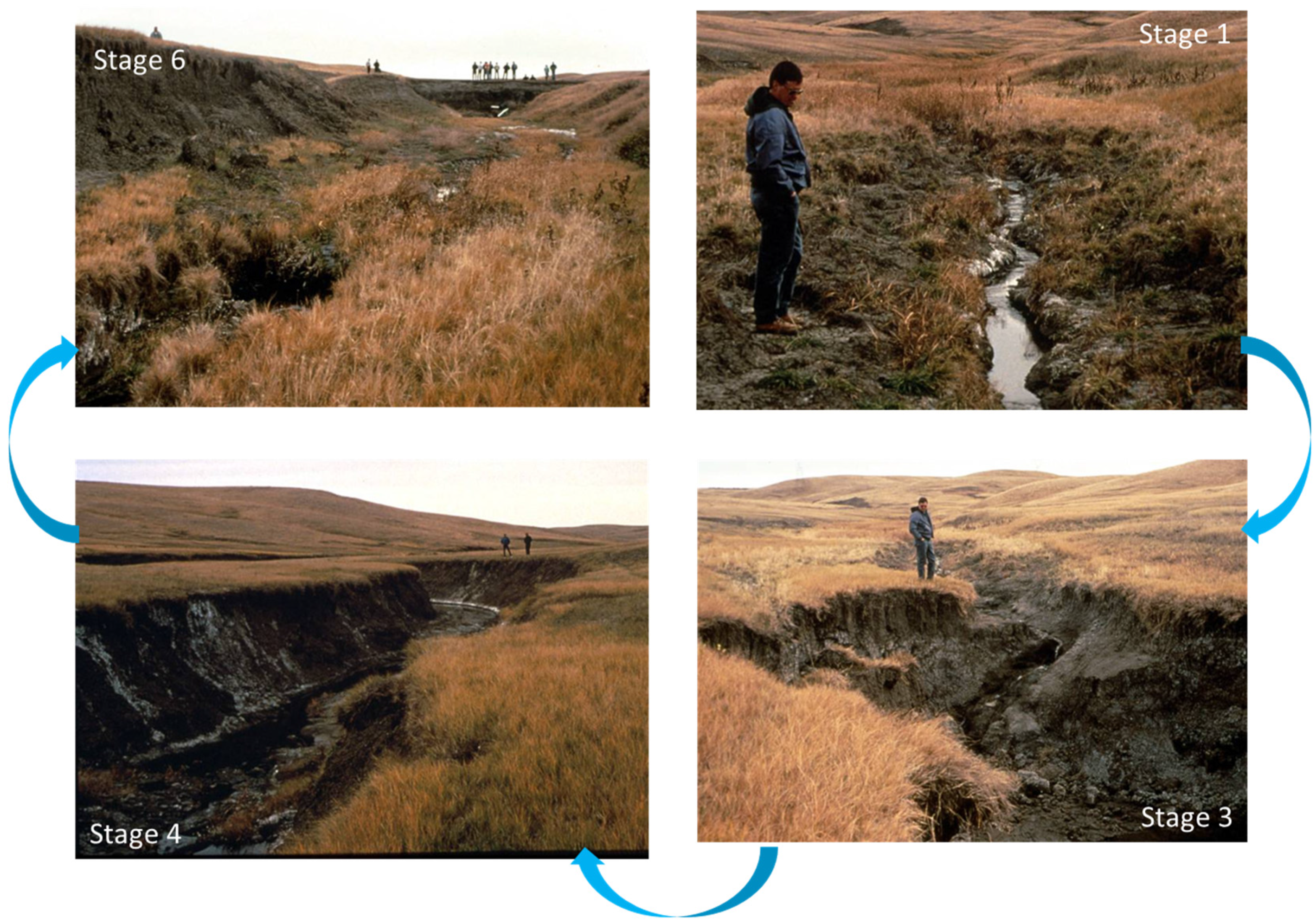
Figure 3.
Stream Evolution Model from: Cluer and Thorne [24].
Figure 3.
Stream Evolution Model from: Cluer and Thorne [24].

Figure 4.
Example longitudinal profile with no channel bed off-set.

Figure 5.
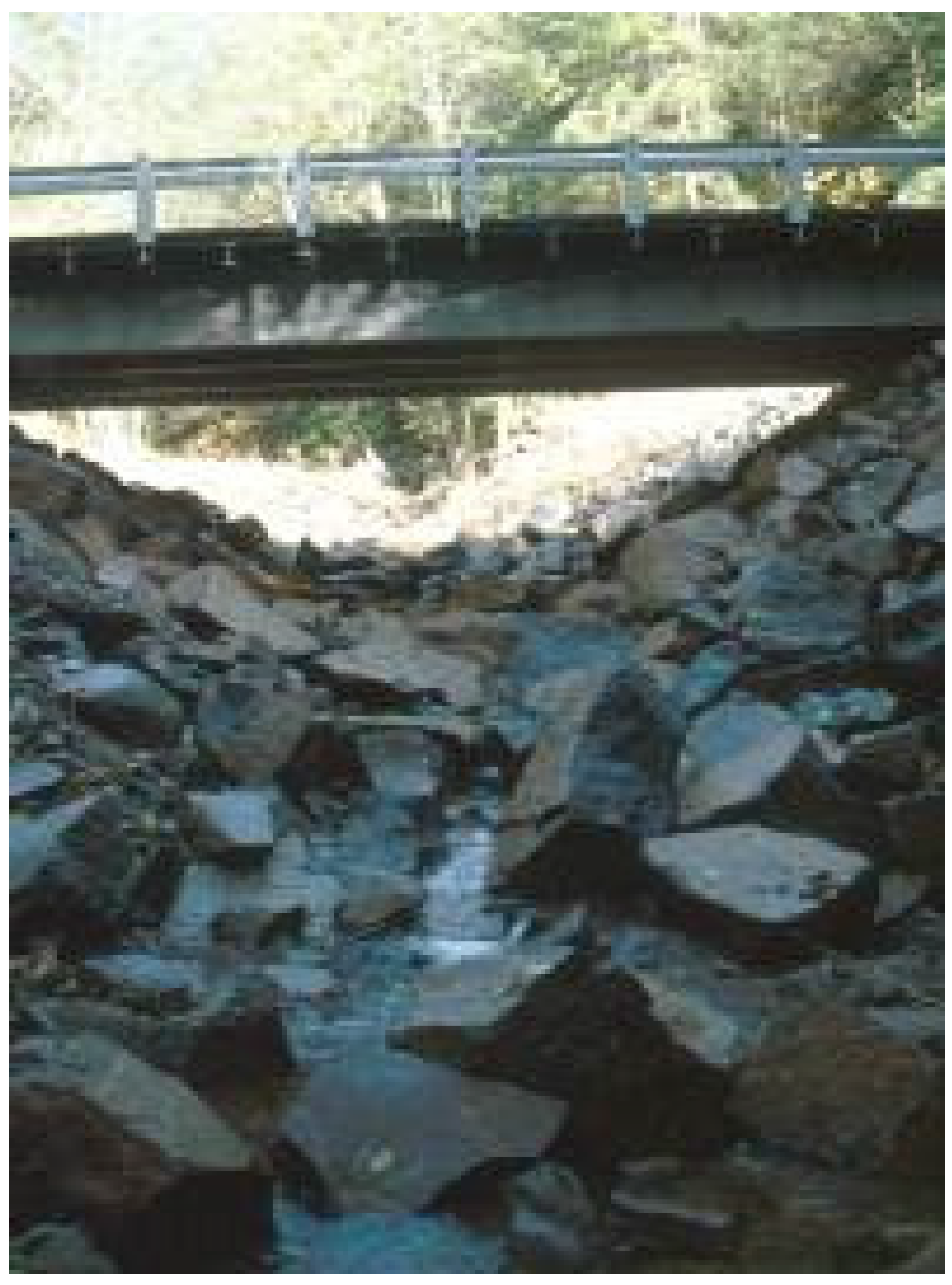
Culvert with upstream sediment deposit.

Figure 6.
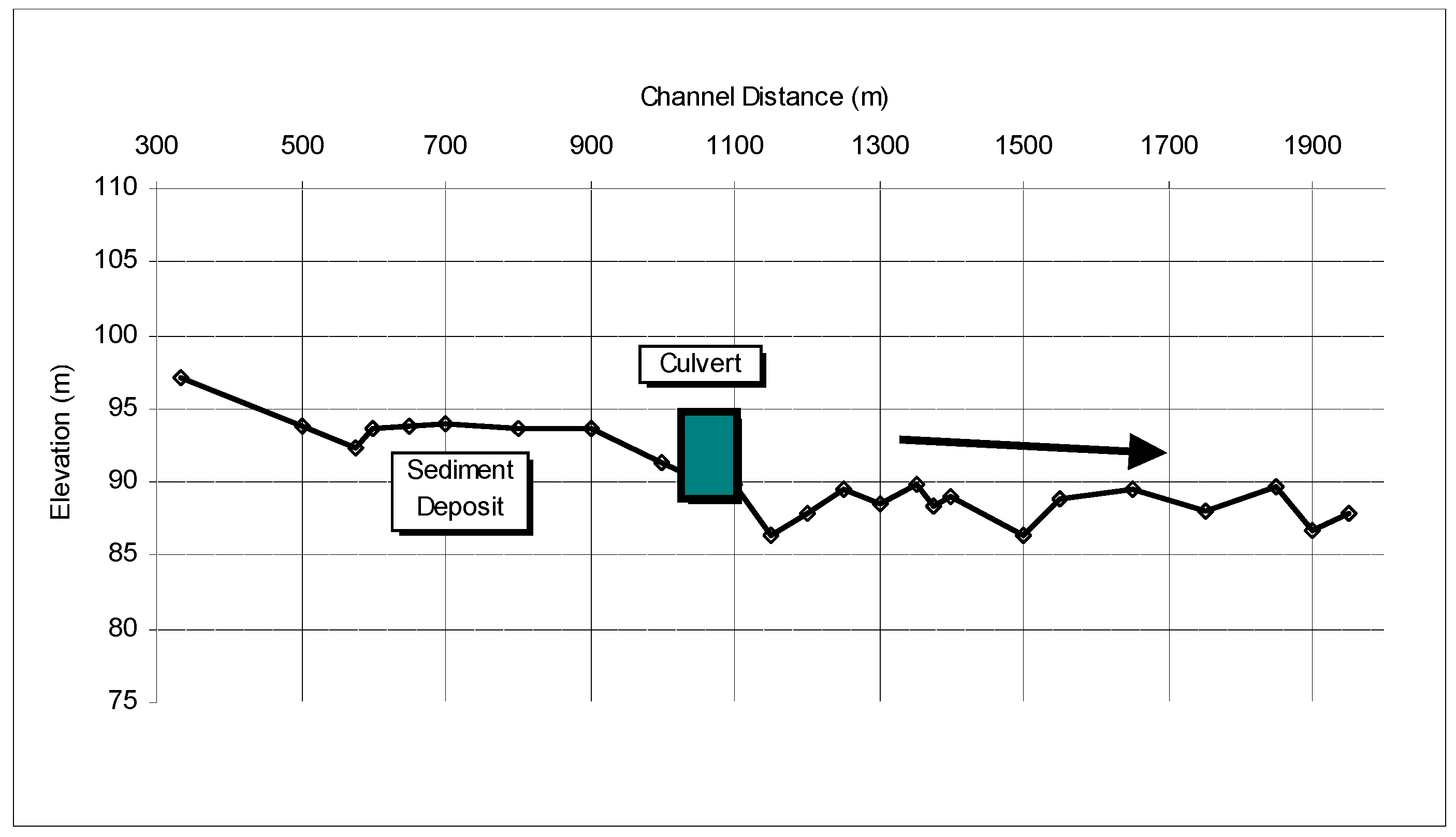
Example longitudinal profile with channel bed off-set depicting systemic downstream incision.
Figure 6.
Example longitudinal profile with channel bed off-set depicting systemic downstream incision.

Figure 7.
Montgomery and Buffington [35] Stream Classes.
Figure 7.
Montgomery and Buffington [35] Stream Classes.

Figure 8.
Large wood placed to reduce channel incision in West Millicoma Creek, Oregon.

Figure 9.
Constructed riffle on Whychus Creek, Oregon.
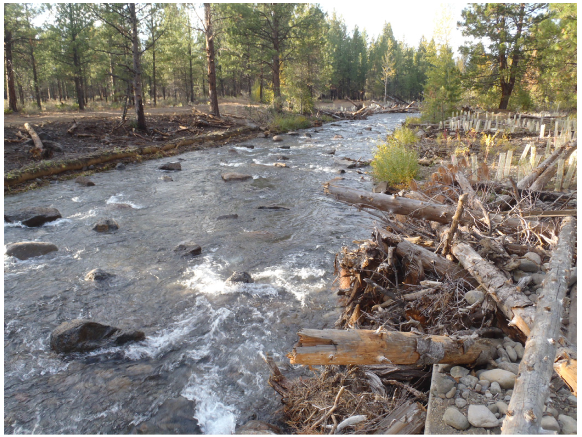
Figure 10.
Rock weir.

Figure 11.
Log weir.

Figure 12.
Constructed Step-Pool (photo courtesy of Rob Sampson).

Figure 13.
Constructed Cascade (photo courtesy of Dan Perritt).


| Decreased Erosional Resistance |
|---|
|
| Increased Erosional Forces |
|
Modified from: Schumm, Harvey, and Watson, 1984 [9].
| Alternative | Common Benefits | Potential Limitations |
|---|---|---|
| Do Nothing |
|
|
| Large Roughness Elements: Wood and Boulders |
|
|
| Constructed Riffles |
|
|
| Constructed Steps |
|
|
| Constructed Cascades |
|
|
© 2016 by the authors; licensee MDPI, Basel, Switzerland. This article is an open access article distributed under the terms and conditions of the Creative Commons by Attribution (CC-BY) license (http://creativecommons.org/licenses/by/4.0/).
Share and Cite
MDPI and ACS Style
Castro, J.M.; Beavers, A. Providing Aquatic Organism Passage in Vertically Unstable Streams. Water 2016, 8, 133. https://doi.org/10.3390/w8040133
AMA Style
Castro JM, Beavers A. Providing Aquatic Organism Passage in Vertically Unstable Streams. Water. 2016; 8(4):133. https://doi.org/10.3390/w8040133
Chicago/Turabian StyleCastro, Janine M, and Aaron Beavers. 2016. "Providing Aquatic Organism Passage in Vertically Unstable Streams" Water 8, no. 4: 133. https://doi.org/10.3390/w8040133
Note that from the first issue of 2016, this journal uses article numbers instead of page numbers. See further details here.