Groundwater Abstraction through Siphon Wells—Hydraulic Design and Energy Savings


Faculty of Civil Engineering & Architecture, Dresden University of Applied Sciences, 01069 Dresden, Germany
*
Author to whom correspondence should be addressed.
Water 2018, 10(5), 570; https://doi.org/10.3390/w10050570
Submission received: 16 March 2018
/
Revised: 19 April 2018
/
Accepted: 23 April 2018
/
Published: 27 April 2018
(This article belongs to the Special Issue Energy Efficient Management of Water Collection, Treatment, Storage and Distribution)
Abstract
:Siphon pipes were used for groundwater abstraction from wells before the development of submersible pumps. Many of the existing and operational systems were built before the 1950s and require rehabilitation. Siphon wells are difficult to design and, therefore, are often equipped with submersible pumps when the system is rehabilitated or renewed. This study presents a novel calculation tool for siphon wells and investigates the energy savings of such system in comparison to an alternative equipment with submersible pumps. A theoretical energy savings of 38% was first estimated compared to individually-operated wells (IOW) for a fictional design example just based on the calculated water levels and abstraction rates. Real energy data from two riverbank filtration (RBF) sites, which operate both siphon and IOW, were investigated in the second part of the study. The analysis of measured data revealed energy savings of 36–69%, confirming the theoretical estimation.
1. Introduction
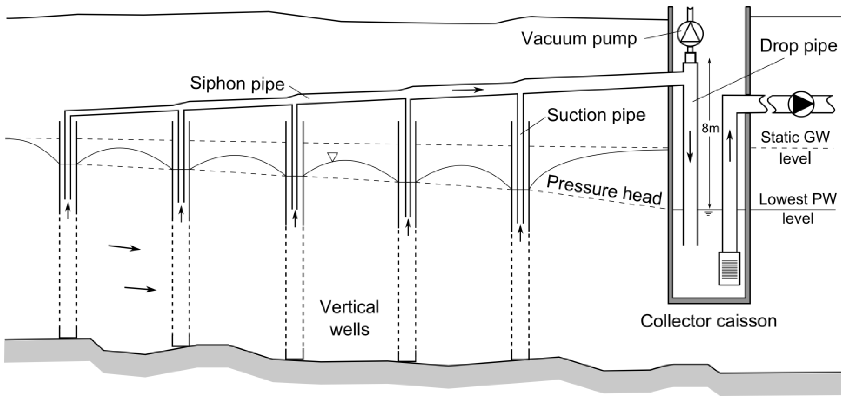
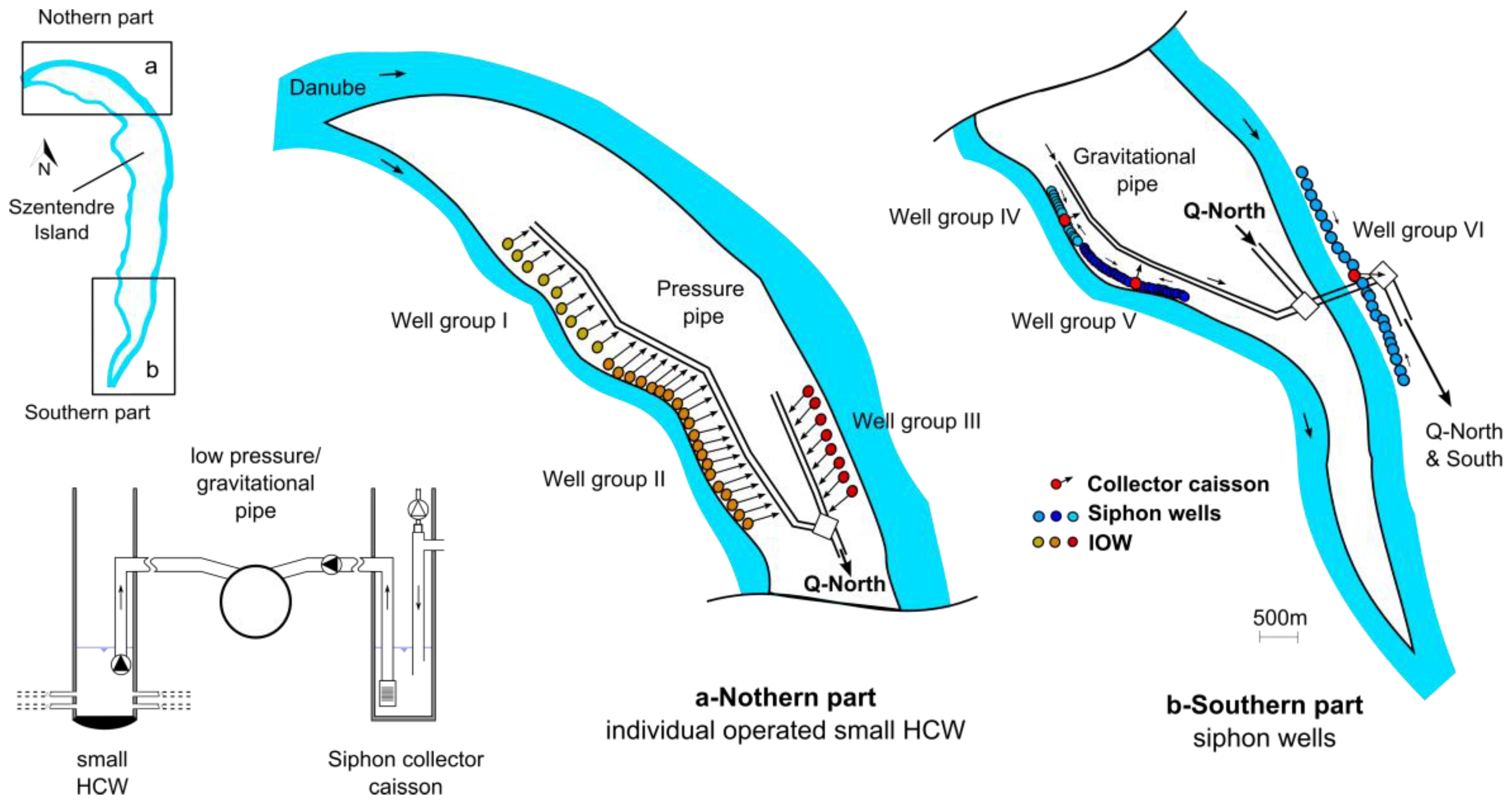
The pumping rate for vertical groundwater wells usually does not exceed 150 m3/h. Several wells are needed for abstracting larger quantities of water (well group). Nowadays groundwater wells are commonly equipped with submersible pumps. Multiple wells from one well group discharge into a main pressure pipe. Before the development of submersible pumps, common groundwater wells were connected via suction pipes to a main gravitational pipe (siphon pipe). The groundwater is hereby abstracted and piped to a central collector caisson without a permanent energy input using gravitational flow (Figure 1). Opposite to the free-flow gravity pipes, the pressure inside the siphon pipe is below atmospheric pressure (vacuum) as the water must be first lifted to the top of the siphon crest. Traditionally multiple well groups were connected via individual siphon pipes to a single collector caisson, which acted as sand collector and open air vessel. Gravitational flow is induced from the abstraction wells to the collector caisson after the siphon pipe has been air-evacuated (primed) using a vacuum pump and the water level inside the collector caisson has been lowered below the static groundwater level. The siphon system only works if (1) the outlet of the drop pipe and the inlets of the suction pipes are permanently submerged, (2) the siphon pipe is continuously air evacuated (degassing of dissolved gases or air entry through small leakages) and (3) the piping is permanently vacuum-tight. At the transition from the siphon to the drop pipe a so called “siphon head” is installed. It collects escaping gas, so that it can be automatically extracted by a vacuum system. The maximum suction head is found at the “siphon head”. It is equal to the suction lift from the lowest pumping level to the inside “siphon head” and should not exceed the vapor pressure of water, which would cause a failure of the gravitational flow. In practice this suction head is limited to 8 m, including a safety margin. The groundwater is pumped from the collector caisson to the waterworks using high-flow pumps.
The first siphon wells were built in Europe in the mid- to late-19th century preferably in Pleistocene deposits along major rivers. Numerous large scale siphon systems were constructed in Germany, Poland, Czech Republic, and Hungary with capacities ranging from 35,000 m3/d (Dresden-Tolkewitz, Germany) to more than 100,000 m3/d (Poznan-Debina, Poland). In recent decades the well-known siphon technology has been replaced by the use of submersible pumps. This was preceded in Germany by an increasing water demand in the mid-20th century. The required pumping rates and the increased screen entry losses caused greater drawdowns inside the collector caisson and the increased water demand reduced the static water levels in the wells. As a result, some well groups could no longer be operated through siphon pipes as their abstraction was limited by the drawdown of the collector caisson and not by the well screens. These wells have been equipped with submersible pumps, because those were able to achieve the necessary drawdown and a higher yield. Another reason for a decreasing use of siphon wells has been the lack of precise calculation tools to design and verify the productivity of such systems, which were historically designed and built by expertise and experience [1]. The computational difficulties lay, similar to horizontal lateral screens, in the interconnection between well yield, well interference, and frictional pipe losses. Thus, an Excel spreadsheet called “SIPHON” [2] has been recently developed for the hydraulic calculation and design of siphon wells.
As of today, many of the old siphon well systems in Europe must be rehabilitated or rebuilt. Due to the difficulties in calculating siphon well systems, the alternative equipment of wells with submersible pumps is often preferred. However, siphon wells offer significant advantages over individually operated wells (IOW): high operational safety in floodplains (no electricity supply), lower maintenance costs due to a reduced number of pumps, easier accessibility and maintenance of the dry mounted pumps, and absence of harmful pressure surges (air vessel). Their most important advantage is that they can contribute to long-term reductions in energy consumption and should, therefore, still be taken into consideration under certain circumstances, especially because the operation of siphon wells appears to be feasible again since the water demand per capita has gone down in many countries in Europe, so that the old siphon systems will not have to be equipped with submersible pumps after well rehabilitation. In fact, recent examples of siphon well rehabilitation in Germany, e.g., in Hamburg [3], Leipzig [4], and Stuttgart [5], prove that the “old-fashioned” siphon systems are worthwhile to be considered.
The crucial reason why siphon wells work more economically than a series of IOW is that these systems require less electrical energy for groundwater abstraction. Instead of pumping from every single well, only two to three high-performance pumps are usually installed to abstract groundwater from the collector caisson. Typically, dry-mounted centrifugal pumps are preferred because they are easier to maintain and have a higher energy efficiency factor compared to submersible pumps. Those suffer from their compact design and multiple energy losses due to cables and transformers. The average total efficiency (motor and pump) of submersible pumps investigated in Germany was in the range of only 41% (n = 2567, [6]) to 48% (n = 360, [7]). A study by the Berlin waterworks reported a mean value of 44% (n = 650) for submersible pumps compared to 72% (n = 44) for dry-mounted centrifugal pumps [8].
Siphon wells are still operated at more than 50 sites in Germany and at several sites in Poland, Hungary, and the Czech Republic. Most of them were constructed before the 1950s and must be rehabilitated in the near future. Planners often have difficulties to mathematically or numerically prove the capacity of such systems during the design stage, so the siphon wells are, nowadays, often equipped with submersible pumps. A state of the art investigation of the potential energy savings of siphon wells in comparison to IOW, which could justify higher investment costs for the rehabilitation of the “old-fashioned” systems, has not yet been published to assist planers and engineers in their decision. This study, therefore, presents (1) an example hydraulic calculation of a fictional lake bank filtration site using a novel hydraulic calculation tool “SIPHON”, which can be used for the design and rehabilitation of siphon well systems and (2) investigates the energy savings of siphon wells per cubic meter of abstracted water based on real data from two riverbank filtration (RBF) sites operating both siphon wells and individually-operated vertical or small horizontal wells.
2. Materials and Methods
2.1. Hydraulic Calculation of Siphon Wells
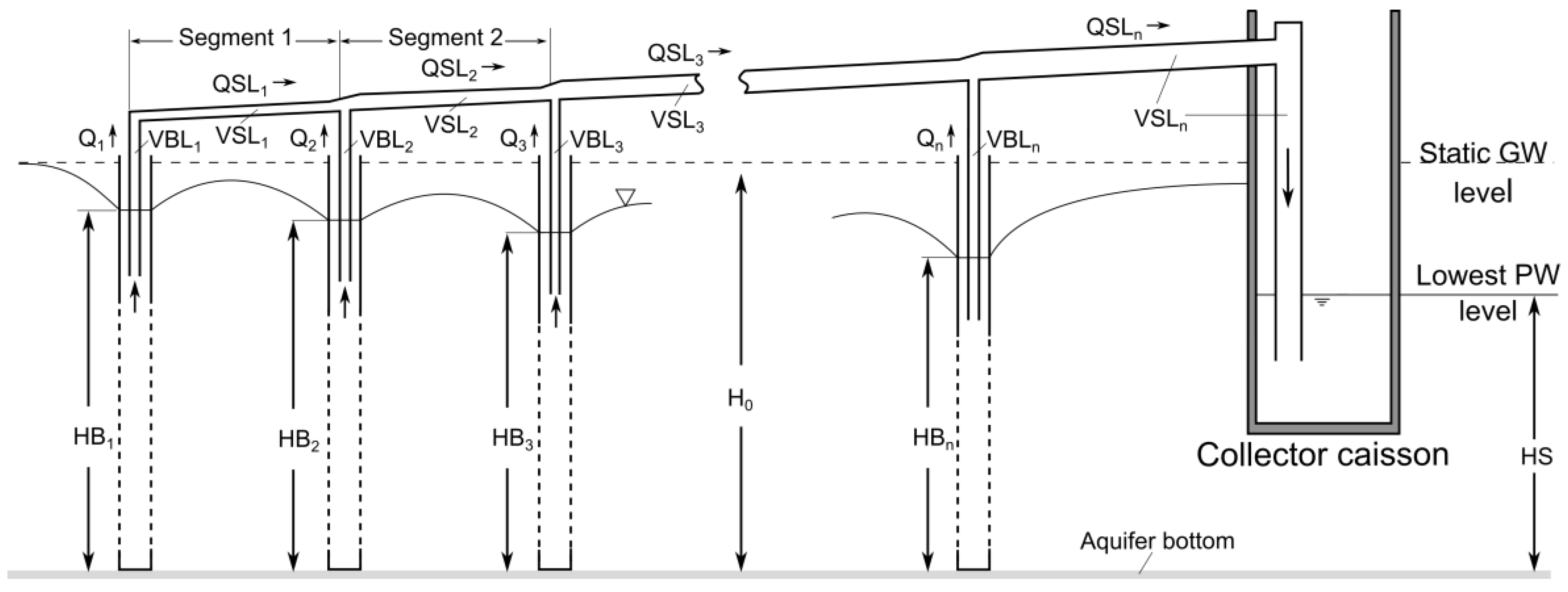
The calculation of inclining siphon pipes is analogous to pressure pipes except that the absolute pressure in siphon pipes is below the atmospheric pressure and the vapor pressure of water should never be exceeded when determining the most economic elevation of the siphon pipe (Figure 1). The first algorithm for the calculation of siphon wells was developed by Paavel (1948) [9] but not useful for system design at that time because of its computational requirements. The MS Excel tool SIPHON [2] is based on Paavel’s algorithm and assumes that (1) all wells influence each other and create a common cone of depression for the steady state, and (2) the radius of influence of a well group, which is not subject to a surface water boundary, cannot be smaller than the distance between the two outermost wells [10]. SIPHON calculates individual well heads and abstraction rates based on a pre-defined pumping water level in the collector caisson. The gravitational flow inside the suction and siphon pipes is controlled by the available driving head. The well water level HBi (m above the bottom of the aquifer) of the well i of a well group with n (-) wells can be calculated using Equation (1) [1] using a counting direction from outside towards the caisson:
with:
where HS (m above the bottom of the aquifer) is the pre-defined pumping water level in the collector caisson, VBLi (s2/m5) is the flow dependent friction loss coefficient of the suction pipe, Qi (m3/s) is the abstraction rate of the well i, VSLj (s2/m5) is the flow dependent friction loss coefficient of siphon pipe segment j, QSLj (m3/s) is the flow rate inside siphon pipe segment j; and Qk (m3/s) is the abstraction rate of the well k. The segment j extends from the joint of the well j to before the joint of well j + 1. The flow-dependent friction loss coefficients are calculated as [1]:
where fd (-) denotes the Darcy-Weisbach friction factor; L (m) is the length of suction pipe well i or the length of segment j; d (m) is the inner pipe diameter; Σζ (-) the sum of local losses; and g (m/s2) is the gravitational acceleration. VSLj=n includes frictional losses of the drop pipe and the “siphon head”. In order to calculate HBi (m), a generalized form of the Dupuit-Thiem equation using the GIRINSKIJ potential allows the superposition of multiple wells including image (hypothetical) wells to represent boundaries for unconfined and confined aquifers [11]:
where Ø0 (m2) is the GIRINSKIJ potential of the static water level; Ø (m2) the GIRINSKIJ potential of the pumping water level inside a well; K (m/s) is the hydraulic conductivity of the aquifer; ri (m) is the distance between the well axis of well i and the bore hole annulus of the currently considered well; and ϕ (ri) is the specific potential as sum of drawdown potentials caused image wells plus well entry losses. Substituting Equation (4) into Equation (1) results in a system of n non-linear equations with n unknown well abstraction rates Qi. The system is solved in Excel using the SOLVER function and the integrated GRG2-code for non-linear systems. The solution algorithm requires a pre-defined pumping water level and a first rough estimate for the well abstraction rate. The tool was tested with four benchmarks and real data from a site using 43 wells connected to three individual siphon pipes [2].
2.2. Site Descriptions
2.2.1. Fictional Lake Bank Filtration Site
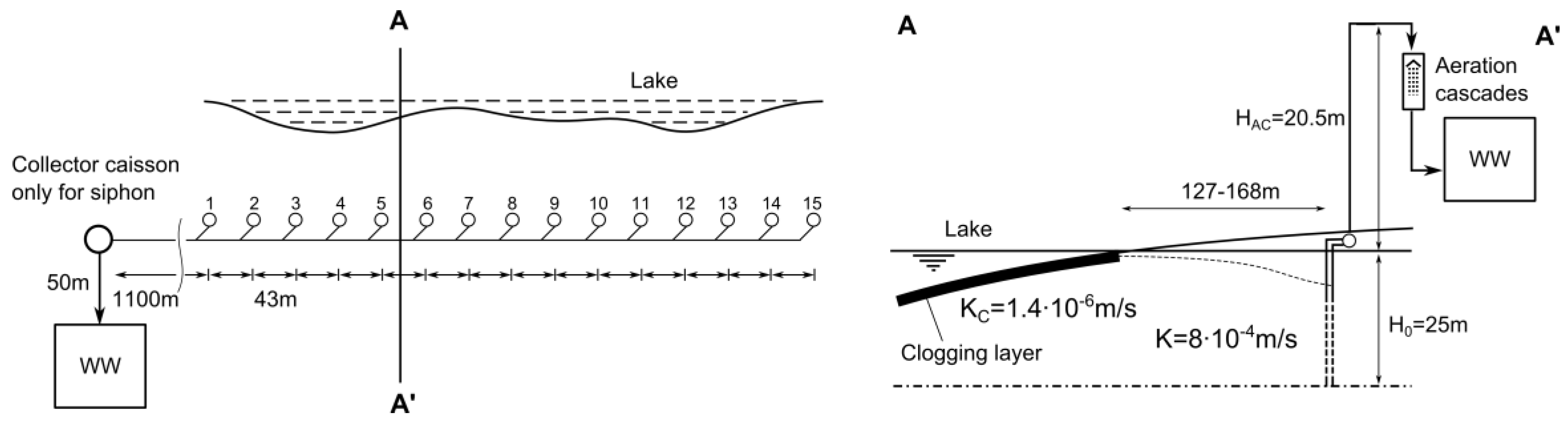
The site layout (Figure 2) was adapted from one of the four benchmarks [12]. A series of 15 vertical wells (VW) with a bore diameter of 1.0 m was placed along a lake shore. The groundwater flow from the individual wells is collected in a common pipe (0.2–0.7 m internal diameter). Two scenarios were calculated: groundwater was abstracted and pumped to the aeration cascades either from IOW or from a collector caisson (siphon wells). Pipe diameters, friction factors, and total abstraction were assumed to be equal for both scenarios. Water levels and frictional head loss were calculated using SIPHON by entering a pre-defined pumping rate (IOW) or a pumping water level for the siphon collector caisson that was iterated to achieve the same total abstraction as for the IOW scenario. The pump head was calculated as sum of well drawdown and static water height HAC above the undisturbed water level (Figure 3).
2.2.2. Waterworks Dresden-Hosterwitz, Germany
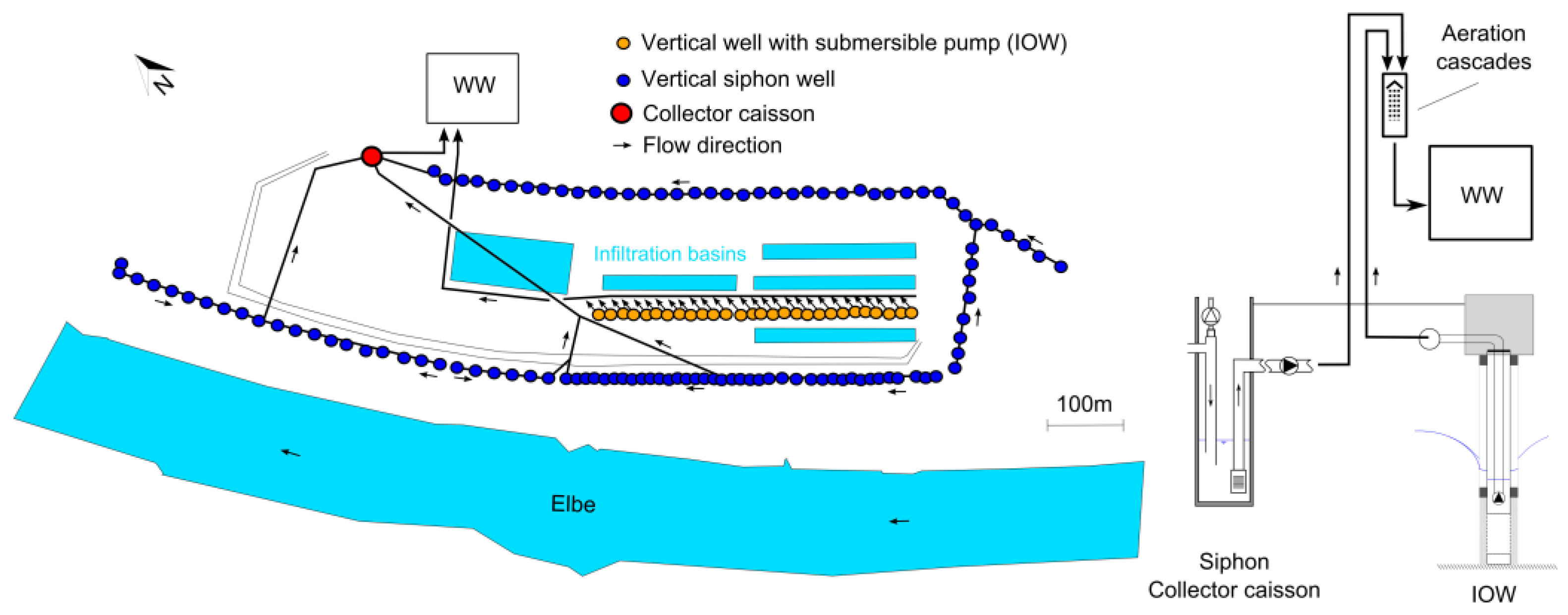
The RBF and managed aquifer recharge site Dresden-Hosterwitz is located on the floodplain of the Elbe River in Dresden. The alluvial aquifer is comprised of coarse sand and gravel with a saturated thickness of 9 to 14 m. Figure 4 shows the waterworks (WW) and the location of 111 vertical siphon wells and 28 IOW. The siphon wells are placed along three individual siphon pipes. The siphon wells have a three/four-layer gravel pack and a bore diameter of up to 2.0 m (Table 1). The well spacing varies between 12 and 24 m. The abstracted water is a mix of artificially recharged water, groundwater and bank filtrate. It is abstracted from one collector caisson and pumped to aeration cascades. The IOW have a bore diameter of 0.8 m and a single layer gravel pack. They abstract artificially recharged water and pump it directly to the aeration cascades. The siphon wells were constructed before 1930, when the available filter screens were not as efficient as modern bridge slot or wire wrap screens. The siphon wells, therefore, outnumber the IOW due to the early trial and error well design and not due to the siphon operation.
2.2.3. Szentendre Island, Budapest Waterworks, Hungary
More than 500 wells are in use on Szentendre Island in the north of Budapest. They penetrate a gravel aquifer (5–8 m saturated thickness) that is recharged by the Danube River. Three different types of wells were investigated regarding their energy consumption: small individually-operated horizontal collector wells (sHCW, well group: I, II, III), vertical siphon wells (VW, well group: IV, V), and siphoned sHCW (well group VI) (Figure 5). The horizontal laterals of the sHCW were constructed using a modified Ranneypress method. Some of the sHCW have laterals on two levels (Table 2). Those were projected radially into the aquifer and extend partly below the riverbed. The VW have a two-layer gravel pack and a bore diameter of 1.2 m (Table 2). The IOW are located in the northern part of the island. Water from these wells is first pumped into a low pressure pipe system and from there connected to a gravitational flow pipe system (1.7–3.3 m internal diameter) on the southern part of the island. Water from the siphon collector caissons is pumped directly into the gravitational pipes that transport the water across the river and downstream towards Budapest city. Each of the three siphon well groups consists of two individual siphon pipes extending along the riverbank in opposite directions with the collector caisson in the middle.
2.3. Energy Assessment
In the case of the fictional lake bank filtration, the calculated pumping head and discharge were entered into the Grundfos quick-sizing web-tool (https://product-selection.grundfos.com/) to derive the energy consumption of dry-mounted and submersible pumps. The pump head was estimated from the elevation of the aeration cascades above static groundwater table HAC (m) (Figure 3) plus the pre-defined drawdown HS inside the collector caisson or the calculated IOW drawdown. Note that the energy consumption does not include, e.g., losses through cables or VFD. Real energy data was available for wells located on Szentendre Island as daily sum counter readings for the duration of one year (1 January–31 December 2015) and for Dresden-Hosterwitz as actual energy values with hourly resolution for a duration of six weeks, when total abstraction decreased from 100% to 20% of its maximum treatment capacity (15 November–31 December 2017). Contrary to the fictional example the real data already included cable losses but also pump “aging” or possible damage to, or incrustations on the impeller.
The specific energy consumption (SEC, kWh/m3) was calculated as energy consumption (kWh) at the pump divided by the volume of water abstracted (m3). The pumping heads on Szentendre Island ranged from 0.8 and 6.3 m due to the well locations and the different pressure zones. The daily energy consumption was pressure-normalized and divided by the mean daily pumping head. No pumping head was available for Dresden-Hosterwitz. However, as indicated in Figure 4, both the siphon wells and IOW have the same static head above ground (aeration cascades) and it was not necessary to normalize the data.
3. Results and Discussion
3.1. Hydraulic Calculation of Siphon Wells
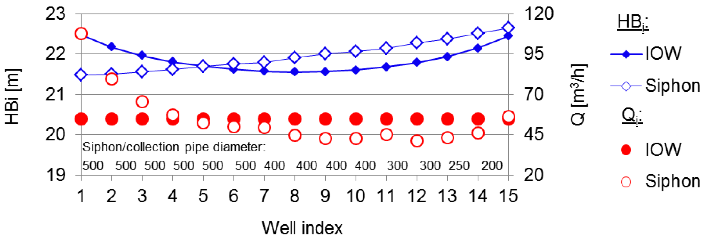
It is generally assumed that in siphon well systems the single well abstraction rate decreases with increasing distance from the collector caisson due to friction. The controlling factor for well yield is the well drawdown. Since the wells influence each other due to the narrow well spacing, a distinction must be made between drawdown from neighboring wells (well interference) and “real” drawdown (well yield). For every well the sum of frictional head loss, well interference and “real” drawdown is equal to the drawdown inside the collector caisson according to Equation (1). The degree of well interference decreases with increasing eccentricity from a maximum plateau value in the middle of the well gallery. If with increasing distance from the collector caisson the increase in friction between two adjacent wells is less than the decrease in well interference, the “real” drawdown (Equation (1)) and, thus, the single well abstraction rate increases towards the outermost wells (Figure 6), which is in opposite to what is generally expected by only assuming an increase in friction but underestimating the effect of well interference. This is even more pronounced at sites with larger pipe diameters [2].
3.2. Energetic Comparison of Siphon and Individually Operated Wells with Submersible Pumps
3.2.1. Fictional Lake Bank Filtration Site
The calculated pump head for a cumulative abstraction of 825 m3/h was 25.2 m for the siphon wells and 24.1–26.2 m for the IOWs. The resulting energy consumption of one dry-mounted centrifugal pump (similar to the ones used in WW Dresden-Hosterwitz, total efficiency 83.8%) pumping the water from the collector caisson to the aeration cascades was 38% (Table 3) less than needed by 15 submersible pumps (IOW). A design total efficiency (motor and pump) of 51.9–54.1% was derived from the Grundfos quick-sizing web tool for new submersible pumps that was approximately 12% higher than the mean value of 41% for submersible pumps used in Germany reported in [6]. Hence, the calculated energy savings may even increase over time assuming a higher degree of aging or corrosion for submersible pumps compared to dry-mounted pumps.
3.2.2. WW Dresden-Hosterwitz
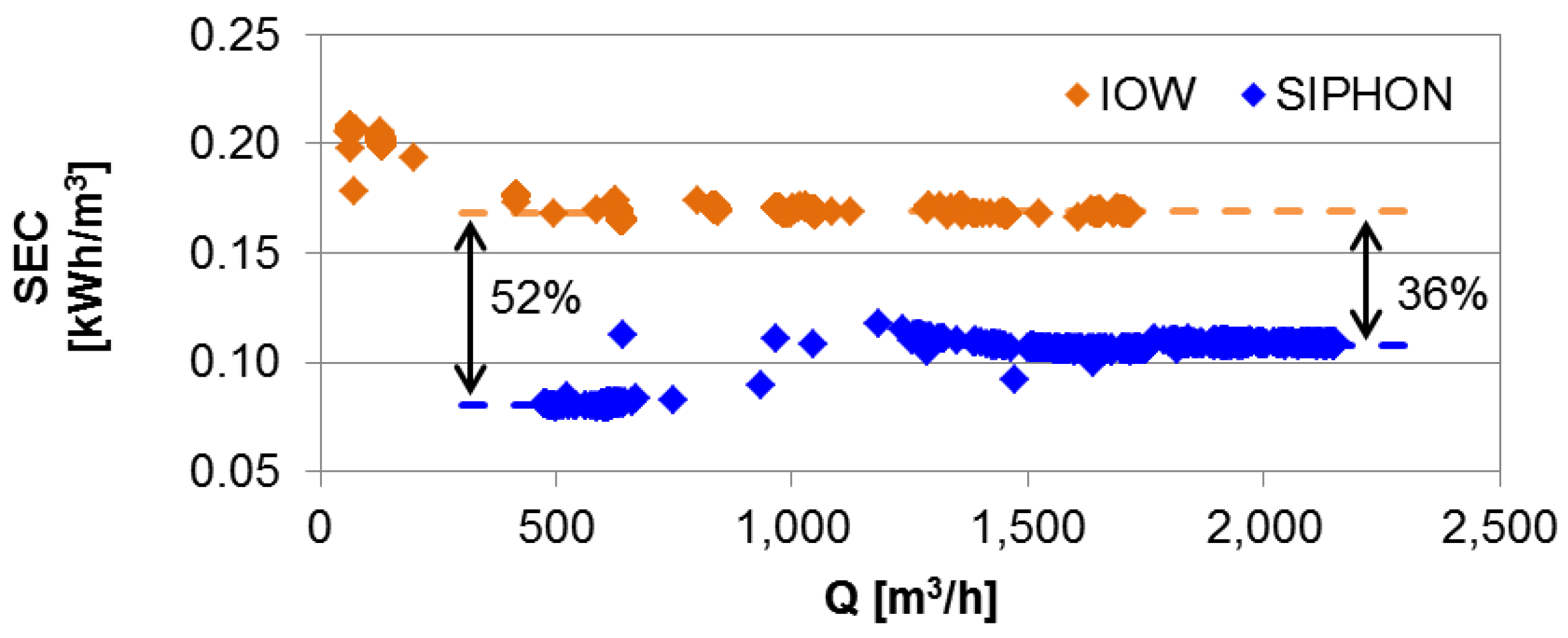
The SEC of siphon wells at WW Dresden-Hosterwitz ranged between 0.081 and 0.108 kWh/m3, 36 to 52% less than measured for the IOW gallery (Figure 7). The offset in the siphon well curve between 750 and 1000 m3/h was caused by the activation of another VFD pump.
3.2.3. Szentendre Island
The pressure-normalized SEC of the siphon well groups on Szentendre Island ranged from 0.004 to 0.011 kWh/(m3·m) compared to 0.018 to 0.028 kWh/(m3·m) for IOW (Table 4) and was, on average, 69% lower than those of IOW. The siphoned sHCW had the lowest SEC because their higher screen intake enables a larger groundwater inflow compared to vertical wells at a similar drawdown. Siphon group V, although equipped with dry-mounted pumps, had a higher SEC compared to siphons IV and VI, which had submersible pumps installed inside the collector caisson. This was unexpected and may have technical reasons, such as pump aging or an operation away from the best operation point due to a different system characteristic curve.
4. Conclusions
The SEC of the siphon wells is 0.026–0.033 kWh/m3 for Szentendre Island with a pump head of ≤5.9 m. The SEC of the WW Dresden-Hosterwitz with a pump head of around 22 to 25 m is 0.081–0.108 kWh/m3. A previous study [13] reported a SEC of 0.05 kWh/m3 for siphon wells along the Rhine River that increased by 20% or 0.01 kWh/m3 during drought periods. In comparison, the SEC of the IOW ranged from 0.053–0.075 kWh/m3 (Szentendre Island) to 0.170 kWh/m3 (Dresden-Hosterwitz). The SEC spans a wide range even for similar well types, thus, data from different sites cannot be easily compared to estimate energy savings. However, the sites investigated in this study each operate both siphon wells and individually operated wells, which allow a comparison.
A 38% reduction in energy consumption was projected for the fictional example calculation by using siphon wells instead of IOW equipped with submersible pumps. Real energy data from two investigated RBF sites indicate savings in the range of 36 to 52% for the WW Dresden-Hosterwitz and on average 69% for Szentendre Island. The real data already include losses for cables and VFDs but also pump aging. It should be noted that these values reflect the current state of the art in pump technology. Future advances in pump technology or different site-specific conditions may increase or decrease the energy savings potential for every individual case. However, the authors are confident that an energy savings potential of 30–50% can be achieved by rehabilitating old siphon wells instead of an alternative equipment with submersible pumps, which justifies the higher investment costs.
The construction of new siphon wells or the equipment of existing wells with siphon pipes offers similar advantages. However, the siphon operation is not feasible at every site and their operation is not as flexible and controllable as IOW. The suction head between the crest of the siphon pipe and the lowest pumping water level inside the collector caisson should not exceed 8 m. The economic depth for trenching and bedding siphon pipes found in German literature up to the mid-20th century was 4.0–4.5 m or maximum 5.0 m for a large number of wells. Thus, the maximum depth for the pumping water level is considered to be around 12 m below the surface. The construction of nearly vacuum-tight pipes and robust vacuum systems is, nowadays, considered state of the art, but requires a high level of precision. The design of siphon systems still remains somewhat challenging, but the freeware tool SIPHON can be used to plan the rehabilitation of an existing system or to design a completely new one.
Supplementary Materials
SIPHON, the freeware MS Excel calculation tool, is available online together with the documentation at www.htw-dresden.de/heber (German and English language) and in the tools section of http://dss.aquanes.eu/ (English language).
Author Contributions
R.B. reviewed the literature, analyzed the energy data, developed the calculation tool and performed the analysis; and T.G. developed the idea, collected literature and contributed expertise in interpreting results.
Funding
All primary data was collected within the “AquaNES” project. This project has received funding from the European Union’s Horizon 2020 Research and Innovation Program under grant no. 689450.
Acknowledgments
The authors gratefully acknowledge support from Budapest Waterworks (Z. Nagy-Kovács and G. Till) and DREWAG Netz GmbH (R. Haas and R. Opitz).
Conflicts of Interest
The authors declare no conflict of interest. The founding sponsors had no role in the design of the study; in the collection, analyses, or interpretation of data; in the writing of the manuscript; or in the decision to publish the results.
References
- Luckner, L.; Eichhorn, D.; Bornitz, U. Calculation of well groups with siphon pipes. Wasserwirtsch. Wassertech. 1971, 21, 354–361. (In German) [Google Scholar]
- Bartak, R.; Grischek, T. Hydraulic calculation of siphon wells. bbr 2018, 69, 64–69. (In German) [Google Scholar]
- Kroening, H. Renewal of the waterworks Curslack. Wasserwirtsch. Wassertech. 2006, 5, 8–15. (In German) [Google Scholar]
- Mauder, S. Rehabilitation of well groups-focus on well chamber design. In Proceedings of the Berlin-Brandenburger Brunnentage, Potsdam, Germany, 12–13 May 2014. (In German). [Google Scholar]
- Scheck, R. Rehabilitation of well group 1 of the state water supply after 100 years of operation. LW-Schriftenreihe 2015, 30, 20–29. (In German) [Google Scholar]
- Huebner, M. Modern system engineering for energy efficient water supply. bbr 2011, 12, 72–78. (In German) [Google Scholar]
- Plath, M.; Wichmann, K. German Technical and Scientific Association for Gas and Water—Information water No. 77 on energy efficiency. Energ. Wasser Prax. 2011, 1, 58–60. (In German) [Google Scholar]
- Sperlich, A.; Gnirß, R.; Schimmelpfennig, S. Subproject 6: Microbial Clogging in Drinking Water Wells, at Its Pumps and in the Raw Water Networks—Developments and Evaluation of Operational Measures; BMBF Project 02WT1189; Berlin Water Works: Berlin, Germany, 2014. (In German) [Google Scholar]
- Paavel, V. Calculation of Well Groups with Siphon Pipes. Ph.D. Thesis, TH Braunschweig, Braunschweig, Germany, 1947. (In German). [Google Scholar]
- Eichhorn, D. Calculation of Well Groups with Siphon Pipes. Ph.D. Thesis, TU Dresden, Dresden, Germany, 1968. (In German). [Google Scholar]
- Luckner, L.; Ziems, J.; Peukert, D.; Tiemer, K.; Eichhorn, D.; Wissel, D. Wells for Groundwater Abstraction-Study on Design Fundamentals; Project Report IG 131/151/70; VEB Projektierung Wasserwirtschaft (WAPRO): Halle/Saale, Germany, 1970; p. 9. (In German) [Google Scholar]
- Busch, K.-F.; Luckner, L. Geohydraulics, 2nd ed.; Dt. Verlag für Grundstoffindustrie: Leipzig, Germany, 1973; pp. 259–263. (In German) [Google Scholar]
- Eckert, P.; Lamberts, R.; Irmscher, R. Impact of river Rhine low flow conditions on the operation of a siphon well group. Energ. Wasser Prax. 2006, 12, 20–23. (In German) [Google Scholar]
Figure 1.
Schematic of five siphon wells and one collector caisson.

Figure 2.
Schematic of the hydraulic calculation parameters.

Figure 3.
Schematic of the fictional lake bank filtration site with 15 wells.

Figure 4.
Map of WW Dresden-Hosterwitz with approximate well locations.

Figure 5.
Map of Szentendre Island with approximate location of selected well groups.

Figure 6.
Calculated well heads and flow rates for IOW and siphon wells using SIPHON.

Figure 7.
Measured SEC as function of discharge for siphon wells and IOW at Dresden-Hosterwitz.


Table 1.
Well design parameters WW Dresden-Hosterwitz, Germany.
| Parameter | Siphon Wells | IOW |
|---|---|---|
| No. of wells | 111 | 28 |
| Year of construction | 1908, 1928/29 | 1980s |
| Well design | VW | VW |
| Filter screen material | Copper & stoneware, slotted & some stainless steel wire | Steel, bridge slotted |
| Filter screen length | 3–5 m | 3 m |
| Screen diameter | 250–300 mm | 350 mm |
| No. of pumps | 3 (in collector caisson) | 46 |
| Type of pump | DM | SP |
| VFD | Yes | No |
VW: vertical well; DM: dry mounted pump; SP: submersible pump; VFD: variable frequency drive.
Table 2.
Well design parameters Szentendre Island, Hungary.
| Parameter | Well Group | |||||
|---|---|---|---|---|---|---|
| I | II | III | IV | V | VI | |
| No. of wells | 9 | 20 | 8 | 56 | 70 | 22 |
| Well design | sHCW | sHCW | sHCW | VW | VW | sHCW |
| Operation | IOW | IOW | IOW | Siphon | Siphon | Siphon |
| Filter screen material | Steel, slotted | Steel, slotted | Steel, slotted | Stainless, bridge slotted | Stainless, slotted | |
| Total screen length | 1465 m | 3540 m | 1733 m | n.a. | n.a. | 3154 m |
| Screen diameter | 219 mm | 219 mm | 200 mm | 300 mm | 300 mm | 200 mm |
| No. of lateral levels | 1–2 | 2 | 1–2 | n.a. | n.a. | 1 |
| No. of pumps | 9 | 20 | 8 | 2 | 3 | 4 |
| Type of pump | SP | SP | SP | SP | DM | SP |
| VFD | Yes | Yes | Yes | Yes | Yes | Yes |
n.a: not available; SP: submersible pump; DM: dry mounted pump; VFD: variable frequency drive.
Table 3.
SEC of siphon wells versus IOW at the fictional lake bank filtration site.
| Parameter | Unit | Siphon Wells | IOW | % Difference |
|---|---|---|---|---|
| No. of pumps | [/] | 1 | 15 | - |
| Model | [/] | NK250-350/342 | SP46-4, 15A21904 | - |
| Motor power draw | [kW] | 75 | 7.5 | - |
| Pump head | [m] | 25.2 | 24.1–26.2 | - |
| Pump discharge | [m3/h] | 825 | 55 | |
| Total efficiency 1 | [%] | 83.8 | 51.9–54.1 | 29.7–31.9 |
| Energy consumption | [kWh/a] | 5.91 × 10⁵ | 9.50 × 10⁵ | 37.8 |
| SEC | [kWh/m3] | 0.082 | 0.132 | 37.9 |
1 Motor and pump.
Table 4.
Measured SEC of siphon wells and IOW at the Szentendre Island (range of IOW in brackets).
| Parameter | Unit | I (IOW) | II (IOW) | III IOW | IV | V | VI |
|---|---|---|---|---|---|---|---|
| Pump head | [m] | 1.3–6.3 | 0.8–6.2 | 1.3–5.4 | 4.3–5.9 | 3.5–5.9 | 2.3–4.5 |
| Energy consumption | [kWh/a] | 4.27 × 10⁵ | 7.48 × 10⁵ | 9.90 × 10⁴ | 7.77 × 10⁴ | 1.02 × 10⁵ | 8.62 × 10⁴ |
| Pressure-normalized SEC | [kWh/(m3·m)] | 0.028 (0.017–0.042) | 0.018 (0.011–0.030) | 0.022 (0.014–0.039) | 0.006 | 0.011 | 0.004 |
| SEC | [kWh/m3] | 0.075 (0.055–0.114) | 0.061 (0.052–0.120) | 0.053 (0.050–0.058) | 0.026 | 0.033 | 0.030 |
© 2018 by the authors. Licensee MDPI, Basel, Switzerland. This article is an open access article distributed under the terms and conditions of the Creative Commons Attribution (CC BY) license (http://creativecommons.org/licenses/by/4.0/).
Share and Cite
MDPI and ACS Style
Bartak, R.; Grischek, T. Groundwater Abstraction through Siphon Wells—Hydraulic Design and Energy Savings. Water 2018, 10, 570. https://doi.org/10.3390/w10050570
AMA Style
Bartak R, Grischek T. Groundwater Abstraction through Siphon Wells—Hydraulic Design and Energy Savings. Water. 2018; 10(5):570. https://doi.org/10.3390/w10050570
Chicago/Turabian StyleBartak, Rico, and Thomas Grischek. 2018. "Groundwater Abstraction through Siphon Wells—Hydraulic Design and Energy Savings" Water 10, no. 5: 570. https://doi.org/10.3390/w10050570
Note that from the first issue of 2016, this journal uses article numbers instead of page numbers. See further details here.