Article

GNSS Measurement of Rain Rate by Polarimetric Phase Shift: Theoretical Analysis

1
College of Meteorology and Oceanography, PLA University of Science and Technology, Nanjing 211101, China
2
School of Science, PLA Information Engineering University, Zhengzhou 450002, China
*
Author to whom correspondence should be addressed.
Atmosphere 2016, 7(8), 101; https://doi.org/10.3390/atmos7080101
Submission received: 16 June 2016 / Revised: 12 July 2016 / Accepted: 19 July 2016 / Published: 5 August 2016

Abstract

:
In this paper, a novel method for rain rate estimation is researched by polarimetric phase shift of the Global Navigation Satellite System (GNSS). The physical process of GNSS signals propagating through rain-filled medium is investigated, by which the cause of polarimetric phase shift is explored. Then, a theoretical model between polarimetric phase shift Δ ϕ and rain rate R is established and simulated, which is based on the oblate spheroid raindrop model, four different popular raindrop size distribution models and raindrop canting angle distribution across the Space-Earth rain path. Additionally, effects of raindrop size distribution, rain path length, raindrop canting angle and temperature on the Δ ϕ -R relation are discussed systematically. Other factors in the slant path such as ice crystals, melting particles and ionosphere are also researched preliminarily. The results show that polarimetric phase shift of GNSS signals, which has a strong correlation with rain rate, can be used to estimate the rain rate, and these influencing factors, raindrop size distribution, rain path length, raindrop canting angle and temperature, are quite important in the process of rain rate measurement. It can be also found that the effect of ice crystals can be negligible, while that of melting particles should be considered, and though ionosphere effects are not obvious, the ionospheric anomalies cannot be neglected in future experiments. This method has potential applications in real-time, continuous, extreme precipitation reconnaissance and numerical weather prediction.

1. Introduction

Polarimetric characteristics of a microwave, when it propagates through a region containing raindrops, have been of great concern in many fields such as radio communication, remote sensing, and radar meteorology [1,2]. Especially in radar meteorology, as the past decades have witnessed the rapid development of the polarimetric weather radar technique, rain rate estimation from radar polarization parameters has been investigated extensively and intensively [3,4,5]. The radar polarization parameters, such as differential reflectivity (ZDR), linear reflectivity difference (ZDP), as well as specific differential phase (KDP), for improving rain rate estimation can be successfully measured [6,7,8].
The enlightenments we can achieve from the proposed polarimetric radar techniques are: (1) The change of the polarization information of a microwave along a propagation link in a rain area can be employed to detect the rain rate; (2) The polarimetric phase shift of a microwave, namely the phase change, is a type of effective information to calculate the rain rate at lower frequencies [7].
However, in radar meteorology, its theoretical research mainly focuses on backward scattering characteristics of cloud particles or rain particles in the S-, C- and X-band, while the forward scattering properties of rain particles in the L-band, especially the forward-scattering polarimetric properties, have been investigated very little. Furthermore, the rain-induced polarimetric properties of GNSS signals, which are right-hand circularly polarized (RHCP) microwaves at frequencies from 1.164 GHz to 1.6155 GHz belonging to the L-band [9], have been systematically studied very little.
Since GNSS constellation has the advantages of low cost, high precision, 24 h availability and worldwide coverage, research on applications of GNSS signals in earth sciences have been booming over the past several decades. Some important parameters of atmosphere and ocean, such as total electron content (TEC), Integrated Water Vapor (IWV), atmospheric temperature and moisture profiles, and sea surface wind field can be detected from GNSS signals [10,11]. Moreover, a polarimetric concept employing GNSS Radio-Occultation (RO) signals to detect heavy rain was first proposed by Cardellach et al. [12]. The concept will be tested on a spaceborne experiment aboard a Low Earth Orbiter, in the Radio-Occultation and Heavy Precipitation (ROHP) experiment aboard the Spanish Earth Observation satellite PAZ [13].
Extending the research by Cardellach et al. [12,13], this paper intends to probe into the influencing factors on rain rate estimation by GNSS polarimetric phase shift in theory, which will play an important role in the design of measuring equipment, the implementation of experiments and the future data processing algorithms. Section 2 describes the physical-mathematical relationship model between polarimetric phase shift and rain rate using the oblate spheroid raindrop model, four different raindrop size distribution models and raindrop canting angle distribution across the Space-Earth rain path. The relation between the polarimetric phase shift of GNSS signals and rain rate is discussed in detail in Section 3; the effects of raindrop size distribution, rain path length, raindrop canting angle and temperature on the polarimetric phase shift and rain rate relation model are investigated systematically; we also investigate the effects of ice crystals, melting particles and the ionosphere. Finally, some practical conclusions are drawn in Section 4.

2. Methods

Due to the nonspherical shape of the falling raindrops, and the tendency for raindrops to align in a particular direction at one time (canting angle) [14], GNSS polarimetric phase shift occurs. Polarimetric phase shift, namely the phase difference between the horizontally and vertically polarized components, can be expressed as
Δ ϕ = ϕ h ϕ v
where Δ ϕ is in millimetres, ϕ h and ϕ v denote the horizontally and vertically polarized phases, respectively.

2.1. Nonspherical Raindrop Shape Model

In the calculations, information on the raindrop shape is necessary. In the past, the nonspherical raindrops model had been investigated by several experts [15,16,17]. There are various models to describe the shape of nonspherical raindrops, of which a Beard and Chuang (BC) model obtained by Beard and Chuang [15] is more precise and widely utilized in many researches. The axis ratio (ratio of minor to major axes) of the BC model can be expressed by a fourth-order polynomial as
a b = 1.0048 + 1.14 × 10 3 r e q 1.0512 × 10 1 r e q 2 + 2.9456 × 10 2 r e q 3 2.6832 × 10 3 r e q 4
which is in good agreement with the numerical results of the BC model [18]. In Equation (2), r e q is the radius of the equivolumic spherical drop in units of millimeters ( 0 < r e q 3.5 ); a and b represent the minor and major axes of oblate spheroid drops, respectively.
Due to various aerodynamic forces acting on them, the axes of nonspherical raindrops will cant from the vertical direction. The canting angles of raindrops subsequently form an angle distribution. A Gaussian distribution for instantaneous canting angle θ is assumed with a mean angle θ 0 and a standard deviation of σ θ . If the standard deviation is 0°, all the rain canting angles will have a fixed orientation.

2.2. Raindrop Size Distribution

Rain rate estimation fundamentally requires some knowledge of the raindrop size distribution. The raindrop size distribution is variable in both spatial and temporal variations and shows dependence on geographical location, local climate and precipitation type [18]. Therefore, the raindrop spectra have infinite theoretical distributions [19]. Nevertheless, it has been found that they can be generally fitted to some mathematical models, such as Exponential distribution [20], Gamma distribution [21,22], Lognormal distribution [23] and Weibull distribution [24]. These models with different parameters are often used and investigated by many authors, so they will be assumed and used here. Expressions and assumed parameters of these raindrop size distributions for theoretical research are shown in Table 1.
In Table 1, r is the radius of the equivolumic spherical drop in millimeters; N(r)dr is the number of drops of size r to r + dr; R is the rain rate in mm·h−1. Here, the maximum acceptable value of rain rate R is set up to 150 mm·h−1. From Table 1, it can be seen that since some parameters are functions of the rain rate, the raindrop size distribution is connected with the rain rate.

2.3. Calculation Model of Polarimetric Phase Shift

Polarimetric phase shift can be calculated from
Δ ϕ = L K D P d l
where L is the path length through the rain-filled medium; K D P is the specific differential phase in mm·km−1. The rain-induced K D P across Space-Earth links can be obtained from the following expression [25]:
K D P = λ 2 2 π ( 1 2 σ θ 2 ) Re ( f h ( r e q , 0 ) f v ( r e q , 0 ) ) N ( r e q ) d r e q
In Equation (4), λ is the wavelength of GNSS signals; σ θ denotes the standard deviation of the canting angle distribution; r e q is the radius of the equivolumic spherical drop in millimeters; N ( r e q ) is the raindrop size distribution; f h and f v are the forward-scattering amplitudes in the horizontal and vertical direction, respectively. Typically, the forward-scattering amplitudes for nonspherical drops can be obtained using Rayleigh Scattering Approximation, Boundary Element Method (BEM), Discrete-dipole approximation (DDA), Point Matching (PM), Fredholm Integral Equation, T-matrix and Generalized Multipole Technique software (GMT) [26,27,28,29,30].
By utilizing the above methods, a physical-mathematical relationship model between GNSS polarimetric phase shift Δ ϕ and rain rate R can be set up. The feasibility of using the specific Δ ϕ - R relation to estimate the rain rate will be discussed and some important influencing factors will be also analyzed in the following section.

3. Results and Discussion

3.1. Variations of Polarimetric Phase Shift with Rain Rate

Since the frequencies of GNSS signals are in the L-band, the raindrop scattering is in the range of applicability of the Rayleigh scattering hypothesis. Therefore, polarimetric phase shift can be calculated using the Rayleigh Scattering Approximation theory for oblate raindrops at the rain rate between 1 and 150 mm·h−1. The United States’ Global Positioning System (GPS), which has two frequency bands known as L1 (1.57542 GHz) and L2 (1.2276 GHz), will be employed in this paper.
Values for the refractive index of water are evaluated at different frequencies of incident electromagnetic waves and temperatures from equations given by Ray [31]. The temperature of 20 °C is used. The elevation of the GPS satellite is assumed to be 0° in the condition of GNSS Radio-Occultation, at which the polarimetric phase shift is probably the most intense [12]. Since the Gamma distribution is widely accepted and used by radar meteorologists and other researchers to model natural raindrop size distributions [4,15,32], it is chosen in the simulation.
Figure 1 presents the dispersive characteristics of polarimetric phase shift experienced by a 20-km-long, uniformly filled rain path for rain rates from 1 to 150 mm·h−1 at the L1 (1575.42 MHz) and L2 (1227.60 MHz) frequencies of GPS signals using a distribution of canting angles of 0° with a standard deviation of 0°. The results show that the polarimetric phase shift goes up smoothly with the increasing rain rate. This is due to the fact that heavy rain has more large nonspherical raindrops which can, as a result, cause more phase shift [17]. The results are also in consistent with the description by Al-Rizzo et al. [33] and Cardellach et al. [13]. In addition, we also note that the polarimetric phase shift’s tendency is similar at different frequencies. However, there are some other factors such as ice crystals, melting particles and the ionosphere which may cause polarimetric phase shift at slant paths. They will be estimated preliminarily in this section.
Figure 1 indicates that the rain polarimetric phase shift of GNSS signals is sensitive to the rain rate. Therefore, rain rate estimation based on Δ ϕ - R relation is theoretically feasible.

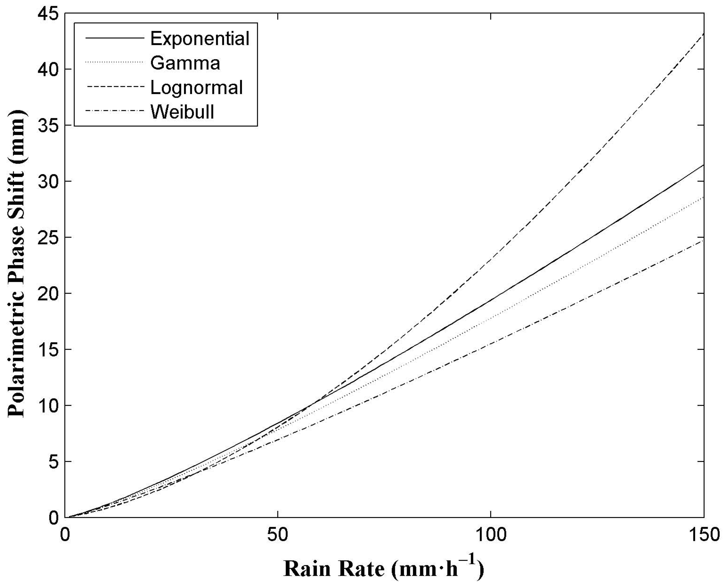
3.2. Effect of Raindrop Size Distribution

From Equation (4), the raindrop size distribution is quite crucial in the calculation. Four raindrop size distributions, namely Exponential distribution, Gamma distribution, Lognormal distribution and Weibull distribution, shown in Table 1, are used to discuss its effect on polarimetric phase shift. Figure 2 shows the effect of raindrop size distributions on the Δ ϕ - R relation using four different distributions at the L1 (1575.42 MHz) frequency of GPS signals, with a distribution of the canting angles of 0° with a standard deviation of 0°. It can be found that when the rain rate is less than 40 mm·h−1, the difference of the polarimetric phase shift at different raindrop size distributions is almost the same, while along with a larger rain rate, it becomes obvious. Therefore, it is required to obtain the characteristics of the local raindrop size distribution in advance. Also, a disdrometer or a polarimetric radar must be used to get more details on the raindrop size distribution during a field experiment.

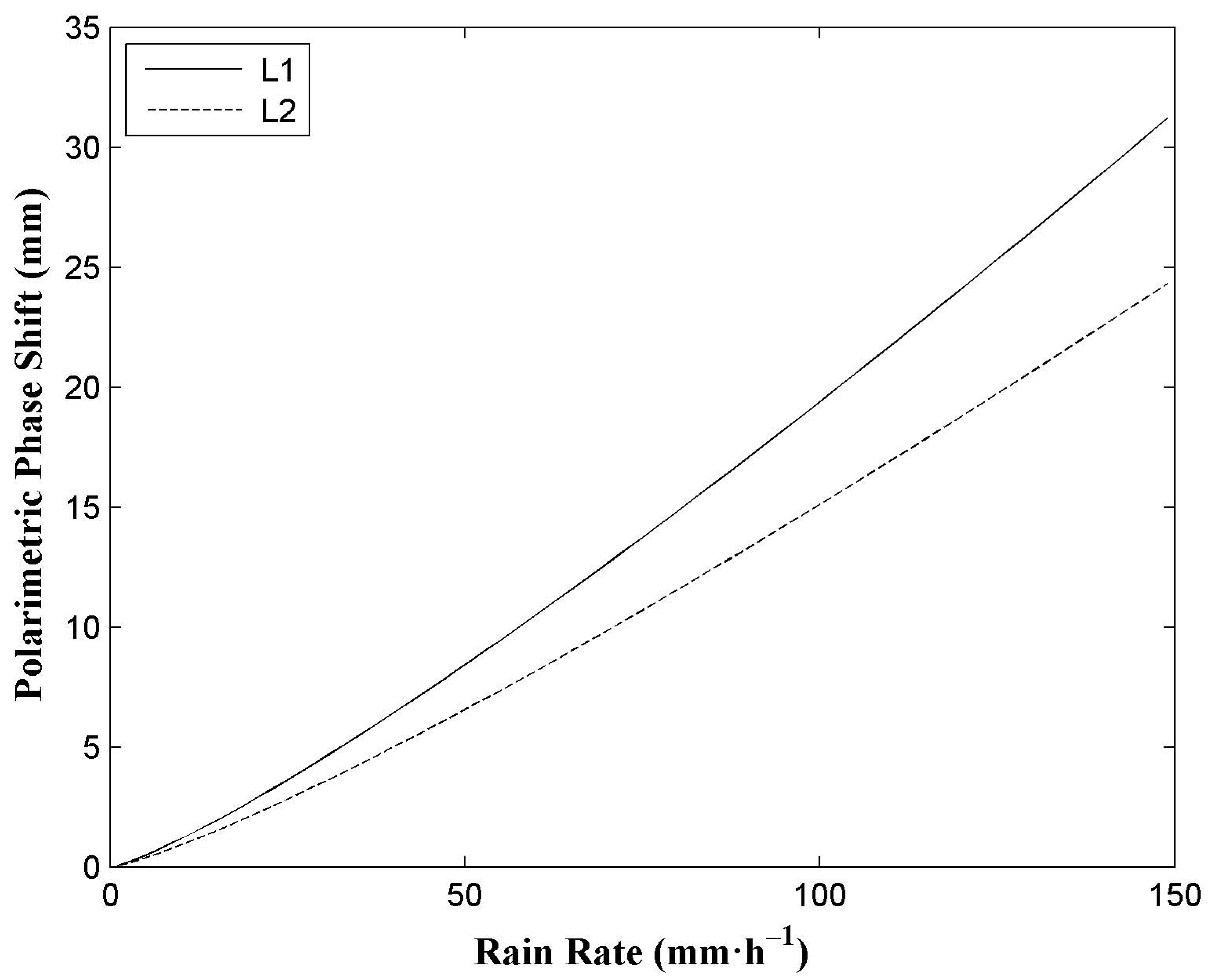
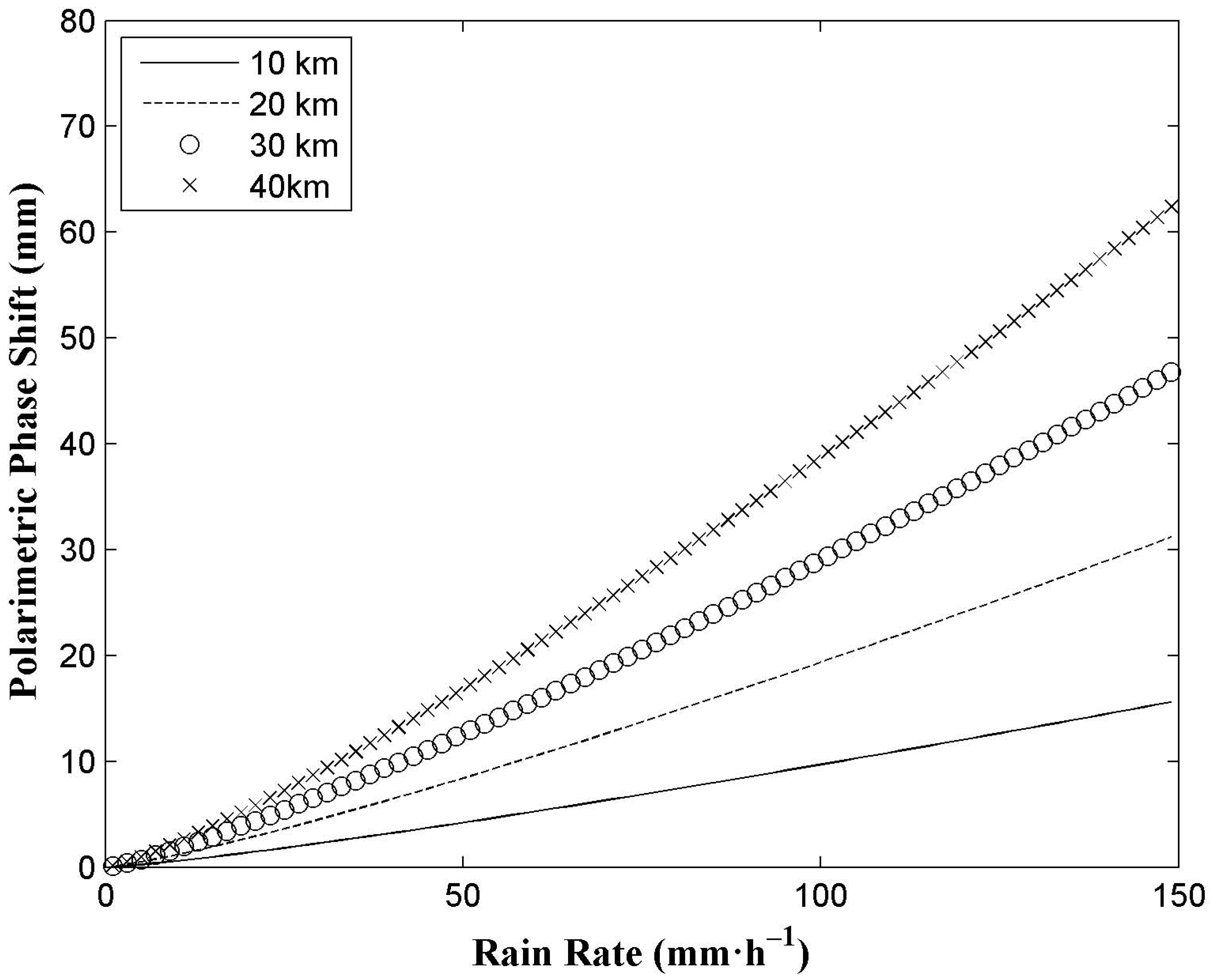
3.3. Effect of Rain Path Length

The rain path length is an important factor to calculate the polarimetric phase shift from Equation (3). Figure 3 shows the effect of the rain path length on the Δ ϕ - R relation over a range of rain path lengths at the L1 (1575.42 MHz) frequency of GPS signals using a distribution with canting angles of 0° with a standard deviation of 0°. The calculations are performed for path lengths of 10, 20, 30, and 40 km assuming a uniform rain structure. The temperature of 20 °C is used. It can be seen that the polarimetric phase shift has increased with the increase of the rain path length. Obviously, an accurate rain path length is of vital importance to calculate the polarimetric phase shift. Additionally, the calculation model of the rain path length depends on the rain area and the geometry of the Space-Earth link (see Figure 1 in [34]). The rain height and horizontal projection of the rain path length are needed. Rain height can be attained from the empirical formula in ITU-R P.839-2 [35] or from other methods such as radiosonde. In addition, the horizontal projection of the rain path length can be achieved from the simultaneous satellite cloud image or weather radar data. In addition, it is obvious that in order to get a larger polarimetric phase shift for the GNSS receivers, a lower elevation of the GNSS satellite is recommended.

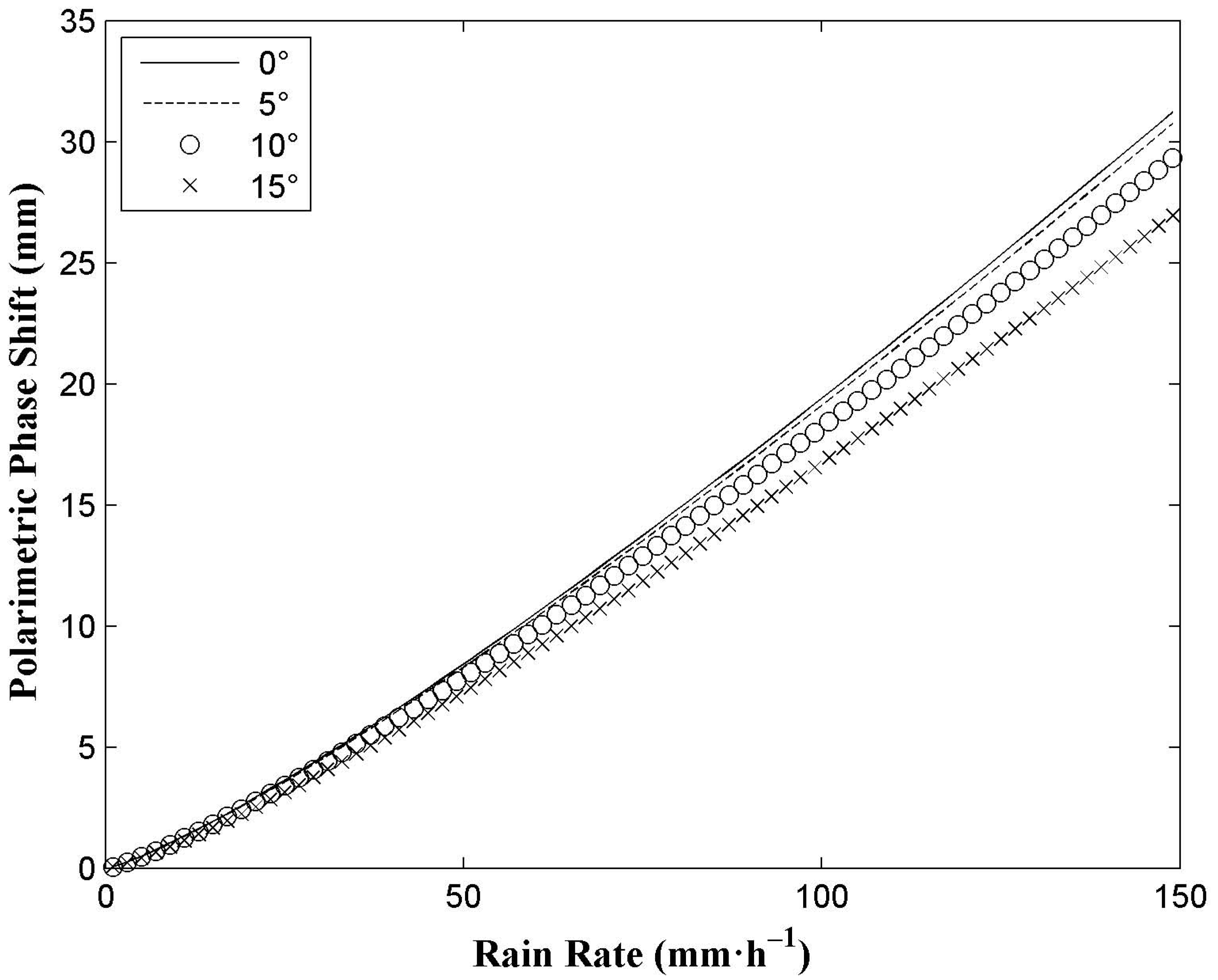
3.4. Effect of Raindrop Canting Angle

In the nonspherical particle scattering algorithm, the raindrop canting angle has a serious effect on the scattering properties [26]. Thus, it is necessary to take the raindrop canting angle distribution along the rain path into consideration in these calculations. In Figure 4, the effect of the raindrop canting angle on the Δ ϕ - R relation over a range of standard deviations of the canting angle distribution at the L1 (1575.42 MHz) frequency of GPS signals is presented for a 20-km-long, uniformly filled rain path.
The standard deviations of the canting angle distribution are assumed as 0°, 5°, 10°, and 15° [36]. From Figure 4, it can be seen that when the rain rate is less than 50 mm·h−1, this effect of the standard deviations of the canting angle distribution is quite small, while it becomes larger with heavier rain. Therefore, it is necessary to measure the microphysical property of raindrops with some instruments such as a disdrometer for estimating heavy rain. Besides, it indicates that the Δ ϕ - R relation can be used to estimate the rain rate at different canting angle distributions.

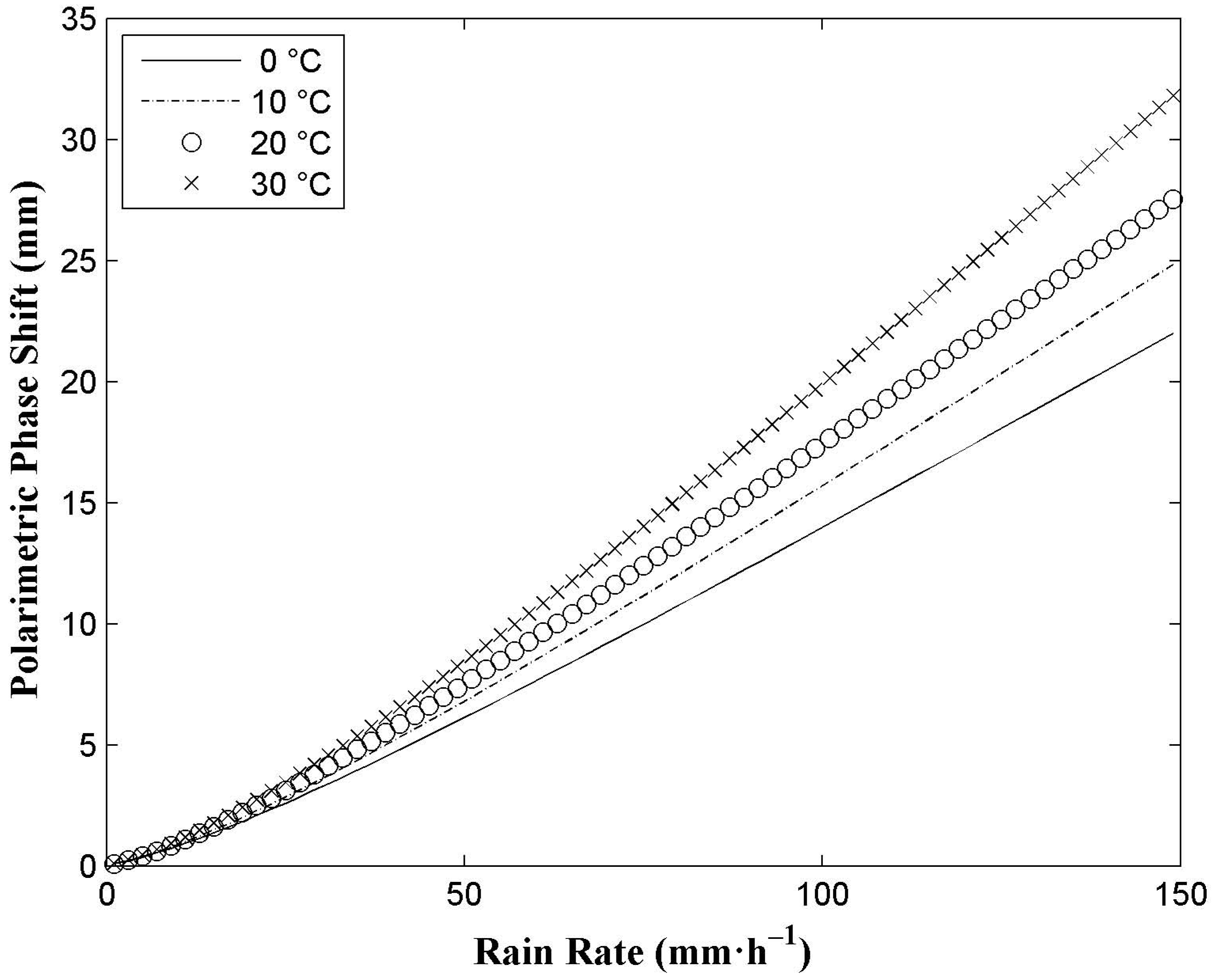
3.5. Effect of Temperature

In the above calculations, temperature is also an influencing factor. Figure 5 represents the effect of temperature on the relation between the polarimetric phase shift and rain rate over a range of temperatures by a 20-km-long, uniformly filled rain path at the L1 (1575.42 MHz) frequency of GPS signals. Temperatures of 0 °C, 10 °C, 20 °C, and 30 °C are employed.
From Figure 5, it can be seen that the values of polarimetric phase shift are not the same at different temperatures. When the rain rate is below 25 mm·h−1, the effect of temperature is not obvious, but when it is above 25 mm·h−1, the polarimetric phase shift becomes larger along with the increasing temperature. This implies that temperature is inevitable in the future rain rate measurements.

3.6. Effects of Cloud Particles

Another source of polarimetric phase shift on a Space-Earth path for GNSS signals, in addition to raindrops, is the presence of cloud particles, such as ice crystals in clouds at high altitudes and melting particles in the melting layer. So, it is necessary to assess the contributions of these nonspherical drops to polarimetric phase shift in theory.

3.6.1. Preliminary Assessment of the Effect of Ice Crystals

To assess the effect of ice crystals on the GNSS signals (L1 frequency), for simplicity, calculations were performed for variable columns and plates with hexagonal shapes [37], characterized by their aspect ratios; sizes range from 0.05 mm to 5 mm in the maximum dimensions. The aspect ratio is designed to be 8, 2, 1, 0.1, and 0.05 for long columns, short columns, block columns, thick plates, and thin plates, respectively [38]. The exponential size distribution of the form
N ( D ) = N 0 exp ( 3.67 D / D 0 )
is assumed to describe the distribution of ice particles, where N 0 = 124.54   m m 1 μ m 3 , D 0 = 1   m m are chosen [39]. The complex refractive index of ice can be calculated from [40]. The discrete dipole approximation (DDA) is employed to calculate the single scattering properties of ice particles [28]. Thus, KDP (Equation (4)) induced by ice crystals at different shapes of ice can be obtained, as presented in Table 2. Compared with the range of rain-induced KDP (about 0–1.5 mm·km−1), Table 2 shows that ice-induced KDP is quite weak. This may be due to the fact that the number concentration of ice particles is sparse at high altitude, which can be seen in Equation (5). Therefore, the effect of ice crystals can be neglected.

3.6.2. Preliminary Assessment of the Effect of Melting Particles

A physical model of the melting layer of precipitation can be seen in the study by Zhang [41], which enables us to simulate the polarimetric characteristics of GNSS signals propagating through the melting layer. This physical model mainly contains the vertical distribution of the concentration and type of melting particles. However, the differences in this simulation are the shapes and distributions of these particles. They are ice-water concentric particles, with a core of ice and a mantle of water, and elliptical shapes with an axis ratio of 0.8 are assumed. The Gamma raindrop size distribution (in Table 1) is used. The thickness of the melting layer is assumed to be 1420 m [41] and the layer is divided into 10 equal intervals with the mass fraction Q = Mw/M (ratio of the mass melted to water in the melting particle Mw to the mass of the whole particle M) ranging from 0 to 1. The DDA is also used to calculate the single scattering properties of melting particles with the shapes of two concentric ellipsoids. Thus, the polarimetric phase shift induced by the whole melting layer can be obtained from Equations (3) and (4).
Figure 6 shows the polarimetric phase shift induced by the whole melting layer for rain rates from 1 to 150 mm·h−1 at L1 (1575.42 MHz). In Figure 6, along with the increasing rain rate, it shows an upward trend, finally reaching the highest point of 1.06 mm. Compared with the rain-induced polarimetric phase shift (Figure 1), the effect of melting particles is obvious, which is a kind of error and should be eliminated in the future data processing. Therefore, some information such as the base and depth of the melting layer, calculated from polarimetric radar data, TRMM satellite data or Cloudsat satellite data, is essential to assess the contribution of melting particles.

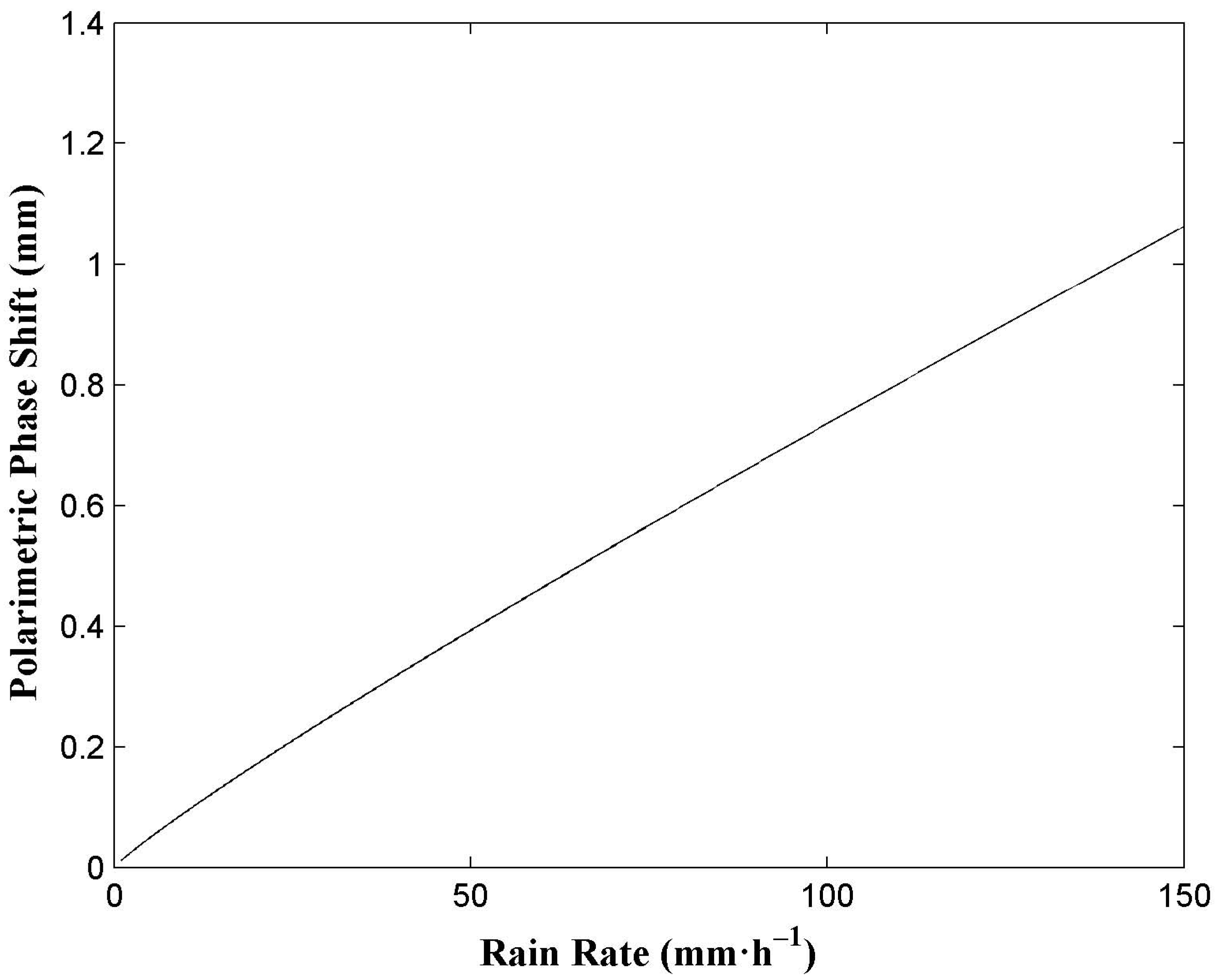
3.7. Effects of the Ionosphere

Firstly, the effects of the ionosphere on GNSS signals are phase delays and amplitude fades [42,43]. The phase delays, for a single frequency of GPS signals, have no influence on the phase shift. In most cases, amplitude fades, mainly due to ionospheric scintillations, have little effect on GPS positioning and the measurements of polarimetric phase shift. However, strong levels of scintillation can produce abrupt, severe fade in a signal level [44], which may lead to the loss of lock. During this period, the data cannot be used.
The polarimetric characteristic is the major concern in this research. It includes phase scintillation, Faraday rotation and Cotton-Mouton effects. The phase scintillation makes a signal hard to track and may also cause the receiver to lose lock in some extreme cases. At this time, the data received should be deleted. Since the ionosphere consists of plasmas containing free electrons and there is a geomagnetic field in the ionosphere, Faraday rotation and Cotton-Mouton effects may occur for some kinds of waves [45]. However, the right-hand circularly polarized GNSS signals are not subject to Faraday rotation [46].
Cotton-Mouton effects, which are proportional to electron density and the magnetic field perpendicular to the direction of propagation, can induce phase shift between the horizontal and vertical components of a wave. Thus, this can change its polarization shape. The phase shift of the GPS L1 frequency by the ionosphere is estimated by the calculation model in Gaudio et al. [45]. The International Geomagnetic Reference Field (IGRF) model [47] and International Reference Ionosphere (IRI)-2007 [48] have been used. The latitude and longitude of Nanjing (32°N, 119°E) and 8 August 2015 are taken as an example here. The incidence angle of 10° is assumed. In these conditions, the phase shift is 0.0092°, which is so small that the polarization shape is still right-hand circular polarization. This may be due to the fact that the magnetic field is quite weak. In summary, except for the period of extreme ionosphere scintillation, the ionosphere has little effect on the rain rate estimation.

4. Conclusions

This study has shown the theoretical analysis of measuring the rain rate based on the polarization parameter of GNSS signals, the polarimetric phase shift Δ ϕ . Importantly, the Δ ϕ - R relation of GNSS signals can be performed by the physical-mathematical model. The numerical results in this study reveal that the Δ ϕ - R relation is feasible for estimating the rain rate. Furthermore, the effects of raindrop size distribution, rain path length, raindrop canting angle and temperature have been discussed. Comparison of these related figures indicates that rain path length is the principal parameter to take into account, raindrop size distribution is also quite essential, and temperature is a much more significant parameter than the variance of the canting angle. Furthermore, the effects of ice crystals, melting particles and the ionosphere have also been estimated. It is found that the effect of ice crystals is literally negligible, while the contribution of melting particles should be considered, and though the effects of the ionosphere are small, the ionospheric anomalies cannot be neglected in experiments. To our knowledge, the results of polarimetric phase shift of GNSS signals for the rain rate at different rain path lengths, raindrop canting angles and temperatures have never been presented before.
From the above methods, the polarimetric phase shift depends mainly on the specific differential phase (KDP), which has several advantages. As the GNSS signals propagate through the rain-filled medium, KDP is independent of receiver and transmitter calibrations, not affected by attenuation and not biased by ground clutter cancellers [49].
Since the GNSS measurement of rain rate by polarimetric phase shift is a novel method, it may be doubted whether it will work in practice. Polarimetric phase shift, namely phase change information, can be measured by horizontal and vertical antennas. Furthermore, the current GNSS receiving and data processing system can measure the phase change precisely at the magnitude of millimeters in the carrier phase positioning or GPS radio occultation detection [50,51].
Considering the detectability of the polarimetric phase shift, a longer rain path length and a lower elevation of the GPS satellite are suggested in application. A series of experiments are being designed to verify this theory.

Acknowledgments

The authors would like to thank Estel Cardellach Galí and her team for their assistance with some techniques regarding the measurements of rain-induced depolarization characteristics of GPS signals. Many thanks to Bruce T. Draine and Piotr J. Flatau for providing us with the DDA code (DDSCAT 7.3.0). The authors are also grateful to the Community Coordinated Modeling Center (CCMC) for providing the computation of IRI-2007 parameters, as well as the International Association of Geomagnetism and Aeronomy (AIGA) for providing the IGRF-12 Calculator. This work was supported by the National Natural Science Foundation of China (Grant No. 41375029, Grant No. 41505016 and Grant No. 41306187).

Author Contributions

Hao An and Wei Yan conceived this research and designed the study. The paper was written by Hao An, with significant contributions from Yingqiang Wang and Xianbin Zhao. Yunxian Huang and Weihua Ai analyzed the data and presented some conclusions. Xiaoying Huang contributed analysis tools.

Conflicts of Interest

The authors declare no conflict of interest.

References

  1. McCormick, G.C.; Hendry, A. Principles for the radar determination of the polarization properties of precipitation. Radio Sci. 1975, 10, 421–434. [Google Scholar] [CrossRef]
  2. Okamura, S.; Oguchi, T. Electromagnetic wave propagation in rain and polarization effects. Proc. Jpn. Acad. Ser. B Phys. Biol. Sci. 2010, 86, 539–562. [Google Scholar] [CrossRef] [PubMed]
  3. Goddard, J.W.; Cherry, S.M. The ability of dual-polarization radar (copolar linear) to predict rainfall rate and microwave attenuation. Radio Sci. 1984, 19, 201–208. [Google Scholar] [CrossRef]
  4. Jameson, A.R. The meteorological parameterization of specific attenuation and polarization differential phase shift in rain. J. Appl. Meteorol. 1993, 32, 1741–1750. [Google Scholar] [CrossRef]
  5. Kalinga, O.A.; Gan, T.Y. Merging WSR-88D stage III radar rainfall data with rain gauge measurements using wavelet analysis. Int. J. Remote Sens. 2012, 33, 1078–1105. [Google Scholar] [CrossRef]
  6. Chandrasekar, V.; Bringi, V.N.; Balakrishnan, N.; Zrnic, D.S. Error structure of multiparameter radar and surface measurements of rainfall. Part III: Specific differential phase. J. Atoms. Ocean. Technol. 1990, 7, 621–629. [Google Scholar] [CrossRef]
  7. English, M.; Kochtubajda, B.; Barlow, F.D.; Holt, A.R.; McGuinness, R. Radar measurement of rainfall by differential propagation phase: A pilot experiment. Atmos.-Ocean 1991, 29, 357–380. [Google Scholar] [CrossRef]
  8. Notaroš, B.M.; Bringi, V.N.; Kleinkort, C.; Kennedy, P.; Huang, G.-J.; Thurai, M.; Newman, A.J.; Bang, W.; Lee, G. Accurate characterization of winter precipitation using multi-angle snowflake camera, visual hull, advanced scattering nethods and polarimetric radar. Atmosphere 2016, 7. [Google Scholar] [CrossRef]
  9. Thombre, S.; Hurskainen, H.; Nurmi, J. Wideband, high gain, high linearity, low noise amplifier for GNSS frequencies with compensation for low frequency instability. In Proceedings of the 2010 5th Advanced Satellite Multimedia Systems Conference and the 11th Signal Processing for Space Communications Workshop, Cagliari, Italy, 13–15 September 2010.
  10. Wang, H.; He, J.; Wei, M.; Zhang, Z. Synthesis analysis of one severe convection precipitation event in Jiangsu using ground-based GPS technology. Atmosphere 2015, 6, 908–927. [Google Scholar] [CrossRef]
  11. Jin, S.G.; Cardellach, E.; Xie, F.Q. GNSS Remote Sensing: Theory, Methods and Applications; Springer: Berlin, Germany, 2014. [Google Scholar]
  12. Cardellach, E.; Rius, A.; Cerezo, F. Polarimetric GNSS Radio-Occultations for heavy rain detection. In Proceedings of the Geoscience and Remote Sensing Symposium (IGARSS) 2010 IEEE International, Honolulu, HI, USA, 25–30 July 2010.
  13. Cardellach, E.; Tomás, S.; Oliveras, S.; Padullés, R.; Rius, A.; de la Torre-Juárez, M.; Turk, F.J.; Ao, C.O.; Kursinski, E.R.; Schreiner, B.; et al. Sensitivity of PAZ LEO polarimetric GNSS radio-occultation experiment to precipitation events. IEEE Trans. Geosci. Remote Sens. 2015, 53, 190–206. [Google Scholar] [CrossRef]
  14. Ajewole, M.O.; Kolawole, L.B.; Ajayi, G.O. Cross polarization on line-of-sight links in a tropical location: Effects of the variation in canting angle and rain dropsize distributions. IEEE Trans. Antennas Propag. 1999, 47, 1254–1259. [Google Scholar] [CrossRef]
  15. Beard, K.V.; Chuang, C. A new model for the equilibrium shape of raindrops. J. Atmos. Sci. 1987, 44, 1509–1524. [Google Scholar] [CrossRef]
  16. Bahrami, M.; Mohassel, J.R.; Taheri, M.M. An exact solution of coherent wave propagation in rain medium with realistic raindrop shapes. Progr. Electromagn. Res. 2008, 79, 107–118. [Google Scholar] [CrossRef]
  17. Beard, K.V.; Bringi, V.N.; Thurai, M. A new understanding of raindrop shape. Atmos. Res. 2010, 97, 396–415. [Google Scholar] [CrossRef]
  18. Pruppacher, H.R.; Klett, J.D. Microphysics of Clouds and Precipitation; Kluwer: Dordrecht, The Netherlands, 1997. [Google Scholar]
  19. Adirosi, E.; Baldini, L.; Lombardo, F.; Russo, F.; Napolitano, F.; Volpi, E.; Tokay, A. Comparison of different fittings of drop spectra for rainfall retrievals. Adv. Water Resour. 2015, 83, 55–67. [Google Scholar] [CrossRef]
  20. Marschall, J.S.; Palmer, W.K. The distribution of raindrops with size. J. Atmos. Sci. 1948, 5, 165–166. [Google Scholar] [CrossRef]
  21. Ulbrich, C.W. Natural variations in the analytical form of the raindrop-size distribution. J. Climate Appl. Meteor. 1983, 22, 1764–1775. [Google Scholar] [CrossRef]
  22. Mätzler, C. Drop-Size Distributions and Mie Computations for Rain; IAP Research Report No. 2002-16, Bern, Switzerland, November 2002.
  23. Ajayi, G.O.; Olsen, R.L. Modeling of a tropical raindrop size distribution for microwave and millimeter wave applications. Radio Sci. 1985, 20, 193–202. [Google Scholar] [CrossRef]
  24. Sekine, M.; Lind, G. Rain Attenuation of Centimeter, Millimeter and Submillimeter Radio Waves. In Proceedings of the 12th European Microwave Conference, Helsinki, Finland, 13–17 September 1982.
  25. Zhang, G.; Vivekanandan, J.; Brandes, E. A method for estimating rain rate and drop size distribution from polarimetric radar measurements. IEEE Trans. Geosci. Remote Sens. 2000, 39, 830–841. [Google Scholar] [CrossRef]
  26. Oguchi, T. Electromagnetic Wave Propagation and Scattering in Rain and Other Hydrometeors. Proc. IEEE 1983, 71, 1029–1079. [Google Scholar] [CrossRef]
  27. Duffo, N.; Vall llossera, M.; Camps, A.; Corbella, I.; Torres, F. Polarimetric emission of rain events: Simulation and experimental results at X-Band. Remote Sens. 2009, 1, 107–121. [Google Scholar] [CrossRef] [Green Version]
  28. Draine, B.T.; Flatau, P.J. Discrete-dipole approximation for scattering calculations. J. Opt. Soc. Am. A 1994, 11, 1491–1499. [Google Scholar] [CrossRef]
  29. Mishchenko, M.I.; Travis, L. Capabilities and limitations of a current FORTRAN implementation of the T-matrix method for randomly oriented, rotationally symmetric scatterers. J. Quant. Spectrosc. Radiat. Transfer 1998, 60, 309–324. [Google Scholar] [CrossRef]
  30. Al-Rizzo, H.M.; Tranquilla, J.M.; Al-Amri, S.M.; Alhafid, H.T. Application of the generalized multipole technique (GMT) to high-frequency electromagnetic scattering from perfectly conducting and dielectric bodies of revolution. J. Comput. Phys. 1997, 136, 1–18. [Google Scholar] [CrossRef]
  31. Ray, P.S. Broadband complex refractive indices of ice and water. Appl. Opt. 1972, 11, 1836–1844. [Google Scholar] [CrossRef] [PubMed]
  32. Bringi, V.N.; Chandrasekar, V.; Hubbert, J.; Gorgucci, E.; Randeu, W.L.; Schoenhuber, M. Raindrop size distribution in different climatic regimes from disdrometer and dual-polarized radar analysis. J. Atmos. Sci. 2003, 60, 354–365. [Google Scholar] [CrossRef]
  33. Al-Rizzo, H.M.; Al-Hafid, H.T.; Tranquilla, J.M. Electromagnetic modeling of the propagation characteristics of satellite communications through composite precipitation layers, Part II: Results of computer simulations. Sci. Technol. 2000, 5, 55–75. [Google Scholar]
  34. ITU-R P.618-8 Recommendation. Propagation Data and Prediction Methods Required for the Design of Earth-Space Telecommunication Systems; International Telecommunications Union: Geneva, Switzerland, 2003. [Google Scholar]
  35. ITU-R P.839-2 Recommendation. Rain Height Model for Prediction Methods; International Telecommunications Union: Geneva, Switzerland, 1999. [Google Scholar]
  36. Bringi, V.N.; Thurai, M.; Brunkow, D.A. Measurements and inferences of raindrop canting angles. Electron. Lett. 2008, 44, 1425–1426. [Google Scholar] [CrossRef]
  37. Lemke, H.; Quante, M.; Danne, O.; Raschke, E. Backscattering of radar waves by non-spherical atmospheric ice crystals: An application of the discrete dipole approximation. In Proceedings of the Third Workshop on Electromagnetic and Light Scattering: Theory and Applications, Bremen, Germany, 16–17 March 1998.
  38. Liu, G. A database of microwave single-scattering properties for nonspherical ice particles. Bull. Am. Meteorol. Soc. 2008, 89, 1563. [Google Scholar] [CrossRef]
  39. Vivekanandan, J.; Raghavan, R.; Bringi, V.N. Polarimetric radar modeling of mixtures of precipitation particles. IEEE Trans. Geosci. Remote Sens. 1993, 31, 1017–1030. [Google Scholar] [CrossRef]
  40. Mätzler, C. Microwave Dielectric Properties of Ice. I: Thermal Microwave Radiation-Applications for Remote Sensing; Institution of Engineering and Technology: Stevenage, UK, 2006; pp. 455–462. [Google Scholar]
  41. Zhang, W. Scattering of radiowaves by a melting layer of precipitation in backward and forward directions. IEEE Trans. Antennas Propag. 1994, 42, 347–356. [Google Scholar] [CrossRef]
  42. Mahdi, M.A.; Wijaya, D.D.; Hobiger, T.; Weber, R.; Schuh, H. Ionospheric Effects on Microwave Signals; Springer: Berlin, Germany, 2013; pp. 35–71. [Google Scholar]
  43. Seo, J.; Walter, T.; Enge, P. Correlation of GPS signal fades due to ionospheric scintillation for aviation applications. Adv. Space Res. 2011, 47, 1777–1788. [Google Scholar] [CrossRef]
  44. Dubey, S.; Wahi, R.; Gwal, A.K. Ionospheric effects on GPS positioning. Adv. Space Res. 2006, 38, 2478–2484. [Google Scholar] [CrossRef]
  45. Gaudio, P.; Gelfusa, M.; Murari, A.; Orsitto, F.; Giovannozzi, E.; Boboc, A.; JET EFDA contributors. Analysis of JET polarimeter measurements with a propagation code based on the Stokes formalism. IEEE Trans. Plasma Sci. 2013, 41, 1575–1586. [Google Scholar] [CrossRef]
  46. Louis, J.I. Propagation Effects Handbook for Satellite Systems Design: Section 1 Background; NASA Publication: Washington, DC, USA, 1999. [Google Scholar]
  47. International Reference Ionosphere -IRI-2007. Available online: http://www.ngdc.noaa.gov/geomag-web/?model=igrf (accessed on 23 November 2015).
  48. Magnetic Field Calculators. Available online: http://ccmc.gsfc.nasa.gov/modelweb/models/iri_vitmo.php (accessed on 23 November 2015).
  49. Zrnic, D.S.; Ryzhkov, A. Advantages of rain measurements using specific differential phase. J. Atmos. Ocean. Technol. 1996, 13, 454–464. [Google Scholar] [CrossRef]
  50. Hajj, G.A.; Kursinski, E.R.; Romans, L.J.; Bertiger, W.I.; Leroy, S.S. A technical description of atmospheric sounding by GPS occultation. J. Atmos. Solar-Terr. Phys. 2002, 64, 451–469. [Google Scholar] [CrossRef]
  51. García, J.G.; Mercader, P.I.; Muravchik, C.H. Use of GPS carrier phase double differences. Latin Am. Appl. Res. 2005, 35, 115–120. [Google Scholar]
Figure 1. Variable of polarimetric phase shift with rain rate by a 20-km-long, uniformly filled rain path at the L1 (1575.42 MHz) and L2 (1227.60 MHz) frequencies of GPS signals using a distribution of canting angles of 0° with a standard deviation of 0°.
Atmosphere 07 00101 g001
Figure 2. Effect of raindrop size distributions on the relation between polarimetric phase shift and rain rate using four different distributions at the L1 (1575.42 MHz) frequency of GPS signals using a distribution of canting angles of 0° with a standard deviation of 0°.
Atmosphere 07 00101 g002
Figure 3. Effect of rain path length on the relation between polarimetric phase shift and rain rate over a range of rain path lengths at the L1 (1575.42 MHz) frequency of GPS signals using a distribution of canting angles of 0° with a standard deviation of 0°.
Atmosphere 07 00101 g003
Figure 4. Effect of raindrop canting angle on the relation between polarimetric phase shift and rain rate over a range of standard deviations of the canting angle distribution by a 20-km-long, uniformly filled rain path at the L1 (1575.42 MHz) frequency of GPS signals.
Atmosphere 07 00101 g004
Figure 5. Effect of temperature on the relation between polarimetric phase shift and rain rate over a range of temperatures by a 20-km-long, uniformly filled rain path at the L1 (1575.42 MHz) frequency of GPS signals.
Atmosphere 07 00101 g005
Figure 6. Polarimetric phase shift induced by the whole melting layer for rain rates from 1 to 150 mm·h−1 at L1 (1575.42 MHz).
Atmosphere 07 00101 g006
Table 1. Expressions and assumed parameters for different raindrop size distributions.
ModelExpressions and Assumed Parameters
Exponential: N ( r ) = N 0 exp ( Λ r ) [ m 3 m m 1 ]
N 0 = 16000 , Λ = 8.2 R 0.21
Gamma: N ( r ) = N 0 ( 2 r ) μ exp ( Λ r ) [ m 3 m m 1 ]
N 0 = 39600 R 0.384 , μ = 2.93 , Λ = 10.76 R 0.186
Lognormal: N ( r ) = N T 2 σ r 2 π exp ( 1 2 ( ln ( 2 r ) μ σ ) 2 ) [ m 3 m m 1 ]
N T = 108 R 0.365 , μ = 0.137 + 0.192 ln R , σ 2 = 0.109 0.01 ln R
Weibull: N ( r ) = N 0 η σ ( 2 r σ ) η 1 exp ( ( 2 r σ ) η ) [ m 3 m m 1 ]
N 0 = 1000 , η = 0.95 R 0.14 , σ = 0.26 R 0.42
Table 2. Ice-induced KDP with different shapes of ice crystals.
Shapes IDAspect RatioIce-Induced KDP (mm·km−1)
186.25 × 10⁻⁵
222.09 × 10⁻⁵
311.17 × 10⁻⁵
40.10.68 × 10−5
50.050.66 × 10−5

