1. Introduction
Evaluations of the stack gas diffusion and dose under normal and accidental conditions of plant operation have been required by the guide for safety analysis in Japan for the constructions of nuclear facilities [
1]. According to the guide, when geographical features around the nuclear site are complicated or the effects of buildings on the stack gas are not negligible, wind-tunnel experiments should be implemented to examine the effective stack height, which is a virtual stack height as considering the terrain and building effects for stack gas dispersion. Then, the annual average concentration of radioactive materials and the effective dose should also be estimated using an empirically formulated plume model, which assume a Gaussian concentration distribution both in horizontal and in vertical distributions. The effective stack height obtained by wind-tunnel experiments under the normal-release condition is used as the plume height. It should be noted that the physical stack height plus plume rise by momentum of an exhaust gas is not the effective stack height, but is the source height for safety analysis in Japan. Similarly, under the accidental condition of plant operation, the relative concentration and relative dose of released radioactive materials should be estimated using the effective stack height obtained by wind-tunnel experiments under the accidental-release condition and also using the empirically formulated plume model. However, the wind-tunnel experiments should be repeatedly implemented at the same site for both the normal- and accidental-release conditions, even though there are only slight variations of the building and terrain configurations, because these variations may affect the stack gas diffusion, and the effective stack height estimated by wind-tunnel experiments might vary.
It is widely known that a source height is at least 2.5 times the height of the nearest tall building to avoid downwash of the plume into the wake behind the building, and Snyder and Lawson
et al. [
2] showed that the 2.5 times rules is adequate using data of a wind-tunnel experiments. Huber
et al. [
3] conducted a wind-tunnel experiments for gas dispersion with and without a model building, and indicated that for the ground-released gas, the model building enhances both the vertical and horizontal gas dispersion widths and decreases the ground gas concentration. In addition, when the source height is 2.5 times the building height, the maximum ground-level concentration in the wake is about 20% higher than that without building. The effect of a building near a source on gas dispersion has been widely investigated [
2,
3,
4]. However, the effect of the building on the effective stack height is mostly unknown. Kakishima
et al. [
5] conducted wind-tunnel experiments on gas dispersion in a virtual nuclear site, showing that the effect of a building on the effective stack height is small when the stack height is more than 2.5 times the reactor height. Sada
et al. [
6] implemented a numerical simulation to investigate variations in the gas concentration in the case of an additional building near the stack. The additional building was modeled as cuboid with the side length of 20 m, and was located at 200 m downwind of the source and its height was varied as 20, 30 and 50 m. They found that the variations in the effective stack height with the height of the additional building were relatively small. Thus, it is often the case that additional building do not affect the effective stack height. Recently, not only additional building, but also sea wall and banking are built at nuclear power facilities for safety measures. The additional structure, which is defined as additional building, sea wall or banking, might affect the effective stack height, but the effect of additional structure on the effective stack height has not been investigated in detail.
In the present study, wind-tunnel experiments were conducted to evaluate the effect of additional structures on the effective stack height, which is usually used in safety analyses of nuclear power facilities in Japan. The effective stack heights were estimated with and without the additional structures (building, sea wall and banking) in addition to the reactor building while varying several conditions such as the source height, the height of the additional structure and the distance between the source position and the additional structure.
2. Wind-Tunnel Experiments
Wind-tunnel experiments were conducted at two wind-tunnel facilities of Central Research Institute of Electric Power Industry (CRIEPI) and Mitsubishi Heavy Industries Ltd. (MHI). The wind tunnel at CRIEPI is a closed-circuit, thermally stratified horizontal type with two test sections [
7]. The present wind-tunnel experiments were conducted in the larger test section (test Section I) with dimensions of 17.0 m × 3.0 m × 1.7 m in the streamwise (x), spanwise (y) and vertical (z) directions, respectively. The wind tunnel in MHI is 25.0 m × 3.0 m × 2.0 m in the x, y and z directions, respectively [
8]. The instantaneous velocity was measured by laser Doppler velocimetry in the CRIEPI experiments and hot wire anemometry in the MHI experiments. Ethylene (C
2H
4) in the CRIEPI experiments and methane (CH
4) in the MHI experiments were released from a model stack as the tracer gas using a Γ-type model stack and the concentration of the tracer gas was measured using a flame ionization detector (FID) at several downwind locations. The model scale was assumed to be 1/1000. The guide [
1] prescribes the airflow and gas dispersion under nearly neutral conditions in a wind-tunnel experiment as follows.
- (1)
Vertical distribution of mean wind velocity: approximately 1/7 power law
- (2)
Boundary layer thickness: Over 400 m
- (3)
Streamwise turbulent intensity at z = 30 m: 8%–16%
- (4)
Vertical plume spreads: Atmospheric stability C (slightly unstable)–D (neutral) based on the power-law expressions used in the Pasquill-Gifford chart [
9]
In both sets of experiments, the free-stream velocity was 3.0 m/s and the power index of the power law for the mean velocity profile at the source location was approximately 1/7 under the flat -plate condition, which was the same as that obtained under the flat-plate condition in environments such as grassland and woodland. The boundary layer thickness was approximately 800 m in the CRIEPI experiments and approximately 500 m in the MHI experiments. The boundary layer thickness was defined as the height at which the streamwise velocity is equal to 99% of the free stream velocity. The root mean square value of the streamwise velocity fluctuations normalized by the mean velocity (σ
u/U) at 30 m was 16% in the CRIEPI experiments and 14.8% in the MHI experiments. Experiments on the tracer gas dispersion were also performed under the flat-plate condition, and the vertical and horizontal plume spreads ranged between stability classes C (slightly unstable) and D (neutral), which is similar to the case of neutral atmospheric conditions. The above results obtained by both sets of wind-tunnel experiments comply with the current regulations of the guide [
1].
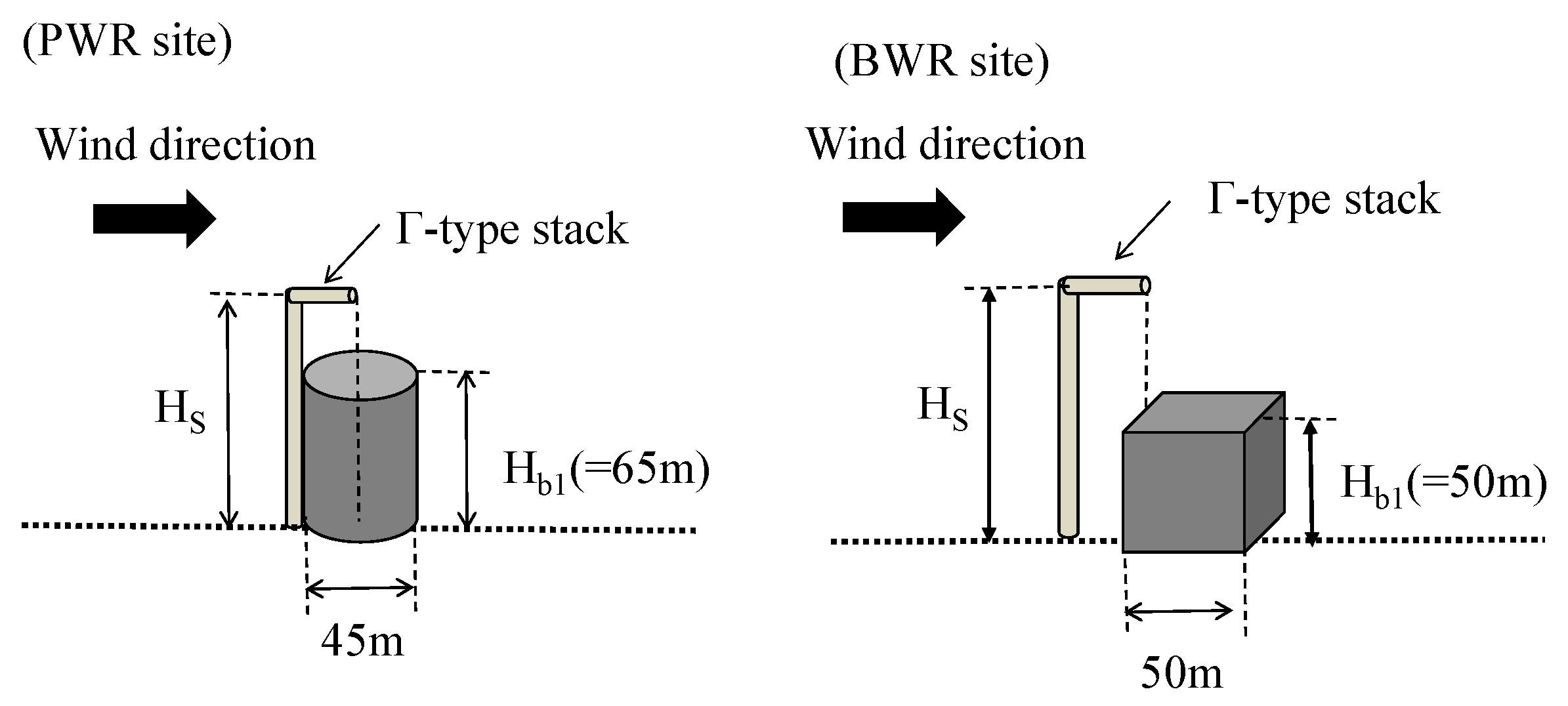
In the wind tunnel experiments, a boiling-water reactor (BWR) site and pressurized-water reactor (PWR) site were assumed. The geometry of the reactor and the stack locations in the model PWR and BWR sites are shown in
Figure 1. The reactor at the PWR site was modeled as a circular cylinder with a height of 65 m and a diameter of 45 m, and the source heights were 65 m and 150 m for normal- and accidental-release conditions, respectively. The reactor at the BWR site was modeled as a 50 m cube and the source heights were 120 m and 180 m for normal- and accidental-release conditions, respectively. Note that the source height is defined as a stack height plus plume rise caused by momentum of the exhaust gas. The temperature of the exhaust gas is assumed to be equal to the atmosphere temperature. The normal reactor size and normal stack height in the existing sites in Japan were reproduced. The Reynolds number based on the building height is 13,000 at the PWR site and 10,000 at the BWR sites, which is much smaller than the Reynolds number in real atmospheric flows. However, Catro and Robins [
10] and Snyder and Castro [
11] suggest that the Reynolds number dependency for flows over sharp-edged obstacles such as the reactor at the BWR site is weak. On the other hand, a flow region behind two-dimensional circular cylinder strongly depends on the Reynolds number, but the wake behind finite cylinders of small aspect ratio of cylinder height L to diameter D (L/D = 1–2) like the PWR site is symmetric and the Reynolds number dependency for flows is weak [
12].
At real sites, the complicated terrain and numerous existing buildings generate stronger turbulence and strongly affect the effective stack height. In the present experiments, since only the reactor building was modeled as the existing building, the turbulence generated by an additional structure strongly affected the effective stack height. Therefore, the additional structure has a much greater impact on the effective stack height than those at real sites.
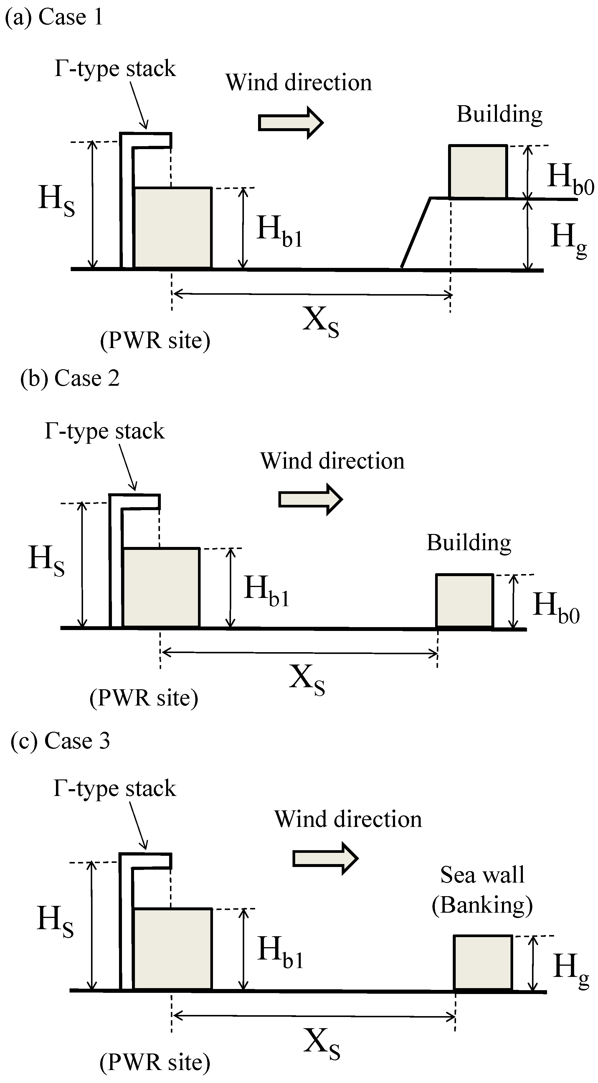
Three types of layout were assumed when investigating the effect of the additional structure. In Case 1, the building is built on a hill as shown in
Figure 2a. Here, Hs is the source height, Xs is the streamwise distance between the source and the building, Hg is the hill height and Hb0 is the height of the additional building. In Case 2, the building is built on land with the same altitude as the reactor building as shown in
Figure 2b. In Case 1 and Case 2, the additional building is reproduced as a square block. In Case 3, a sea wall or banking is built on land with the same altitude, and such a structure is reproduced as a long horizontal block as shown in
Figure 2c. In Case 3, Hg is the height of the sea wall or banking. All the experimental conditions in this study are listed in
Table 1. Note that a negative value of Xs indicates that the additional structure is built upwind of the stack.
The relative change in the effective stack height (
) is defined as
where
is the effective stack height, subscript A represents the value considering the additional structure and subscript B represents the value without the additional structure. When the relative decrease in the effective stack height attributed to the additional structure was more than 10%, it was estimated that the additional structure affects the effective stack height to some degree. This criterion indicates that the uncertainty of the wind-tunnel experiments is approximately 10%, as shown in the guide for safety analysis in Japan [
1]. The effective stack height (He) is used in the safety analysis of atmospheric gas dispersion for nuclear facilities in Japan. Note that the increase in
contributes to a decrease in the relative dose on the ground estimated by the empirically formulated plume model. Hence, only the decrease in
with increasing relative dose is discussed in this study.
3. Results
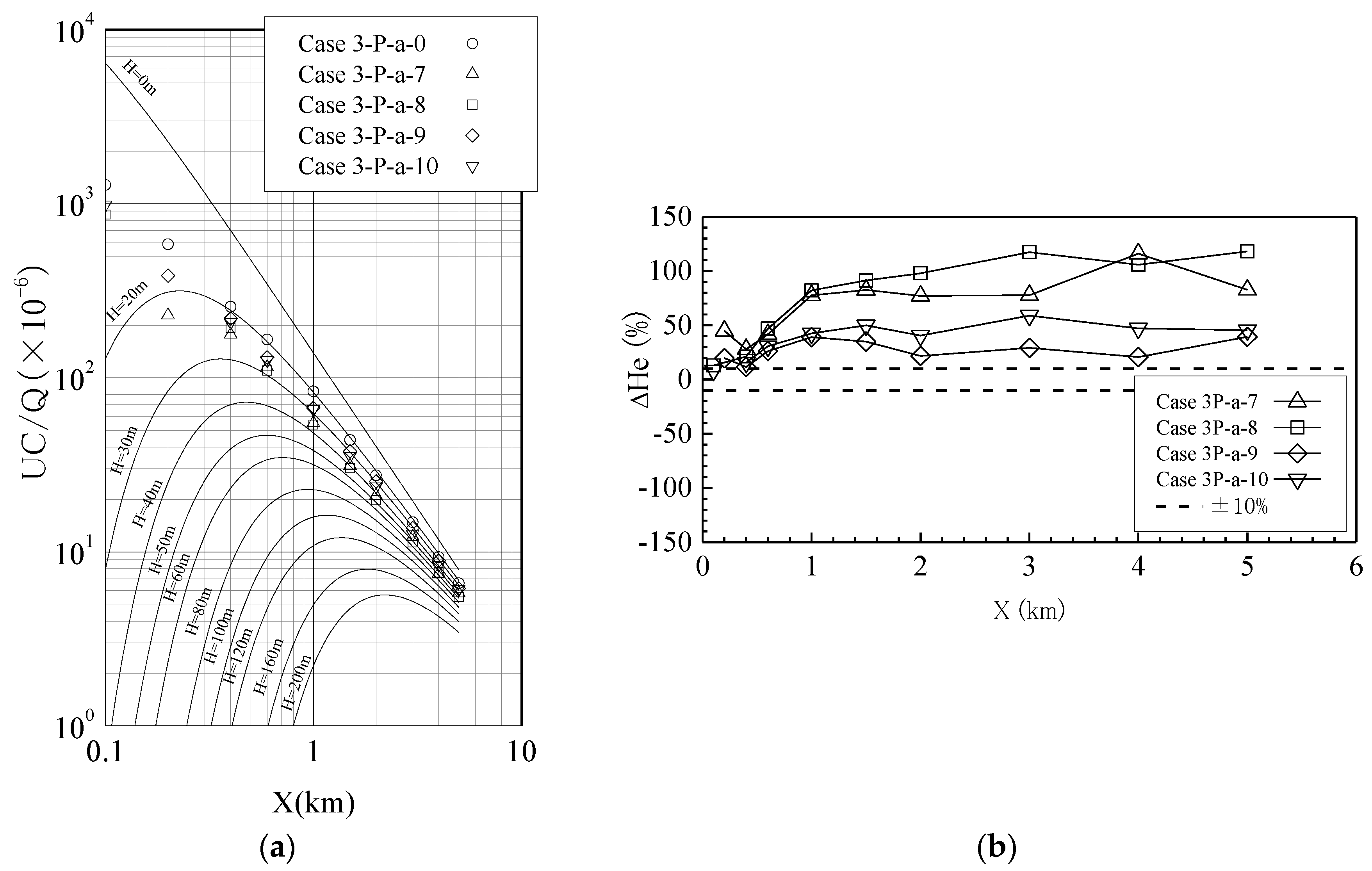
Figure 3 shows examples of the results of wind-tunnel experiments for the PWR site (Cases 3P-a-0, 3P-a-7, 3P-a-8, 3P-a-9 and 3P-a-10). The concentration, C, was normalized by the free stream velocity (U = 3.0 m/s) and the source strength, Q. Under these conditions, an additional structure (the sea wall or banking) with a height of 20 or 30 m was built 100 or 200 m downwind of the stack. The curves in
Figure 3a represent the surface concentrations obtained under the flat-plate condition at various stack heights (H = 0–200 m). Using the results shown in
Figure 3a, the effective stack heights were evaluated (1) by the comparison of the surface concentrations along the plume axis under the reactor building conditions with those under the flat-plate condition and (2) for the smallest corresponding stack heights under the flat-plate condition.
Since the ground concentration in the base case (Case 3-P-a-0) without an additional structure has a peak value at X = 0.1 km, the gas reaches the ground near the source and disperses downwind. When an additional structure is built, the gas dispersion near the ground is enhanced by the structure and the ground concentration decreases irrespective of the geometry of the additional structure. The decrease in the ground concentration increases the effective stack height, as shown in
Figure 3b, and
in all the cases. This indicates that the effect of the additional structure is small when it is evaluated by the present criterion.
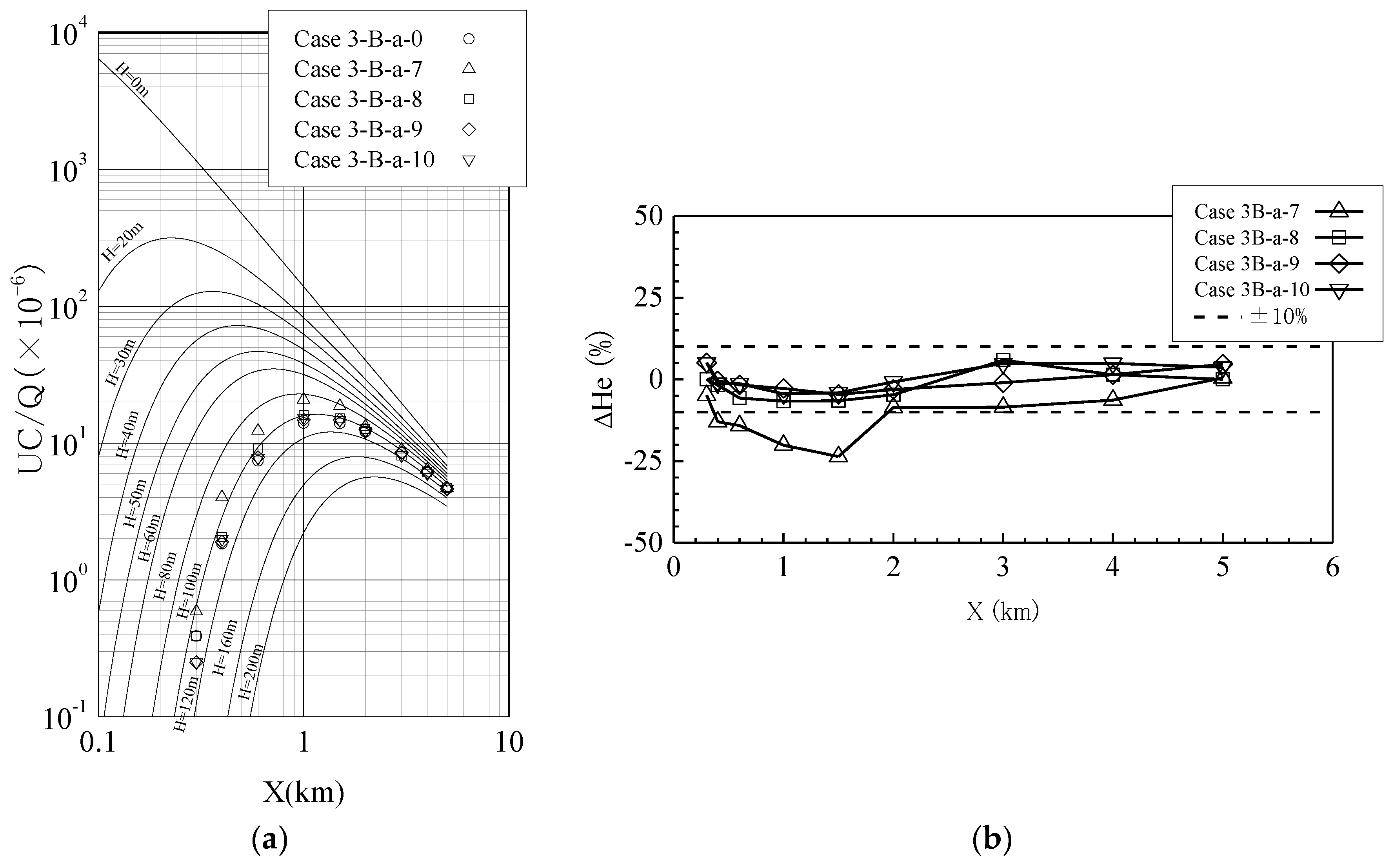
Figure 4 shows examples of the results of wind-tunnel experiments for the BWR site (Cases 3B-a-0, 3B-a-7, 3B-a-8, 3B-a-9 and 3B-a-10). Under these conditions, an additional structure (sea wall or banking) with a height of 20 or 30 m was built 100 or 200 m downwind of the stack. Since the source height (H = 120 m) in the BWR site is larger than that in the PWR site (H = 65 m), the ground concentration has a peak value at X = 1 km and monotonically decreases downwind. As contrasted with the PWR site, the ground concentration is increased by the additional structure because the turbulence generated by the additional structure affects the dispersal of the gas above the ground. Therefore, the effective stack height tends to be decreased as shown in
Figure 4b. When the additional structure has a height of 10 m (Cases 3B-a-9 and 3B-a-10),
. On the other hand, when an additional structure with a height of 20 m is built, the location of the additional structure strongly affects the effective height. For Case 3B-a-8 (Xs = 200 m)
, but
for Case 3B-a-7 (Xs = 100 m).
As discussed above, the source height (Hs) is an important parameter when considering the effects of additional structure on the effective height.
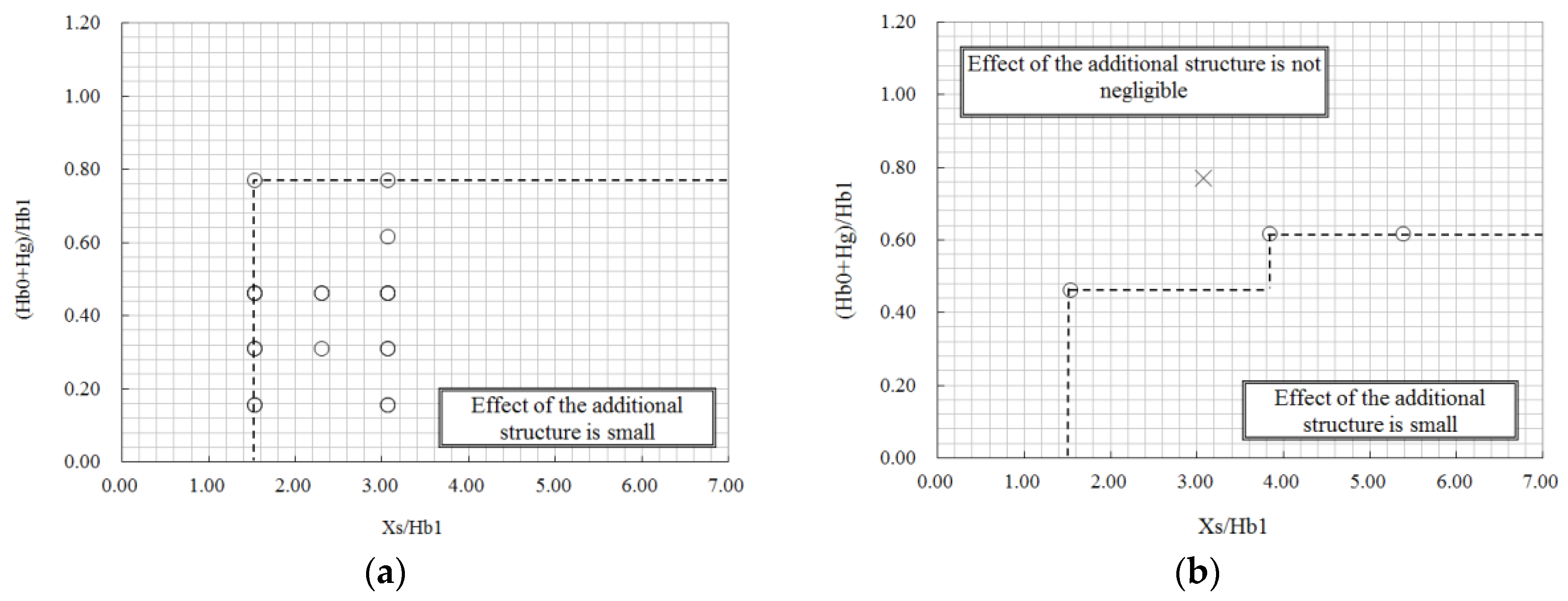
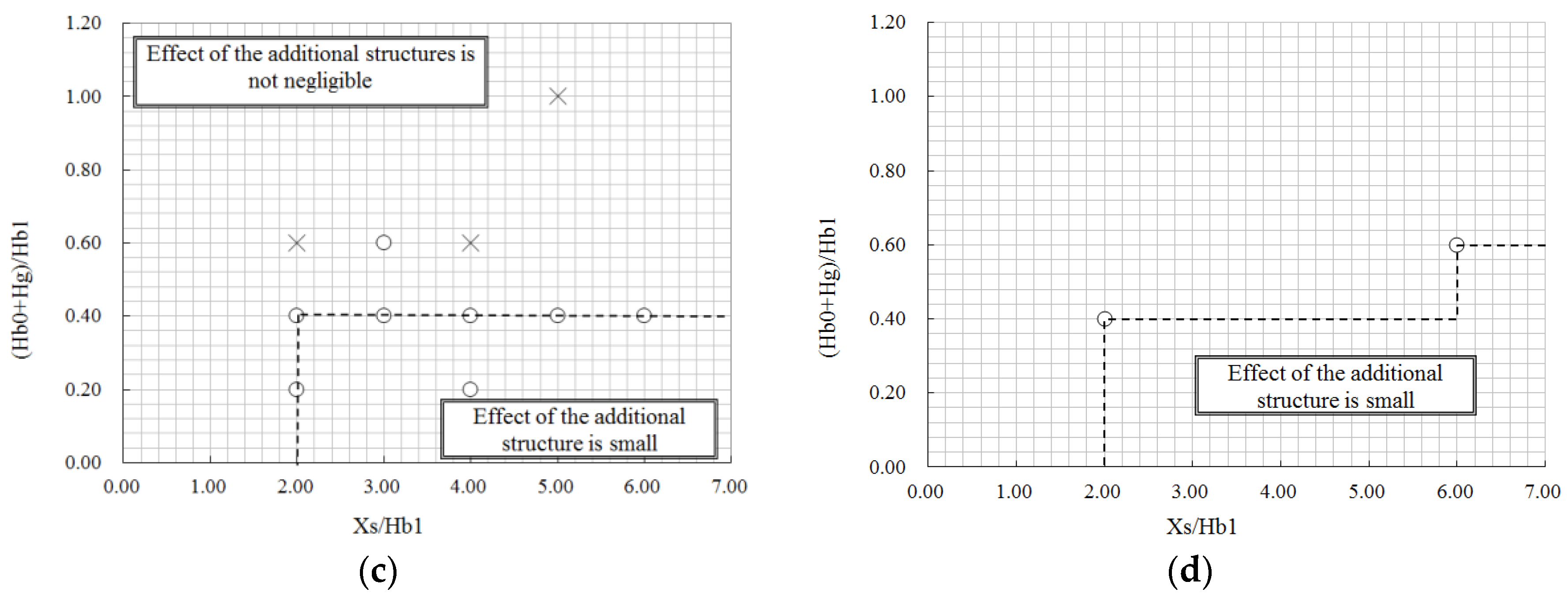
Figure 5 shows the effect of an additional structure on the effective stack height for four source heights (Hs/Hb1= 1.0, 2.3, 2.4 and 3.6). The distance between the source and the additional structure, Xs, is normalized by the reactor height Hb1, which mostly affects the turbulence at these sites. Also, the height of the additional building, Hb including the hill, sea wall or banking height Hg is also normalized by Hb1. The circles in
Figure 5 show the experimental results for which
is larger than
. That is, the effect of the additional structure is small when it is evaluated by the present criterion. The crosses in
Figure 5 show the experimental results for which
is smaller than −10%. As shown in
Figure 4, when the distance between the source stack and the additional structure decreases, or when the height of the additional structure becomes increase, the structure has a larger effect on effective stack height. Therefore, in the lower right region enclosed by the dashed lines, the effect of the additional structure is small.
When the stack is integrated with the nuclear reactor building and the source height is equivalent to the reactor building height (
Figure 5a), the additional structure enhances both the vertical and horizontal gas dispersion widths and decreases the ground gas concentration, meaning that the additional structure does not decrease the effective stack height.
The source height in the case of normal release at the PWR site and the cases of both accidental and normal releases at the BWR site is larger than the reactor height. Under these conditions, there are cases for which the relative decrease in the effective stack height is over 10%. Since the values of Hs/Hb1 are fixed (Hs/Hb1 = 2.31, 2.4 and 3.6) in the present wind-tunnel experiments, the effect of the effective stack height can not be easily determined for the different values of Hs/Hb1. To determine the effect of the effective stack height at an arbitrary source height, the effect of the additional structure is reconsidered as follows.
When the source height is 2.5 times larger than the reactor height, it was previously confirmed that the effect of the building on the effective stack height is small [
5]. In the present experiments, the same result was obtained. Under the condition when Hs/Hb1 = 3.6, as shown in
Figure 5d, both the reactor building and the additional structure does not decrease the effective stack height.
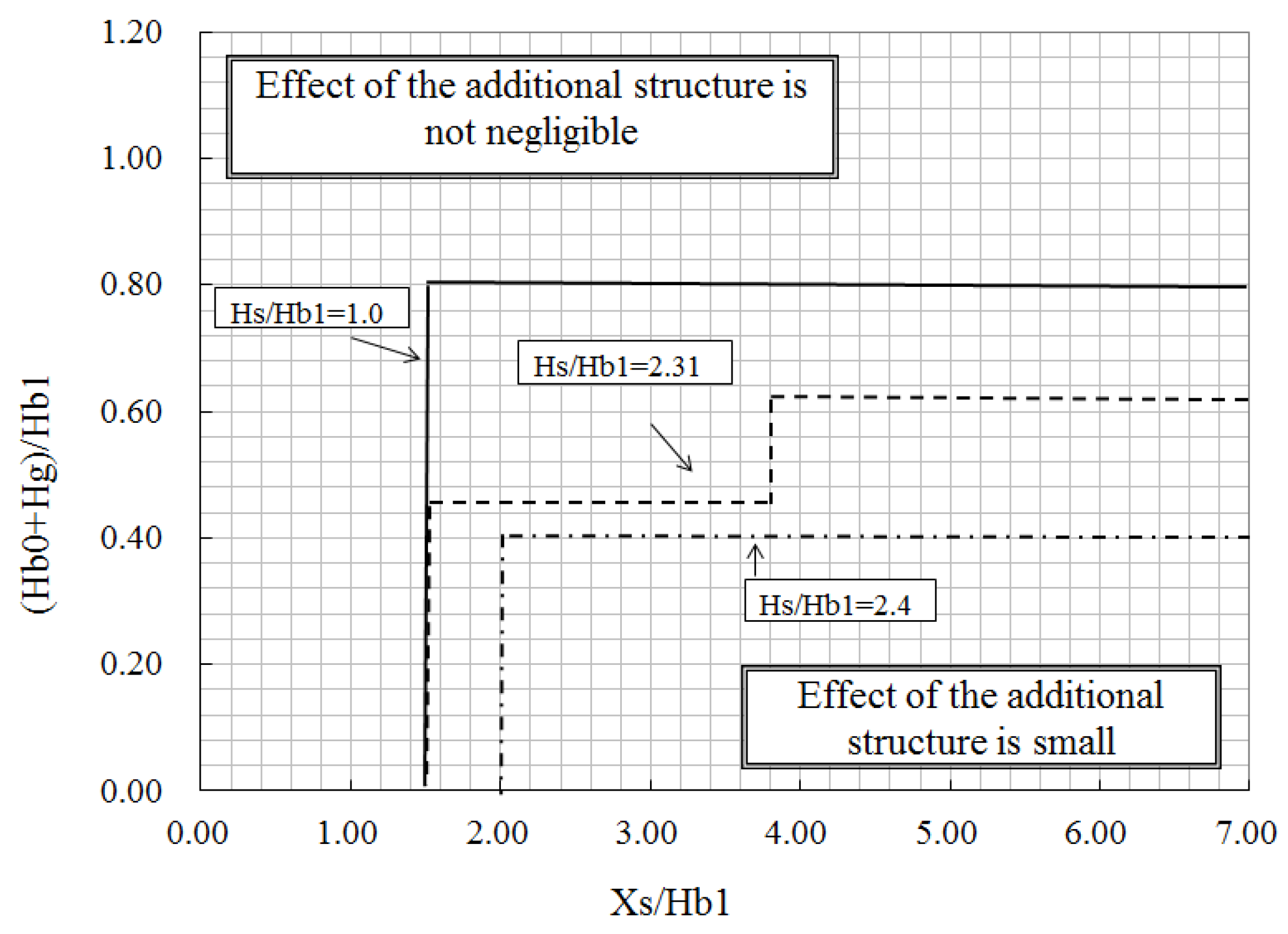
When Hs/Hb1 < 2.5, the additional structure may affect the effective stack height.
Figure 6 shows the graph obtained by superimposing
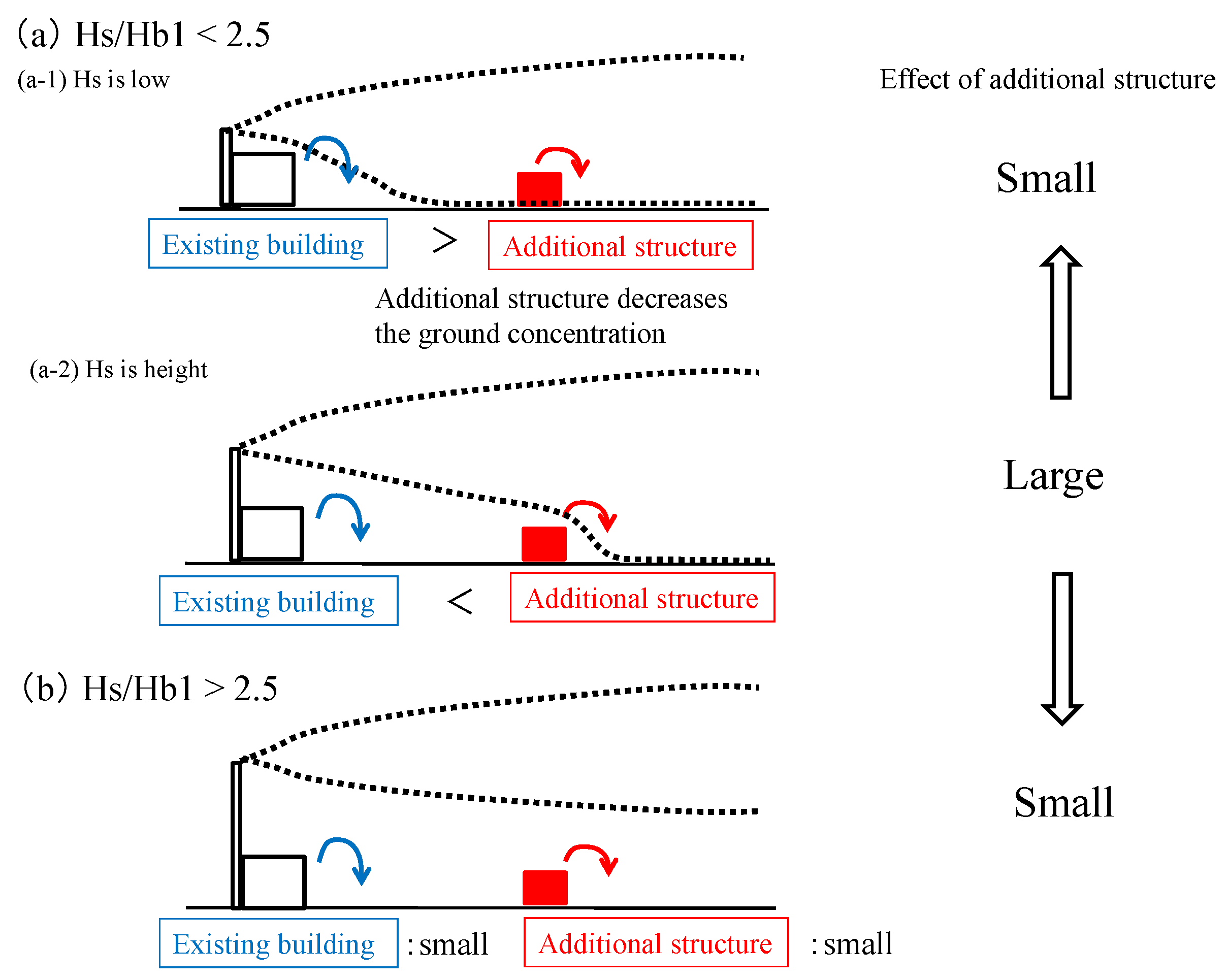
Figure 5a–c to show the results for Hs/Hb1 < 2.5. As Hs/Hb1 decreases, the area in which the “effect of the additional structure is not negligible” increases. That is, as the source height decreases, the reactor building more strongly affects the gas dispersion and the effect of the additional structure on the gas dispersion becomes relatively smaller as shown in
Figure 7a-1. In contrast, as the source height increases, the effect of the additional structure on the gas dispersion becomes relatively larger as shown in
Figure 7a-2. However, the additional structure has most impact on the effective stack height when Hs/Hb1 = 2.4 because the effect of the building on the effective stack height is small under Hs/Hb1 > 2.5 [
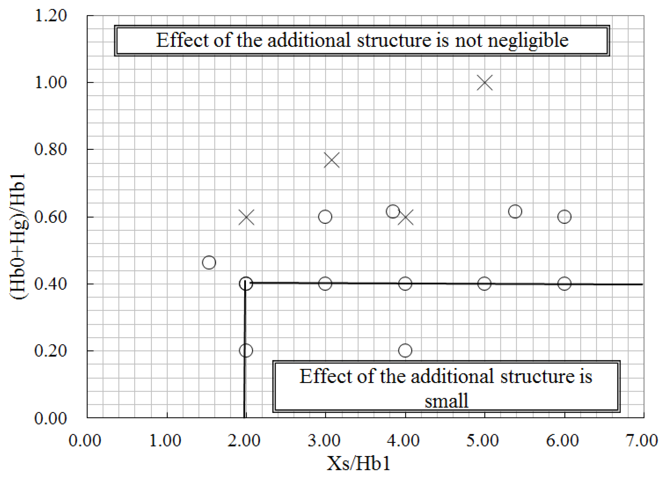
5]. Since the area for Hs/Hb1 = 2.4 is smallest when Hs/Hb1 < 2.5, the smallest area should be applied to ensure a safety margin for Hs/Hb1 < 2.5. In summary, as shown in
Figure 8, the effect of the additional structure on the effective stack height is small when the distance between the additional structure and the source is more than twice the reactor building height and the height of the additional structure less than 0.4 times the reactor building height.


