
Roughening Conjugated Polymer Surface for Enhancing the Charge Collection Efficiency of Sequentially Deposited Polymer/Fullerene Photovoltaics


Abstract
:
1. Introduction
2. Experimental Section
2.1. Device Fabrication
2.2. Measurement
3. Results and Discussion


| Film Description | Vol% of 1-CN in CB | Increased Surface Area * (× 104 nm2) | RMS (nm) |
|---|---|---|---|
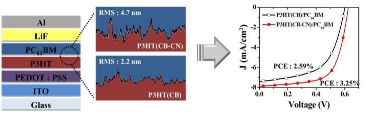
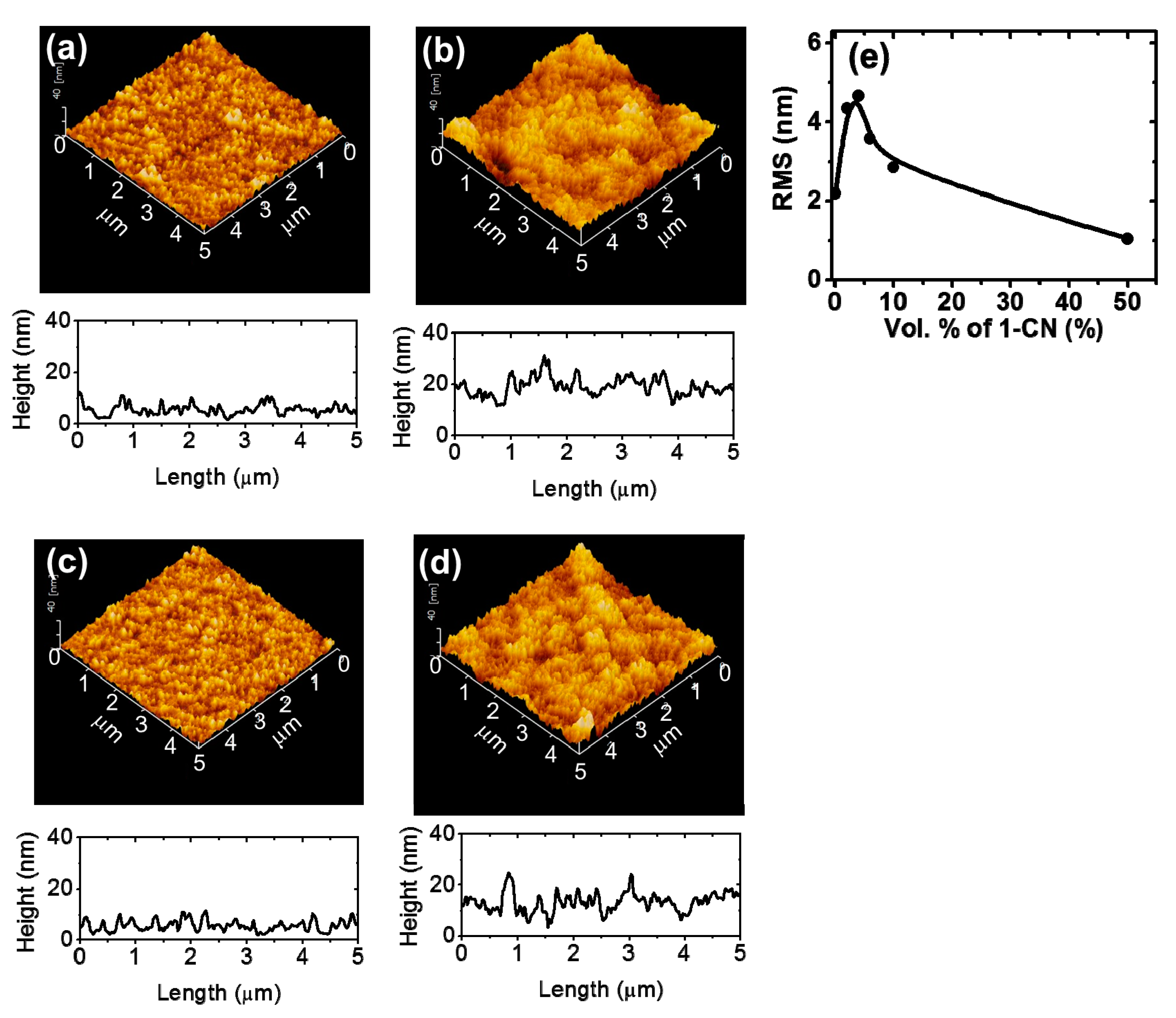
| As prepared P3HT | 0 | 7 | 2.2 |
| 2 | 12 | 4.4 | |
| 4 | 13 | 4.7 | |
| 6 | 11 | 3.6 | |
| 10 | 12 | 2.9 | |
| 50 | 4 | 1.0 | |
| P3HT after removal of PC61BM from the P3HT/PC61BM film | 0 | 9 | 2.1 |
| 2 | 20 | 4.2 |

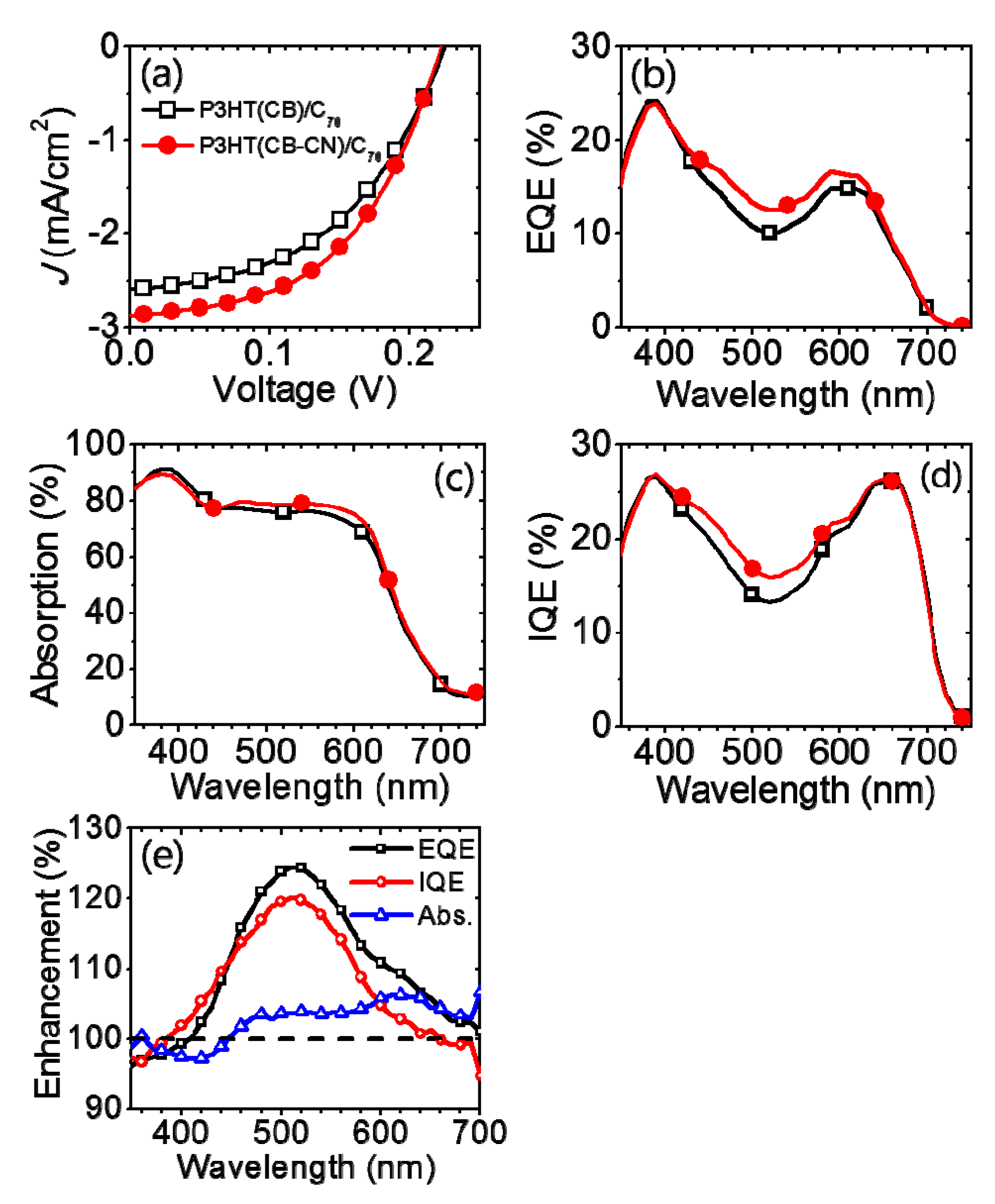
| Active Layer | VOC (V) | JSC (mA/cm2) | FF | PCE (%) |
|---|---|---|---|---|
| P3HT(CB)/C70 | 0.22 | 2.59 | 0.48 | 0.28 |
| P3HT(CB-CN)/C70 | 0.22 | 2.87 | 0.50 | 0.32 |

| Active Layer | VOC (V) | JSC (mA/cm2) | FF | PCE (Avg.) (%) | PCE (Max.) (%) |
|---|---|---|---|---|---|
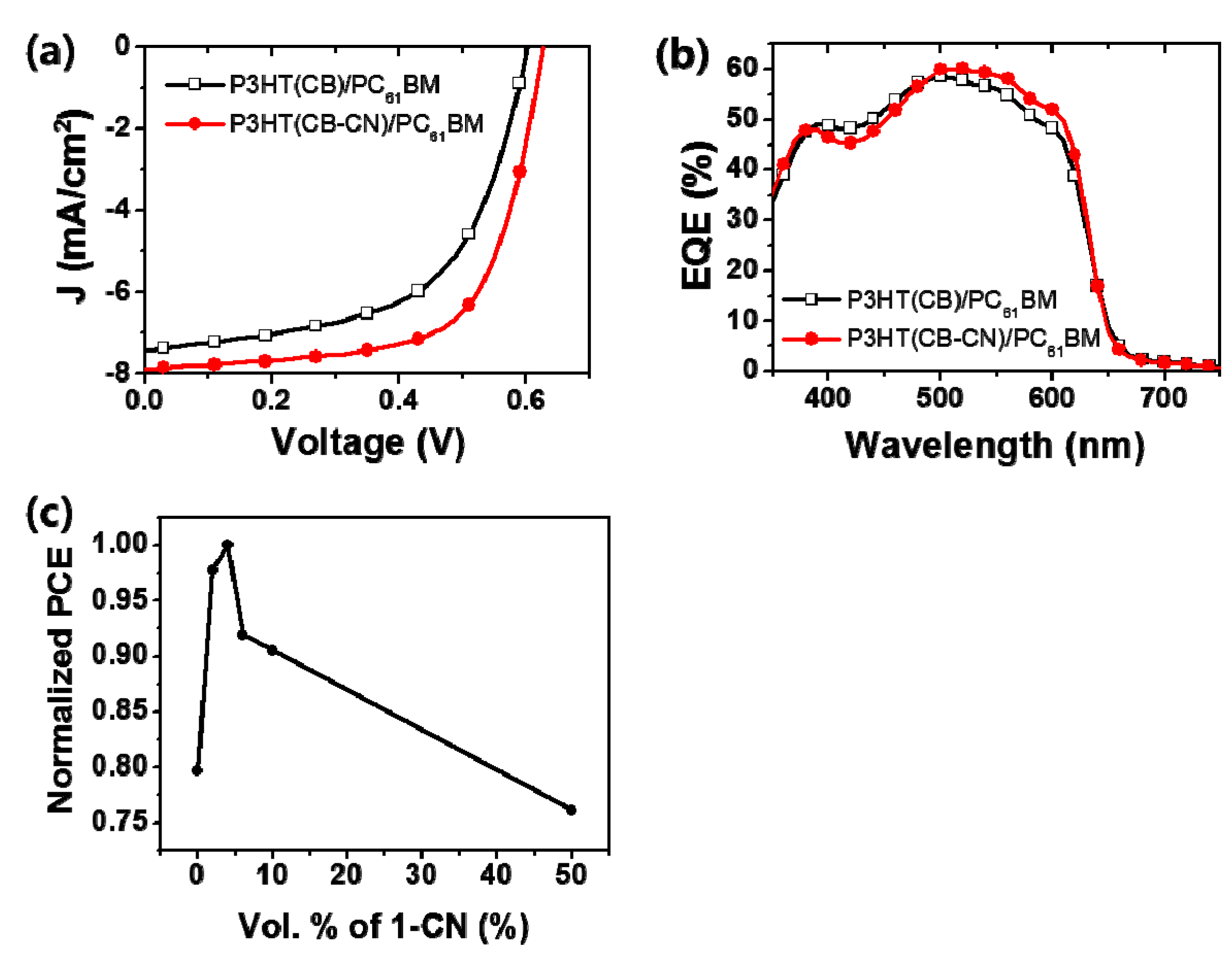
| P3HT(CB)/PC61BM | 0.60 | 7.43 | 0.58 | 2.32 ± 0.33 | 2.59 |
| P3HT(CB-CN)/PC61BM | 0.63 | 7.89 | 0.66 | 3.22 ± 0.025 | 3.25 |
4. Conclusions
Acknowledgments
Author Contributions
Conflicts of Interest
References
- Yu, G.; Gao, J.; Hummelen, J.C.; Wudl, F.; Heeger, A.J. Polymer photovoltaic cells: Enhanced efficiencies via a network of internal donor–acceptor heterojunctions. Science 1995, 270, 1789–1790. [Google Scholar] [CrossRef]
- Kim, K.; Liu, J.; Namboothiry, M.A.; Carroll, D.L. Roles of donor and acceptor nanodomainsin 6% efficient thermally annealed polymer photovoltaics. Appl. Phys. Lett. 2007, 90, 163511. [Google Scholar] [CrossRef]
- Lee, J.K.; Ma, W.L.; Brabec, C.J.; Yuen, J.; Moon, J.S.; Kim, J.Y.; Lee, K.; Bazan, G.C.; Heeger, A.J. Processing additives for improved efficiency from bulk heterojunction solar cells. J. Am. Chem. Soc. 2008, 130, 3619–3623. [Google Scholar] [CrossRef] [PubMed]
- Ayzner, A.L.; Tassone, C.J.; Tolbert, S.H.; Schwartz, B.J. Reappraising the need for bulk heterojunctions in polymer—Fullerene photovoltaics: The role of carrier transport in all-solution-processed P3HT/PCBM bilayer solar cells. J. Phys. Chem. 2009, 113, 20050–20060. [Google Scholar] [CrossRef]
- Lee, K.H.; Schwenn, P.E.; Smith, A.R.; Cavaye, H.; Shaw, P.E.; James, M.; Krueger, K.B.; Gentle, I.R.; Meredith, P.; Burn, P.L. Morphology of all-solution-processed “bilayer” organic solar cells. Adv. Mater. 2011, 23, 766–770. [Google Scholar] [CrossRef] [PubMed]
- Osaka, I.; McCullough, D. Advances in molecular design and synthesis of regioregular polythiophenes. Acc. Chem. Res. 2008, 41, 1202–1214. [Google Scholar] [CrossRef] [PubMed]
- Marrocchi, A.; Lanari, D.; Facchetti, A.; Vaccaro, L. Poly(3-hexylthiophene): Synthetic methodologies and properties in bulk heterojunction solar cells. Energy Environ. Sci. 2012, 5, 8457–8474. [Google Scholar] [CrossRef]
- Vohra, V.; Arrighetti, G.; Barba, L.; Higashimine, K.; Porzio, W.; Murata, H. Enhanced vertical concentration gradient in rubbed P3HT:PCBM graded bilayer solar cells. J. Phys. Chem. Lett. 2012, 3, 1820–1823. [Google Scholar] [CrossRef]
- Ayzner, A.L.; Doan, S.C.; TremoletdeVillers, B.; Schwartz, B.J. Ultrafast studies of exciton migration andpolaronformation in sequentially solution-processed conjugated polymer/fullerene quasi-bilayer photovoltaics. J. Phys. Chem. Lett. 2012, 3, 2281–2287. [Google Scholar] [CrossRef]
- Zhang, G.; Huber, R.C.; Ferreira, A.S.; Boyd, S.D.; Luscombe, C.K.; Tolbert, S.H.; Schwartz, B.J. Crystallinity effects in sequentially processed and blend-cast bulk-heterojunction polymer/fullerene photovoltaics. J. Phys. Chem. 2014, 118, 18424–18435. [Google Scholar] [CrossRef]
- Lee, K.H.; Zhang, Y.; Burn, P.L.; Gentle, I.R.; James, M.; Nelson, A.; Meredith, P. Correlation of diffusion and performance in sequentially processed P3HT/PCBM heterojunction films by time-resolvedneutron reflectometry. J. Mater. Chem. 2013, 1, 2593–2598. [Google Scholar]
- Hawks, S.A.; Aguirre, J.C.; Schelhas, L.T.; Thompson, R.J.; Huber, R.C.; Ferreira, A.S.; Zhang, G.; Herzing, A.A.; Tolbert, S.H.; Schwartz, B.J. Comparing matched polymer:Fullerene solar cells made by solution-sequential processing and traditional blend casting: Nanoscale structure and device performance. J. Phys. Chem. 2014, 118, 17413–17425. [Google Scholar] [CrossRef]
- Clulow, A.J.; Tao, C.; Lee, K.H.; Velusamy, M.; McEwan, J.A.; Shaw, P.E.; Yamada, N.L.; James, M.; Burn, P.L.; Gentle, I.R.; et al. Time-resolved neutron reflectometry and photovoltaic device studies on sequentially deposited PCDTBT-Fullerene layers. Langmuir 2014, 38, 11474–11484. [Google Scholar] [CrossRef] [PubMed]
- Nardes, A.M.; Ayzner, A.L.; Hammond, S.R.; Ferguson, A.J.; Schwartz, B.J.; Kopidakis, N. Photoinduced charge carrier generation and decay in sequentially deposited polymer/fullerene layers: Bulk heterojunction vs. planar interface. J. Phys. Chem. 2012, 116, 7293–7305. [Google Scholar] [CrossRef]
- Gadisa, A.; Tumbleston, J.R.; Ko, D.-H.; Aryal, M.; Lopez, R.; Samulski, E.T. The role of solvent and morphology on miscibility of methanofullerene and poly(3-hexylthiophene). Thin Solid Films 2012, 520, 5466–5471. [Google Scholar] [CrossRef]
- Ramanathan, M.; MichaelKilbey, S., II; Ji, Q.; Hill, J.P.; Ariga, K. Materials self-assembly and fabrication in confined spaces. J. Mater. Chem. 2012, 22, 10389–10405. [Google Scholar] [CrossRef]
- Xiong, K.; Hou, L.; Wu, M.; Huo, Y.; Mo, W.; Yuan, Y.; Sun, S.; Xu, W.; Wang, E. From spin coating to doctor blading: A systematic study on the photovoltaic performance of anisoindigo-based polymer. Sol. Energy Mater. Sol. Cells 2015, 132, 252–259. [Google Scholar] [CrossRef]
- Guo, S.; Herzig, E.M.; Naumann, A.; Tainter, G.; Perlich, J.; Müller-Buschbaum, P. Influence of solvent and solvent additive on the morphology of PTB7 films probed via X-ray scattering. J. Phys. Chem. 2013, 118, 344–350. [Google Scholar] [CrossRef] [PubMed]
- Beaujuge, P.M.; Fréchet, J.M. Molecular design and ordering effects in π-functional materials for transistor and solar cell applications. J. Am. Chem. Soc. 2011, 133, 20009–20029. [Google Scholar] [CrossRef] [PubMed]
- Hoven, C.V.; Dang, X.D.; Coffin, R.C.; Peet, J.; Nguyen, T.Q.; Bazan, G.C. Improved performance of polymer bulk heterojunction solar cells through the reduction of phase separation via solvent additives. Adv. Mater. 2010, 22, E63–E66. [Google Scholar] [CrossRef] [PubMed]
- Wu, M.-C.; Lin, Y.-Y.; Chen, S.; Liao, H.-C.; Wu, Y.-J.; Chen, C.-W.; Chen, Y.-F.; Su, W.-F. Enhancing light absorption and carrier transport of P3HT by doping multi-wall carbon nanotubes. Chem. Phys. Lett. 2009, 468, 64–68. [Google Scholar] [CrossRef]
- Vanlaeke, P.; Swinnen, A.; Haeldermans, I.; Vanhoyland, G.; Aernouts, T.; Cheyns, D.; Deibel, C.; D’Haen, J.; Heremans, P.; Poortmans, J. P3HT/PCBM bulk heterojunction solar cells: Relation between morphology and electro-optical characteristics. Sol. Energy Mater. Sol. Cells 2006, 90, 2150–2158. [Google Scholar] [CrossRef]
- Salim, T.; Wong, L.H.; Bräuer, B.; Kukreja, R.; Foo, Y.L.; Bao, Z.; Lam, Y.M. Solvent additives and their effects on blend morphologies of bulk heterojunctions. J. Mater. Chem. 2011, 21, 242–250. [Google Scholar] [CrossRef]
- Sakai, J.; Taima, T.; Yamanari, T.; Yoshida, Y.; Fujii, A.; Ozaki, M. Pentacene:Fullerene multilayer-heterojunction organic photovoltaic cells fabricated by alternating evaporation method. Jpn. J. Appl. Phys. 2010, 49, 032301. [Google Scholar] [CrossRef]
- Heremans, P.; Cheyns, D.; Rand, B.P. Strategies for increasing the efficiency of heterojunction organic solar cells: Material selection and device architecture. Acc. Chem. Res. 2009, 42, 1740–1747. [Google Scholar] [CrossRef] [PubMed]
- Slota, J.E.; He, X.; Huck, W.T. Controlling nanoscale morphology in polymer photovoltaic devices. Nano Today 2010, 5, 231–242. [Google Scholar] [CrossRef]
- Erb, T.; Zhokhavets, U.; Gobsch, G.; Raleva, S.; Stühn, B.; Schilinsky, P.; Waldauf, C.; Brabec, C.J. Correlation between structural and optical properties of composite polymer/fullerene films for organic solar cells. Adv. Funct. Mater. 2005, 15, 1193–1196. [Google Scholar] [CrossRef]
© 2015 by the authors; licensee MDPI, Basel, Switzerland. This article is an open access article distributed under the terms and conditions of the Creative Commons Attribution license (http://creativecommons.org/licenses/by/4.0/).
Share and Cite
Jang, Y.; Seo, J.-W.; Seok, J.; Lee, J.-Y.; Kim, K. Roughening Conjugated Polymer Surface for Enhancing the Charge Collection Efficiency of Sequentially Deposited Polymer/Fullerene Photovoltaics. Polymers 2015, 7, 1497-1509. https://doi.org/10.3390/polym7081466
Jang Y, Seo J-W, Seok J, Lee J-Y, Kim K. Roughening Conjugated Polymer Surface for Enhancing the Charge Collection Efficiency of Sequentially Deposited Polymer/Fullerene Photovoltaics. Polymers. 2015; 7(8):1497-1509. https://doi.org/10.3390/polym7081466
Chicago/Turabian StyleJang, Yoonhee, Ji-Won Seo, Jeesoo Seok, Jung-Yong Lee, and Kyungkon Kim. 2015. "Roughening Conjugated Polymer Surface for Enhancing the Charge Collection Efficiency of Sequentially Deposited Polymer/Fullerene Photovoltaics" Polymers 7, no. 8: 1497-1509. https://doi.org/10.3390/polym7081466