1. Introduction
Masonry is a historical construction material and has served as the first choice of people for many centuries. Pleasing aesthetics with good sound and heat insulation properties are some of the inherent advantages of masonry. Local availability of masonry raw materials and having lower cost of manufacturing has made it a popular construction material. Even in the recent times masonry structures are higher in number than concrete, steel and wooden structures [
1]. However, historically unreinforced masonry (URM) structures have suffered extensive damage during earthquakes. Therefore, to increase the seismic capacity of low earthquake-resistant masonry structures is one of the key issues for earthquake disaster mitigation and for reduction of casualties. Seismic retrofitting reduces not only casualties and damage to buildings during earthquakes, but also the costs of first aid activities, rescue, rubble removal and permanent residential reconstruction to help and support re-establishment of daily life [
2]. URM buildings can fail due to deficient strength of walls when loaded in in-plane and out-of-plane directions [
3]. Seismic capacity of URM buildings depends on the ability of in-plane walls to effectively transfer lateral forces to the foundations [
4,
5].
Failure of in-plane walls occurs due to formation of diagonal shear cracks, by sliding of a portion of the wall generally along a bed joint (sliding shear deformation), by rocking about the wall toe or by crushing of the wall toe [
6]. URM structures are much weaker in out-of-plane direction as compared to in-plane direction and final collapse of masonry buildings is due to out-of-plane failure of URM walls [
7].
In order to avoid diagonal shear failure and out-of-plane failure of URM walls, different retrofitting procedures have been adopted by different researchers [
8]. Some of the retrofitting methods include the seismic retrofit of URM walls using externally-bonded or near surface mounted Fiber Reinforced Polymer (FRP) laminates, bars and fabrics. Experiments on various patterns and layouts of FRP have validated that FRP can significantly increase in-plane and out-of-plane strength of URM walls [
7,
9,
10,
11,
12,
13,
14,
15,
16,
17,
18,
19,
20,
21,
22]. Higher strength to weight ratio, ease of application and corrosion resistance are some of well-known advantages of FRP retrofitting technique over conventional retrofitting methods. On the other side, FRP is a costly material and exhibits a brittle failure [
11,
14,
23].
In addition to aforementioned retrofitting methods, Mayorca and Meguro [
24] proposed polypropylene band (PP-band) mesh retrofitting technique. PP-band is normally used for packing and also available worldwide. PP-band is a low cost material with large deformation capacity [
25]. A mesh of PP-band can be applied to URM structures to hold the masonry components into a single unit and to prevent the collapse of masonry structures. After carrying out a series of experiments ranging from small-scale model to full-scale masonry house, it was found that PP-band retrofitted walls can withstand much stronger input ground motion without collapse [
2,
24,
26,
27,
28,
29,
30].
2. Research Objectives
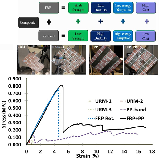
In this study, a new composite retrofitting material is proposed, which consists of FRP and PP-band. This composite retrofitting technique can increase the shear strength and bending strength of URM walls and can serve satisfactorily to hold the structural system by providing sufficient deformation capacity. FRP is a brittle material having ultimate tensile strain ranging from only 2% to 4% [
31]. PP-band cannot increase initial strength, but it can increase deformation capacity and energy dissipation capacity of masonry wall systems [
30]. In order to get holding effect, if FRP is used for brick masonry, then it is required to apply FRP on whole wall surface, which will tremendously increase the retrofitting cost and still the ductile failure of masonry wall system is not guaranteed. On the other hand, PP-band mesh is not only a fairly ductile and deformable, but can also be wrapped around to the whole wall system, because of very low retrofitting cost.
Main objective of this study was to investigate the effect of PP-band and FRP composite on increase in strength and deformation capacity of masonry wall panels. In order to achieve aforementioned objective, diagonal compression tests and three-point bending tests using 1/4-scale retrofitted and non-retrofitted masonry panels were carried out.
3. Experimental Results
Experiments were conducted in three main phases, material test, diagonal compression tests and out-of-plane bending tests on 1/4-scale retrofitted and non-retrofitted masonry panels.
3.1. Diagonal Compression Tests Results
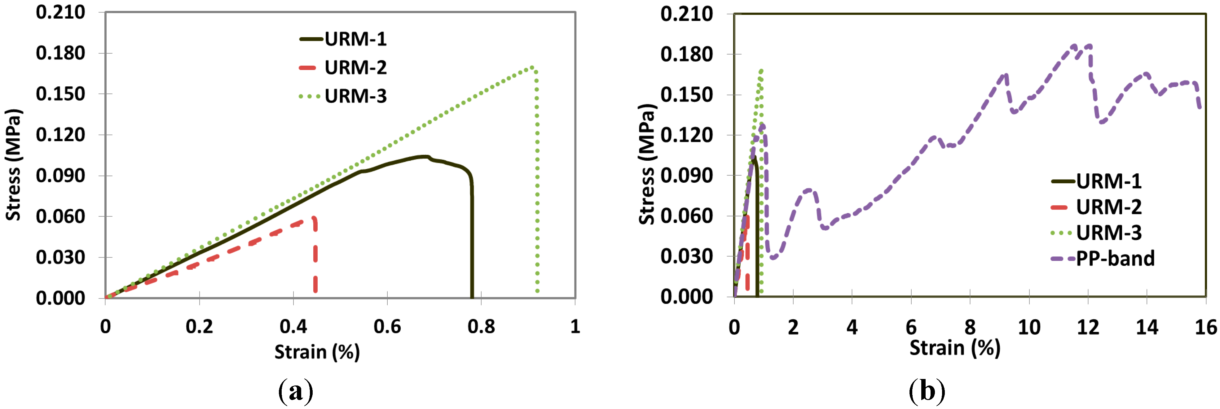
Figure 1a shows the stress-strain of three non-retrofitted masonry panels, which are abbreviated as URM-1, URM-2 and URM-3. All of the URM masonry panels have shown different peak strength values. Stress-strain curve of PP-band retrofitted masonry panel along with URM masonry panels is shown in
Figure 1b. PP-band retrofitted panel has shown same initial stiffness as that of URM’s, with a peak stress value of 0.126 MPa. After the initial peak stress, there was sudden drop in peak value due to failure of masonry panel, but as the applied load further increases PP-band comes into action and restrains the further movement of failed masonry. This phenomenon can be seen by increase in load carrying capacity of panel after the strain value of 1.5%. There are some rises and falls in load carrying capacity of masonry panel, which is due to subsequent failure of masonry and PP-band restraining action. After the strain value of 8%, the load carrying capacity has even increased from the initial peak load and keeps on increasing up to 12.1% strain. Beyond 12.1%, bricks and mortar started crushing due to very high compressive displacements.
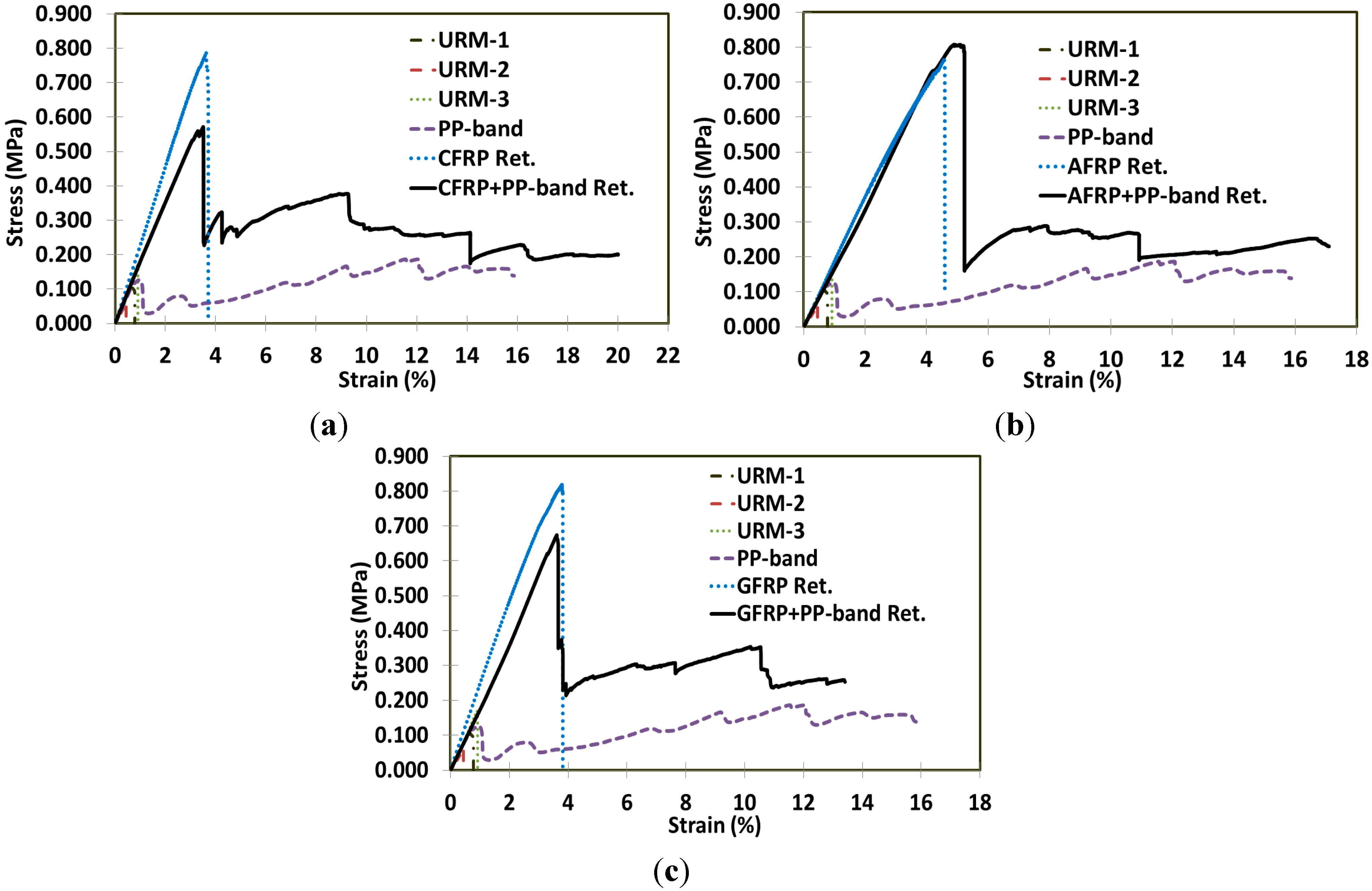
To understand behavior of retrofitted and non-retrofitted masonry panels under diagonal compression loading, stress-strain curves of non-retrofitted are presented along with retrofitted masonry panels in
Figure 2.
Figure 2a shows the stress-strain curves of Carbon Fiber Reinforced Polymer (CFRP) and CFRP + PP-band retrofitted masonry panels along with URM, and PP-band retrofitted masonry panels. CFRP retrofitted masonry panel has increased the initial peak load of URM from average value of 0.11 to 0.79 MPa and failure strain from 0.7% to 3.7%. After the initial peak, there is a sudden drop in strength of CFRP retrofitted masonry panel. Proposed CFRP + PP-band retrofitted masonry panel has increased the initial peak strength as that of CFRP retrofitted masonry panel but it has also increased the strain from 0.7% to 20%, which is closer to the failure strain of PP-band retrofitted masonry panel. In addition to this, the panel has shown a high residual strength after the initial peak load. This increase in residual strength was greater than the residual strength of only PP-band retrofitted masonry panel. Failure of CFRP + PP-band retrofitted masonry panel was also gradual with sufficient ductility.
Figure 1.
Stress-strain curves of masonry panels under diagonal compression test, (a) stress-strain curves of non-retrofitted (URM) masonry panels and (b) stress-strain curves of URM and PP-band retrofitted masonry panels.
Figure 1.
Stress-strain curves of masonry panels under diagonal compression test, (a) stress-strain curves of non-retrofitted (URM) masonry panels and (b) stress-strain curves of URM and PP-band retrofitted masonry panels.
Figure 2.
Stress-strain curves of URM and PP-band retrofitted masonry panels along with, (a) CFRP and CFRP + PP-band retrofitted masonry panels, (b) AFRP and AFRP + PP-band retrofitted masonry panels, and (c) GFRP and GFRP + PP-band retrofitted masonry panels.
Figure 2.
Stress-strain curves of URM and PP-band retrofitted masonry panels along with, (a) CFRP and CFRP + PP-band retrofitted masonry panels, (b) AFRP and AFRP + PP-band retrofitted masonry panels, and (c) GFRP and GFRP + PP-band retrofitted masonry panels.
Stress-strain curves of Aramid Fiber Reinforced Polymer (AFRP) and AFRP + PP-band retrofitted masonry panels are shown in
Figure 2b. As that of CFRP retrofitted masonry panel, AFRP retrofitted masonry panel has increased initial shear strength but has shown a highly sudden and brittle failure as compared to PP-band retrofitted masonry panel. Increase in initial strength in the case of AFRP retrofitted masonry panels is almost the same as that of CFRP retrofitted masonry panel. Like CFRP + PP-band retrofitted masonry panel, AFRP + PP-band retrofitted masonry panel has also increased the initial shear strength, residual strength and the displacement carrying capacity of masonry panel. In AFRP + PP-band retrofitted case, residual strength was comparatively less than the residual strength of CFRP + PP-band retrofitted masonry panel. This effect could be due to loosen PP-band mesh but still the residual strength is even higher than the initial peak strength of URM panels. Similar type of stress-strain behavior was observed in the case of Glass Fiber Reinforced Polymer (GFRP) and GFRP + PP-band retrofitted masonry panels, as shown in
Figure 2c.
Failure Modes
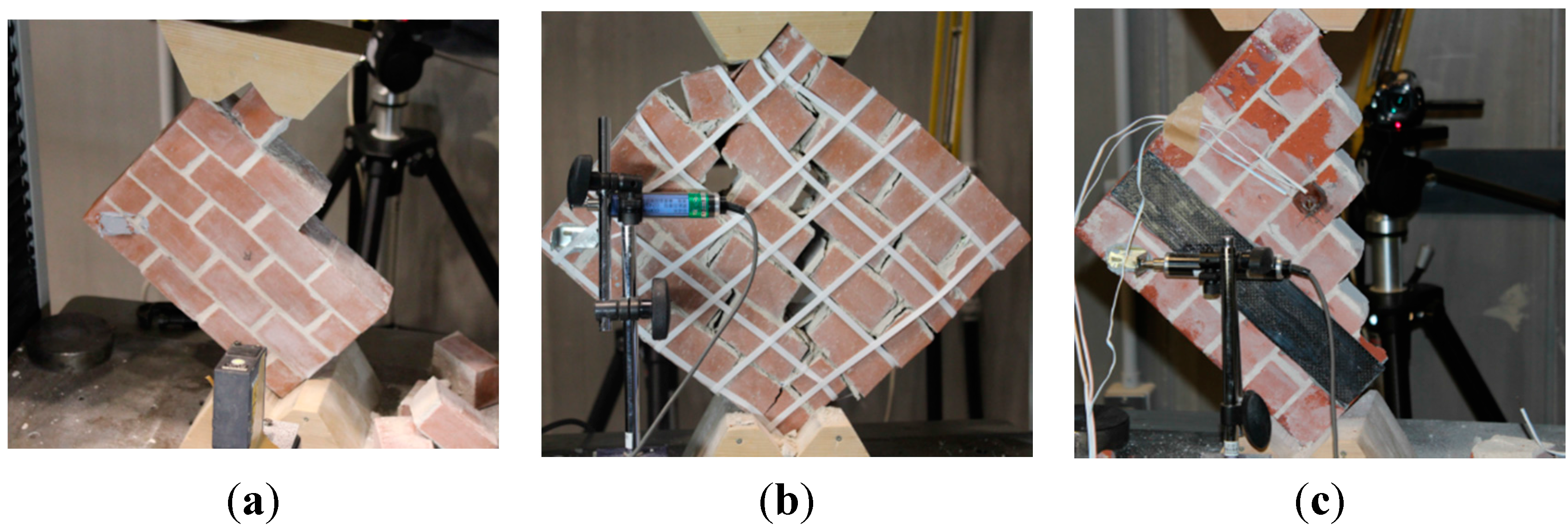
Failure modes and cracking pattern of different types of masonry panels are shown in
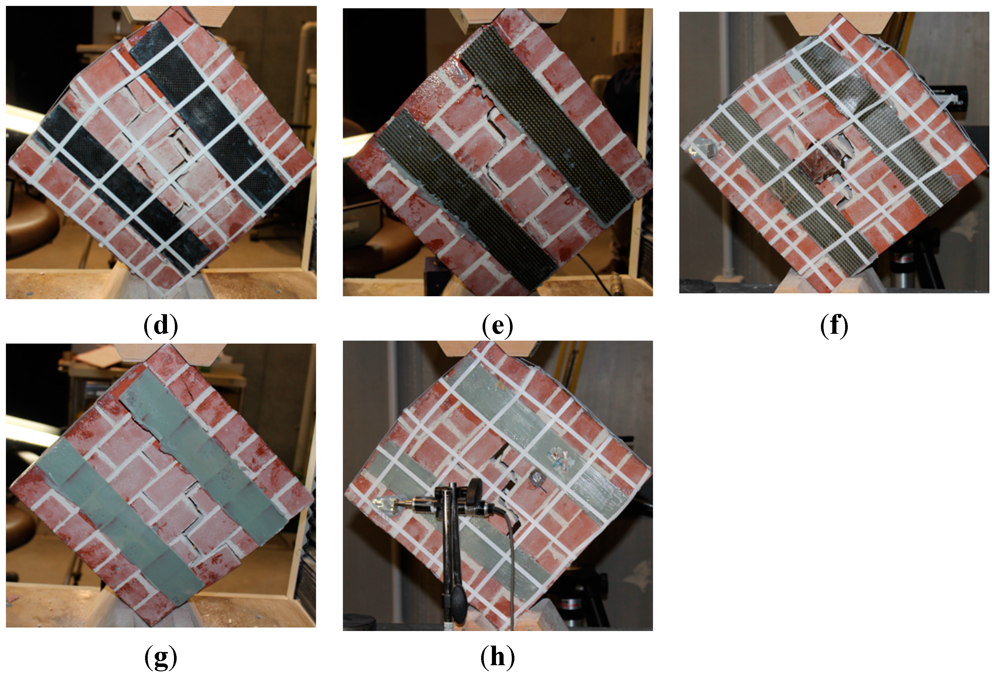
Figure 3.
Figure 3a,b show the cracking pattern of URM and PP-band retrofitted masonry panel. In both of the masonry panels, failure was initiated by a diagonal slip of masonry panel through the mortar joints.
Figure 3c,e,g show the cracking pattern of CFRP, AFRP and GFRP retrofitted masonry panels, respectively. All types of FRP retrofitted panels have exhibited a brittle failure with less ductility and having no warning before failure. In none of the FRP retrofitted panels, fracture of FRP strips was witnessed. In most of the cases, failure was initiated due to detachment of FRP along with a thin layer of brick from the masonry panel surface.
Figure 3c clearly shows the detachment of CFRP with thin layer of brick from masonry panel surface. Similar type of failure was witnesses by Bahman
et al. who performed single lap shear test to evaluate the deboning behavior of FRP from brick surface by using Digital Image Correlation (DIC) technique [
32,
33]. DIC technique is becoming popular among researchers for full-field measurement of strains and deformation by comparing the image features at different mechanical states. Ghorbani
et al. also used DIC technique to predict the cracking pattern and deformation behavior of confined masonry walls [
34].
Figure 3d,f,h show the failure pattern of different FRP + PP-band retrofitted masonry panels.
Figure 3.
Failure mode and cracking pattern of masonry panels under diagonal compression test for (a) URM, (b) PP-band retrofitted, (c) CFRP retrofitted, (d) CFRP + PP-band retrofitted, (e) AFRP retrofitted, (f) AFRP + PP-band retrofitted, (g) GFRP retrofitted, and (h) GFRP + PP-band retrofitted.
Figure 3.
Failure mode and cracking pattern of masonry panels under diagonal compression test for (a) URM, (b) PP-band retrofitted, (c) CFRP retrofitted, (d) CFRP + PP-band retrofitted, (e) AFRP retrofitted, (f) AFRP + PP-band retrofitted, (g) GFRP retrofitted, and (h) GFRP + PP-band retrofitted.
3.2. Out-of-Plane Bending Test Results for Type-1 Masonry Walls
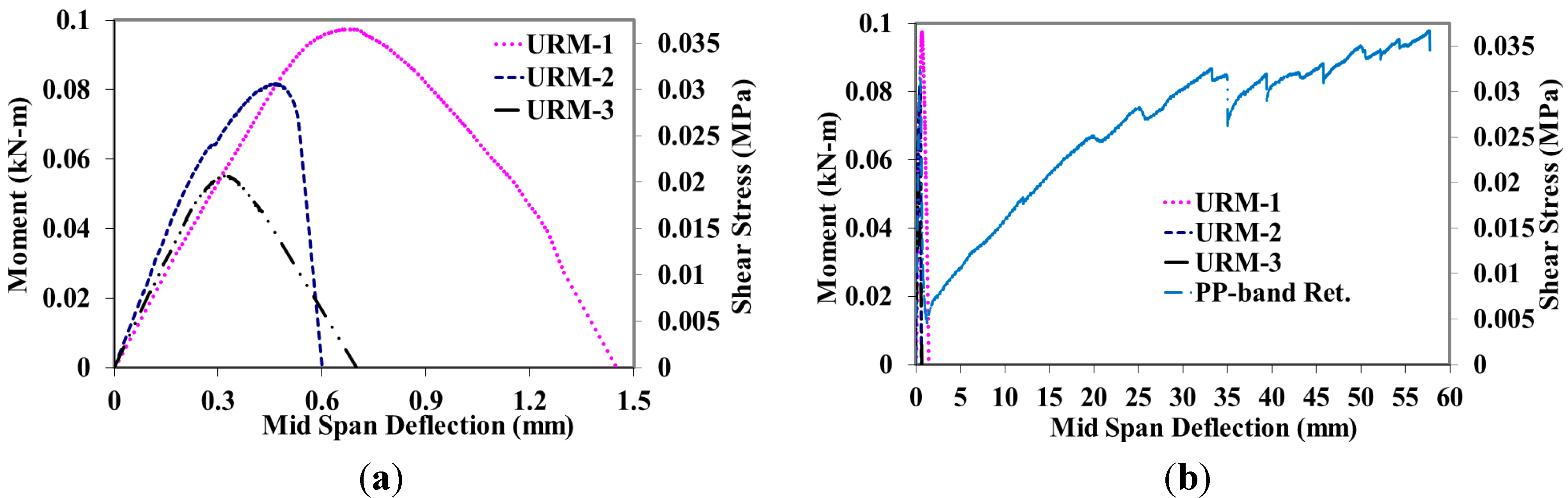
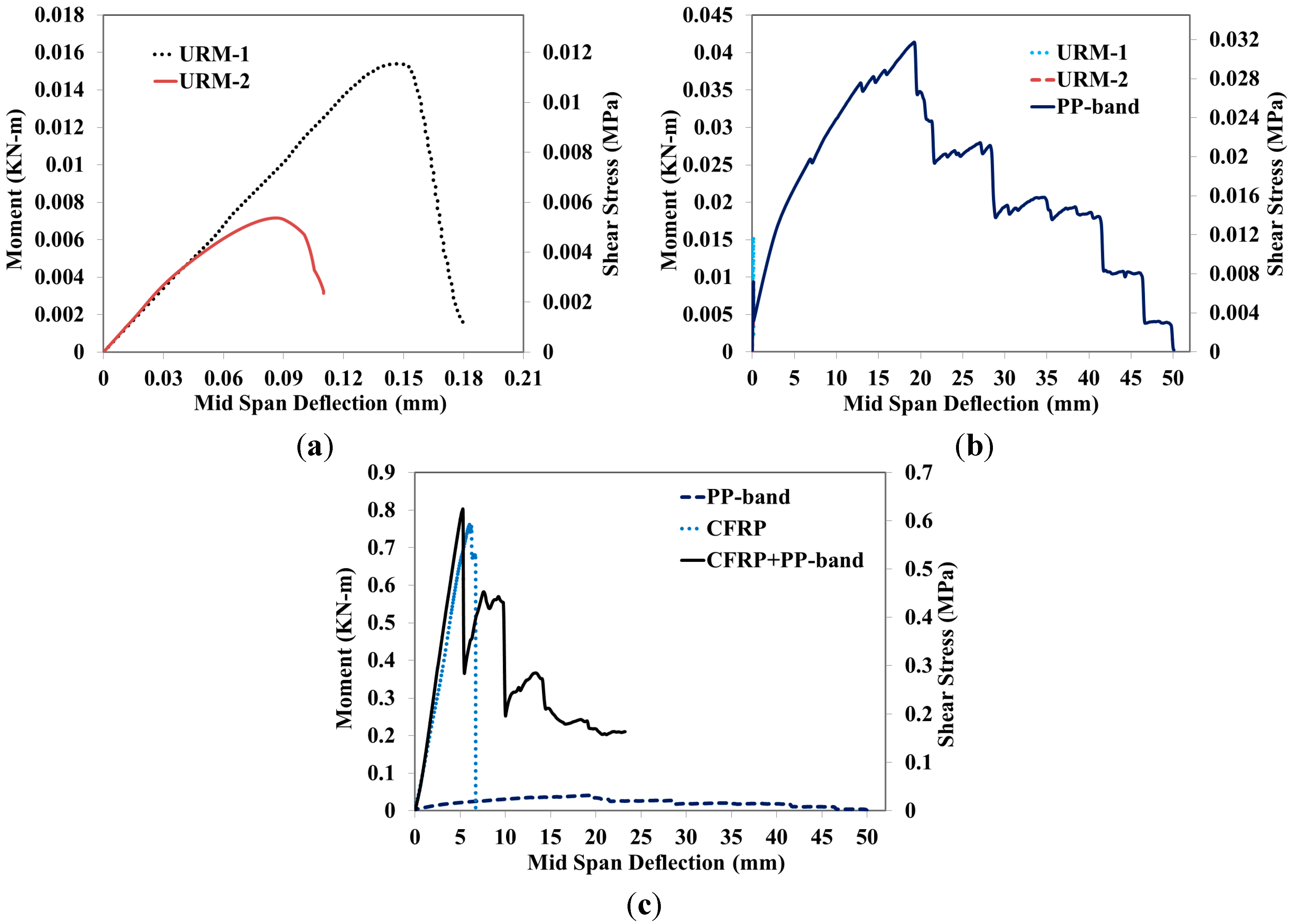
Figure 4a,b show the moment-deflection curves of three URM and PP-band retrofitted masonry panels, whereas corresponding shear stress is plotted on the secondary vertical axis. URM panels have shown a variety of peak strengths with an average value of 0.08 kN-m with almost similar initial stiffness. Behavior of panels was almost linear up to the peak load, as shown in
Figure 4a.
Figure 4b shows the moment-deflection curve of PP-band retrofitted masonry panel. It has shown peak strength of 0.085 kN-m, which is almost the same as that of URM masonry panels. In the case of PP-band retrofitted masonry panel after the deflection of 1.2 mm, it again started taking load and has gone up to a value of 57.7 mm with a moment value of 0.097 kN-m, as shown in
Figure 4b. PP-band retrofitted masonry panel has shown a fairly long deflection and deformation as compared to URM masonry panels.
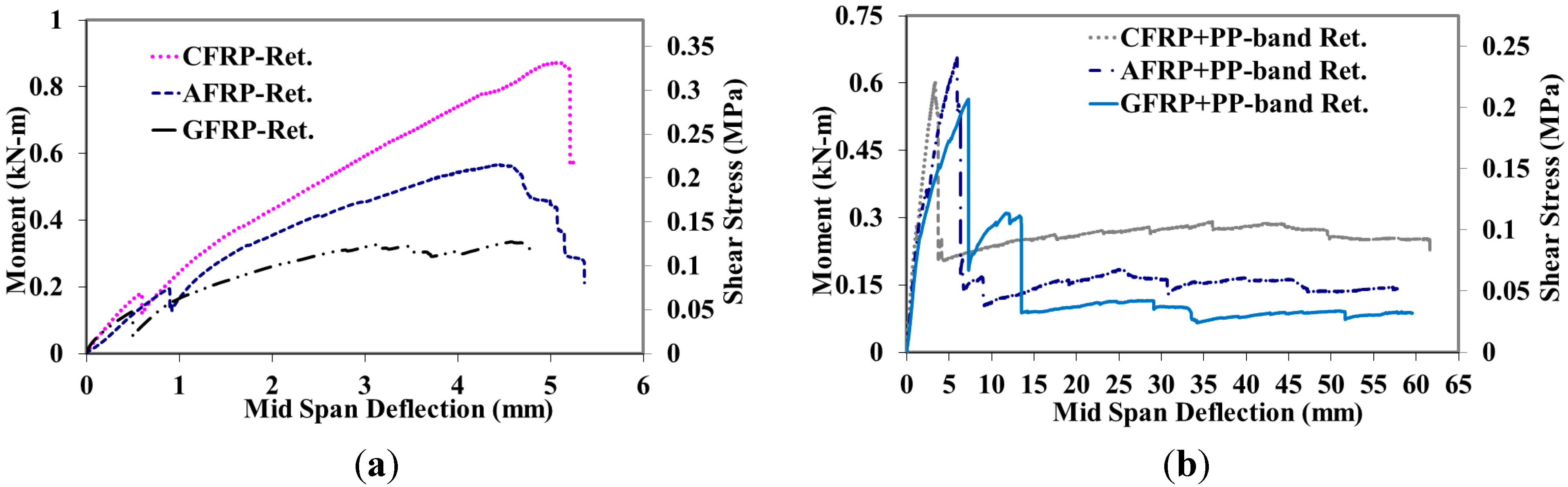
Figure 5a shows the moment-deflection curve of CFRP, AFRP and GFRP retrofitted masonry panels under out-of-plane bending test. Application of FRP has significantly increased the out-of-plane bending strength of masonry panel. CFRP has increased initial peak strength of URM masonry panel from 0.08 to 0.88 kN-m, whereas AFRP and GFRP retrofitted masonry panel has shown a peak strength of 0.59 and 0.33 kN-m, respectively. FRP has increased the failure displacement of URM masonry panels but no residual strength of masonry panels was witnessed. All FRP’s retrofitted masonry panels have shown a brittle failure.
Figure 5a shows an initial drop in strength of FRP retrofitted masonry panels at a displacement range of 0.5 to 0.9 mm. This sudden drop in load was due to separation and falling of a layer of bricks at the inner edge of the masonry panel. After this drop, panels, again, started taking load and reached their corresponding peak strengths.
Figure 4.
Moment-deflection curves of masonry panels under bending test for (a) URM and (b) PP-band retrofitted.
Figure 4.
Moment-deflection curves of masonry panels under bending test for (a) URM and (b) PP-band retrofitted.
Figure 5.
Moment-deflection curves under out-of-plane bending test for (a) CFRP, AFRP and GFRP retrofitted masonry panels and (b) CFRP + PP-band, AFRP + PP-band and GFRP + PP-band retrofitted masonry panels.
Figure 5.
Moment-deflection curves under out-of-plane bending test for (a) CFRP, AFRP and GFRP retrofitted masonry panels and (b) CFRP + PP-band, AFRP + PP-band and GFRP + PP-band retrofitted masonry panels.
Figure 5b shows moment-deflection curves for CFRP + PP-band, AFRP + PP-band and GFRP + PP-band retrofitted masonry panels. Application of FRP has increased the initial strength of URM masonry panel compared to that of only FRP retrofitted masonry panels. This increase in strength was variable depending upon the type of FRP used and its application on the surface of masonry panel. Presence of PP-band has increased the displacement carrying capacity of masonry panel as that of only PP-band retrofitted masonry panel. In addition to these two predictive effects, FRP + PP-band retrofitted masonry panels have shown a higher residual strength compared to only PP-band retrofitted masonry panel. In the case of CFRP + PP-band and GFRP + PP-band retrofitted masonry panels, this residual strength was even greater than the strength of URM masonry panel.
Figure 5b also shows that, the initial drop of strength due to detachment of brick layers as seen in
Figure 5a was either vanished or moved to higher load levels due to the presence of PP-band on the surface of masonry panels. All FRP + PP-band retrofitted masonry panels have increased the initial strength, residual strength and deformation capacity of masonry panels.
Failure Modes for Type-1 Walls
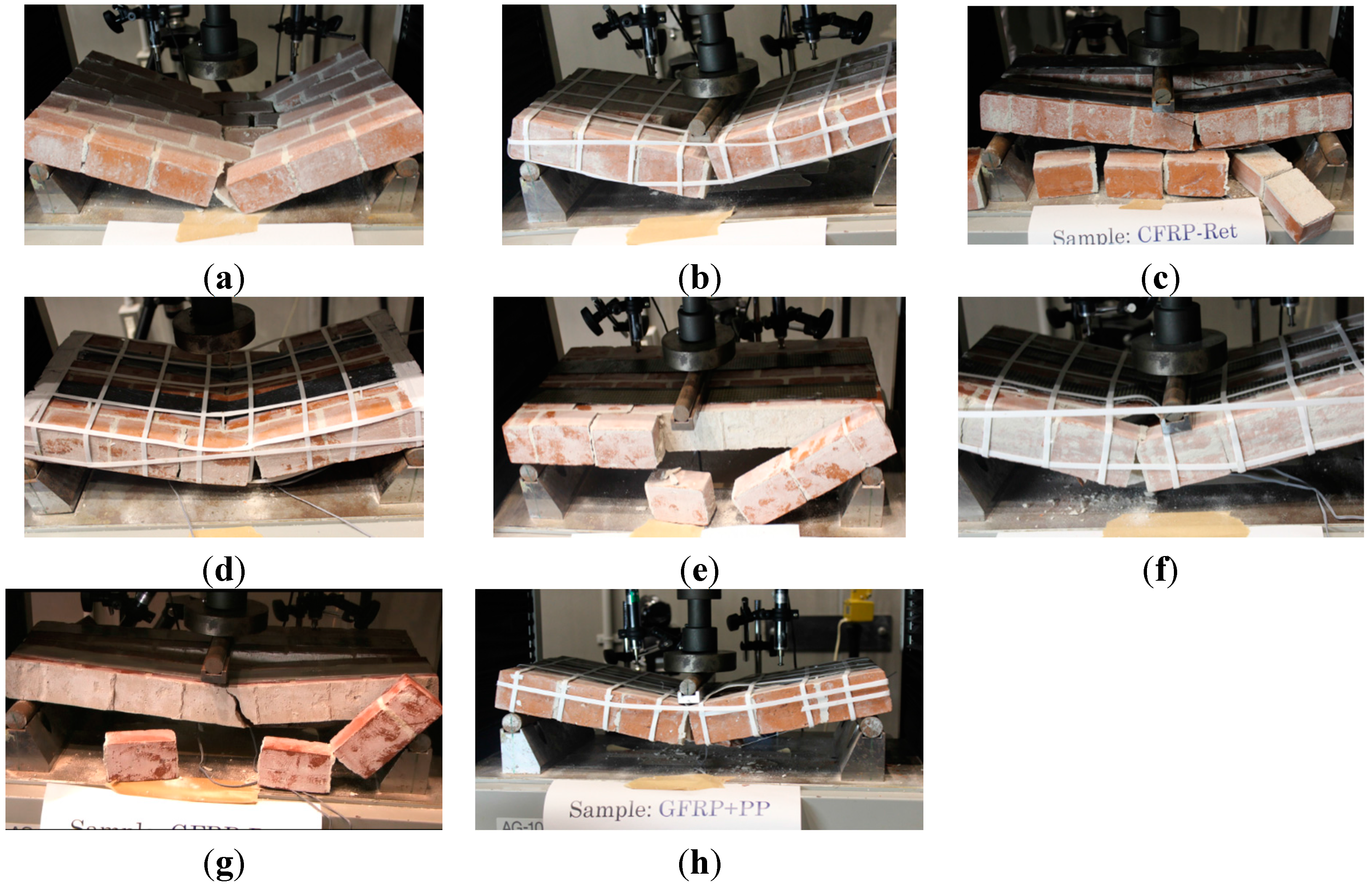
Figure 6 shows that failure pattern of different type of masonry panels under out-of-plane bending test.
Figure 6a shows a pure bending type of failure with major bending cracks and spalling of bricks from the central part of the panels. There were no signs of shear failure near supports.
Figure 6b shows that PP-band retrofitted masonry panel failure. Failure of PP-band retrofitted masonry panels was the same as that of URM masonry panels but the presence of PP-band kept the brick masonry as a single unit. PP-band has not provided any increase in bending strength but after the initial drop of strength due to masonry failure, PP-band enabled the panel to take load after the initial failure.
Figure 6c,e,g show the failure of CFRP, AFRP and GFRP retrofitted masonry panels. All FRP retrofitted masonry panels have shown a stepwise failure initiated with the fall of inner and outer bricklayers. Brittle failure of panels was mainly due to detachment and debonding of FRP from brick surface. No FRP rupture was witnessed in any of CFRP, AFRP and GFRP retrofitted masonry panel, failure was due to delamination of FRP from the panel surface. Failure patterns of CFRP + PP-band, AFRP + PP-band and GFRP + PP-band retrofitted masonry panels are shown in
Figure 6d,f,h, respectively. Initial failure of all three FRP + PP-band retrofitted masonry panels was similar as that of only FRP retrofitted masonry panels but presence of PP-band did not allow the masonry panel to dismember and kept it as one unit which enabled it to undergo further displacements.
Figure 6.
Failure mode and cracking pattern of Type-1 masonry panels under out-of-plane bending test for (a) URM, (b) PP-band retrofitted, (c) CFRP retrofitted, (d) CFRP + PP-band retrofitted, (e) AFRP retrofitted, (f) AFRP + PP-band retrofitted, (g) GFRP retrofitted, and (h) GFRP + PP-band retrofitted.
3.3. Out-of-Plane Bending Test Results for Type-2 Masonry Walls
Figure 7 shows the moment-deflection curves of URM, PP-band retrofitted, CFRP and CFRP + PP-band retrofitted masonry panels under out-of-plane bending test for Type-2 walls, whereas their corresponding shear stress values are plotted on secondary vertical axis.
Figure 7a shows the moment-deflection curves of URM masonry panels. Both of URM masonry panels have shown a variety of peak strengths ranging from 0.0066 to 0.0154 kN-m, which is significantly less than peak strength of URM panels in Type-1 as shown in
Figure 4a.
Figure 7b shows the moment-deflection curve for PP-band retrofitted masonry panel along with URM masonry panels. PP-band has shown almost same peak strength as that of URM masonry panels but it has shown a long deformation capacity.
Figure 7c shows that CFRP has increased the URM strength from 0.0154 to 0.77 kN-m, but failure displacement was far less than PP-band retrofitted masonry panel. CFRP + PP-band retrofitted masonry panel has increased the peak strength from 0.0154 to 0.79 kN-m and failure displacement from 0.17 to almost 44 mm as shown in
Figure 7c. Type-2 masonry panels have shown similar type of behavior as that of their corresponding Type-1 masonry panels but in Type-2 masonry panels, the residual strength has vanished by stepwise degradation, as shown in
Figure 7b,c. This phenomenon could be due to gradual separation of bricks from mortar as all bed joints are parallel to the plane of loading.
Figure 7.
Moment-deflection curves of Type-2 masonry panels under out-of-plane load for (a) URM, (b) URM and PP-band retrofitted and (c) PP-band, CFRP and CFRP + PP-band retrofitted.
Figure 7.
Moment-deflection curves of Type-2 masonry panels under out-of-plane load for (a) URM, (b) URM and PP-band retrofitted and (c) PP-band, CFRP and CFRP + PP-band retrofitted.
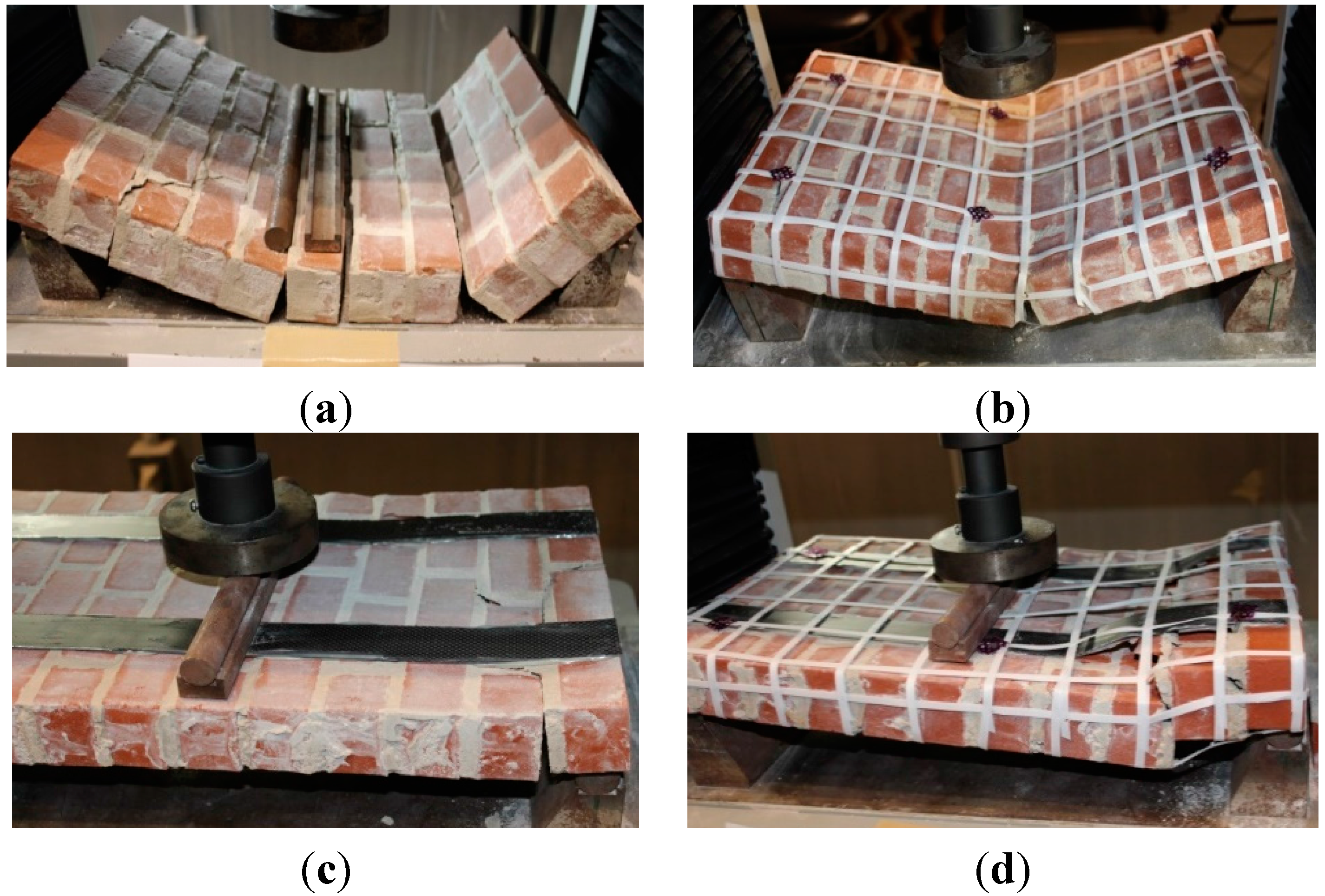
Failure Modes for Type-2 Walls
Figure 8a–d shows the failure pattern of masonry panel under out-of-plane loading for Type-2 walls. Failure patterns were also similar as that of Type-1 masonry panels. URM has shown a highly brittle failure with separation of wall segments at bed joints as shown in
Figure 8a. In the case of PP-band retrofitted masonry panel, failure was gradual and panel did not break into different segments as shown in
Figure 8b.
Figure 8c shows failure of CFRP retrofitted masonry panel. CFRP retrofitted masonry panels failed by delamination of CFRP from the bottom face at a section located near the supports, which shows a kind of shear failure near the support. Once the delamination of CFRP started, it did not stop and, finally, the panel broke into several pieces.
Figure 8d shows the failure of CFRP + PP-band retrofitted masonry panel. Failure started by the delamination of CFRP from the panel surface near the support, but PP-band hindered the complete delamination and breaking of panel into small pieces, as shown in
Figure 8d.
Figure 8.
Failure mode and cracking pattern of Type-2 masonry panels under out-of-plane bending test for (a) URM, (b) PP-band retrofitted, (c) CFRP retrofitted, and (d) CFRP + PP-band retrofitted.
Figure 8.
Failure mode and cracking pattern of Type-2 masonry panels under out-of-plane bending test for (a) URM, (b) PP-band retrofitted, (c) CFRP retrofitted, and (d) CFRP + PP-band retrofitted.
4. Retrofitting Procedure
For in-plane diagonal compression test, all FRP and FRP + PP-band retrofitted masonry panel were retrofitted by 50 mm × 0.5 mm FRP strips. Whereas for out-of-plane bending test, FRP strip width of 40 mm with fabric thickness of 0.5 mm was used. In the case of FRP and FRP + PP-band retrofitted masonry panels, quantity of FRP was decided based upon the FRP reinforcement ratios used in experiments conducted in the past [
12,
16,
18,
35,
36,
37,
38]. The surfaces of masonry walls were cleaned with the help of a wet cloth and then FRP was applied on both faces of wall using strong epoxy glue.
In the case of PP-band and FRP + PP-band retrofitted masonry panels, PP-band mesh pitch of 50 mm was used. Mesh pitch was decided based upon the parametric study carried out by Sathiparan (2005) and Mayorca and Meguro (2008) [
26,
39]. PP-band mesh making process is very simple and do not require any skilled labor. Unbonded and untensioned PP-bands are arranged in a mesh fashion and connected at their intersection points using portable ultrasonic welder. Mesh of PP-bands with any desired pitch is prepared commercially by using ultrasonic welding machine in which multiple ultrasonic welders are arranged in rows. Holes are drilled through the wall at approximately four times the mesh pitch for an existing masonry wall and small straws/pipes are left embedded at the joints in the case of new construction [
39].
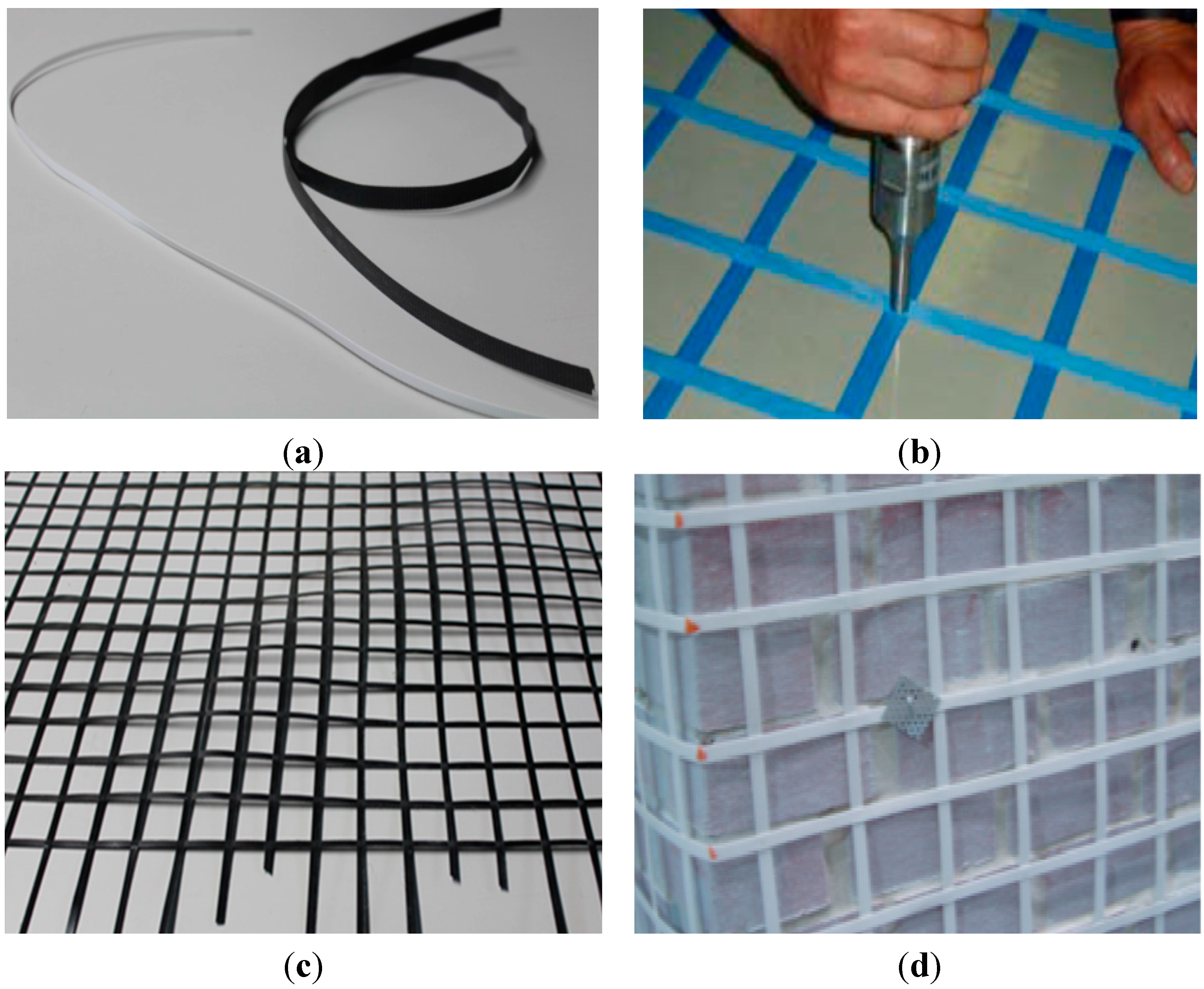
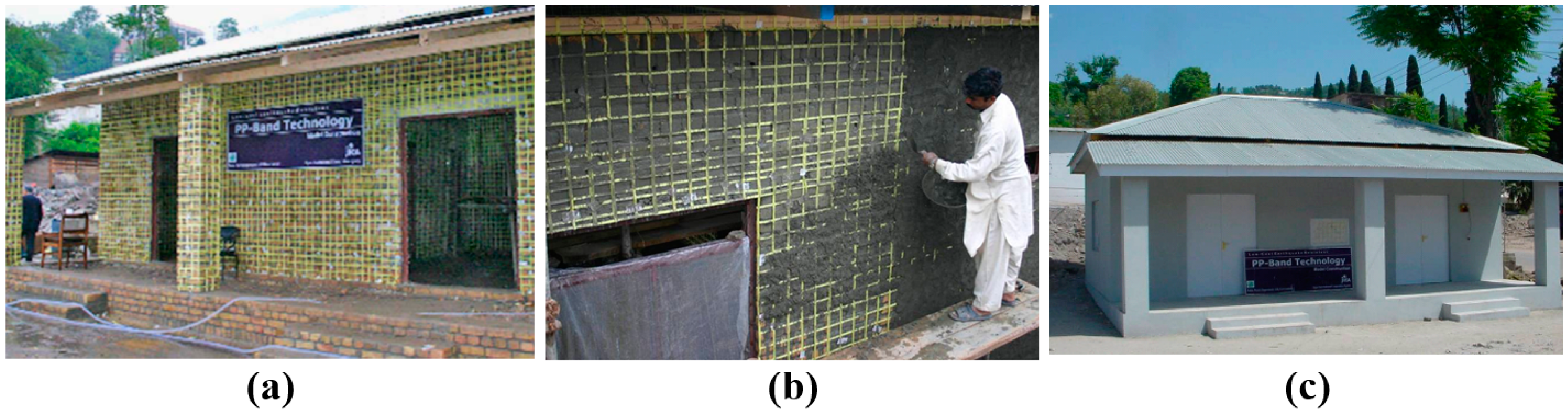
Figure 9 shows some of the features of PP-band retrofitting method.
Figure 9a,b show Polypropylene bands and mesh making process, whereas
Figure 9c shows PP-band meshes prepared by ultrasonic welding machine. Once PP-band mesh is ready, it can be applied on both faces of wall with the help of out-of-plane connectors, as shown in
Figure 9d. These out-of-plane connectors could be a steel wire, PP string or PP-band itself. PP-band is attached on walls with the help of out-of-plane connectors and no epoxy is applied on wall surface. At wall edges or corners PP-bands are connected with the help of portable ultrasonic welders, which are commercially available in markets and could be easily brought to the site. After applying the PP-band mesh on masonry walls, a layer of surface finish is applied, which gives an appearance just like an ordinary masonry house as shown in
Figure 10 [
28].
Figure 9.
Retrofitting of masonry walls using PP-band mesh: (a) Unbonded and untensioned PP-band, (b) ultrasonic welding of PP-bands, (c) PP-band mesh prepared by ultrasonic welding machine, and (d) out-of-plane connection of PP-band mesh.
Figure 9.
Retrofitting of masonry walls using PP-band mesh: (a) Unbonded and untensioned PP-band, (b) ultrasonic welding of PP-bands, (c) PP-band mesh prepared by ultrasonic welding machine, and (d) out-of-plane connection of PP-band mesh.
Figure 10.
Application of PP-band retrofitting technology in Pakistan, (
a) PP-band retrofitted house, (
b) plastering of PP-band retrofitted house, and (
c) surface Finished PP-band retrofitted house [
28].
Figure 10.
Application of PP-band retrofitting technology in Pakistan, (
a) PP-band retrofitted house, (
b) plastering of PP-band retrofitted house, and (
c) surface Finished PP-band retrofitted house [
28].
5. Experimental Program
Current experimental study is carried out to evaluate the alternate strengthening techniques for URM masonry structures. Many researchers have tried to evaluate the performance of retrofitted masonry using full-scale brick units with size of masonry panels ranging from 1070 to 1975 mm but it requires large size testing facilities and a large amount of research funds [
10,
18,
19,
38]. Structural tests of scaled models are also an alternative to understand the behavior of masonry wall system. Many researchers have carried out experiments using scaled bricks and scaled size of masonry panels (ranging from 300 to 600 mm) based upon available testing facilities and number of units to be tested [
12,
16,
40,
41].
In most of developing countries, length of brick ranges from 200 to 300 mm, whereas thickness of mortar ranges from 13 to 20 mm. Keeping in mind aforementioned aspects, length of the brick was scaled down to 75 mm for better handling, laying and based upon available manufacturing facilities, whereas depth of brick was kept half of its length. Thickness of brick was kept 50 mm to provide sufficient out-of-plane stability during application of in-plane loads. Thickness of mortar was kept 5 mm to control the consistency of the wall panels and to allow the failure, either inside the mortar or at brick mortar interface.
5.1. Test Specimens and Setup
5.1.1. Diagonal Compression Test
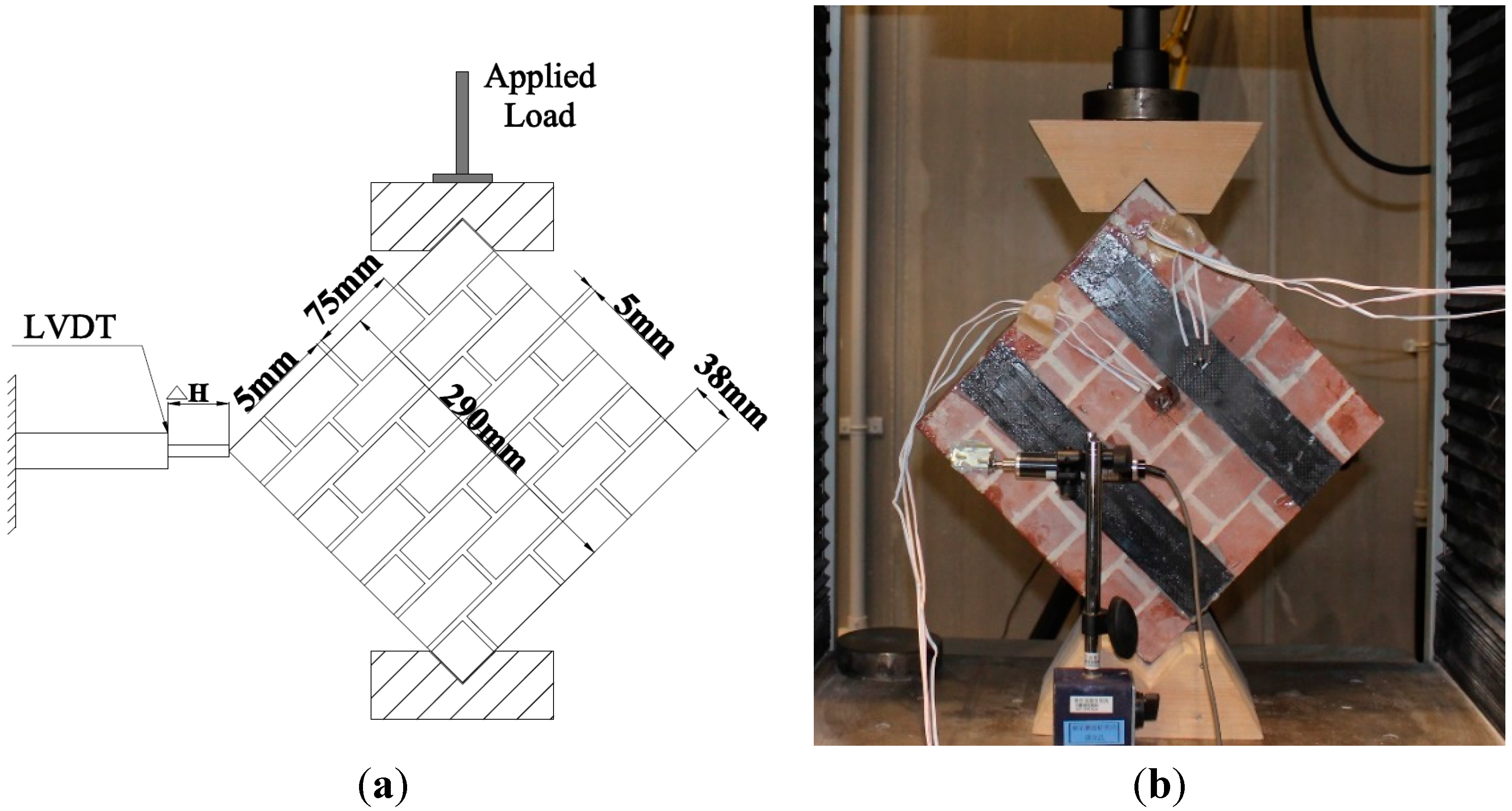
Figure 11 shows test setup of masonry panels under diagonal compression test. Same test setup was used for all masonry panels. All panels were tested with the same initial rate of loading up to the first initial peak load; after that, different loading rates were used depending upon the type of masonry panel. In the case of the URM masonry panel, and all FRP retrofitted masonry panels, a loading rate of 0.15 mm/min was used up to the failure of masonry panels. For PP-band retrofitted and FRP + PP-band retrofitted masonry panels, loading rate of 0.15 mm/min was used up to initial peak, but after the initial failure peak, loading rate was increased to 1.00 mm/min to evaluate the performance of PP-band and FRP + PP-band retrofitted panels under higher diagonal displacements. Diagonal force over the corners of masonry panels was applied with specially designed strong wooden wedges placed at top and bottom platens of 100 kN Universal Testing Machine (UTM) manufactured by Shimadzu Scientific Instruments (SSI), Kyoto, Japan, as shown in
Figure 11a,b. In-plane displacements of masonry panels were measured with linear variable displacement transducers (LVDT) of 500 × 10
−6 mm sensitivity.
Figure 11.
Test setup for diagonal compression test: (a) schematic and (b) experimental.
Figure 11.
Test setup for diagonal compression test: (a) schematic and (b) experimental.
Recorded horizontal and vertical deformation and diagonal loads are converted to corresponding stress and strains by the following Equations (1) and (2):
where
P = load applied, α = angle between the load and wallet top surface,
L = length of wallet,
W = height of wall,
t = thickness of wall, ∆
V = vertical deformation and ∆
H = horizontal deformation.
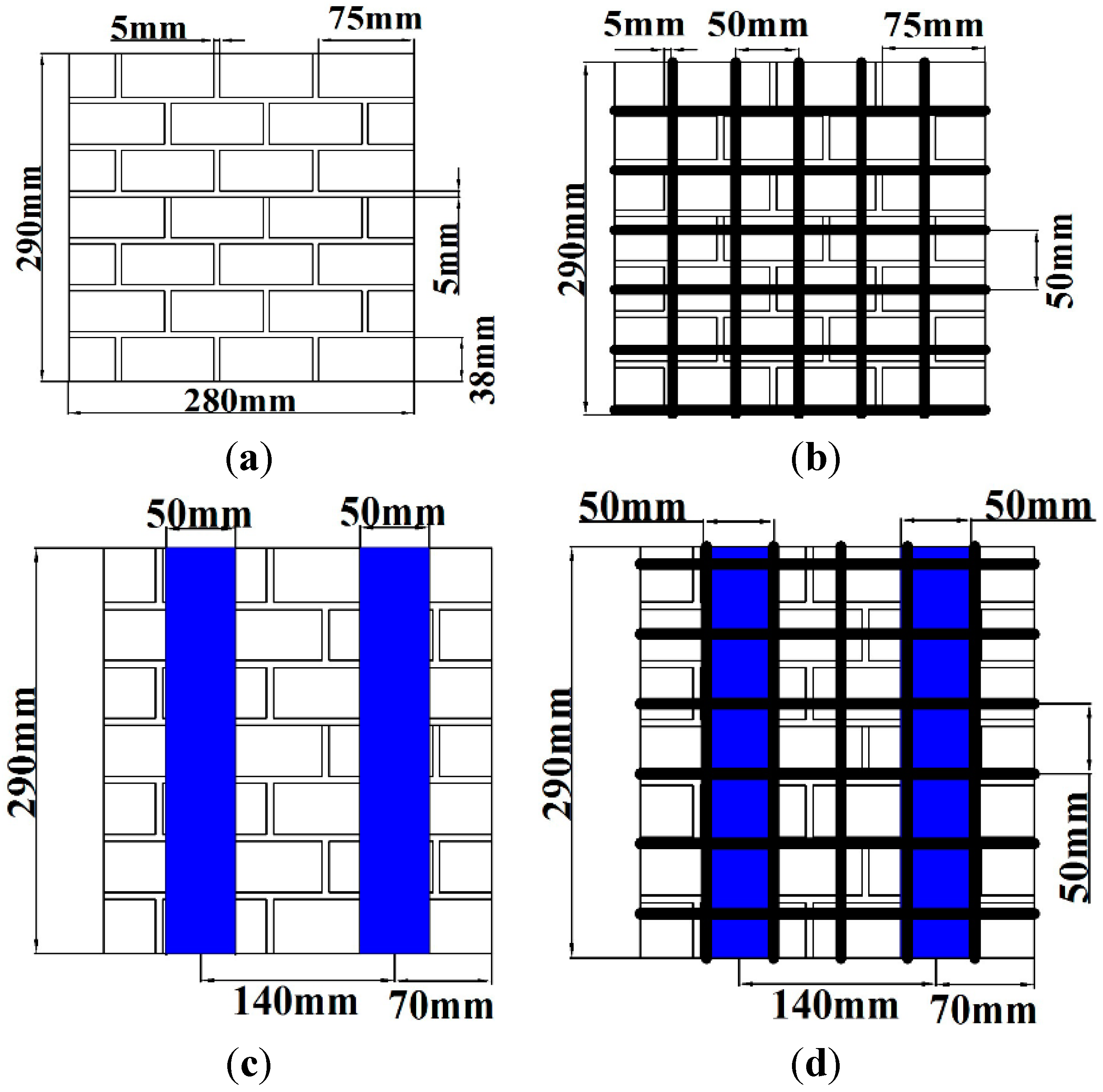
Panel retrofitting scheme for in-plane diagonal compression test is shown in
Figure 12. In the case of three FRP retrofitted panels, each one of the panels was retrofitted with CFRP, AFRP and GFRP. Similarly, out of three FRP + PP-band retrofitted masonry panels, the first panel was CFRP + PP-band retrofitted, the second was AFRP + PP-band retrofitted, and the third was GFRP + PP-band retrofitted masonry panel. Dimensions of each masonry panel were 280 mm × 290 mm × 50 mm, made with 75 mm × 38 mm × 50 mm brick units, as shown in
Figure 12. Mortar mixed proportion of cement, lime and sand (140 g:1110 g:2800 g) with 0.14 water/cement ratio was used for in-plane diagonal compression test. Five-millimeter mortar thickness was used for both vertical and horizontal joints.
Figure 12.
Panel retrofitting scheme for in-plane diagonal compression test: (a) non-retrofitted masonry panel, (b) PP-band retrofitted masonry panels, (c) FRP retrofitted masonry panel, and (d) FRP + PP-band retrofitted masonry panel.
Figure 12.
Panel retrofitting scheme for in-plane diagonal compression test: (a) non-retrofitted masonry panel, (b) PP-band retrofitted masonry panels, (c) FRP retrofitted masonry panel, and (d) FRP + PP-band retrofitted masonry panel.
5.1.2. Out-of-Plane Load Test
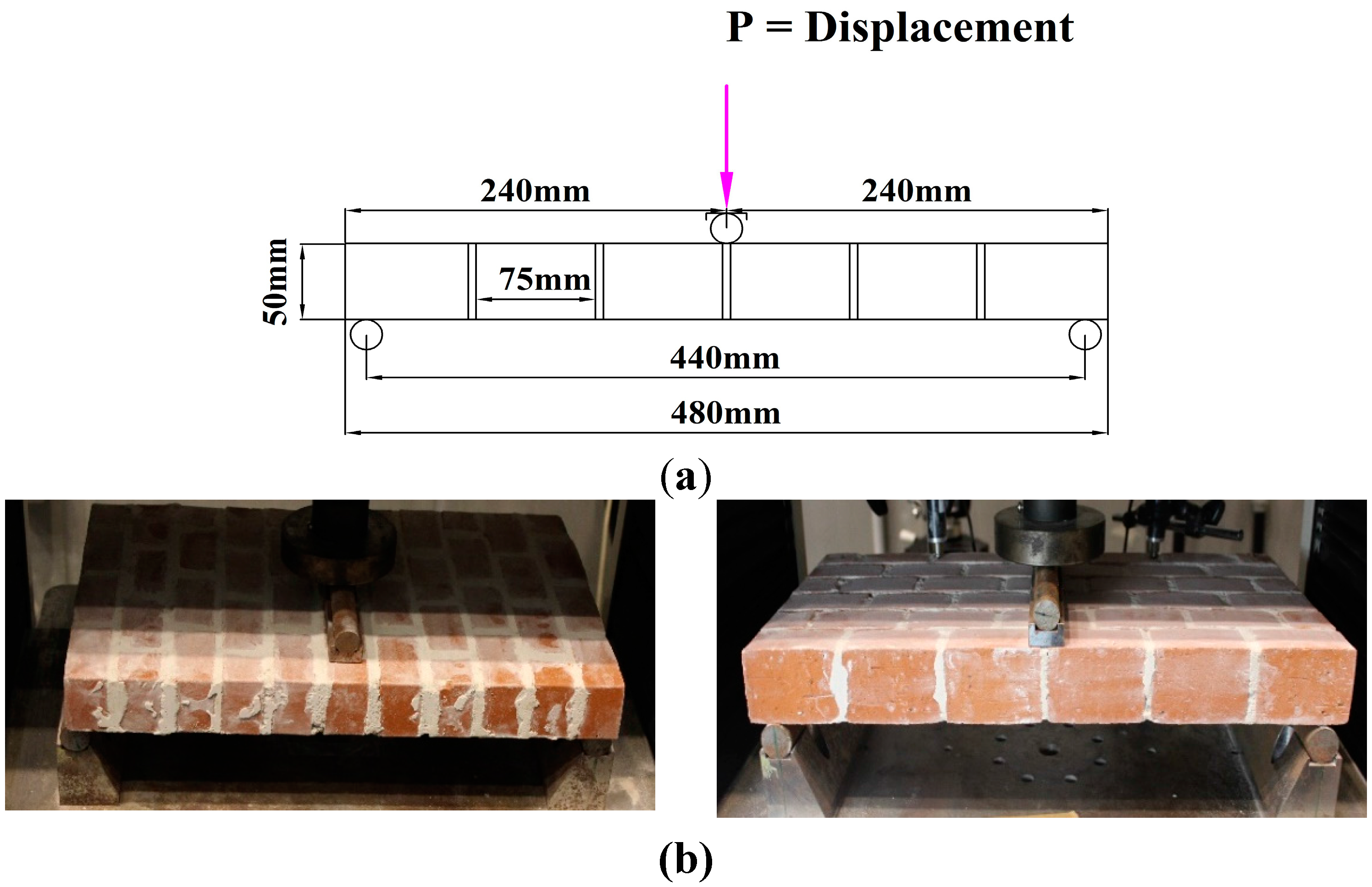
In out-of-plane bending test, masonry panels were tested like a simply support beam having center-to-center span of 440 mm with a line load applied at the center of span throughout the width of the masonry panel, as shown in
Figure 13a,b. Different displacement loading rates were selected depending upon the failure displacement and duration of test. All masonry panels were tested at initial loading rate of 0.1 mm/min up to the initial peak, whereas PP-band and FRP + PP-band retrofitted panels had 2 mm/min loading rate after the initial failure. Two LDTV displacement transducers with 500 × 10
−6 mm sensitivity were attached at quarter span to measure deflections. Wall specimens were simply supported on two specially designed steel rollers and applied displacement was transferred from machine to specimen with the help of steel roller and a cap plate as shown in
Figure 13b. A small initial displacement is applied to assure the full contact of the panel and loading arrangement.
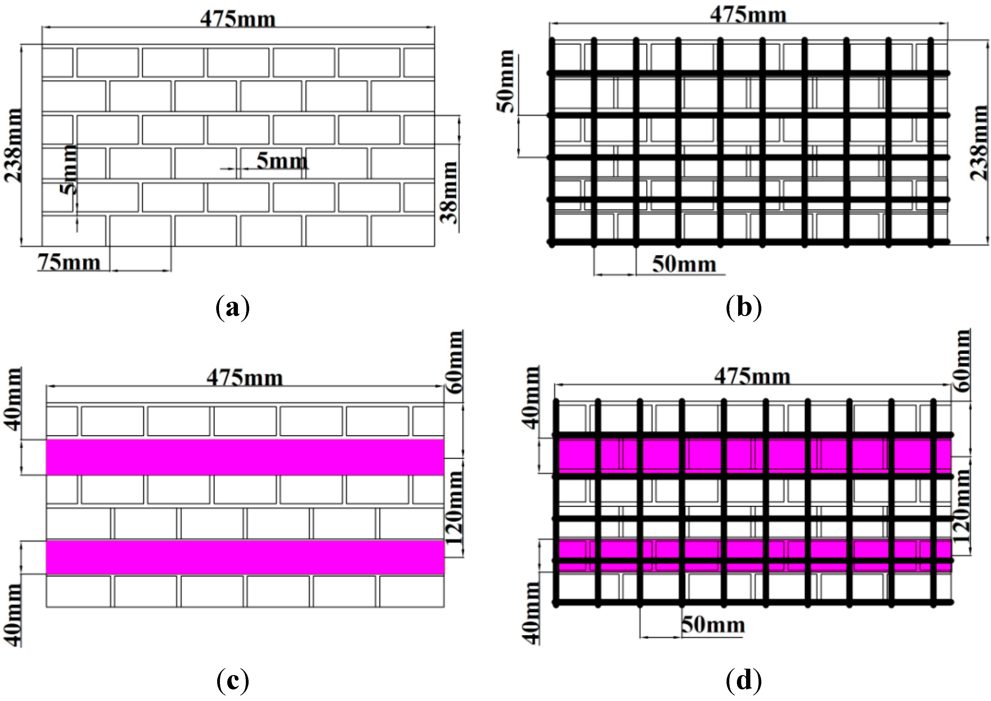
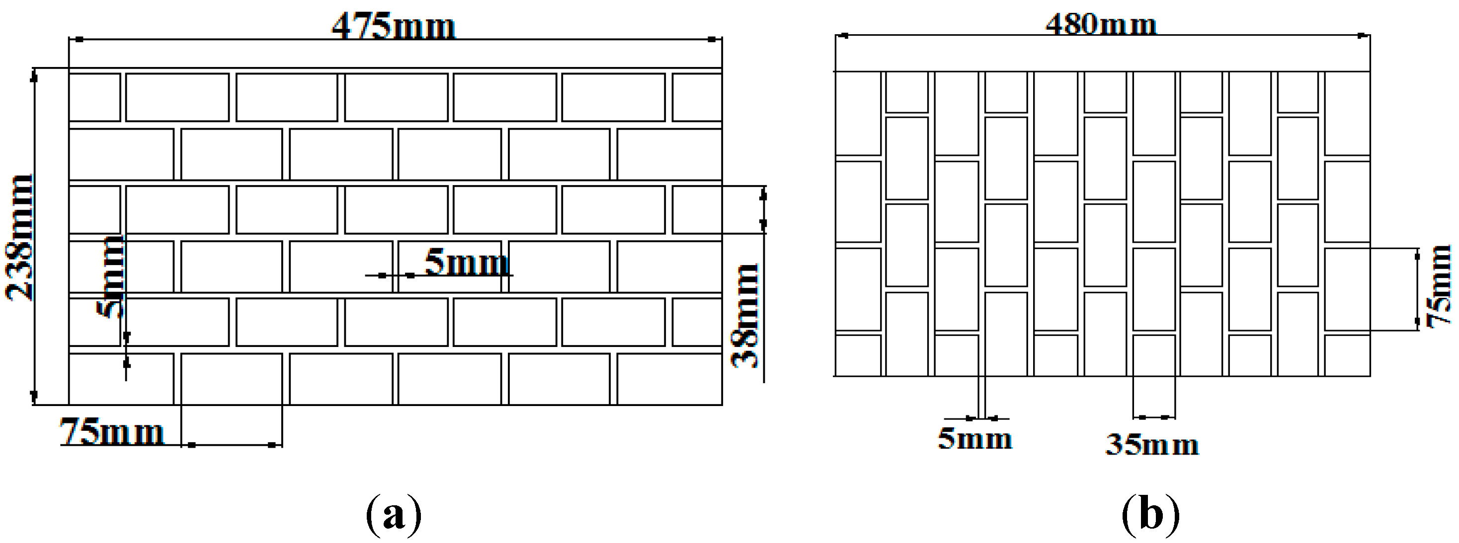
Masonry walls under lateral loads can have either only uniaxial bending or biaxial bending depending upon the aspect ratio (length/height) of wall and its boundary conditions (presence of other walls perpendicular to wall under consideration). In order to consider this effect, two types of masonry panels were constructed. Type-1 corresponds to a condition where wall is long and tall (length/height > 0.5) having bending about longitudinal and vertical axis of the wall, whereas Type-2 represents a condition when walls are tall (aspect ratio < 0.5) having bending only about the longitudinal axis of the wall. For Type-2 walls, it was very difficult to test walls under biaxial bending, so in order to simplify the testing plan, two types of walls were constructed for each case, as shown in
Figure 14. In Type-1 masonry panels, bed joints of wall were kept parallel to horizontal axis, whereas in Type-2 bed joint were kept perpendicular to horizontal axis.
Figure 13.
Test setups of masonry panels under out-of-plane bending test: (a) schematic and (b) experimental.
Figure 13.
Test setups of masonry panels under out-of-plane bending test: (a) schematic and (b) experimental.
Figure 14.
Layout of Type-1 and Type-2 masonry panels for out-of-plane bending test: (a) Type-1 and (b) Type-2.
Figure 14.
Layout of Type-1 and Type-2 masonry panels for out-of-plane bending test: (a) Type-1 and (b) Type-2.
Figure 15 shows the testing plan for out-of-plane load tests for Type-1 and Type-2 walls. Ten masonry panels were tested in out-of-plane direction for Type-1 walls. Out of ten masonry panels, three were non-retrofitted, named URM-1, URM-2 and URM-3; one was PP-band retrofitted; three were CFRP, AFRP and GFRP retrofitted; and three were CFRP + PP, AFRP + PP and GFRP + PP-band retrofitted masonry panels. Size of each masonry panel was 475 mm × 238 mm × 50 mm. Five wall panels were constructed for Type-2 walls, out of five masonry panels, two were non-retrofitted, one was PP-band retrofitted, one was CFRP retrofitted, and one was CFRP + PP-band retrofitted. All masonry wall panels were constructed, cured and tested under similar conditions.
Figure 15.
Panels retrofitting scheme for out-of-plane bending test: (a) non-retrofitted masonry panel, (b) PP-band retrofitted masonry panels, (c) FRP retrofitted masonry panel, and (d) FRP + PP-band retrofitted masonry panel.
Figure 15.
Panels retrofitting scheme for out-of-plane bending test: (a) non-retrofitted masonry panel, (b) PP-band retrofitted masonry panels, (c) FRP retrofitted masonry panel, and (d) FRP + PP-band retrofitted masonry panel.
5.2. Material Properties
5.2.1. FRP, Polypropylene Band (PP-band) and Epoxy
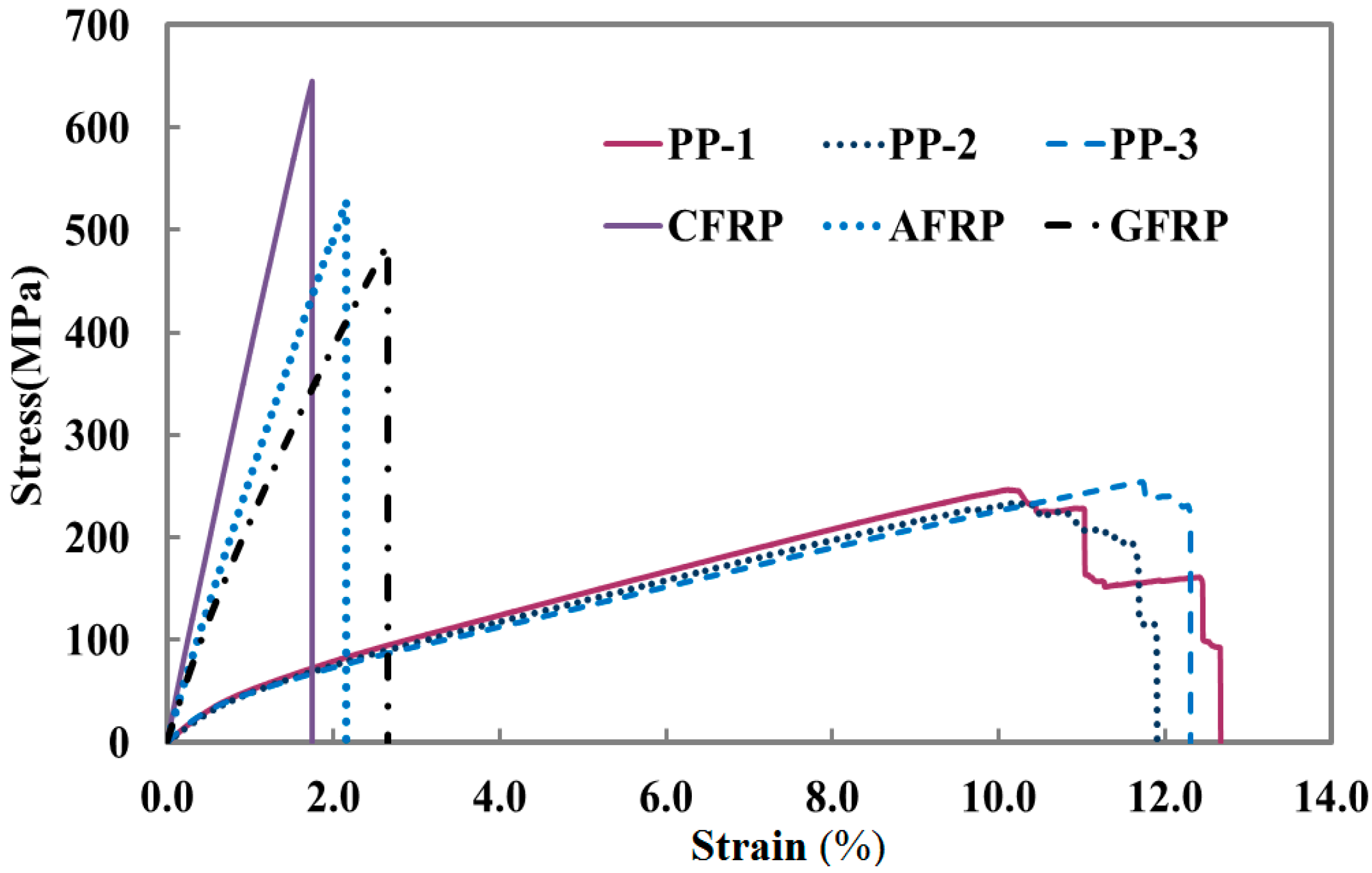
Figure 16 shows the stress-strain curve of three PP-bands samples (PP-1, PP-2 and PP-3) of same polypropylene material and three different types of FRPs (CFRP, AFRP and GFRP) supplied by Sekisui Jushi Strapping Co. Milton Keynes, UK and Sankyo Manufacturers, Yokohama, Japan, respectively. PP-bands and FRPs were tested under uniaxial tensile conditions.
Figure 16 shows that all three PP-band samples have shown a bi-linear behavior having initial and residual modulus of elasticity of 6.92 and 1.98 GPa. Three different types of FRP materials were used in order to find the best economical and efficient type of FRP to be used with the PP-band. For this purpose, CFRP, AFRP and GFRP were used. Out of these three, CFRP was found to be the most expensive and GFRP was the cheapest among all. All FRPs carry a biaxial type of fiber layout having fabric thickness of 0.5 mm. CFRP, AFRP and GFRP have shown a linear elastic behavior with tensile modulus of elasticity of 37, 24 and 18 GPa, respectively.
Figure 16 shows that FRP has high stiffness and tensile strength with poor elongation capacity, whereas PP-bands have comparatively low strength, but have higher strain values compared to CFRP, AFRP and GFRP. Failure behavior and strength increment are mainly function of FRP strength, epoxy used and the surface on which it is applied. Two types of epoxies are available, the first adhesive is epoxy resin and other is a flexible polyurethane polymer. Flexible polyurethane polymer with higher ductility and lower tensile modulus can ensure lesser brittle failure of FRP systems but strength increment could not be sufficient due to movability of applied composites. According to Bhaman
et al., due to higher tensile modulus, epoxy resin can contribute much higher in terms of strength as compared to flexible polymer resins [
32]. In this study, an epoxy resin Epoxy Bond E-250 was used as it has strong bonding properties with lower debonding strain values.
Table 1 summarizes the properties of epoxy resin (Epoxy Bond E-250) used to apply FRP over the masonry wall surface. All epoxy strength parameters were provided by the epoxy supplier Konishi Chemical Ind., Wakayama, Japan and examined at a temperature of 20 ± 1 °C after curing time of seven days.
Figure 16.
Stress-strain curves of CFRP, AFRP, GFRP and PP-band.
Figure 16.
Stress-strain curves of CFRP, AFRP, GFRP and PP-band.
Table 1.
Material properties of epoxy.
Table 1.
Material properties of epoxy.
| Material Property | Value | Units |
|---|
| Tensile Strength | 20 | MPa |
| Tensile shear strength | 9.6 | MPa |
| Compressive shear bond strength | 21 | MPa |
| Modulus of elasticity | 1.5 | GPa |
5.2.2. Properties of Masonry
Material properties of brick, mortar, and masonry were determined by performing compression, shear and bond tests on bricks, mortar and masonry prisms. Material testing results are summarized in
Table 2. Compression test on clay burnt bricks was carried out according to ASTM C67-03a [
42]. Average compressive strength of brick samples was determined by performing compression test on three brick samples of 75 mm × 38 mm × 50 mm. Brick work for masonry walls was conducted using a cement lime mortar. Two different types of mortar were used for diagonal compression test and three point bending test. Weight mixed proportion of cement, lime and sand (140 g:1110 g:2800 g) with 0.14 water/cement ratio was used for in-plane diagonal compression test and (250 g:1000 g:2800g) with 0.25 water/cement was used for out-of-plane load bending test. Compressive strength of mortar for in-plane and out-of-plane load tests was determined by performing a direct compression test using 50 mm × 50 mm × 50 mm mortar cubes according to ASTM C109-02 [
43]. Compressive strength of masonry was determined by performing compression test using masonry prisms of five bricks joined together with 5 mm mortar thickness according to ASTM C1314-03a [
44]. Average values of brick, mortar and masonry compressive strength for in-plane and out-of-plane load tests are given in
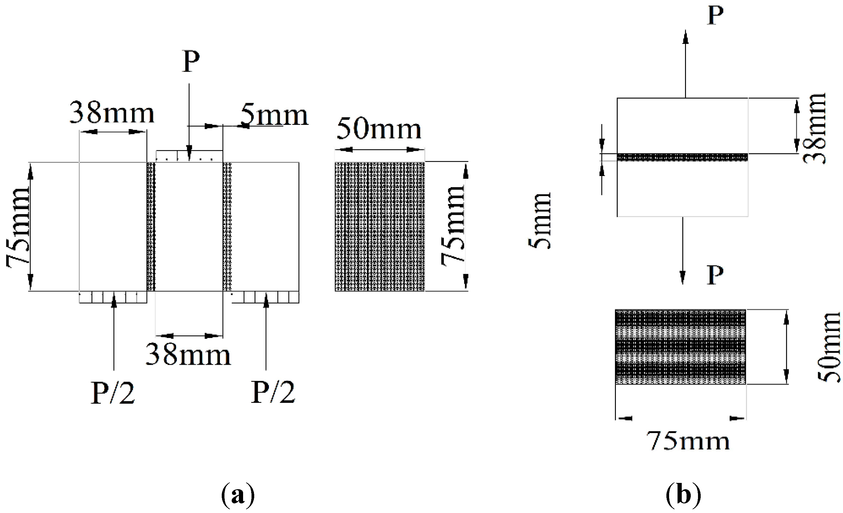
Table 2. Shear strength and bond strength of brick mortar assembly was determined by performing shear test and bond test using the test setup shown in
Figure 17a,b.
Table 2.
Material properties of masonry.
Table 2.
Material properties of masonry.
| Material Property | Diagonal Compression Test | Out-of-Plane Load Test | Units |
|---|
| Average compressive strength of bricks | 26.10 | 26.10 | MPa |
| Average compressive strength of mortar | 1.03 | 1.16 | MPa |
| Average compressive strength of masonry | 13.42 | 13.60 | MPa |
| Average Shear strength of mortar | 0.023 | 0.025 | MPa |
| Average bond strength of mortar | 0.0032 | 0.0043 | MPa |
Figure 17.
Test setup for masonry (a) shear test and (b) bond test.
Figure 17.
Test setup for masonry (a) shear test and (b) bond test.
6. Conclusions
Current experimental study gives a good basis for comparison and suitability of different retrofitting methods. FRP is an expensive material with high tensile strength but with low tensile failure strain ranging from 2%–4%, whereas PP-band is a low cost material with low tensile strength and higher tensile failure strain. Composite of FRP + PP-band has not only increased the initial strength and deformation capacity but also the residual strength of masonry wall panels. FRP and URM masonry panel has shown a brittle failure as compared to PP-band and FRP + PP-band retrofitted masonry panels. In the case of only FRP retrofitted masonry panels, once the FRP debonding started, it did not stop until complete detachment form the wall surface. This resulted in sudden drop in shear strength and breaking of masonry panels into several pieces. In the case of FRP + PP-band retrofitted panels, FRP was not completely detached because of the hindrance provided by PP-band at certain locations. This effect kept FRP attached on some parts of the masonry panel, which resulted in higher values of residual strength compared to only PP-band retrofitted masonry panels. Due to the holding effect of PP-band, the panels were capable of withstanding much bigger displacements as compared to only FRP retrofitted masonry panels.
In out-of-plane bending tests it is seen that application of PP-band along with the CFRP has changed the failure mode of FRP retrofitted masonry panels as initial drop in strength and separation of brick layers were not observed in FRP + PP-band retrofitted masonry panels. In FRP retrofitted panels, panels were broken in the form of longitudinal strips, but FRP + PP-band retrofitted masonry panels remained as single units during the entire loading history. In the case of FRP + PP-band retrofitted masonry panels, the initial failure of masonry panel was just like FRP retrofitted masonry panels due to debonding of FRP from the brick surface, but panels had sufficient residual strength and long deformation capacity.
In this study, different types of FRPs were selected to find the most suitable and appropriate type of FRP to be used with PP-band. Experimental results showed that in all types of FRP retrofitted panels, full strength of FRP was not utilized and higher strength and stiffness values of FRP have not played any important role as all types of FRP has shown almost similar increase in initial strength. Most suitable type of FRP is that which has minimum cost. Failure occurs either due to detachment of FRP from the brick surface or due to debonding of FRP and epoxy from the brick surface, which forces not using high quality and higher volumes of FRP, but to use strong epoxy or glue and bricks with good surface qualities. Current study has proven that FRP + PP-band composite is a high performance composite solution for seismic retrofitting of masonry structures and proposed retrofitting technique, using composite of FRP and PP-band is a very viable solution for seismic retrofitting of URM masonry structures.
Acknowledgments
The authors thankfully acknowledge the technical and financial support mainly provided by Meguro Laboratory, Institute of Industrial Science, University of Tokyo Japan and this work was also partially supported by the Deanship of Scientific Research at King Faisal University through its 13th annual project 13011.
Author Contributions
All authors tried their best to contribute effectively to perform and analyze this experimental work. Saleem Muhammad Umair and Kimiro Meguro planned experimental scheme and methods. Models were constructed and retrofitted by Saleem Muhammad Umair. Muneyoshi Numada and Kimiro Meguro supervised the experimental work and Muhammad Nasir Amin contributed for the analysis of results and failure patterns.
Conflicts of Interest
The authors declare no conflict of interest.
References
- Shrive, N.G. The use of fiber reinforced polymers to improve seismic resistance of masonry. Constr. Build. Mater. 2006, 20, 269–277. [Google Scholar]
- Yoshimura, M.; Meguro, K. Proposal of retrofitting promotion system for low earthquake resistant structures in earthquake prone countries. In Proceedings of the 13th World Conference on Earthquake Engineering, Vancouver, BC, Canada, 1–6 August 2004.
- Bruneau, M. State-of-the-art report on seismic performance of unreinforced masonry buildings. J. Struct. Eng. 1994, 120, 230–251. [Google Scholar] [CrossRef]
- Lotfi, H.R.; Shing, P.B. An interface model applied to fracture of masonry structures. J. Struct. Eng. 1994, 120, 63–80. [Google Scholar] [CrossRef]
- Calvi, G.M.; Bolognini, D. Seismic response of reinforced concrete frames infilled with masonry panels weakly reinforced. J. Earthq. Eng. 2001, 5, 153–185. [Google Scholar]
- Magenes, G.; Calvi, G.M. In-plane seismic response of brick masonry walls. Earthq. Eng. Struct. Dyn. 1997, 26, 1091–1112. [Google Scholar] [CrossRef]
- Velazquez-Dimas, J.I.; Ehsani, M.R. Modeling out-of-plane behavior of URM walls retrofitted with fiber composites. J. Compos. Constr. 2000, 4, 172–181. [Google Scholar] [CrossRef]
- Elgawady, M.; Lestuzzi, P.; Badoux, M. A review of conventional seismic retrofitting for URM. In Proceedings of the 13th Internatonal Brick/Block Masonry Conference, Amsterdam, The Netherlands, 4–7 July 2004.
- Schwegler, G. Masonry construction strengthened with fiber composites in seismically endangered zones. In Proceedings of the 10th European Conference on Earthquake Engineering, Vienna, Austria, 28 August–2 September 1994; pp. 467–476.
- Gilstrap, J.M.; Dolan, C.W. Out-of-plane bending of FRP reinforced masonry walls. Compos. Sci. Technol. 1998, 58, 1277–1284. [Google Scholar] [CrossRef]
- Ehsani, M.R.; Saadatmanesh, H.; Velazquez-Dimas, J.I. Behavior of retrofitted URM walls under simulated earthquake loading. J. Compos. Constr. 1999, 3, 134–142. [Google Scholar] [CrossRef]
- Valluzzi, M.R.; Tinazzi, D.; Modena, C. Shear behavior of masonry panels strengthened by FRP laminates. Constr. Build. Mater. 2002, 16, 409–416. [Google Scholar] [CrossRef]
- Zhao, T.; Zhang, C.J.; Xie, J. Experimental study on earthquake strengthening of brick walls with continuous carbon fibre sheet. Mason. Int. 2003, 16, 21–25. [Google Scholar]
- Stratford, T.; Pascale, G.; Manfroni, O.; Bonfiglioli, B. Shear strengthening masonry panels with sheet GFRP. J. Compos. Constr. 2004, 8, 434–443. [Google Scholar] [CrossRef]
- Tan, K.H.; Patoary, M.K.H. Strengthening of masonry walls against out-of plane loads using fiber-reinforced polymer reinforcement. J. Compos. Constr. 2004, 8, 79–87. [Google Scholar] [CrossRef]
- ElGawady, M.A.; Lestuzzi, P.; Badoux, M. In-plane seismic response of URM walls upgraded with FRP. J. Compos. Constr. 2005, 9, 524–534. [Google Scholar] [CrossRef]
- Prota, A.; Marcari, G.; Fabbrocino, G.; Manfredi, G.; Aldea, C. Experimental in-plane behavior of tuff masonry strengthened with cementitious matrix-grid composites. J. Compos. Constr. 2006, 10, 223–233. [Google Scholar] [CrossRef]
- Marcari, G.; Manfredi, G.; Prota, A.; Pecce, M. In-plane shear performance of masonry panels strengthened with FRP. Composites 2007, 38, 887–901. [Google Scholar] [CrossRef]
- Alcaino, P.; Santa-Maria, H. Experimental response of externally retrofitted masonry walls subjected to shear loading. J. Compos. Constr. 2008, 12, 489–498. [Google Scholar] [CrossRef]
- Willis, C.R.; Yang, Q.; Seracino, R.; Griffith, M.C. Damaged masonry walls in two-way bending retrofitted with vertical FRP strips. Constr. Build. Mater. 2009, 23, 1591–1604. [Google Scholar] [CrossRef]
- Roca, P.; Araiza, G. Shear response of brick masonry small assemblages strengthened with bonded FRP laminates for in-plane reinforcement. Constr. Build. Mater. 2010, 24, 1372–1384. [Google Scholar] [CrossRef]
- Santa-Maria, H.; Alcaino, P. Repair of in-plane shear damaged masonry walls with external FRP. Constr. Build. Mater. 2011, 25, 1172–1180. [Google Scholar] [CrossRef]
- Luciano, R.; Sacco, E. Damage of masonry panels reinforced by FRP sheets. Int. J. Solids Struct. 1998, 35, 1723–1741. [Google Scholar] [CrossRef]
- Mayorca, P.; Meguro, K. Efficiency of polypropylene bands for the strengthening of masonry structures in developing countries. In Proceedings of the 5th International Summer Symposium, Japan Society of Civil Engineers (JSCE), Tokyo, Japan, 26 July 2003; pp. 125–128.
- Drozdov, A.D.; Al-Mulla, A.; Gupta, R.K. Structure-property relations for polymer melts: Comparison of linear low-density polyethylene and isotactic polypropylene. Adv. Mater. Res. 2012, 1, 245–268. [Google Scholar] [CrossRef]
- Sathiparan, N.; Mayorca, P.; Nesheli, K.; Ramesh, G.; Meguro, K. In-plane and out-of-plane behavior of PP-band retrofitted masonry panels. In Proceedings of the 4th International Symposium on New Technologies for Urban Safety of Mega Cities in Asia, Singapore, 18–19 October 2005; pp. 231–240.
- Meguro, K.; Mayorca, P.; Sathiparan, N. Shaking table test on timber masonry house models retrofitted with PP-band meshes. In Proceedings of the 7th Intertional Symposium on New Technologies for Urban Safety of Mega Cities in Asia, Beijing, China, 21–22 October 2008.
- Dar, A.M.; Saleem, M.U.; Numada, M.; Meguro, K. Experiment study on reduction of PP-band mesh connectivity for retrofitting of masonry structure. Bull. Earthq. Resist. Struct. 2014, 47, 67–80. [Google Scholar]
- Sathiparan, N.; Meguro, K. Seismic behavior of low earthquake-resistant arch-shaped roof masonry houses retrofitted by PP-band meshes. ASCE Pract. Period. Struct. Des. Constr. 2012, 17, 54–64. [Google Scholar] [CrossRef]
- Sathiparan, N.; Mayorca, P.; Meguro, K. Shake table tests on one-quarter scale models of masonry houses retrofitted with PP-band mesh. Earthq. Spectr. 2012, 28, 277–299. [Google Scholar] [CrossRef]
- Turco, V.; Secondin, S.; Morbin, A.; Valluzzi, M.R.; Modena, C. Flexural and shear strengthening of un-reinforced masonry with FRP bars. Compos. Sci. Technol. 2006, 66, 289–296. [Google Scholar] [CrossRef]
- Ghiassi, B.; Xavier, J.; Oliveira, D.V.; Kwiecien, A.; Lourenço, P.B.; Zajac, B. Evaluation of the bond performance in FRP-brick components re-bonded after initial delamination. Compos. Struct. 2015, 123, 271–281. [Google Scholar] [CrossRef]
- Ghiassi, B.; Xavier, J.; Oliveira, D.V.; Lourenço, P.B. Application of digital image correlation in investigating the bond between FRP and masonry. Compos. Struct. 2013, 106, 340–349. [Google Scholar] [CrossRef] [Green Version]
- Ghorbani, R.; Matta, F.; Sutton, M.A. Full-field deformation measurement and crack mapping on confined masonry walls using digital image correlation. Exp. Mech. 2015, 55, 227–243. [Google Scholar] [CrossRef]
- Santa-Maria, H.; Alcaino, P.; Luders, C. Experimental response of masonry walls externally reinforced with carbon fibers. In Proceedings of the 8th US National Conference on Earthquake Engineering, San Francisco, CA, USA, 18–22 April 2006.
- Mahmood, H.; Russell, A.P.; Ingham, J.M. Laboratory testing of unreinforced masonry walls retrofitted with glass FRP sheets. In Proceedings of the 14th International Brick/Block Masonry Conference, Sydney, Australia, 17–20 February 2008.
- Nardone, F.; Protra, A.; Mafredi, G. Design criteria for FRP seismic strengthening of masonry walls. In Proceedings of the 14th World Conference on Earthquake Engineering, Beijing, China, 12–17 October 2008.
- Mahmood, H.; Ingham, J.M. Diagonal compression testing of FRP retrofitted unreinforced clay brick masonry panels. J. Compos. Constr. 2011, 15, 810–820. [Google Scholar] [CrossRef]
- Mayorca, P.; Meguro, K. Proposal of a methodology to design PP-band meshes to retrofit low earthquake resistant houses. In Proceedings of the 6th International Symposium on New Technologies for Urban Safety of Megacities in Asia, Dhaka, Bangladesh, 9–10 December 2007.
- Sinan, A.; Anil, O.; Emin, M.K.; Mustafa, K. An experimental study on strengthening of masonry infilled RC frames using diagonal CFRP strips. Composites 2008, 39, 680–693. [Google Scholar] [CrossRef]
- Ozsayin, B.; Yilmaz, E.; Ispir, M.; Ozkaynak, H.; Yuksel, E.; Ilki, A. Characteristics of CFRP retrofitted hollow brick infill walls of reinforced concrete frames. Constr. Build. Mater. 2011, 25, 4017–4024. [Google Scholar] [CrossRef]
- Standard Test Methods for Sampling and Testing Brick and Structural Clay Tile; ASTM C67–03a; ASTM International: West Conshohocken, PA, USA, 2003.
- Standard Test Method for Compressive Strength of Hydraulic Cement Mortars (Using 2-in or [50-mm] Cube Specimen); ASTM C109/C109M-02; ASTM International: West Conshohocken, PA, USA, 2002.
- Standard Test Methods for Compressive Strength of Masonry Prisms; ASTM C1314–03a; ASTM International: West Conshohocken, PA, USA, 2003.
© 2015 by the authors; licensee MDPI, Basel, Switzerland. This article is an open access article distributed under the terms and conditions of the Creative Commons Attribution license (http://creativecommons.org/licenses/by/4.0/).


