Article

Residual Axial Capacity Comparison of CFFT and RC Bridge Columns after Fire

1
Structures Department, HNTB Corporation, Newark, NJ 07102, USA
2
Department of Civil and Environmental Engineering, University of Connecticut, Storrs, CT 06269, USA
*
Author to whom correspondence should be addressed.
Polymers 2015, 7(5), 876-895; https://doi.org/10.3390/polym7050876
Submission received: 21 March 2015 / Revised: 20 April 2015 / Accepted: 24 April 2015 / Published: 5 May 2015
(This article belongs to the Collection Fiber-Reinforced Polymer Composites in Structural Engineering)

Abstract

:
The fire performance of protected concrete-filled fiber reinforced polymer (FRP) tube (CFFT) and conventional reinforced concrete (RC) bridge columns is studied through two phases of experimental research comprised of fire exposure and residual axial capacity tests. Two one-fifth scale CFFT columns and two one-fifth scale conventional RC columns having similar axial and flexural capacities were subjected to two durations of extreme temperature exposure. The CFFT columns were protected by the Tyfo® CFP fire protection system during the experiments. Subsequently, the post-fire robustness of the columns was quantified by measuring the residual axial capacity characteristics of each column. The protected CFFT columns exhibited superior axial strength and stiffness retention compared to the RC columns after fire exposure.

Graphical Abstract

1. Introduction

Between 1980 and 2012, 30 highway bridges failed due to fire hazard exposure in the United States (US). In the same time period, only 20 US bridges were reported to have failed due to earthquakes [1]. Although hazards such as earthquakes, hurricanes, and floods can result in undeniably catastrophic life and monetary losses as evidenced by the numbers reported by Li et al. [2], fire is one of the most severe environmental hazards to built infrastructure causing more bridge failures over the last three decades than earthquakes. Despite this fact, there are no specific American Association of State Highway Transportation Officials (AASHTO) requirements for the protection of bridge elements against fire [3]. Although AASHTO does not provide fire specifications for bridge elements, the National Fire Protection Association (NFPA) provides a standard for the protection of tunnels, bridges, and other limited access highways. Provision 6.3.2 of NFPA 502 explicitly states that critical structural members shall be protected from collisions and exposure to high-temperatures which can result in dangerous weakening or complete collapse of a bridge or elevated highway [4]. This study compares the post-fire robustness of unprotected, conventionally constructed reinforced concrete (RC) bridge columns and protected, innovative concrete-filled fiber reinforced polymer (FRP) tube (CFFT) bridge columns.
According to the American Society of Civil Engineers (ASCE) Report Card on America’s Infrastructure [5], one-fourth of the nation’s bridges are either structurally deficient or obsolete. Increased traffic demands combined with this deteriorated state of the nation’s bridges increases their vulnerability to many types of natural and manmade hazards including but not limited to earthquakes, corrosion, blasts, storm surge, and fires. Columns are critical elements of bridge infrastructure, and their proximity to hazardous materials transported on adjacent roadways or spanned waterways make bridge columns especially vulnerable to vehicle/vessel collisions and fire hazards. Most fire studies dedicated to bridge elements are focused on steel superstructures because the high thermal conductivity of steel material makes it inherently less fire resistant than concrete columns. However, the vulnerability of steel superstructures to fire should not overshadow the importance of the post-fire performance of substructure elements.
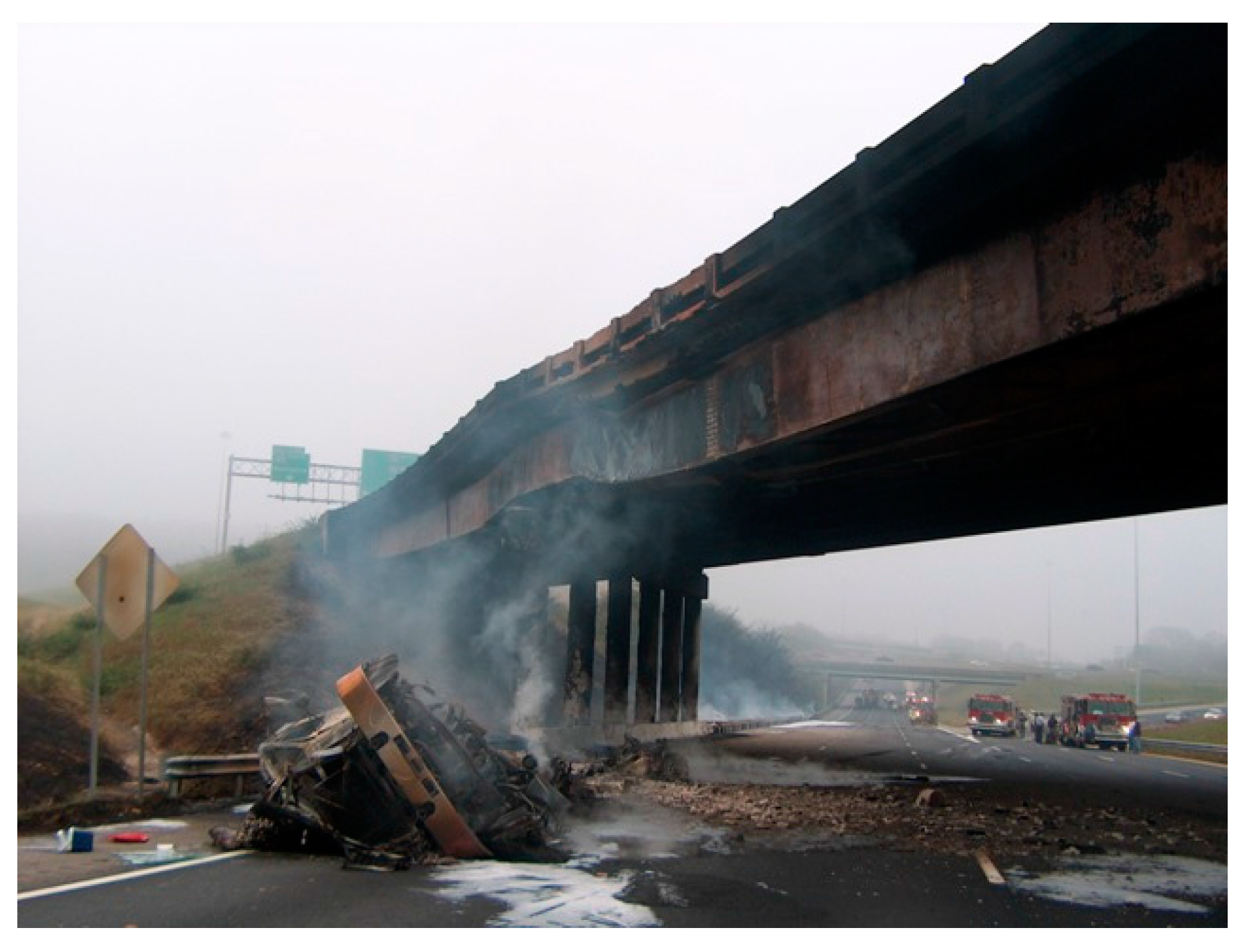
After extreme fire events, damage to bridge elements is often visually evident as shown in 
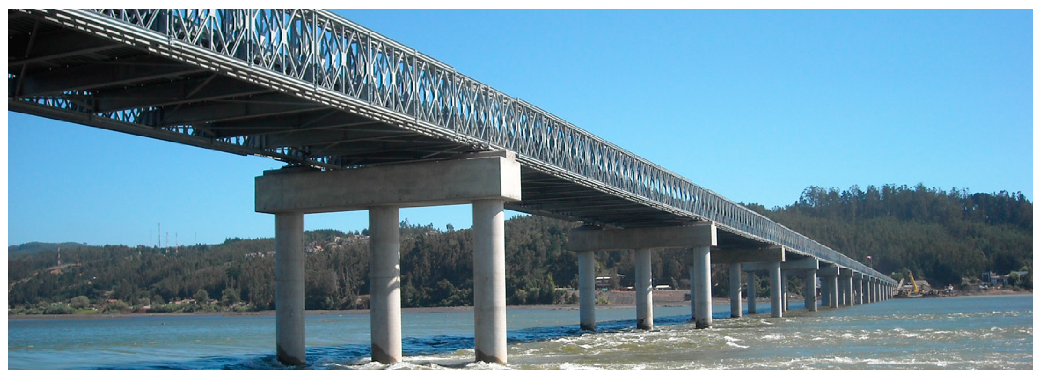
Figure 1. In other instances, a fire event may cause structural degradation with minimal outward signs of damage. This is especially true for concrete components, which can be problematic for officials faced with the emergency decision to keep a bridge in-service or order a costly bridge closure after a fire event. Columns are critical for keeping a bridge open to regular traffic or emergency responders. Even if a bridge’s superstructure is significantly damaged, temporary structures, like the one shown in Figure 2, may be rapidly installed to restore service if the columns are able to retain their capacity.
Figure 1. Visible bridge damage due to vehicular fire.
Polymers 07 00876 g001
Figure 2. Emergency bridge over Bio Bio River in Concepciόn, Chile.
Polymers 07 00876 g002
Many fire studies have been conducted on several different types of columns. However, most are focused on the performance of building columns. A series of studies conducted by Garlock and Quiel examines the performance of steel building columns subjected to fire. In one study, Garlock and Quiel [6] use axial load and moment interaction curves to show that thermal gradients can have a significant effect on the yield capacity of beam-columns. In another, Quiel and Garlock [7] use three different analytical models to determine the response of steel beam columns with thermal gradients. Agarwal and Varma [7] completed a finite element and numerical analysis study of the importance of gravity columns to the overall stability of steel buildings. Han et al. [8] performed an experimental fire performance study of concrete-filled stainless steel tube columns directed toward off-shore structural applications.  Kodur et al., has conducted several studies on the effects of fiber reinforcement, fly ash, and tie configuration on the fire performance of high-strength concrete (HSC) columns [9,10,11,12]. There have also been a significant number of studies conducted on fiber reinforced polymer (FRP) confined concrete columns, including those conducted by Green et al. [13], Chowdury et al. [14], Cree et al. [15], Gefu et al. [16], Bisby et al. [17] and Kodur et al. [18] to name a few.
A fair amount of research has also been dedicated to the study of fire effects in bridges. Alos-Moya et al. [19] conducted a finite element (FE) and computational fluid dynamic (CFD) analysis of the Interstate 65 (I-65) overpass in Birmingham, Alabama that failed due to fire in 2002. The resulting numerical models were able to accurately replicate the performance and failure of the plate girder bridge. Garlock et al. [20] compiled a comprehensive review of fire hazards in bridges. The study reviewed major fire incidents, past case studies, and several assessment and repair methodologies. The review identified several literature gaps related to fire hazards and bridges. Performing experimental studies and determining post-fire strength were among the areas reported to be in need of further research in the findings.
The study presented herein aims to fulfill some of these research needs by experimentally quantifying and comparing the residual axial capacities of conventionally constructed RC and protected CFFT bridge columns after two distinct durations of fire exposure. The presented study stems from recent studies conducted on RC and CFFT bridge columns. Recent studies have proven the CFFT system a viable alternative to conventional RC columns for bridges vulnerable to earthquake and blast hazards [21,22,23,24,25,26,27,28]. Additionally, the CFFT system has shown that it can provide increased corrosion resistance and construction benefits including accelerated construction times and increased workzone safety [26]. This study aims to extend the application of the CFFT system to instances where fire poses a threat to the performance of bridge columns.
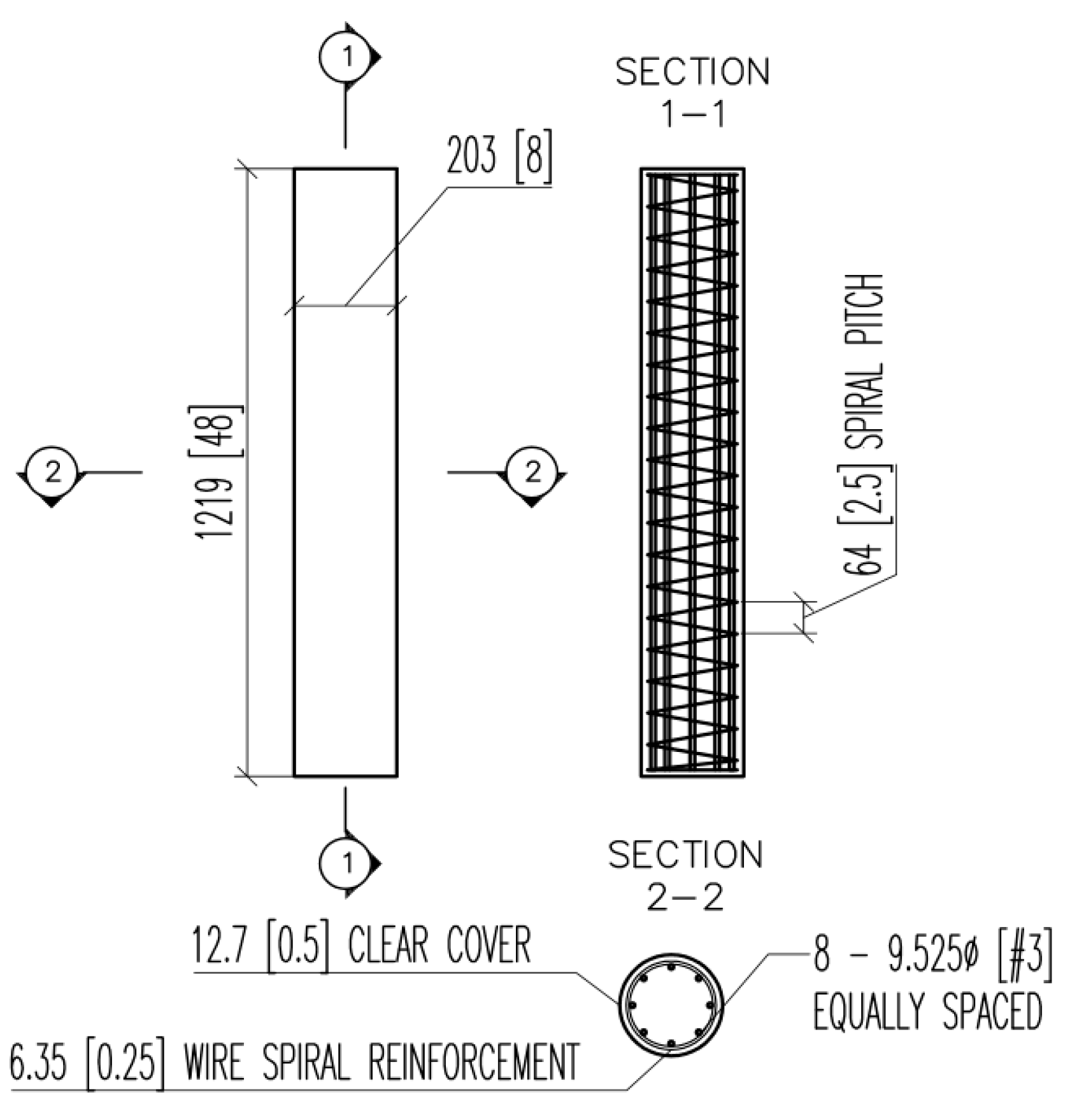
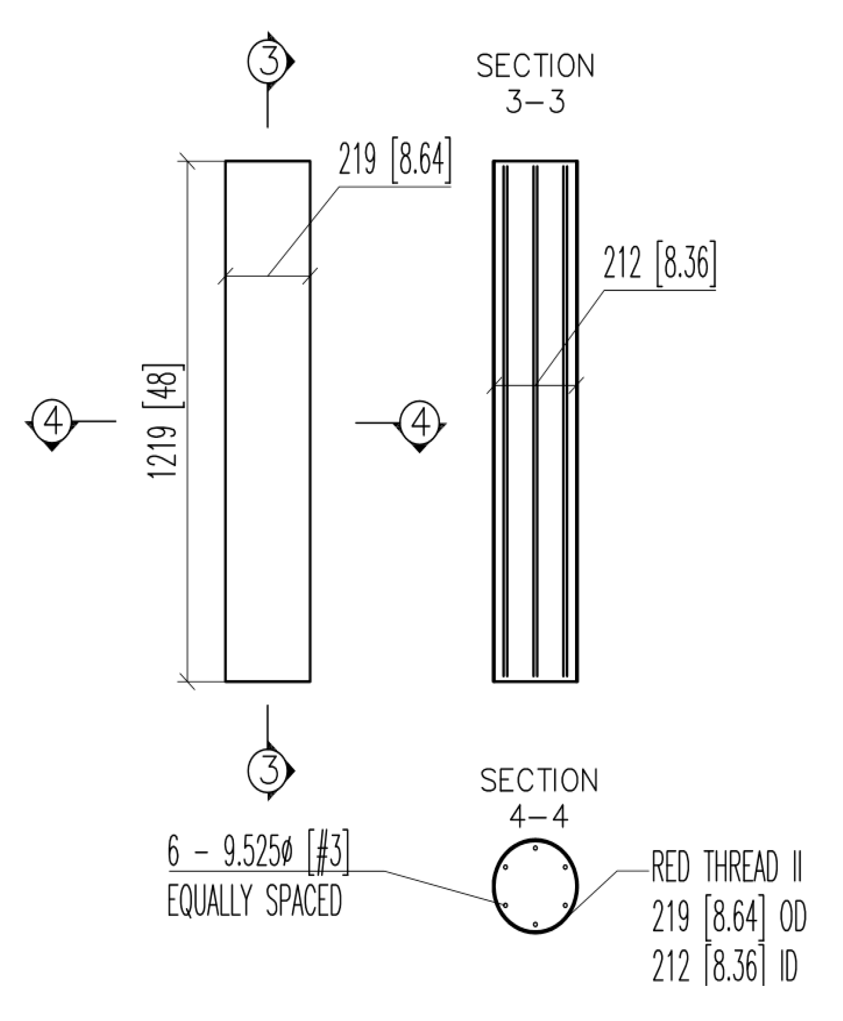
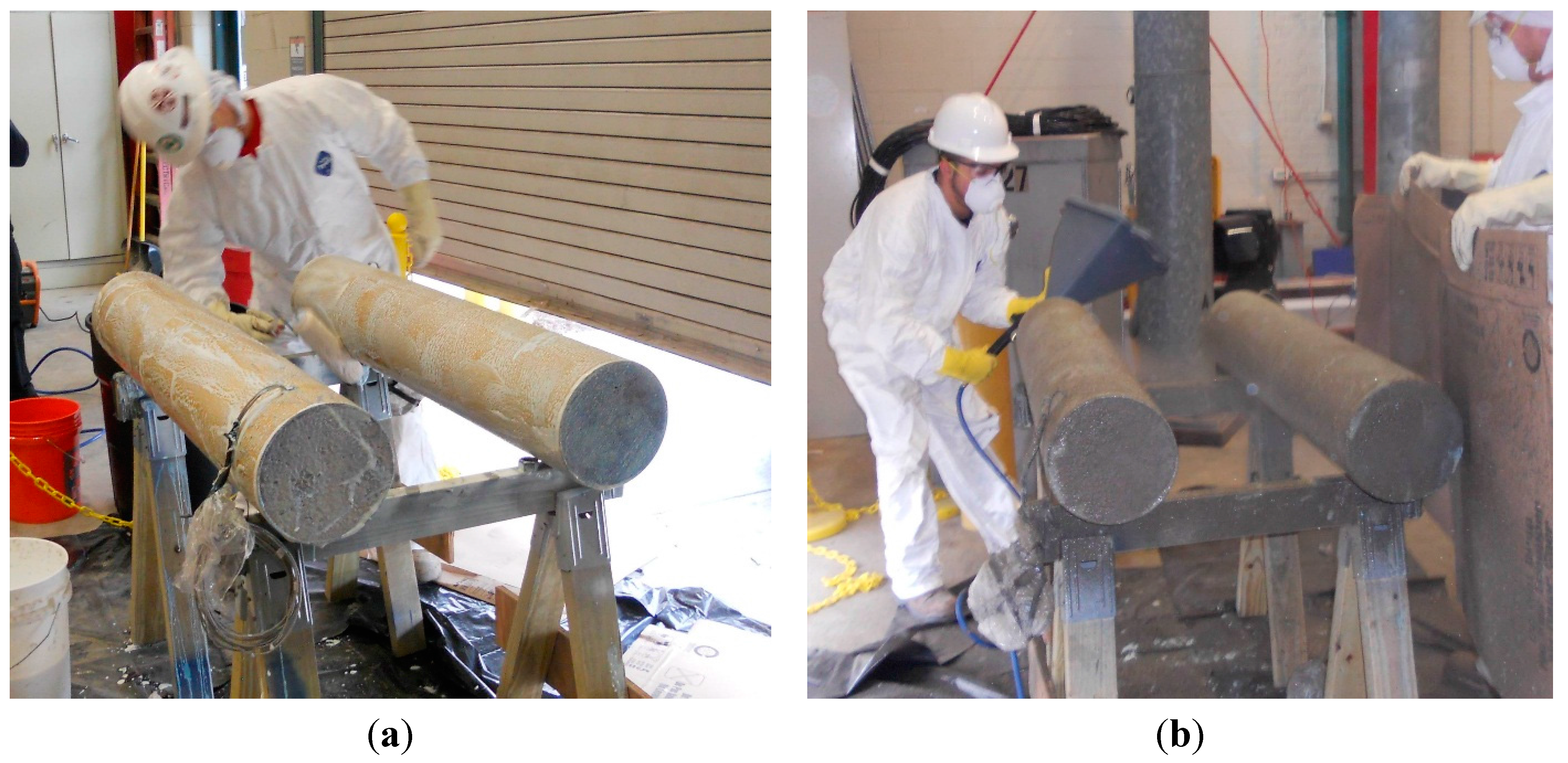
For this study, two experimental fire exposure tests, resulting in material degradation but not complete failure, were conducted on four one-fifth scale bridge column specimens. Two of the column specimens were designed and constructed as conventional RC columns. The other two specimens were designed as CFFTs with similar dimensions and capacity to replicate those that would be used in comparable bridge designs. A fire resistant system was applied to the surface of each CFFT column to protect the FRP tube which is the main reinforcing mechanism for CFFTs.
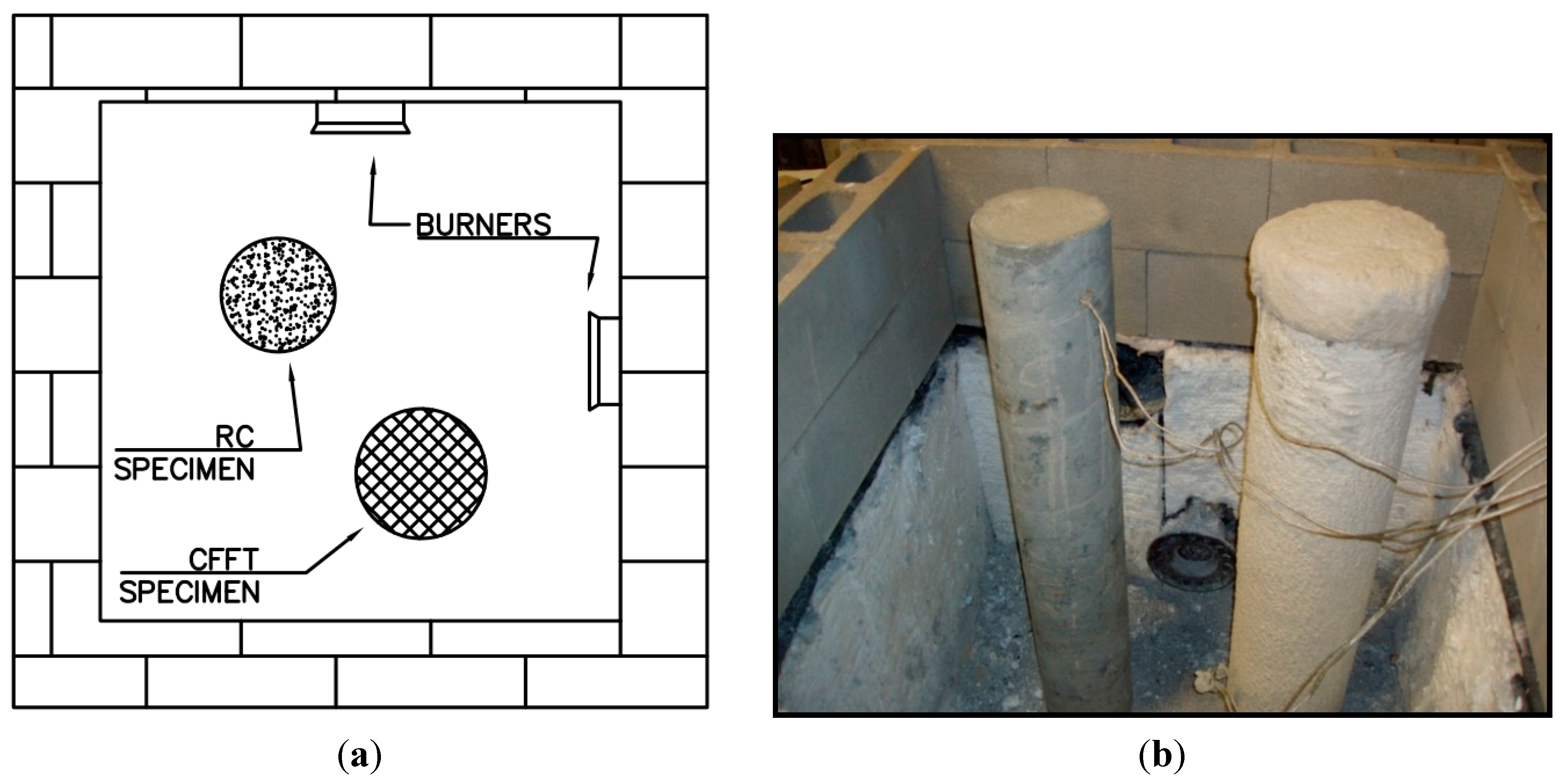
The four one-fifth scale specimens were tested two at a time. First, one RC and one CFFT column were simultaneously exposed to more than two hours of extreme heat. Next, the other two specimens, one RC and one CFFT, were simultaneously exposed for one hour. Both durations of exposure caused the concrete temperatures in the RC columns to rise above typical limits for material degradation. However, neither RC column specimen exhibited outward signs of damage. Although the FRP tube did exhibit discoloration after exposure, the protection system applied to the CFFT columns kept the concrete temperatures below material degradation limits.
After the two fire experiments, the four fire-damaged columns were loaded axially to failure to obtain their post-fire axial performance characteristics. Residual axial capacity was chosen as the post-fire performance measure because bridge columns are primarily axial load carrying members. In addition to the fire-damaged specimens, two undamaged benchmark columns, one of each type, having the same design and constructed with the same materials as the fire exposed specimens were also tested axially to obtain the undamaged axial capacity characteristics of each column type. The residual axial capacity characteristics of the four fire exposed columns were compared to each other as well as to their respective undamaged benchmark specimens to quantify the post-fire performance of RC and CFFT bridge columns. While the fire damaged RC columns showed no outward signs of damage, both specimens exhibited losses in axial strength and stiffness. Conversely, the protected CFFT columns saw slight gains in capacity after both durations of fire, and exhibited less stiffness degradation than their RC counterparts.

2. Experimental Section

2.1. Design of Column Specimens

The primary constraint for the design of the column specimens was the 1779 kN (400 kip) capacity of the load frame at the University of Connecticut (UConn) which was used to perform the axial capacity tests of the fire damaged and undamaged benchmark columns. Preliminary cross-section analyses of scaled RC and CFFT bridge columns showed that one-fifth scale specimens would not have axial strength exceeding the capacity of the load frame.

2.1.1. Reinforced Concrete (RC) Columns

The design of the RC column specimens was derived from a two-span high bridge design example developed by Modjeski and Masters, Inc. [29]. The diameter and height of the prototype column were geometrically scaled by one-fifth. To minimize scaling effects in the experiments, comparable longitudinal and lateral reinforcement ratios were incorporated. For the same reason a reduced aggregate size of 9.53 mm (3/8 inch (in.)) was selected for construction. AASHTO Specifications for Seismic Zone 1 [30] were checked for minimum and maximum longitudinal and transverse reinforcement limits.
The one-fifth scale columns had a design height of 1.22 m (48 in.) and diameter of 203 mm (8 in.). The columns were longitudinally reinforced with eight Grade (Gr.) 60 #3 (9.53 mm (0.375 in.) diameter) bars cut to 1.19 m (47 in.) to provide 12.7 mm (0.5 in.) of clear cover on either end. The longitudinal reinforcement ratio, ρs, was equal to 1.75%. Spiral reinforcement pre-fabricated from 6.35 mm (0.25 in.) diameter smooth wire was used as transverse reinforcement for the RC specimens. The outer spiral diameter was specified as 178 mm (7 in.) to provide 12.7 mm (0.5 in.) of clear cover to the column surface. Drawings of the RC column design are shown in Figure 3.
Figure 3. Reinforced concrete (RC) Column Design Drawing.
Polymers 07 00876 g003
To ensure that the one-fifth scale RC design would have axial capacity less than 1779 kN (400 kip), the column cross section was modeled in XTract [31] prior to construction. The resulting axial load-strain curve for the RC specimens is shown in Figure 4. The ultimate capacity of the column was expected to be 1192 kN (268 kip) falling within the constraints of the UConn load frame.
Figure 4. XTract axial load-strain curve for RC and concrete-filled fiber reinforced polymer (FRP) tube (CFFT) columns.
Polymers 07 00876 g004

2.1.2. Concrete-Filled Fiber Reinforced Polymer (FRP) Tube (CFFT) Columns

A first edition AASHTO guide specification for the design of CFFTs as axial and flexural members [32] was released in early 2013. However, the guide specification was not available at the time the CFFT specimens used in this study were designed. Therefore, XTract [31] was used to determine a CFFT design with similar axial capacity to the RC design while still complying with the AASHTO requirements for the minimum amount of longitudinal steel reinforcement. Section 5.7.4.2. of the AASHTO LRFD Bridge Design Specifications [30] limits the minimum number of longitudinal reinforcing bars to six and the minimum longitudinal reinforcement ratio to 1%.
The CFFT design consisted of a Red Thread® II pipe manufactured by National Oilwell Varco (NOV) Fiberglass Systems (FGS) [33]. The pipe had outside and inside diameters of 219 mm (8.64 in.) and 212 mm (8.36 in.), respectively, resulting in a thickness of 3.56 mm (0.14 in.). The composite pipe is made of glass fibers aligned at 55° with respect to the longitudinal axis. This particular fiber alignment provides both longitudinal and hoop strength to the column. Thus, no steel transverse reinforcement was included in the CFFT design, and the longitudinal reinforcement was reduced to six Gr. 60 #3 bars (9.525 mm (0.375 in.) diameter), resulting in a reinforcement ratio of 1.12%. Drawings of the CFFT column design are shown in Figure 5.
Figure 5. CFFT column design drawing.
Polymers 07 00876 g005
The axial load-strain curve for the CFFT column resulting from the XTract analysis is shown in Figure 4 The tri-linear FRP material model presented by Zaghi et al. [26] was used to model the FRP tube, and the FRP confined concrete model described by Saiidi [34] was used to model the confined concrete core. The resulting ultimate axial capacity obtained from XTract was 1758 kN (395 kip). Because the FRP tube material was modeled as having a nearly linear stress-strain relationship, the CFFT column has a large post-yield stiffness. However, some softening was expected to occur during the axial test experiments; thus, the axial capacity of the CFFT column would be within the limits of the UConn test frame.

2.2. Specimen Construction and Material Properties

A wood frame was constructed to hold the sonotube forms and FRP tubes for simultaneous construction of the RC and CFFT columns. The framework used to hold the columns plumb is shown in Figure 6. The additional columns shown in this figure were used for blast experiments performed by UConn. The blast experiments are not discussed herein, but detailed information regarding the blast experiments can be found in Echevarria et al. [21,22,23]. The steel reinforcement for the columns was placed inside their respective tubes, and spacers were used to maintain clear cover between the steel and column surfaces. All of the columns were cast from a single batch of concrete with a specified compressive strength, f’c, of 27.6 MPa (4 ksi) and maximum aggregate size of 9.53 mm (0.375 in.). The concrete was delivered by truck, poured into the tubes from the top down, and consolidated using vibratory methods.
Figure 6. Wooden framework for column construction.
Polymers 07 00876 g006
At the time of column construction, 18 76 × 152 mm (3 × 6 in.) cylinders were cast to obtain concrete material properties at 28 days, 100 days, and one year. Samples of the longitudinal and transverse reinforcement were also saved to obtain the tensile properties for the steel material. The mechanical properties of the steel and concrete determined through material testing are summarized in Table 1. To view the complete stress–strain relationships of the materials refer to Echevarria et al. [22].
Table 1. Mechanical properties of concrete and steel materials.
MaterialMPa (ksi)
28 days concrete compressive strength23.0 (3.33)
100 days concrete compressive strength23.4 (3.39)
One year concrete compressive strength32.3 (4.67)
Steel rebar yield stress405 (58.7)
Steel rebar ultimate stress646 (93.7)
Steel spiral yield stress542 (78.6)
Steel spiral ultimate stress623 (90.4)
The material properties for the FRP tube were obtained from the manufacturer’s technical information. Table 2 summarizes the properties provided by the technical brochure at 24 °C (75 °F) and 99 °C (210 °F) [33]. For most civil engineering applications, only the properties at 24 °C (75 °F) are of concern, but because this study is focused on the performance of CFFTs after exposure to extreme heat, the properties at the higher temperature are also included for reference.
Table 2. Mechanical properties of FRP tube.
Mechanical Property75 °F (24 °C) ksi (MPa)210 °F (99 °C) ksi (MPa)
Ultimate tensile stress71.0 (10.3)53.0 (7.7)
Tensile modulus of elasticity12,550 (1820)8,343 (1210)
Ultimate compressive stress228 (33.0)134 (19.4)
Compressive modulus of elasticity8,687 (1260)4,137 (600)
Ultimate bending stress159 (23.0)110 (16.0)
Bending modulus of elasticity10,066 (1460)6,630 (960)
Ultimate hoop stress234 (34.0)300 (43.5)

2.3. Instrumentation and Fire Protection System

Each of the four columns was instrumented with two type K Omega® high temperature ceramic insulation thermocouples with Inconel® overbraid [35]. The thermocouples were rated for temperatures as high as 1090 °C. Both thermocouples were placed at midspan along the length of each column. One thermocouple was fastened to one of the longitudinal bars to record temperatures at the level of the steel reinforcement, and the other was suspended at the center of each column to record core concrete temperatures as shown in Figure 7. Five additional type K thermocouples owned by the fire testing facility were used to record the furnace temperature as well as the ambient temperature of the laboratory.
Figure 7. Thermocouples installed within each column specimen.
Polymers 07 00876 g007
Because FRP materials are vulnerable to extreme temperatures [13,14,15,16,17,20], the Tyfo® CFP System [36] was applied to the surface of the two CFFT columns. The Tyfo® CFP System is a three part, low profile system with the ability to provide up to a 4 h fire protection rating for square and circular columns per American Society for Testing and Materials (ASTM) E119, and a Class 1 flame and smoke rating per ASTM E84. The first layer of the system is the Tyfo® VG Primer. By weight, the primer is 52%–54% water, 46%–48% acrylic polymer, less than 0.05% residual monomers, and 0.2% (max.) aqua ammonia. The main purpose of the primer is to improve the bonding between FRP surface and the Tyfo® WR-AFP. The Tyfo® VG Dash Coat is the second component of the system. This layer provides a rough layer to the FRP surface to promote adhesion of the WR-AFP. The dash coat consists of Portland cement, both refined and exfoliated vermiculite, and minor amounts of other additives. This layer is similar to the final layer except that less vermiculite and more sand aggregate is used. The final layer is the Tyfo® WR-AFP. The parts of this layer, by weight, are 30%–40% Calcium Sulphate Hemi Hydrate (Gypsum), 30%–40% Portland cement, 25%–35% refined and exfoliated vermiculite, 10% ceramic fibers, and >10% cellulose and additives. Vermiculite is low density and favorable insulation properties. The material is also used for steel fireproofing and in the production of fire resistant gypsum plasterboard.
The fireproofing application process was completed by Fibrwrap® technicians. First, the Tyfo® VG Primer was generously applied to the surface area of the columns. Following the primer, the second component of the CFP System, the Tyfo® VG Dash Coat, was spray-applied in a non-continuous spatter pattern and was allowed to dry for approximately 30 min. As the final component of the system, the Tyfo® WR-AFP was applied in multiple layers to achieve a minimum thickness of 15.9 mm (0.625 in). To ensure the thickness of the fire protection reached 15.9 mm (0.625 in), the prescribed thickness was marked on a piece of wire which was inserted into the wet material as shown in Figure 8d. Photos of the complete application process are displayed in Figure 8.
Figure 8. Complete process of Tyfo® CFP fire protection system application: (a) VG primer application; (b) VG dash coat application; (c) WR-AFP application; (d) thickness check of system.
Polymers 07 00876 g008aPolymers 07 00876 g008b

2.4. Fire Test Setup and Parameters

The fire exposure tests were conducted at Guardian Fire Testing Facility in Buffalo, NY, USA. The laboratory’s furnace had a square footprint with inside dimensions of approximately 1.25 m (4 feet (ft)) and an adjustable height. The furnace was equipped with two natural gas burners located at the center of two adjacent walls as shown in Figure 9. After the columns were placed in the furnace, cinder blocks and insulation were used to adjust the height prior to placing the concrete slab cap.
Figure 9. (a) Plan-view schematic of test setup and (b) test set-up photo.
Polymers 07 00876 g009
Because the global objective of the fire experiments was to impart two levels of damage to each type of column, it was decided to conduct two durations of tests following the ASTM E119 testing procedure. The ASTM E119 temperature curve is shown in Figure 11. In the first and more severe test, one RC column and one CFFT column were subjected to two hours of extreme temperature following the ASTM E119 curve; this test will be referred to as the 2-Hr test hereafter. The second set of columns was subjected to one hour of the ASTM E119 temperature curve, and is referred to as the 1-Hr test, hereafter.

3. Results and Observations

3.1. General Observations

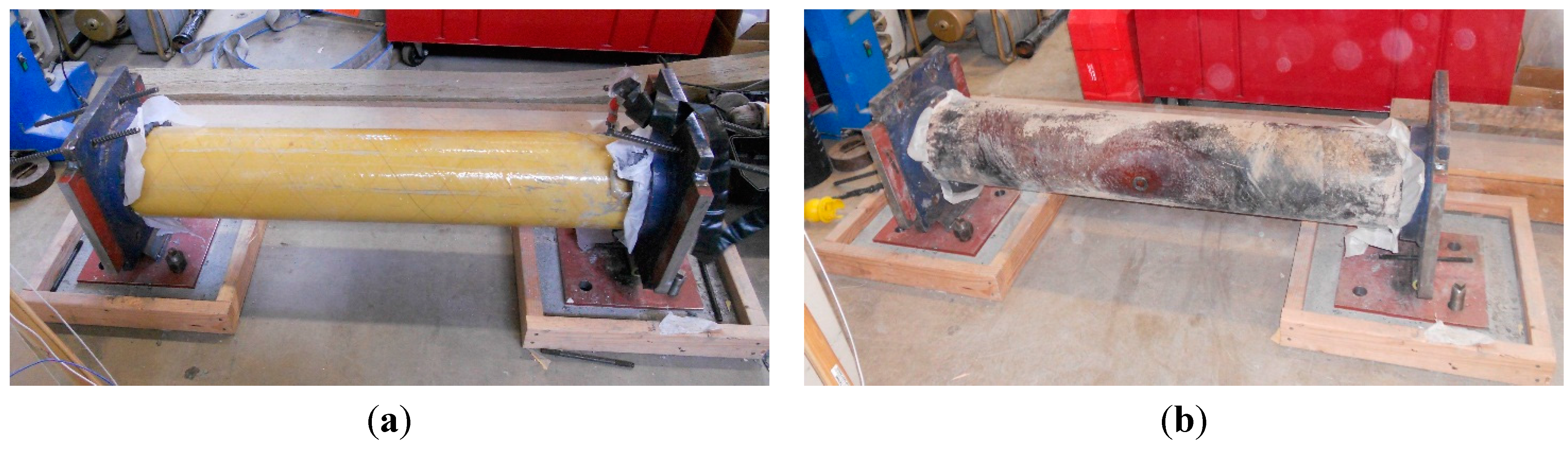
Upon removal from the furnace, none of the columns showed any significant outward signs of material degradation. The most noticeable signs of damage included discoloration of the FRP tube of the CFFT column after the 2-Hr test as shown in Figure 10b, and a change in the sound properties of the RC columns after both the 1- and 2-Hr durations. After the RC columns were removed from the furnace, a sound similar to that of a ceramic material was emitted when the surfaces of the columns were tapped rather than the typical sound expected when tapping a concrete column.
Figure 10. (a) Undamaged CFFT column and (b) discolored fire damaged CFFT column.
Polymers 07 00876 g010

3.2. Furnace Temperature Data

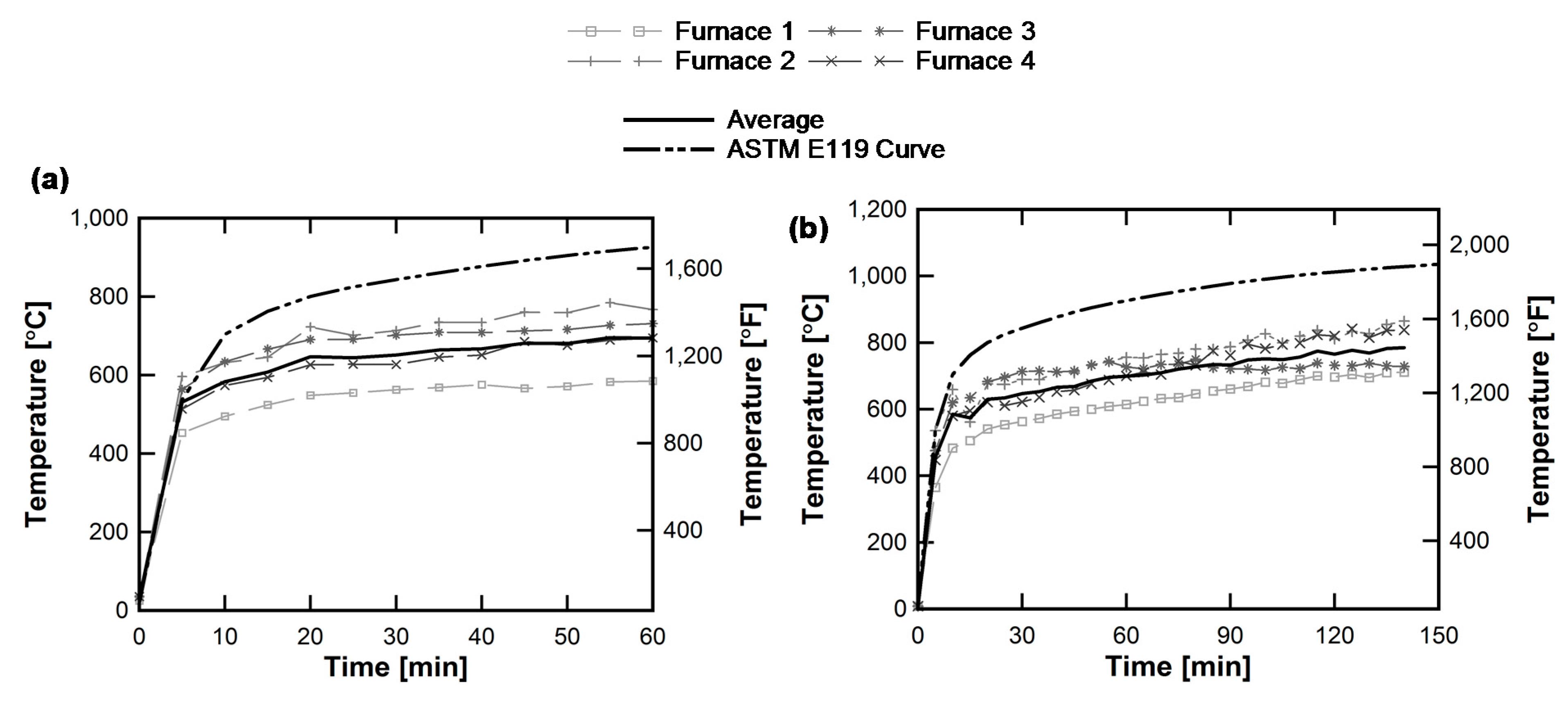
Furnace temperatures were recorded every five minutes throughout the duration of both tests, and the recorded temperature time histories are shown in Figure 11. Although the furnace burners were able to closely match the steep initial temperature increase rate of the ASTM E119 curve, the average furnace temperatures were about 200 °C below the ASTM curve for the majority of each test. The peak average furnace temperatures recorded were 696 °C and 786 °C for the 1-Hr and 2-Hr tests, respectively.
Because the furnace temperatures did not meet the ASTM standard, the 2-Hr test was extended by an additional 20 min. By prolonging the 2-Hr test, the total amount of temperature exposure, defined herein as the area beneath the temperature curve, was nearly 96,000 °C-min. This value falls within 10% of the total amount of temperature exposure for two hours following the ASTM E119 curve, or 105,000 °C-min. To maintain the differentiable levels of damage between the two tests, the furnace burners were extinguished at exactly 60 min for the 1-Hr test.
Figure 11. Furnace temperatures for (a) 1-Hr and (b) 2-Hr tests shown with the American Society for Testing and Materials (ASTM) E119 curve.
Polymers 07 00876 g011

3.3. Concrete Temperature Data

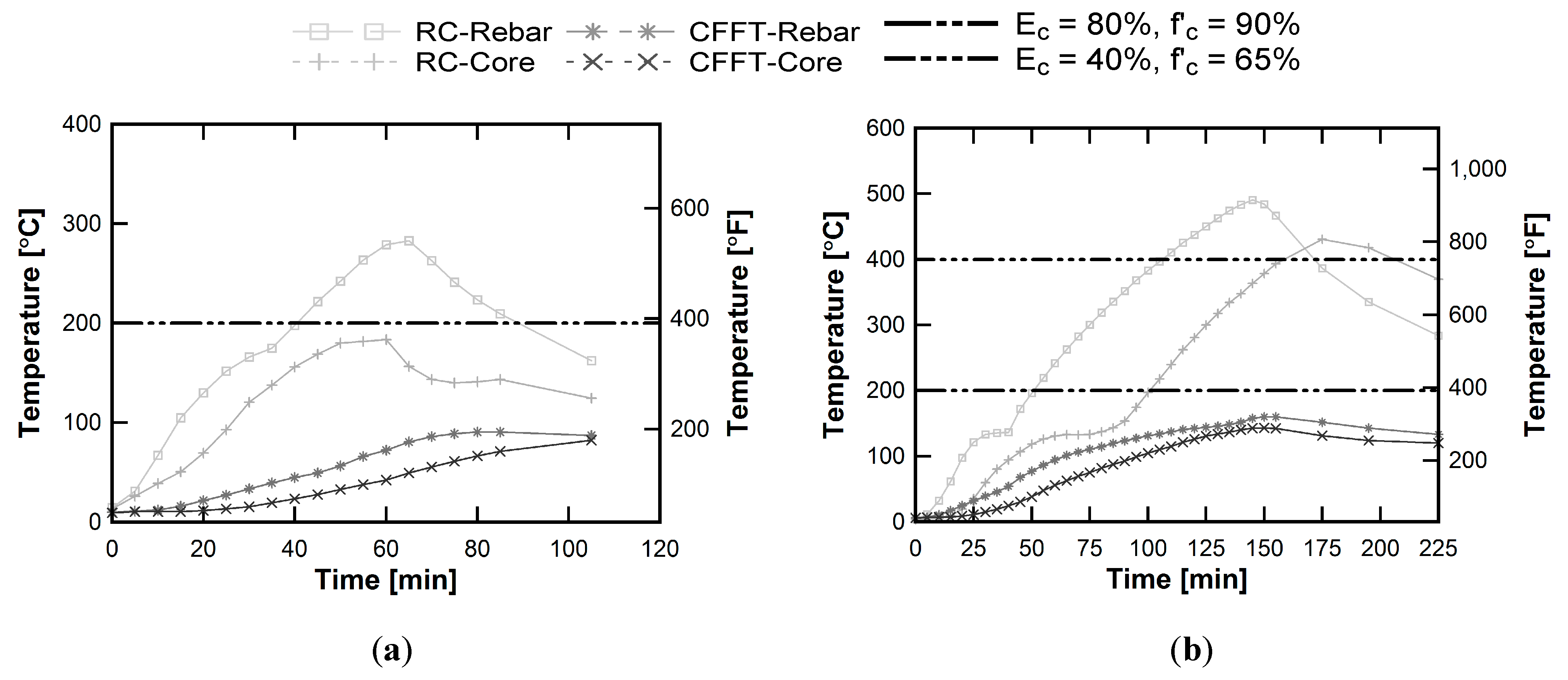
Although the columns showed minimal evidence of structural damage, the temperatures of the interior concrete recorded during testing, shown in Figure 12a,b, indicated that there would be a reduction in both strength and stiffness of the RC columns. Chang et al. [37] established a database of concrete mechanical properties after being heated to temperatures as high as 800 °C. The study showed that concrete compressive strength is reduced by 10% at a temperature of 200 °C and by 35% at 400 °C. Similarly, the elastic modulus of concrete is reduced by 20% at 200 °C and by 60% at 400 °C. During the 1-Hr test, the concrete temperature at the level of the rebar reinforcement of the RC column reached 283 °C, exceeding the 200 °C threshold. During the 2-Hr test, the concrete of the RC column reached 431 °C at the core and 491 °C at the level of the rebar. Both temperatures exceed the 400 °C threshold, indicating significant losses in strength and stiffness of the entire cross section.
Figure 12. Interior concrete temperatures during the (a) 1-Hr and (b) 2-Hr tests.
Polymers 07 00876 g012
In comparison, the maximum concrete temperature recorded at the level of the rebar of the CFFT column during the 1-Hr test was 91 °C. For the longer duration tests, the peak concrete temperature of the CFFT column was 160 °C at the level of the rebar. Because the fire protection system was able to keep concrete temperatures of the CFFT columns below 200 °C during both test durations, no significant losses in strength or stiffness were expected in the following residual axial capacity tests.

3.4. Residual Capacity Tests

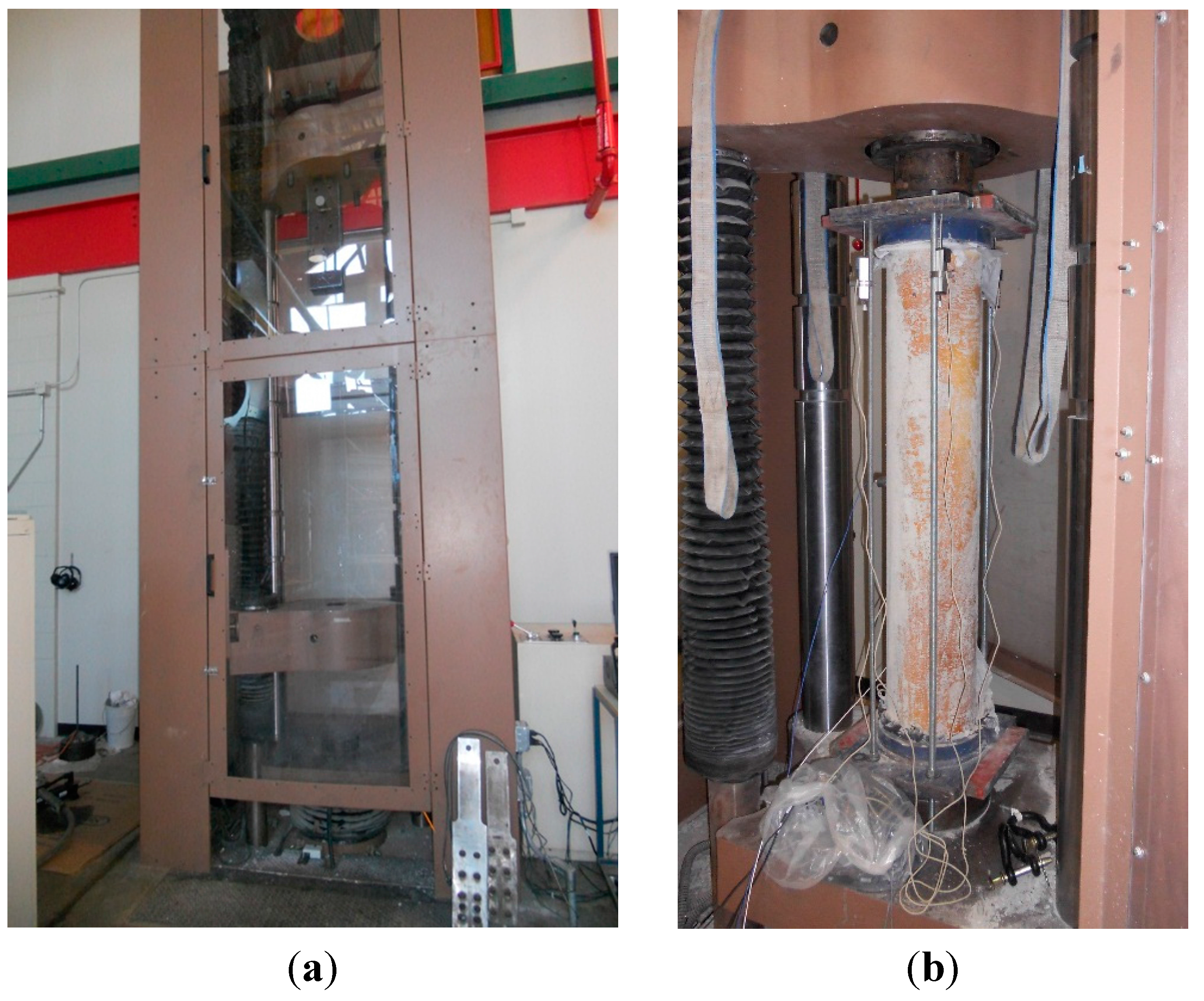
Upon completion of the fire tests, the four damaged columns were returned to the UConn Structures Laboratory for axial capacity testing. Because bridge columns are primarily axial load carrying members, the residual axial load carrying characteristics were chosen as measures of post-fire robustness for the RC and CFFT columns. The four fire damaged columns (RC 1-Hr, RC 2-Hr, CFFT 1-Hr, and CFFT 2-Hr) as well as two undamaged benchmark columns, one of each type, were loaded axially to failure using a 1779 kN (400 kip) Satec load frame controlled by an MTS FlexTest 40 controller. The empty load frame is shown in Figure 13a.
Figure 13. (a) Empty 400 kip load frame; and (b) CFFT 1-Hr axial load test setup.
Polymers 07 00876 g013
Prior to testing, the column specimens were capped using steel plates and a high-strength epoxy to ensure uniform distribution of the axial load on the entire column cross section. To minimize potential P-delta effects, lubricated spherical bearings were used on either end of the column, and measurements were taken to ensure each column was aligned vertically with the load frame. A maximum of eccentricity of 6.35mm (¼ in.) was anticipated which would result in minimal unintended flexural loads.
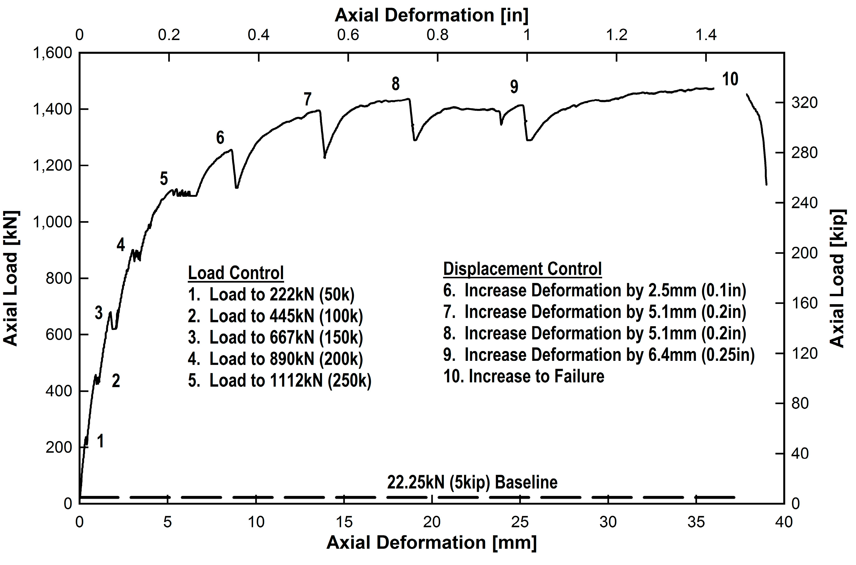
The 10-step loading protocol shown in Figure 14 was used to determine the axial load carry characteristics of the fire damaged and benchmark columns. The load was increased by 222 kN (50 kip) for the first five steps. Starting with step 6, displacement control was used to capture the softening effects of each column. Between each step, the columns were unloaded to a baseline load of 22.25 kN (5 kip) to capture unloading and reloading characteristics. The axial loads were captured directly from the controller, and the axial deformations of the columns were measured using four 50 mm (2 in.) Humboldt potentiometers. Figure 13b shows the complete load frame and potentiometer test setup of the CFFT 1-Hr column.
Figure 14. Loading protocol for axial capacity tests.
Polymers 07 00876 g014

3.5. Residual Axial Strength

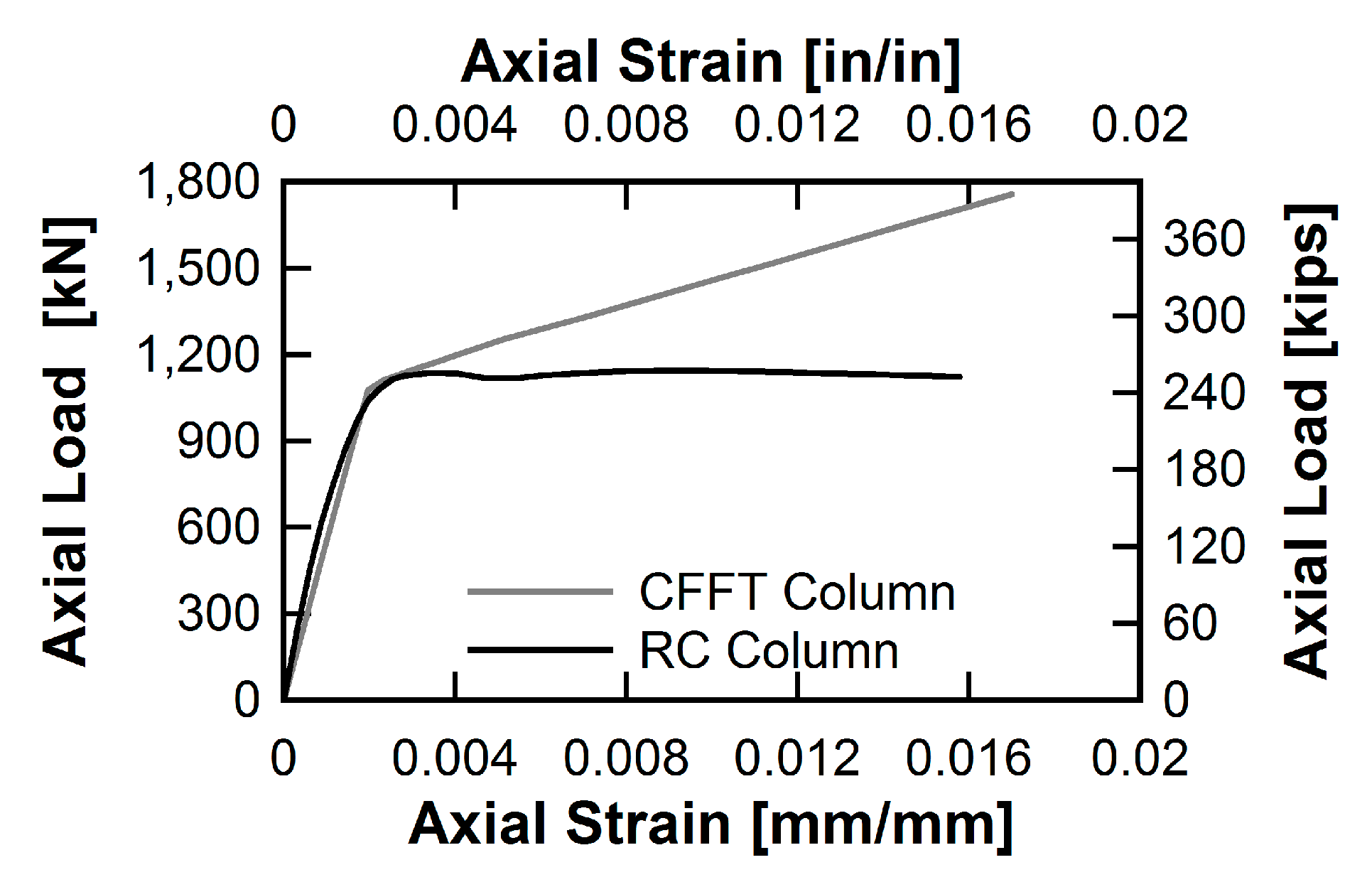
The load-deformation curves obtained from the six axial capacity tests are displayed in Figure 15, and a summary of the results can be found in Table 3. Strength measurements were taken at two locations along the curves. First, the maximum capacity was recorded. Next, the axial capacity at an axial deformation, δP, equal to 10 mm was recorded. This measurement was selected because the RC-Benchmark column first exhibits a loss in strength at δP = 10 mm. The maximum axial capacities of the RC columns were reduced by 3.3% and 23.8% after one and two hours of exposure, respectively. At δP = 10 mm, the residual axial capacities of the RC columns were compromised by 14.1% and 26.7% for the same respective test durations.
In contrast, the CFFT columns showed no significant loss in maximum capacity. The CFFT-1-Hr column had a negligible maximum capacity loss of 2.6%. The CFFT-2-Hr column actually exhibited a 7.3% increase in maximum capacity. The fire protection system applied to the surface of the CFFT columns allowed the concrete temperatures to elevate but not exceed 200 °C. In addition, the FRP tube slowed evaporation of the column’s moisture content creating an environment similar to steam curing and causing a slight increase in maximum capacity. Negligible axial capacity losses of 2.7% and 5.2% were also recorded for the CFFT columns at δP = 10 mm after one and two hours of exposure, respectively.
Figure 15. Load-deformation relationships of RC and CFFT fire damaged columns.
Polymers 07 00876 g015
Table 3. Summary of test capacity results of fire damaged specimens.
Axial Capacity ParameterRC ColumnsCFFT Columns
Benchmark1-Hr Exposure2-Hr ExposureBenchmark1-Hr Exposure2-Hr Exposure
Maximum Capacity, kN (kip)1,094 (246)1,058 (238)834 (187)1,467 (330)1,429 (321)1,574 (354)
Capacity at δP = 10 mm, kN (kip)1,075 (242)909 (204)789 (177)1,276 (287)1,242 (279)1,210 (272)
Axial Ductility4.904.276.4415.911.913.5
Axial Stiffness, kN/mm (kip/in.)423 (2413)246 (1406)142 (808)416 (2377)443 (2529)310 (1772)

3.6. Axial Ductility and Residual Axial Stiffness

Ductility is traditionally defined as the ratio of ultimate displacement over yield displacement. However, the definitions of ultimate displacement and yield displacement are not always easily defined for reinforced concrete structures. In this study, the axial yield displacement is defined as the displacement corresponding to an average axial strain of 0.002, marked by the yield line in Figure 15, and the ultimate displacement is defined as the displacement at which the axial load drops to 85% of the maximum.
The RC columns not only exhibited losses in axial capacity, but also in initial axial stiffness. The initial axial stiffness of each specimen was measured as a secant stiffness between the origin and the point at which the axial strain value is 0.002. After the 1-Hr test, the RC column had lost 41.7% of its initial axial stiffness. For the same duration, the CFFT column did not show any initial axial stiffness loss. For the longer test, the CFFT column did show a 25.5% loss in initial axial stiffness. However, the RC column exhibited a significantly greater loss of 66.5% after the 2-Hr test.
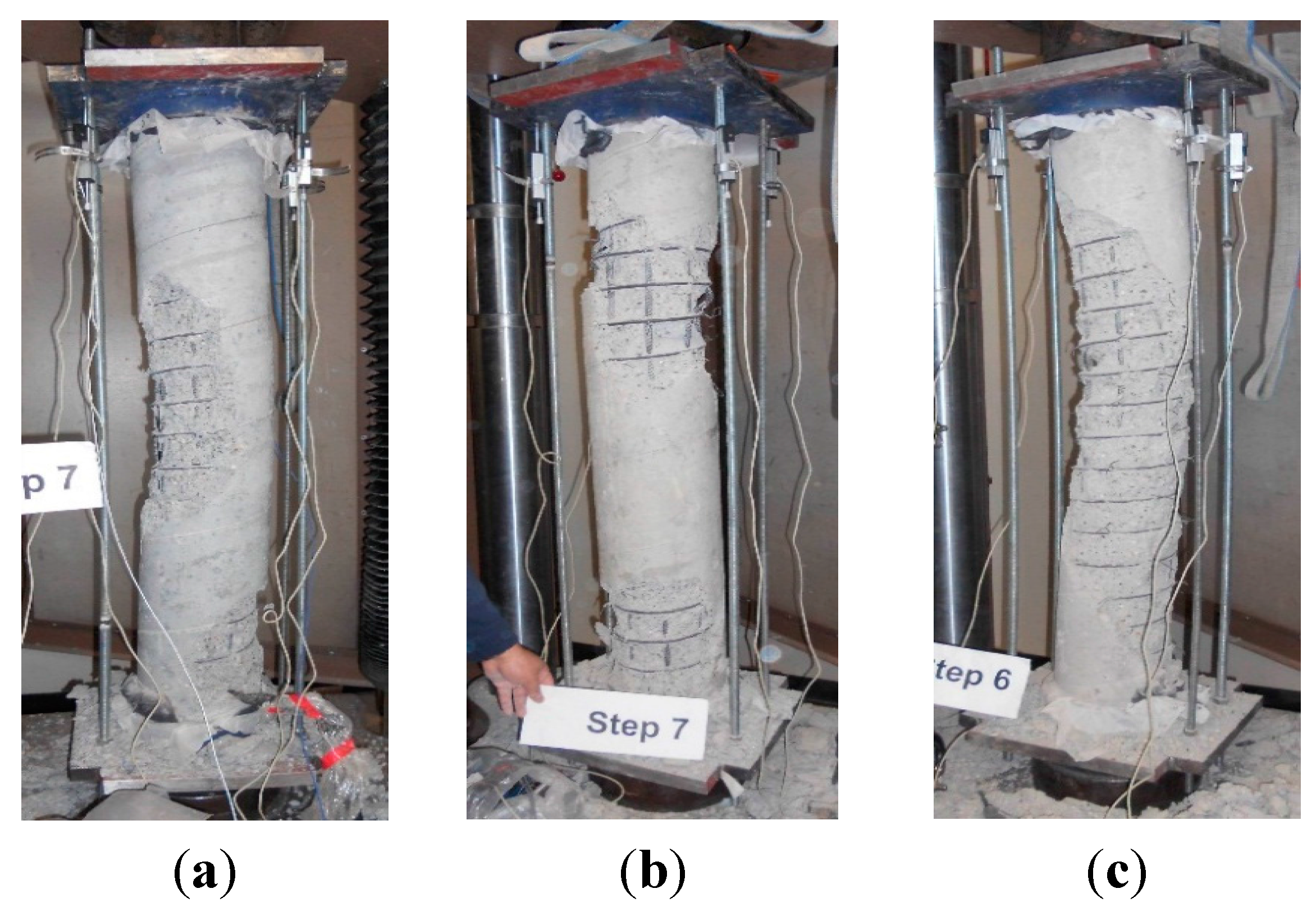
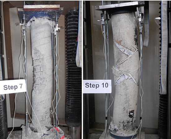
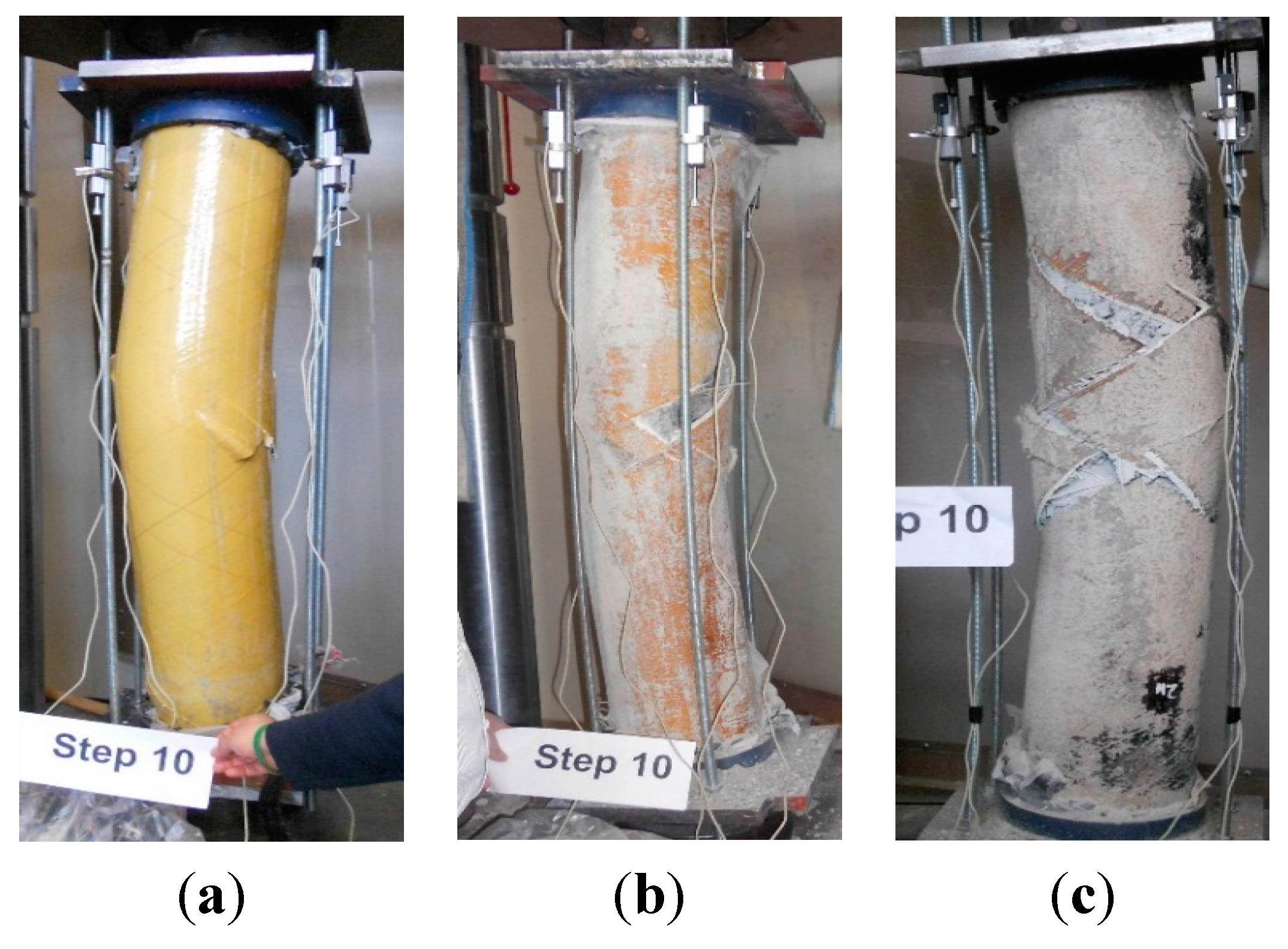
3.7. Failure Modes

Figure 16 displays the failure modes of the RC-benchmark, 1-Hr, and 2-Hr columns under the incremental axial load. The failure mode of the RC-benchmark column was identified as concrete crushing at midspan which is the typical failure mode for a RC column under pure axial compression. The degradation of the compressive strength of the concrete material is seen in the failure mode of the fire-exposed RC columns. The degraded cover material spalled prematurely, ultimately resulting in the reduced axial capacity of the fire-damaged columns. The columns deformed axially until step 6 of the loading protocol when the loss of the cover concrete became non-uniform.
Figure 16. Failure modes of RC-benchmark (a); 1-Hr (b); and 2-Hr (c) exposure columns.
Polymers 07 00876 g016
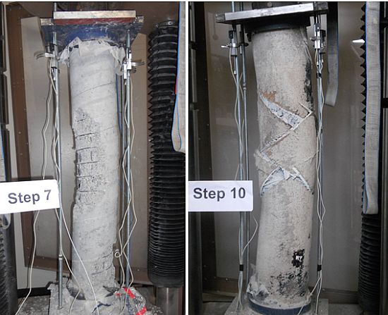
Similar photos of the axial failure modes of the CFFT columns are shown in Figure 17. Because, the fire protection system was able to keep the FRP and concrete temperatures low, the fire-exposed CFFTs exhibit the same failure mode that is seen in the CFFT-benchmark column. Although the photos look as though the columns had significant bending stresses, the cap rotations measured by the potentiometers showed negligible rotation of the steel caps until step 10 when the FRP tubes ruptured at midspan.
Figure 17. Failure modes of CFFT-benchmark (a); 1-Hr (b); and 2-Hr (c) columns.
Polymers 07 00876 g017

4. Conclusions

The following observations and conclusions highlight the findings of this study:
Degradation of the concrete material of RC columns can occur during exposure to extreme temperatures without showing significant outward signs of damage. The most noticeable sign of material degradation after the conducted experiments was a change in the sound properties heard when the RC column surfaces were tapped.
The loss of compressive strength and decrease in elastic modulus of the concrete results in reduced axial capacity and initial axial stiffness of RC bridge columns exposed to fire.
The RC columns exhibited losses of 15.4% and 26.6% in axial capacity and 41.8% and 66.4% in initial axial stiffness after one hour and two hours of exposure to extreme temperature, respectively.
Although the 2-Hr CFFT column exhibited discoloration of the FRP tube, the Tyfo® CFP system provided sufficient fire protection to the CFFT columns allowing them to maintain their axial load carrying capabilities after more than two hours of extreme temperature exposure.
No meaningful loss in axial capacity was observed in the CFFT columns after the 1-Hr or 2-Hr tests. There was also no loss initial axial stiffness after one hour, and just a 25.5% loss in initial axial stiffness after more than two hours of exposure to extreme temperature.
The significant loss of axial strength and stiffness observed in the fire damaged RC columns resulted in larger values of axial ductility when compared to the undamaged column.

Acknowledgment

This material is based upon work supported by the USA Department of Homeland Security under the Department of Homeland Security, Homeland Security Science, Technology, Engineering, and Mathematics (DHS HS–STEM) Career Development Grant Award Number 2008-ST-061-TS002. The views and conclusions contained in this document are those of the authors and should not be interpreted as necessarily representing the official policies, either expressed or implied, of the USA Department of Homeland Security. The authors would like to thank the staff at Guardian Fire Testing Facility for performing the experiments. Special thanks to Matt Smith of National Oilwell Varco for donating the FRP tubes, and Peter Glaude and Serge Doyan for their machining and fabrication work. Also, the assistance provided by Masoud Mehrraoufi and Kevin Zmetra during construction and axial capacity testing is very much appreciated. The authors are very appreciative of Fyfe for the donation of the fire protection system for the fire experiments.

Author Contributions

Alicia Echevarria was a doctoral candidate at the University of Connecticut for the duration of this research. Arash E. Zaghi was Alicia Echevarria’s advisor and the Principal Investigator for this research. Alicia Echevarria developed the experimental program with the guidance of Arash E. Zaghi. Alicia Echevarria also processed the data and drafted this manuscript. Richard Christenson served as technical advisor for this research and assisted with the axial capacity tests and data processing. Rachel Plank performed background research on the performance of FRP materials in extreme temperatures which was incorporated into the literature review portions of this manuscript. Rachel Plank also travelled to Buffalo, NY to assist with the experimental fire tests.

Conflicts of Interest

The authors declare no conflict of interest.

References

  1. Lee, G.C.; Mohan, S.B.; Huang, C.; Fard, B.N. A Study of U.S. Bridge Failures; Technical Report 13-0008 for the Multidisciplinary Center for Earthquake Engineering (MCEER): Buffalo, NY, USA, 2013. [Google Scholar]
  2. Li, Y.; Ahuja, A.; Padgett, J.E. A review of methods to assess, design for, and mitigate multiple hazards. J. Perform. Constr. Facil. 2012, 26, 104–117. [Google Scholar] [CrossRef]
  3. Kodur, V.; Gu, L.; Garlock, M. Review and assessment of fire hazard in bridges. J. Transp. Res. Board 2010, 2172, 23–29. [Google Scholar] [CrossRef]
  4. National Fire Protection Association (NFPA). Standard for Road Tunnels, Bridges, and other Limited Access Highways; NFPA: Quincy, MA, USA, 2011. [Google Scholar]
  5. Garlock, M.E.M.; Quiel, S.E. Plastic axial load and moment interaction curves for fire-exposed steel sections with thermal gradients. J. Struct. Eng. 2008, 134, 874–880. [Google Scholar] [CrossRef]
  6. Quiel, S.E.; Garlock, M.E.M.; Dwaikat, M.M.S.; Kodur, V.K.R. Predicting the demand and plastic capacity of axially loaded steel beam-columns with thermal gradients. Eng. Struct. 2014, 58, 49–62. [Google Scholar] [CrossRef]
  7. Agarwal, A.; Varma, A.H. Fire induced progressive collapse of steel building structures: The role of interior gravity columns. Eng. Struct. 2014, 58, 129–140. [Google Scholar] [CrossRef]
  8. Han, L.H.; Chen, F.; Liao, F.Y.; Tao, A.; Uy, B. Fire performance of concrete filled stainless steel tubular columns. Eng. Struct. 2013, 56, 165–181. [Google Scholar] [CrossRef]
  9. Kodur, V.K.R.; McGrath, R. Fire endurance of high strength concrete columns. Fire Technol. 2003, 39, 73–87. [Google Scholar] [CrossRef]
  10. Kodur, V.K.R.; Cheng, F.P.; Wang, T.C.; Sultan, M.A. Effect of strength and fiber reinforcement on the fire resistance of high strength concrete columns. J. Struct. Eng. 2003, 129, 253–259. [Google Scholar] [CrossRef]
  11. Kodur, V.K.R.; Phan, L. Critical factors governing the fire performance of high strength concrete systems. Fire Saf. J. 2007, 42, 482–488. [Google Scholar] [CrossRef]
  12. Kodur, V.K.R.; McGrath, R. Effect of silica fume and lateral confinement on fire endurance of high strength concrete columns. Can. J. Civ. Eng. 2006, 33, 93–102. [Google Scholar] [CrossRef]
  13. Green, M.F.; Bisby, L.A.; Fam, A.Z.; Kodur, V.K.R. FRP confined concrete columns: Behaviour under extreme conditions. Cem. Concr. Compos. 2006, 28, 928–937. [Google Scholar] [CrossRef]
  14. Chowdhury, E.U.; Bisby, L.A.; Green, M.F.; Kodur, V.K.R. Investigation of insulated FRP-wrapped reinforced concrete columns in fire. Fire Saf. J. 2007, 42, 452–460. [Google Scholar] [CrossRef]
  15. Cree, D.; Chowdhury, E.U.; Green, M.F.; Bisby, L.A.; Bénichou, N. Performance in fire of FRP-strengthened and insulated reinforced concrete columns. Fire Saf. J. 2012, 54, 86–95. [Google Scholar] [CrossRef]
  16. Gefu, J.; Li, G.; Li, X.; Pang, S.; Jones, R. Experimental study of FRP tube encased concrete cylinders exposed to fire. Compos. Struct. 2008, 85, 149–154. [Google Scholar] [CrossRef]
  17. Bisby, L.A.; Kodur, V.K.R.; Green, M.F. Fire endurance of fiber-reinforced polymer-confined concrete columns. ACI Struct. J. 2005, 102, 883–891. [Google Scholar]
  18. Kodur, V.K.R.; Bisby, L.A.; Green, M.F. Preliminary guidance for the design of FRP-strengthened concrete members exposed to fire. J. Fire Prot. Eng. 2007, 17, 5–26. [Google Scholar] [CrossRef]
  19. Alos-Moya, J.; Paya-Zaforteza, I.; Garlock, M.E.M.; Loma-Ossorio, E.; Schiffner, D.; Hospitaler, A. Analysis of a bridge failure due to fire using computational fluid dynamics and finite element models. Eng. Struct. 2014, 68, 96–110. [Google Scholar] [CrossRef]
  20. Garlock, M.E.M.; Paya-Zaforteza, I.; Kodur, V.K.R.; Gu, L. Fire hazard in bridges: Review, assessment and repair strategies. Eng. Struct. 2012, 35, 89–98. [Google Scholar] [CrossRef]
  21. Echevarria, A.; Zaghi, A.E.; Chiarito, V.; Christenson, R.; Woodson, S. Experimental comparison of the performance and residual capacity of CFFT and RC bridge columns subjected to blasts. J. Bridge Eng. 2015. under review. [Google Scholar]
  22. Echevarria, A. Comparison of the Performance of RC and CFFT Bridge Piers under Multiple Hazards. Doctoral Dissertation, University of Connecticut, Storrs, CT, USA, 15 September 2014. [Google Scholar]
  23. Echevarria, A.; Zaghi, A.E.; Chiarito, V.; Christenson, R. Blast Resilience of Concrete-Filled FRP Tube (CFFT) Bridge Columns. In Proceedings of the 7th International Conference on Bridge Maintenance, Safety and Management, Shanghai, China, 7–11 July 2014.
  24. Kavianipour, F.; Saiidi, M. Shake Table Testing of a Quarter-Scale 4-Span Bridge with Composite Piers. In Proceedings of the 6th International Conference on Bridge Maintenance, Safety and Management, Stresa, Italy, 8–12 July 2012; pp. 1966–1973.
  25. Saiidi, M.; Vosooghi, A.; Cruz, C.; Motaref, S.; Ayoub, C.; Kavianipour, F.; O’Brien, M. Earthquake-resistant bridges of the future with advanced materials. In Performance-Based Seismic Engineering—Vision for an Earthquake Resilient Society; Springer Science and Business Media: Dordrecht, The Netherlands, 2014. [Google Scholar]
  26. Zaghi, A.E.; Saiidi, M.; Mirmiran, A. Shake table response and analysis of a concrete-filled FRP tube bridge column. Compos. Struct. 2012, 94, 1564–1574. [Google Scholar] [CrossRef]
  27. Zhu, Z.; Ahmad, I.; Mirmiran, A. Seismic performance of concrete-filled FRP tube columns for bridge substructure. J. Bridge Eng. 2006, 11, 359–370. [Google Scholar] [CrossRef]
  28. Mirmiran, A.; Shahaway, M. A new concrete-filled hollow FRP composite column. Composites 1996, 27, 263–268. [Google Scholar] [CrossRef]
  29. Modjeski and Masters, Inc. Comprehensive Design Example for Prestressed Concrete (PSC) Girder Superstructure Bridge with Commentary; Federal Highway Administration: Arlington, VA, USA, 2003. [Google Scholar]
  30. American Association of State Highway Transportation Officials (AASHTO). LRFD Bridge Design Specifications, 6th ed.; AASHTO: Washington, DC, USA, 2012. [Google Scholar]
  31. Imbsen Software Systems. XTract; TRC Bridge Design Software: Sacramento, CA, USA, 2007. [Google Scholar]
  32. AASHTO. LRFD Guide Specifications for Design of Concrete-Filled FRP Tubes for Flexural and Axial Members, 1st ed.; AASHTO: Washington, DC, USA, 2012. [Google Scholar]
  33. NOV Fiberglass Systems. Red Thread II Piping Systems. National Oilwell Varco: San Antonio, TX, USA, 2009. Available online: http://www.corrosionfluid.com/assets/pdf/smith-fibercast-red-thread-2-ii-fiberglass-pipe-piping-brochure.pdf (accessed on 22 January 2012).
  34. Saiidi, M.; Sureshkumar, K.; Pulido, C. A simple model for confined concrete. J. Struct. Eng. 2005, 9, 101–104. [Google Scholar]
  35. Omega. High Temperature Inconel Overbraided Ceramic Fiber Insulated Thermocouples; Omega Engineering, Inc.: Stamford, CT, USA, 2013. [Google Scholar]
  36. Fyfe. Tyfo® CFP System; Fyfe, Co., Limited Liability Corporation: San Diego, CA, USA, 2013. [Google Scholar]
  37. Chang, Y.F.; Chen, Y.H.; Sheu, M.S.; Yao, G.C. Residual stress-strain relationship for concrete after exposure to high temperatures. Cem. Concr. Res. 2006, 36, 1999–2005. [Google Scholar] [CrossRef]

