1. Introduction
The application of fiber reinforced polymer (FRP) materials used in strengthening and stabilizing historic, mainly masonry, structures is associated with many advantages, such as their low weight, high effectiveness, limited interventions into and damage to historic structures and potential reversibility [
1]. Until the end of the 1990s, restoring historic masonry vaults was performed by traditional methods. Depending on the scale and magnitude of the vault’s damage, simple stabilization (stiffening) of supports by means of so-called vault ties, the activation of tendons, application of concrete shells 80 to 120 mm thick or direct suspension of damaged vaults on partial steel ties was usually performed. In the last 20 years, innovative strengthening techniques based on the use of polymeric and, more recently, cementitious fiber reinforced composite materials (carbon, glass, aramid,
etc.) have been adopted for the stabilization and strengthening of masonry vaults applied, as a rule, on the masonry surface of the vaulted structures.
The issues of strengthening masonry structures with composites based on high-strength fibers and epoxy resin are addressed by numerous workplaces and universities. The application of FRP materials in the restoration of historic and listed buildings to-date has been focused primarily on the stabilization of vertical load-bearing and vaulted structures to withstand the effects of horizontal loads imposed by technical and natural seismicity [
2,
3,
4,
5].
Currently, the main areas of experimental and theoretical research of masonry vault reinforcement using FRP materials are particularly the determination of their optimal placement, for example strengthening applied at the extrados provides a higher deformation capacity prior to failure endowing arches with considerable ductility behavior, while strengthening at the intrados is the most effective option to increase strength [
6]. The positioning of numerous reinforcing elements [
7,
8,
9,
10,
11], the verification of the failure mechanism of reinforced vaults [
12,
13], verification of innovative shapes of reinforcement (for example “Ω” shaped reinforcement [
14]), the use of combinations of new materials (carbon fiber reinforced cementitious matrix (C-FRCM) [
15], poliparafenilenbenzobisoxazole fiber reinforced cementitious matrix (PBO-FRCM) [
16], basalt textile-reinforced mortar (BTRM) [
17] and others) are other elements considered.
Dynamic response is currently very often used to identify potential damage to structures that may not be otherwise detectable. Assuming a low level of dynamic (
i.e., non-destructive) excitation, the principle of such tests is the comparison of dynamic characteristics of the structure [
18,
19]. The characteristics most frequently in mind are the resonant frequencies and their corresponding modes of vibration. A change in frequency, most often a frequency drop, may signal the appearance of inner cracks in the tested specimen. A change in the mode of vibration, in turn, indicates its global failure. Numerical modeling of the behavior of masonry vaults under dynamic loads [
20,
21,
22,
23] and the possibility of its utilization for integrity assessment of masonry vaults are also included.
Theoretical research is focused primarily on the analytical and numerical modeling of the stability behavior of masonry vaults and their failure mechanism [
24,
25,
26,
27], stress state analysis of reinforced vaults [
28,
29,
30], limit load analysis of masonry vaults [
31,
32,
33,
34,
35,
36] and also on detailed masonry vault analysis taking into account the interaction between bricks and mortar [
37].
Another specific issue is how to reliably encompass the tensile stresses transferred by reinforcing composites applied on the surface of masonry structures in anchoring areas and their distribution through masonry to avoid its secondary damage [
38,
39,
40].
A serious issue encountered in the application of CFRP materials is fire safety of structures reinforced or stabilized with FRP materials. The key element is the critical temperature of the epoxy resin that ranges from 55 to 120 °C [
41]. These temperatures are extremely low in terms of fire safety and are usually reached in the first few minutes of fire. Commonly used elements of structure’s fire protection (especially fire protection cladding) in terms of their usage in historic buildings are very problematic and may limit the use of FRP materials for load bearing structures’ reinforcement.
2. Damaged Vaults over the Arcaded Walk on 1st Aboveground Story of the Monastery Convent
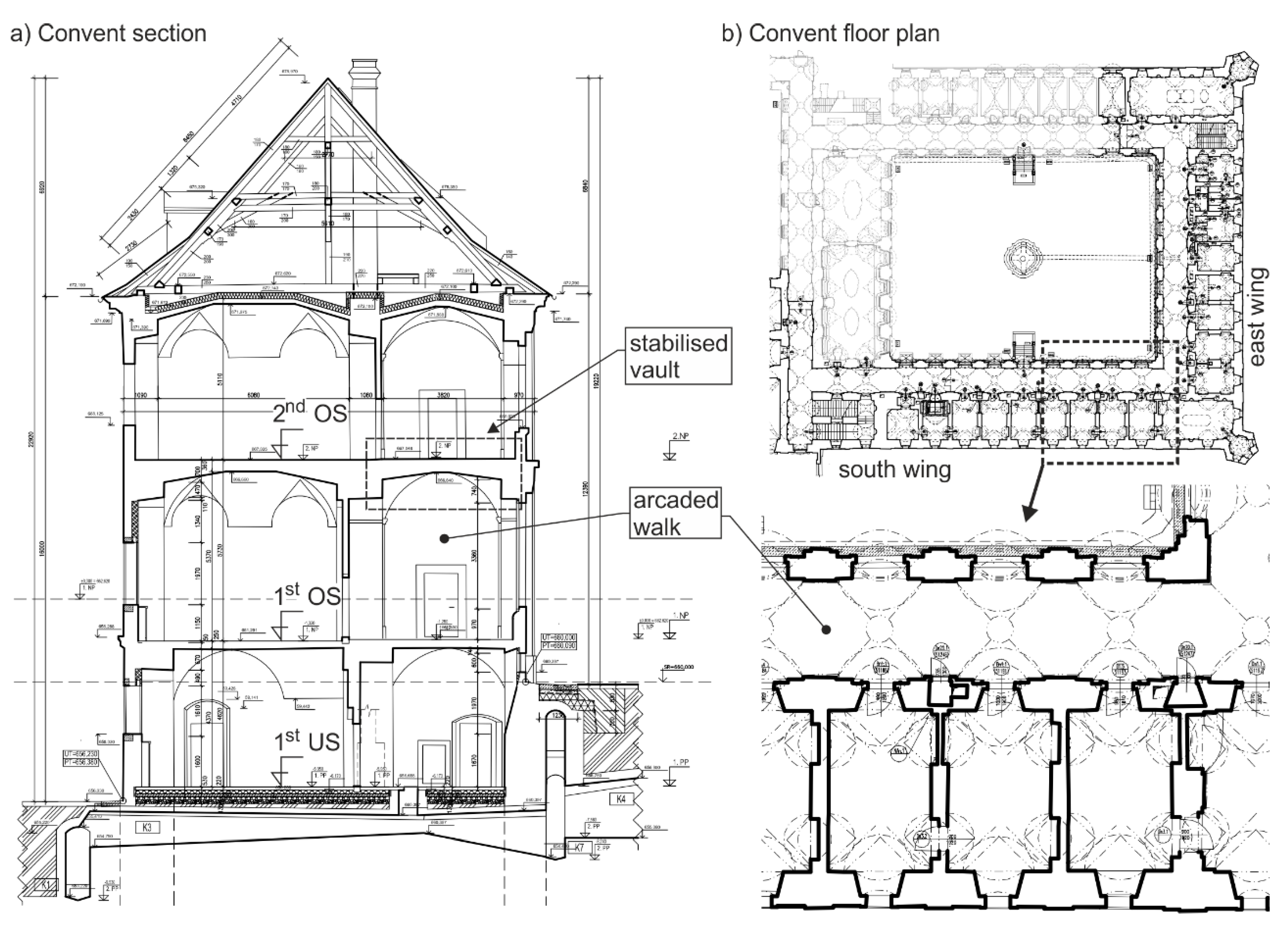
The convent, which is part of an extensive monastery complex, is largely a two-tract building with one underground, two aboveground stories and a timber roof truss (
Figure 1a). The bearing walls of mixed stone masonry (mixture of trachyte, limestone and marlstone) laid out in the longitudinal direction of the building (
Figure 1b)
ca. 1 to 1.5 m thick are founded on masonry strip foundations with the assumed footing bottom depth down to the bedrock. Research did not reveal any mechanical failures of the masonry, which would manifest changes in the footing bottom’s shape. Individual stories are mostly roofed by vault structures of brick masonry (
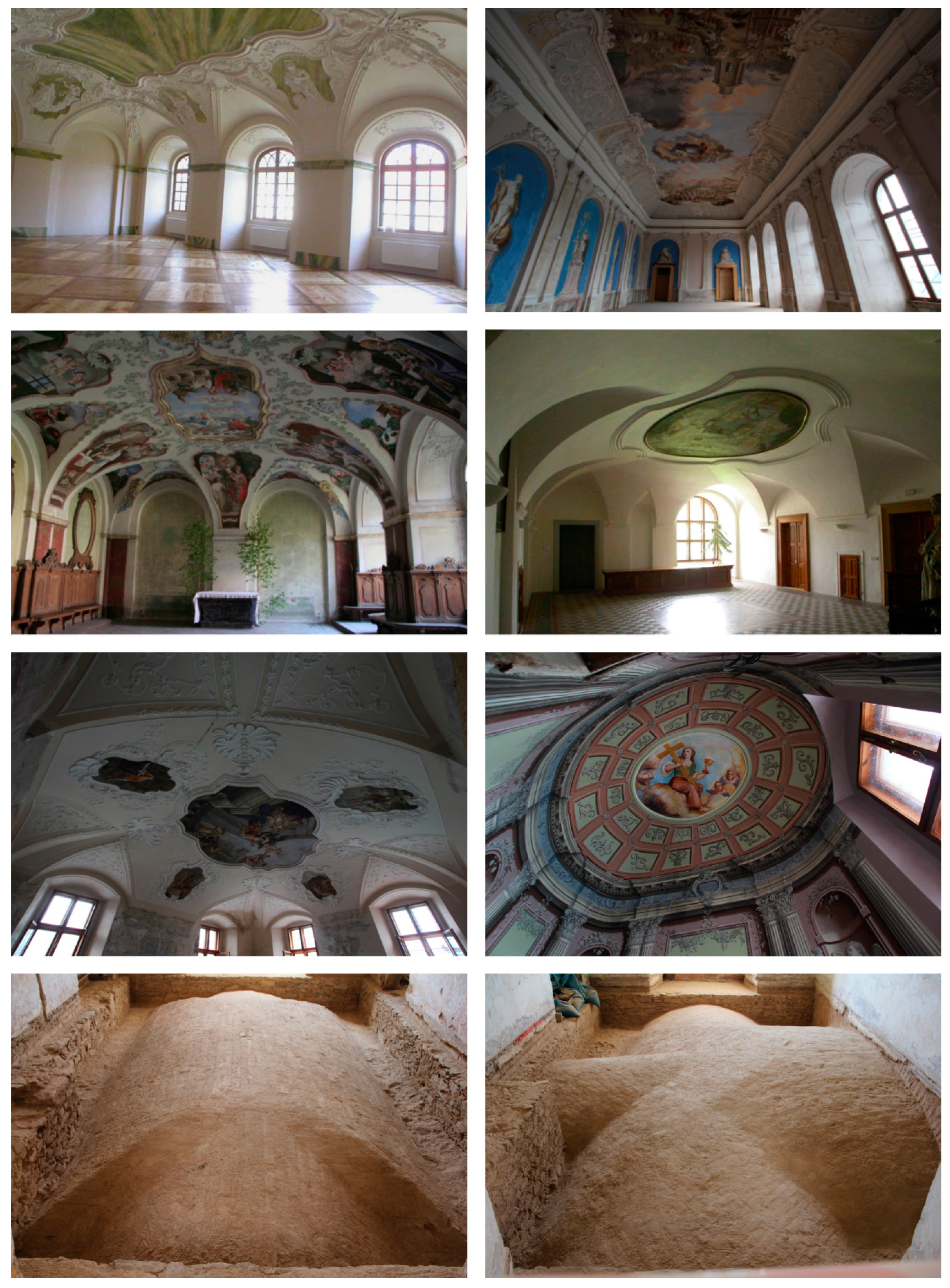
Figure 2).
The Premonstrate Monastery at Teplá near Mariánské lázně (Marienbad, Western Bohemia, Czech Republic) dates back to the second half of the 12th century. Its history is marked by an unprecedented continuity. Up to the second half of the 17th century, the early baroque monastery remained a combination of a substantial part of a mediaeval convent, including, most likely, the preserved arcaded walk, the abbey house, the palace, and the refectory, plus newly built wings of the south and east dormitory added in the 17th century.
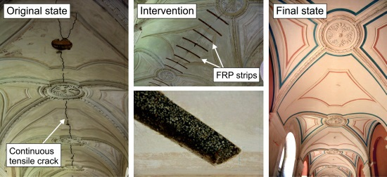
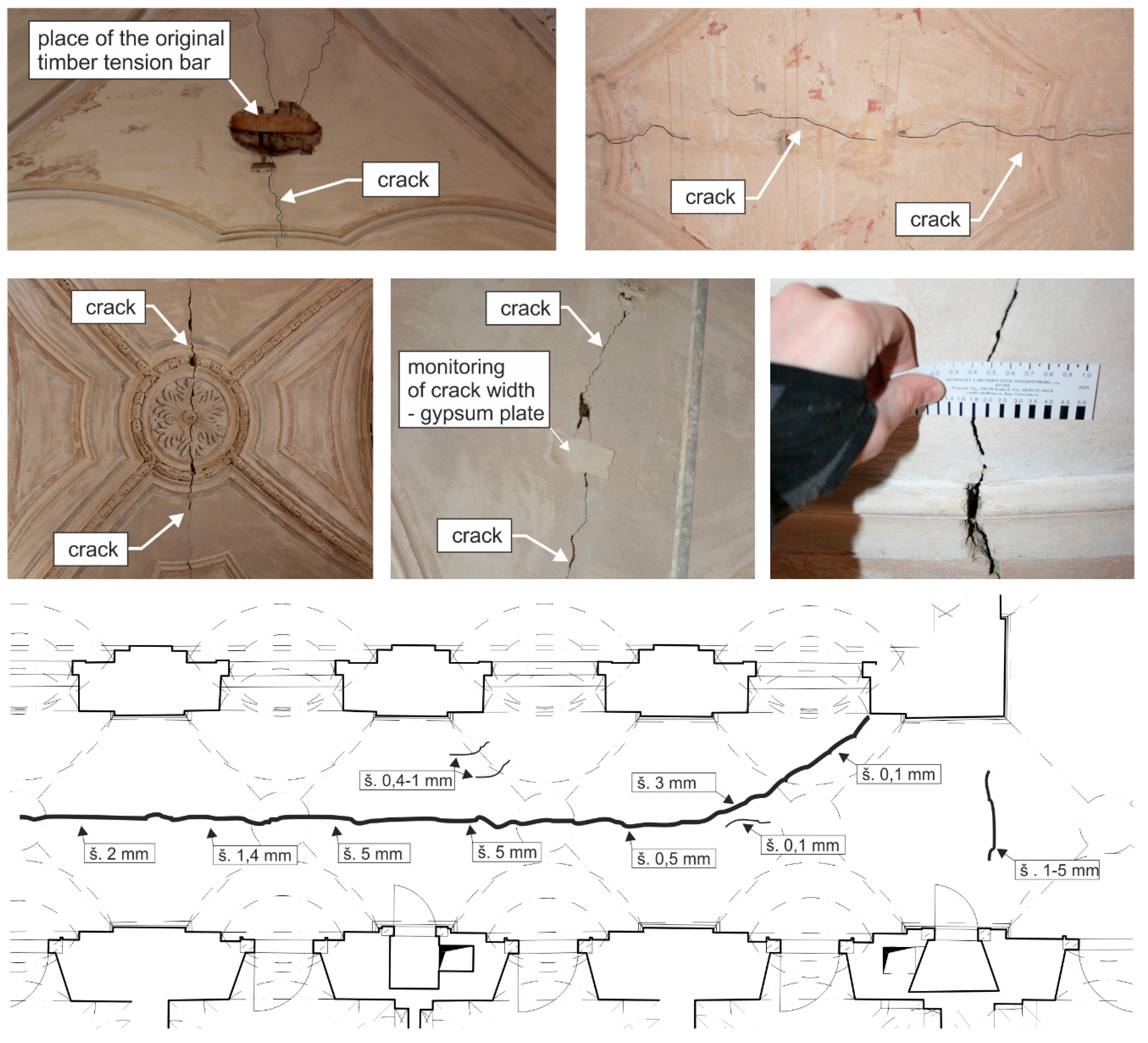
The vaults over the arcaded walk of the south wing of the 1st aboveground story (OS) of the convent, decorated by stucco and plastic reliefs, had been damaged by a prominent, continuous tensile crack at the crown reaching a width of 5 to 40 mm in some vault bays after the removal of plaster (some parts of the crack in plaster have probably been previously repaired) and by minor tensile cracks located mainly in the place where the vaults of the south and east wing crossed (
Figure 3). Similarly, the vaults over the arcaded walk of the east wing of the convent’s 1st OS had been damaged by prominent tensile cracks at the crown. Compared to the cracks in the south wing of the convent, originating most likely due to the wing’s orientation and lower temperature gradient, these cracks were smaller in width. This could also have been, to some extent, caused by a more effective system of tendons in this part of the convent. The type of cracks—mostly unimpaired crack outlines (contours)—testifies to the fact that they were tensile, not shear cracks by origin, which are characterized by outlines impaired due to displacements in the crack. No crushing or crinkling of the surfacing layers in the vault springing area is evident in the vault masonry soffit that could support the existence of tensile cracks in these areas at the vault extrados, in so-called critical parts of the barrel vaults with a central angle greater than 120°, caused by the settlement or angular rotation in the footing bottom,
etc.
Figure 1.
(a) Schematic section of the convent and (b) schematic layout plan of 1st aboveground story (OS) of the convent and detail of the floor plan.
Figure 1.
(a) Schematic section of the convent and (b) schematic layout plan of 1st aboveground story (OS) of the convent and detail of the floor plan.
The vaults used in buildings are statically indeterminate structures characterized by their high sensitivity to deformations, displacements of supports and loading patterns. The barrel vault failure process is characterized by a phase where the vault becomes a statically determinate structure with usually two to four hinges. At this phase, local failure of the area around the cross-sections in which imperfect line hinges are created gradually occurs. The vault failure process as a rule includes two prominent mechanisms—local as well as overall changes in the vault system’s shape (stability criterion) and the vault masonry disintegration due to the effect of tensile and compressive normal stresses exceeding gradually the load-bearing capacity of the vault cross-sections in which hinges have been created (load-bearing capacity criterion).
The total failure—vault collapse—is usually the result of these two mutually interrelated parallel processes. They are both simultaneous and cannot be separated from each other. The stress state and the thrust line pattern under a growing load and a gradual vault failure accurately describe the appearance and development of tensile areas in individual phases of the vault system’s action. Vault collapse in these cases occurs after exceeding the mechanical resistance of partially withstanding cross-sections in the area of created hinges, or by vault stability failure without reaching the ultimate load of the vault cross-section in compression.
Vault failure resulting from loss of stability caused by shape or geometric deflections occurs under loads in which the ultimate bearing capacity of the vault cross-section in compression is not utilized. Insufficient stiffness in relation to horizontal displacement causes a significant decrease in vault load-bearing capacity and vault failure.
Vault structures situated in the arcaded walk on the 1st OS of the convent’s south and east wing are composed of segmented brickwork barrel vaults with lunettes 150 mm thick, with a span of 3.74 and 1.45 m in height. The vault is walled of classic solid burnt bricks onto lime mortar in an “ordinary” way. Over the vault, there is a floor structure with a total thickness at the vault’s crown of 0.35 m consisting of infill material and paving laid in a mortar bed. The loose infill is made up of construction debris (partially naturally compacted during the execution of the above story floor structures) with a large proportion of finer fractions (brick chippings, mixture of sand and mortar residues). The thickness of mixed masonry walls at vault springings is ca. 1.0 and 1.2 m.
Figure 2.
Vault structures with ceiling paintings in the Premonstrate Monastery at Teplá.
Figure 2.
Vault structures with ceiling paintings in the Premonstrate Monastery at Teplá.
Figure 3.
Damaged vaults over the convent’s east wing arcaded walk on 1st OS and the crack width measurements in the southeast corner of the convent.
Figure 3.
Damaged vaults over the convent’s east wing arcaded walk on 1st OS and the crack width measurements in the southeast corner of the convent.
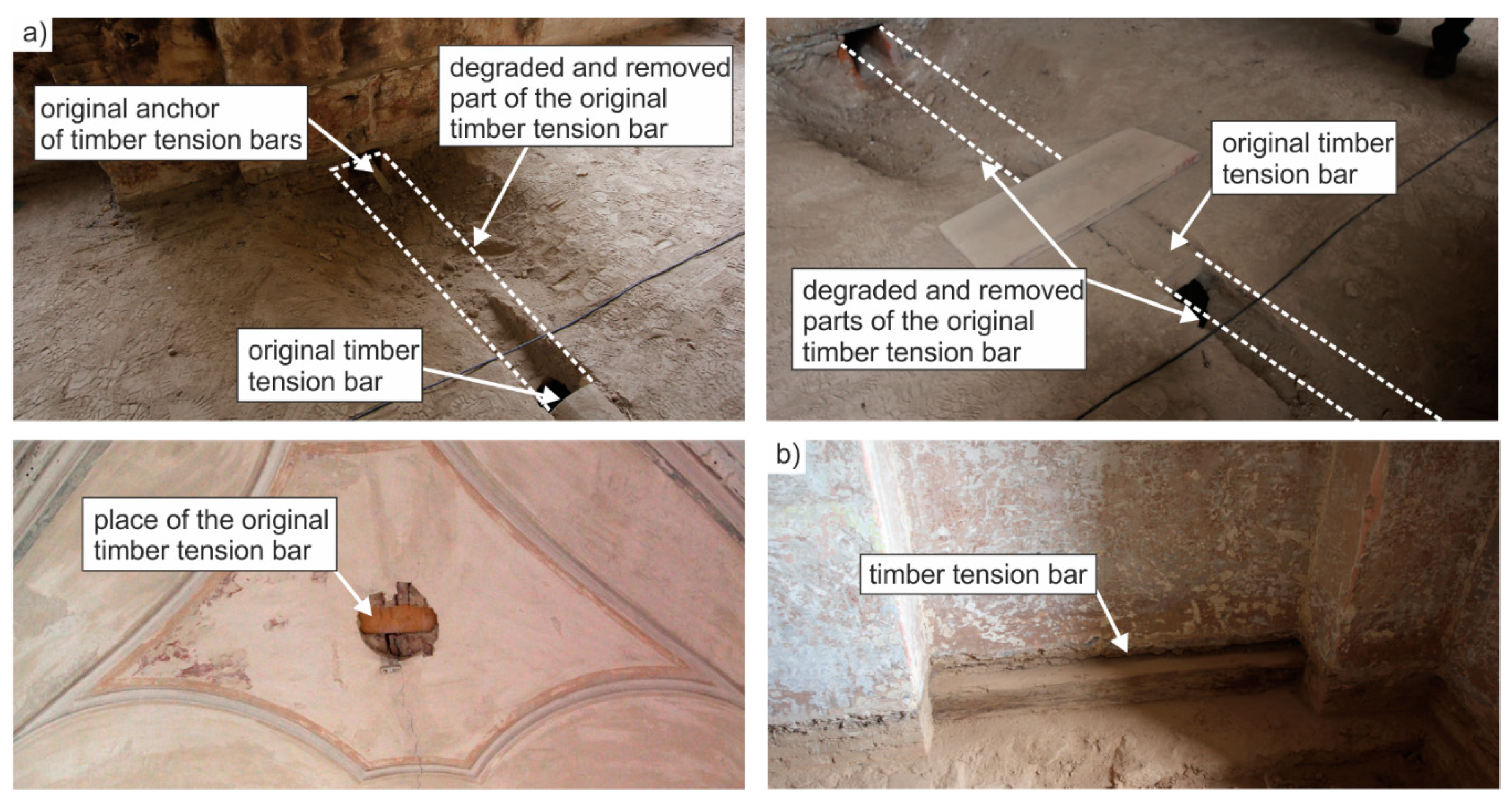
During the last reconstruction of the convent’s 2nd OS in 2004–2008, the original historical system of embedded timber vault tendons at the level of vaults over the 1st OS was replaced with a system of embedded steel tendons Ø 18 mm anchored to perimeter masonry. The effectiveness of these steel tendons could not be verified as they were embedded in the already reconstructed floor structures on the fully operated 2nd OS. For this reason, numerical analysis was made both for the case of effective tendons and the case of ineffective tendons in the 2nd OS floor structure. As will be pointed out below, the vault damage by a tensile crack at the vault crown corresponds to the case of ineffective tendons in the 2nd OS floor structure. This fact was also considered in the reinforcement design of damaged vaults.
Open lunettes are, according to information available, walled on the barrel vault and do not interlock with the masonry of the supports (interior and perimeter wall).
3. Numerical Analysis of Likely Causes of Vault Damage over the Arcaded Walk on 1st OS
The position of the open tensile crack—at the crown of the vault soffit—corresponds to the characteristic damage of barrel vaults caused by tensile stresses at the vault’s crown due to the vertical loading effect, or the characteristic damage of barrel vaults caused particularly by horizontal deformations (displacement) of supports for the case of insufficiently effective vault beam ties—embedded tendons (the compressive thrust line deviates from the core of the vault’s cross-section and adheres to the crown).
In the case of both of the above-mentioned potential causes of vault damage at the crown by a tensile crack in the vault soffit, the reliable function and effectiveness of tendons is of key importance. Despite the massiveness of the masonry structure with a prevailing layout of the principal load-bearing walls in the longitudinal direction of the convent’s south and east wing, interconnected in several places by transversally oriented walls (see
Figure 1b), it is necessary to complement this system of load-bearing walls with efficient tendons—wall and vault ties—to significantly limit the horizontal displacement of vault supports.
The insufficiently effective (prestressed) steel tendons of vaults in the 2nd OS floor structure embedded at vault crowns and in the already reconstructed floor structure (
Figure 4) could not secure this function with due reliability and, therefore, it had to be assumed that the insufficient effectiveness of the steel tendons in the 2nd OS floor structure had been one of the principal causes of the appearance and development of a continuous tensile crack at the vault crown.
Figure 4.
(a) Degraded original historical timber vault tendons (tension bars) on the 1st OS. (b) Original historical timber wall tendons (wall ties) on the 1st OS.
Figure 4.
(a) Degraded original historical timber vault tendons (tension bars) on the 1st OS. (b) Original historical timber wall tendons (wall ties) on the 1st OS.
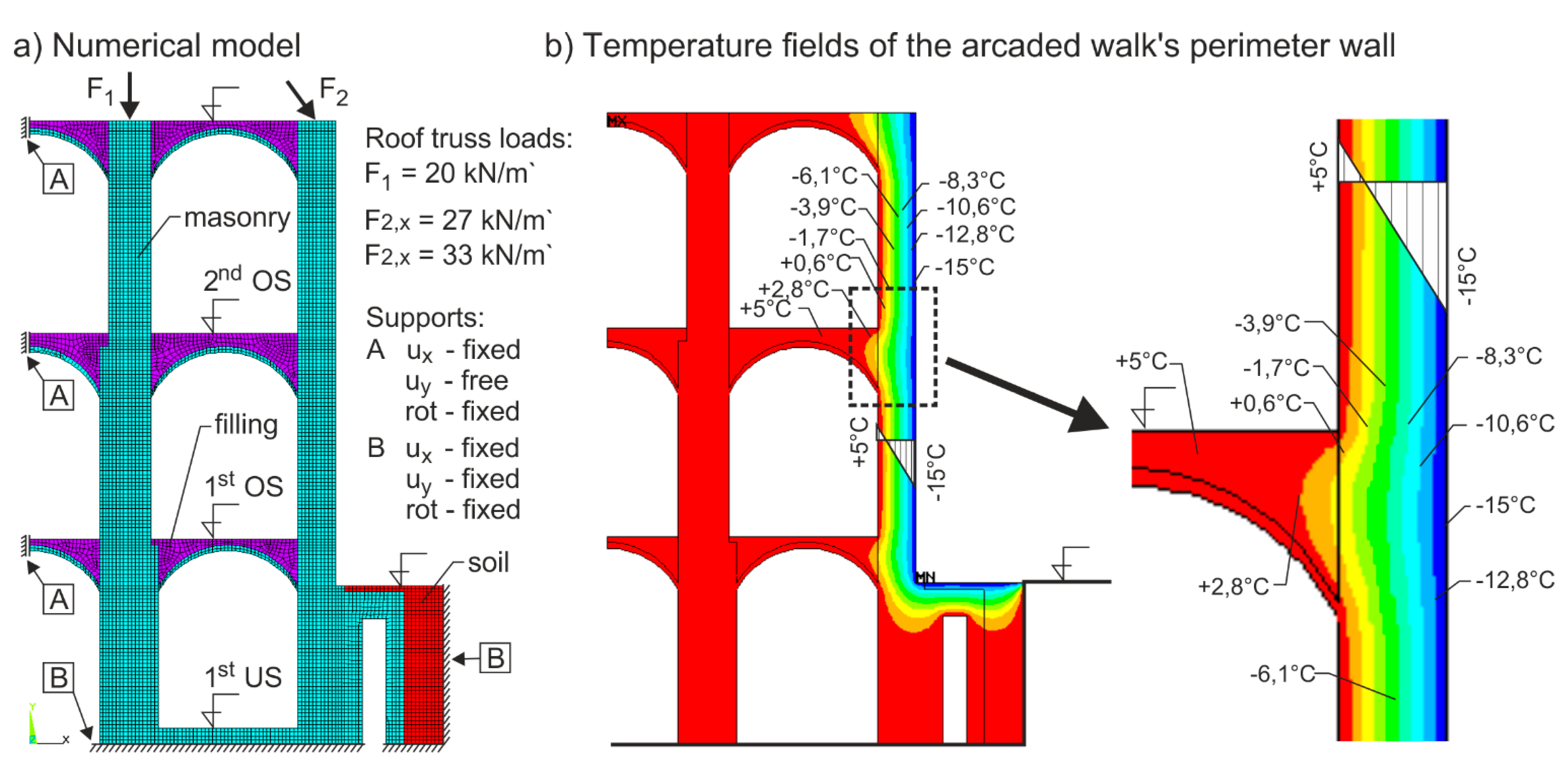
The linear FEM numerical analysis of the stress state of the vaults prior to their damage served to identify the stress state and deformations of the vault system over the arcaded walk on the 1st OS plus the distribution of temperature fields in the masonry walls and vaults in the winter season (
Figure 5b).
The finite model was prepared using the ANSYS software package. The 2D (in-plane) isoparametric four-node finite elements were used (the PLANE42 for a linear static analysis and the PLANE55 for the thermal analysis). The temperature fields, obtained form the thermal analysis, were used as a load for the static analysis (the transfer of loads was conducted with use of build-in ANSYS functions). Several configurations of models have been studied, the number of nodes was 8260 and the number of elements was 7743. A steady-state thermal analysis was conducted. The boundary conditions were defined as prescribed temperatures: +5 °C on internal surfaces and −15 °C on exposed external surfaces (an unheated building/conservative approach/in the winter season). Several groups of loads were applied for the static analysis: thermal loads, the weight of structure and the effects of rest of the structure which included reactions from roof structure. The weight was defined by the density and the gravitational acceleration (10 m/s
2), and the effects of reactions from the roof structure had form of individual forces F1 and F2 (
Figure 5a).
Figure 5.
(a) Numerical model and (b) Finite element method (FEM) analysis of temperature fields of the arcaded walk’s perimeter wall. Force F2, representing the roof truss action, has a horizontal component as the functional capacity of the connection between the tie beam and masonry could not be verified, i.e., potential displacement in the “masonry–tie beam” was considered, which more likely corresponds to the actual state of the historic roof truss.
The calculation was made for a segment of the load-bearing system, including both longitudinal walls on three floors and vaulted structures on all floors. The design load was determined based on the real structure. Due to the requirement for identifying the maximum values to which the structure may be exposed, loosened (ineffective) tendons were considered at all three levels. The calculation did not include changes in the footing bottom’s shape. The calculation identified internal forces in both the vault structure and the system of supports. A homogenized masonry model was used for the calculation, while the modulus of elasticity values and other physical and mechanical characteristics were identified on the basis of mechanical tests of materials sampled from boreholes and based on applicable standards (
Table 1).
Table 1.
Material properties used for numerical analysis. The mechanical characteristics were experimentally obtained (in-situ non-destructive testing and destructive testing in laboratory) where possible (accessible parts of the structure—wall and vault masonry), or derived (for inaccessible parts of the structure—soil and filling material) from the current national standards (ČSN ISO 13822, ČSN EN 1996-1-1 and ČSN EN 1997-1).
| Material | Parameter | Value | Units |
|---|
| Masonry Walls (trachyte) Vaults (bricks) | Young modulus (E)—walls/vaults | 27/4.5 | GPa |
| Poisson ratio | 0.2 | - |
| Density—walls/vaults | 2,100/1,700 | kg/m3 |
| Thermal expansion coefficient | 0.000008 | - |
| Thermal conductivity | 1.5/2.2 | W/(m·K) |
| Filling (construction debris) | Young modulus (E) | 3 | GPa |
| Poisson ratio | 0.2–0.4 | - |
| Density | 1,500 | kg/m3 |
| Thermal expansion coefficient | 0.000008 | - |
| Thermal conductivity | 1.5 | W/(m·K) |
| Soil | Young modulus (E) | 10 | GPa |
| Poisson ratio | 0.2 | - |
| Density | 1,000 | kg/m3 |
| Thermal expansion coefficient | 0.000008 | - |
| Thermal conductivity | 1 | W/(m·K) |
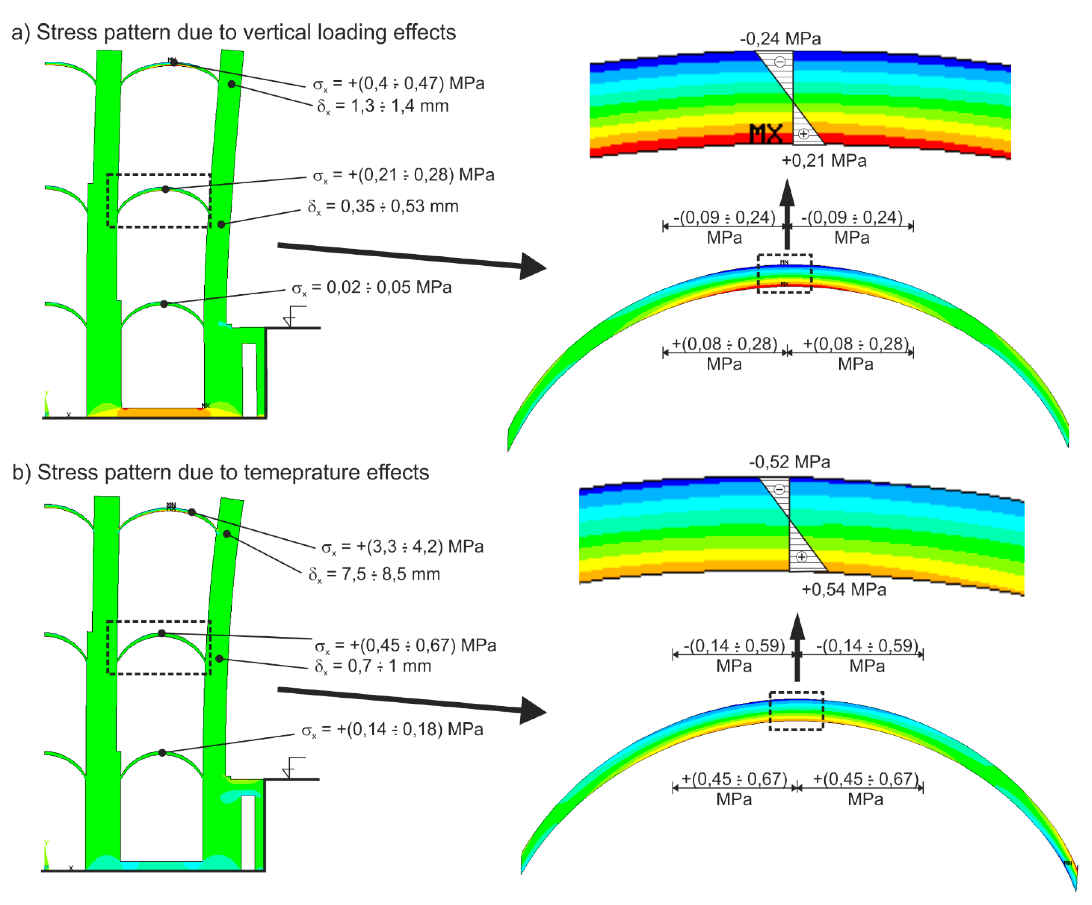
The analysis of the vertical loading effect on the vaults (vault structure’s own weight, weight of the infill and the floor structure), transferred by masonry vaults, assuming statically ineffective historical timber vault tendons degraded by rot, manifested the appearance of tensile stresses +σ
x in the vault’s crown area over the 1st OS with magnitudes from +0.21 to +0.28 MPa (
Figure 6a),
i.e., values exceeding the vault masonry tensile strength. In the case of a failure in the binder, the masonry tensile strength reaches values of
ca. 0.02 MPa (ČSN EN 1996-1-1). Consequently, we may rightly assume that the tensile stresses due to the vertical loading effect may be the cause of the appearance of a tensile crack in the bed joint at the masonry vault’s crown. The analysis of the vertical loading effect transferred by masonry vaults also manifested a potential horizontal displacement of the perimeter wall in the case of insufficiently effective tendons amounting to 0.35–0.53 mm at the vault springing’s level (
Figure 6a).
Figure 6.
(a) Stress-state analysis of the vault structure due to vertical loading effects; (b) Stress-state analysis of the vault structure due to temperature effects.
Figure 6.
(a) Stress-state analysis of the vault structure due to vertical loading effects; (b) Stress-state analysis of the vault structure due to temperature effects.
The numerical analysis of identically vertically loaded vaults with statically effective vault tendons (ties) did not demonstrate the formation of tensile stresses in the vault masonry.
Another potential cause investigated was the effect of the temperature gradient in the perimeter wall in the winter season,
i.e., at an inside temperature of the corridor track of +5 °C and an outside temperature of −15 °C. This effect, as well, results in horizontal deformations (displacement) of the support at the vault springing’s level over the 1st OS ranging from 0.7 to 1 mm (under the perimeter wall’s loading by a temperature gradient of +5 to –15 °C) and the appearance of relatively high tensile stresses in the vault structures amounting from +0.4 to +0.65 MPa (
Figure 6b).
Numerical analyses of vaulted structures made at the authors’ workplace within [
1] revealed the high sensitivity of vaults to the deformations of their supporting structure [
42,
43]. The likely cause of the appearance of tensile stresses in corresponding parts of the vaults and their successive failure by tensile cracks, preceding the appearance of imperfect hinges, may be the horizontal displacement (deformation) of the supports in the order of lower values (mm). For this reason, the deformations of the vault’s supporting structure induced by temperature or seismic (dynamic) effects could be extremely severe.
The non-force temperature effect is characterized by its repetition with each change in temperature—a low-cycle effect causing the so-called “incremental collapse” by reaching the ultimate deformation of e.g., the vault masonry—without reaching the ultimate strength values in the masonry. Individual loading cycles are accompanied by a gradual growth of permanent deformations of the vault structure. If these gradually added permanent deformations reach values of the ultimate tensile deformation of the masonry, a crack appears. After each subsequent loading cycle, the cracks keep growing and developing, although this growth and development is gradually smaller and smaller. The time period necessary for crack appearance and failure, i.e., the number of temperature cycles until failure, depends on the range of elasto-plastic deformations of the vault masonry (ductility).
The performed analysis manifested the occurrence of relatively high values of tensile stresses +σx at the vaults’ crown in the parts of the vault’s cross section adjoining the vault soffit arising due to vertical loading and temperature effects. Both effects, i.e., the vertical loading and the temperature effect, produce tensile stresses at the vault’s crown exceeding the ultimate masonry strength in tension (ČSN EN 1996-1-1), and may be the cause of the appearance of tensile cracks.
Based on the above analysis of the current state of repair, the layout and degradation of vaults over the convent’s arcaded walk on the 1st OS and its securing with a system of tendons, the most likely causes of the mechanical failures of the arcaded walk’s vaults are the vertical loading effect on the vaults and the effect of repetitive (cyclic) deformations of the supporting system, particularly the perimeter corridor wall due to volume changes in perimeter masonry and the non-uniform distribution of temperature fields along the perimeter wall, together with the insufficiently effective securing of vaults by beam ties.
While analyzing and assessing mainly the temperature effect (normal stress values +σx and total deformation values of the perimeter wall), we must take into account the fact that the calculated values were identified assuming linearly elastic homogeneous masonry of the perimeter wall. It may be presumed that the transfer of normal stresses through the stone masonry of undressed quarry stone differing by size and shape with non-uniform contents of lime binder along the masonry cross section is accompanied by a series of local masonry strains which, in their summary, significantly affect and reduce both the normal stress values and, particularly, the effect of forced deformations due to temperature changes. The results of numerical (theoretical) analysis must be interpreted considering this fact.
5. Complementary Experimental Research and Theoretical Analyses
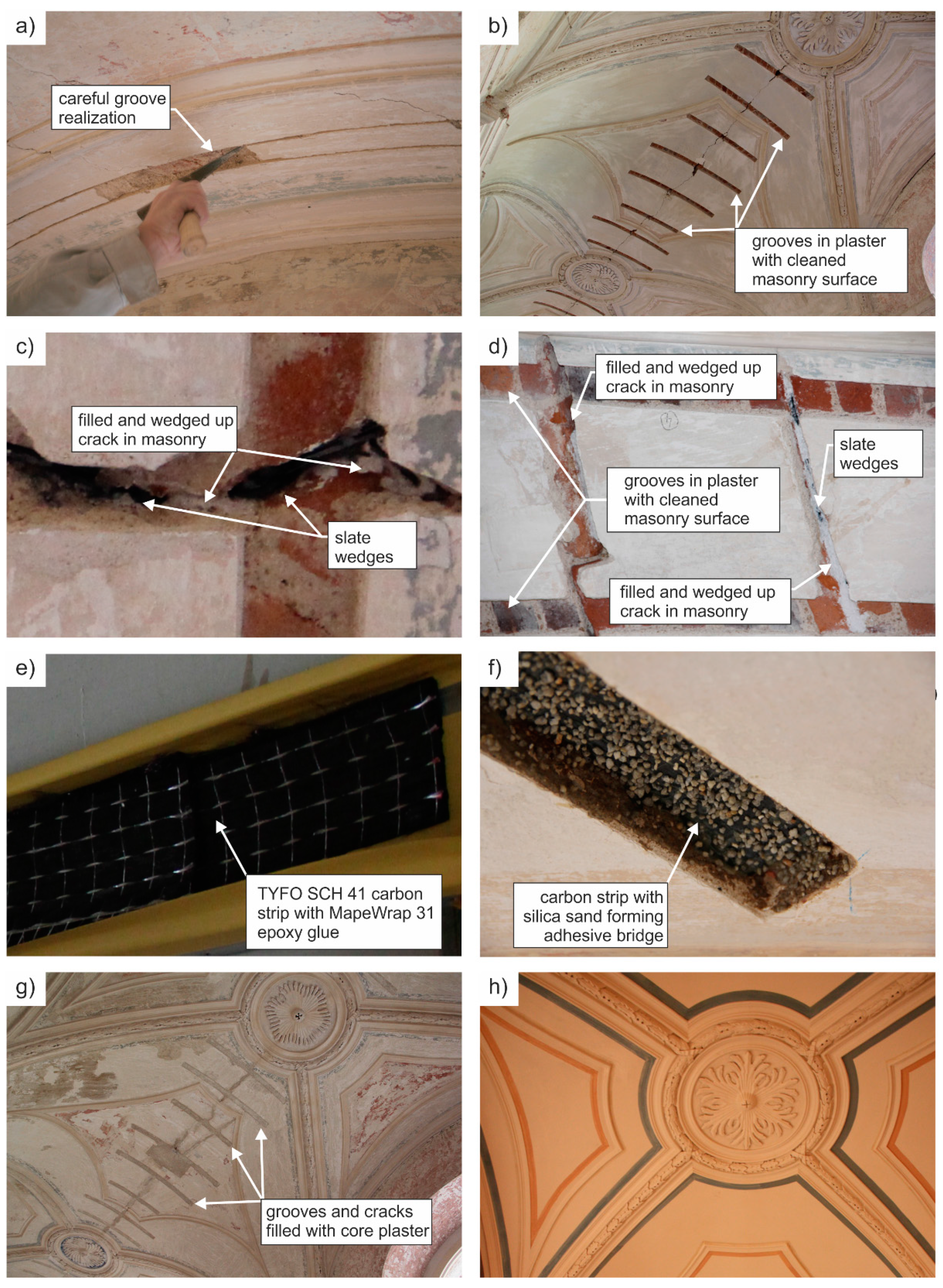
To ensure the reliability and limit the potential failure of the rehabilitation design of damaged vaults over the arcaded walk of the Monastery at Teplá to an acceptable level, complementary experimental research was carried out as part of the rehabilitation design, including the verification of the shear strength in the contact joint of the composite of high-strength fibers and vault masonry and experimental verification of static and deformation characteristics of a vault reinforced with strips of a non-prestressed composite applied in the vault soffit damaged by a tensile crack. Complementary research of the behavior and response of the additionally reinforced vault damaged by cracks and a vault partially undamaged by a tensile crack exposed to the effects of induced seismicity was also conducted. Based on the results of the complementary research, the final reinforcement design of the damaged historic barrel vaults in the arcaded walk of the Monastery at Teplá was further refined.
The following experimental verifications and theoretical analyses were performed:
(a) Efficiency of the effect of the reinforcement of a vault damaged by tensile cracks with strips of a non-prestressed composite applied in the vault soffit on the vault’s ultimate load.
The experimental research carried out in [
1] confirmed the growth in the ultimate bearing capacity of masonry barrel vaulted structures reinforced on their surface with non-prestressed composites of carbon or glass fabrics and epoxy resin [
12,
44]. The research ascertained that non-prestressed composite strips glued on the vault surface, particularly in the areas of tensile stresses, limited the appearance and development of tensile cracks enhancing vault stability.
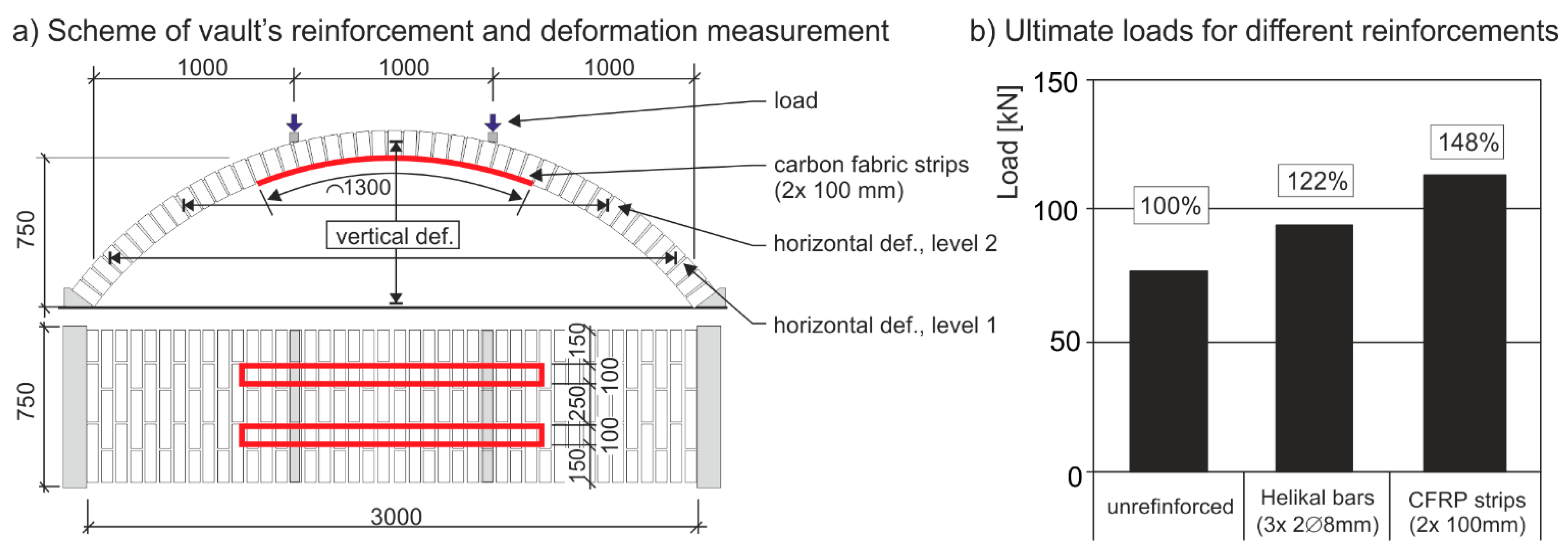
The static verification test proved the stabilization and a partial increase in the load-bearing capacity of the vault damaged by a tensile crack, reinforced with non-prestressed carbon composite strips (
Figure 9a) by
ca. 48% compared to the load-bearing capacity of a damaged unreinforced vault (
Figure 9b).
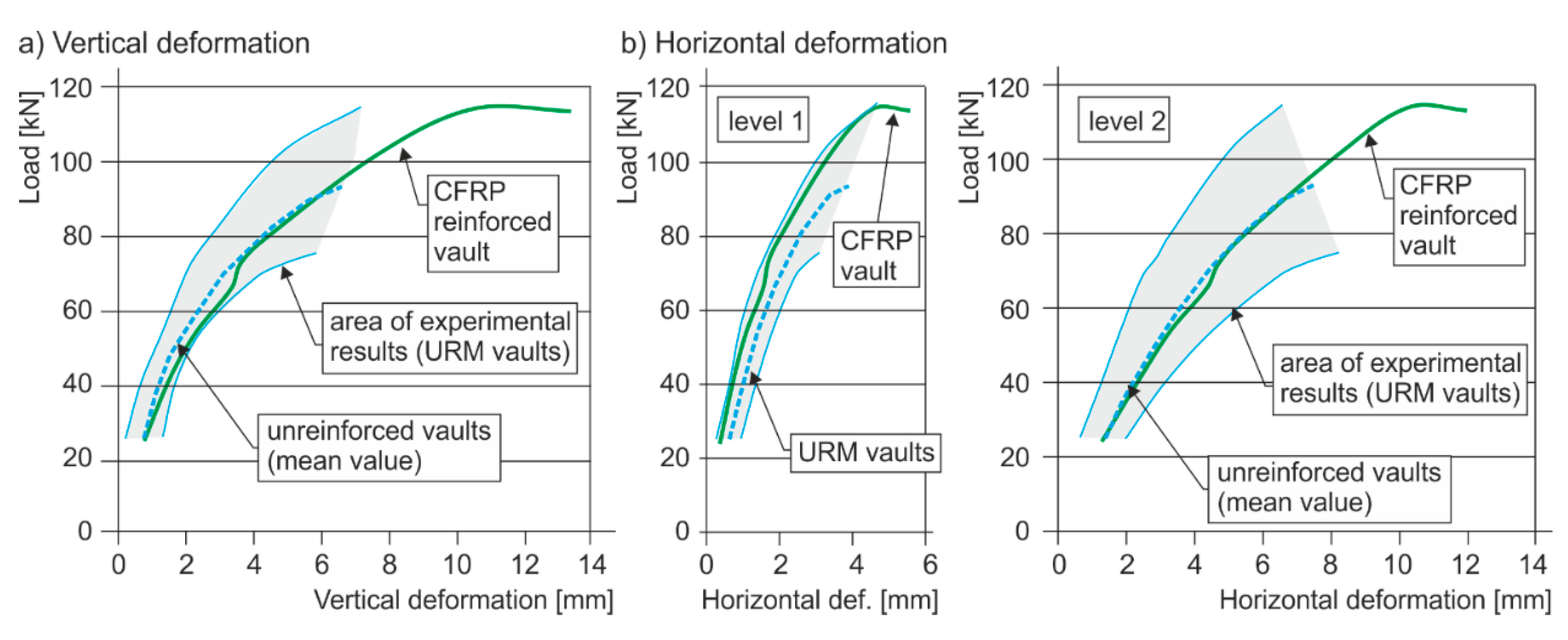
Figure 10 presents the load
vs. deformation diagrams of the vault without composite strips reinforcement and of the vault with composite strips reinforcement, which document the increased ductility and load-bearing capacity of the vault reinforced with carbon strips placed at the vault soffit’s crown.
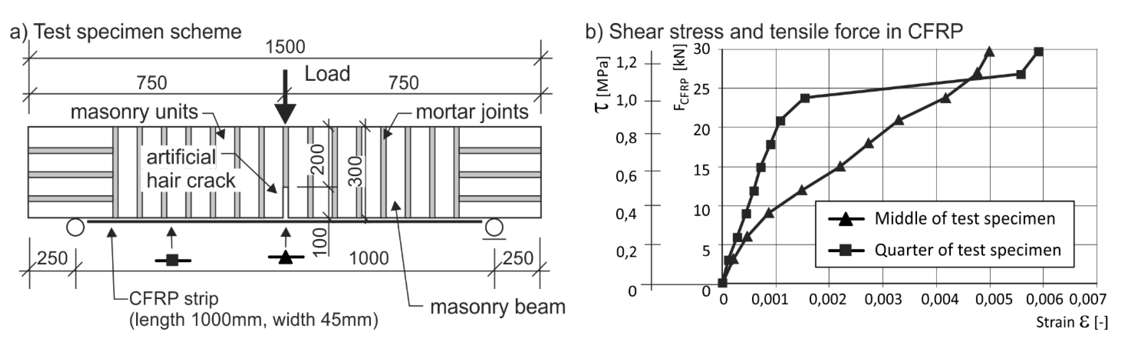
(b) Shear strength of the CFRP composite–masonry contact joint.
The experimental verification investigated the adhesion and shear strength of carbon composites strips glued onto masonry test pieces (”beams”) with the MapeWrap 31 epoxy resin (
Figure 11a). The ultimate tensile force of 29.8 kN at rupture was verified for a carbon composite strip 0.045 m in width with epoxy resin. The experimentally verified value of the ultimate “substitute uniform“ shear stress at break for the “composite–masonry” contact joint is 1.3 MPa (
Figure 11b). The actual shear force pattern in the contact joint is characterized by significant non-uniformity with the maximum shear forces in the strip anchoring area reaching values one order of magnitude higher. A similar shear force pattern may also be expected in the case of the rehabilitation design of a damaged vault, therefore, the above results are directly applicable. For a carbon composite strip 45 mm in width and 0.7 to 1.5 m in length applied for the vault stabilization, the ultimate force in one strip at the bond failure (shear strength) in the contact joint, calculated from the experimentally identified average shear stress of 1.3 MPa ranges from 20.4 to 41 kN. For the designed distances of carbon composite strips in the soffit of damaged barrel vaults over the arcaded walk of 0.45 m and the maximum values of tensile normal stresses +σ
x (0.63 to 0.95 MPa) (in the cross section of the vault crown due to the vertical loading and temperature gradient effect), which considering the stress pattern along the masonry cross section, the tensile forces in the strips reach values of 10.1 to 17.1 kN,
i.e., values lower than the experimentally verified ultimate tensile force in the strip of 29.8 kN and, as a consequence, lower average values in shear than the experimentally identified shear strength in the “composite–masonry” contact joint. The precondition for the reliable function of the designed solution is, above all, the quality and reliability of the “composite–masonry” adhesion, which may only be achieved in non-degraded sound vault masonry (after removing surfacing) and by the optimum placement of the anchoring areas of strips, together with a reliable system of vault tendons. A significant step in terms of long-term reliability of the rehabilitation and stabilization design is, in particular, the additional activation of steel tendons installed during the previous reconstruction 2nd OS (prestressing of tendons in the place of anchoring steel plates situated on the building’s façade).
Figure 9.
(a) Schematic of masonry barrel vault’s reinforcement with strips of carbon fabrics. (b) Ultimate loads for unreinforced and reinforced vaults (Helikal reinforcement was one of the originally considered stabilization methods for the arcade walk damaged vaults).
Figure 9.
(a) Schematic of masonry barrel vault’s reinforcement with strips of carbon fabrics. (b) Ultimate loads for unreinforced and reinforced vaults (Helikal reinforcement was one of the originally considered stabilization methods for the arcade walk damaged vaults).
Figure 10.
Load vs. vertical (a) and horizontal (b) deformation graphs for unreinforced and CFRP reinforced vaults.
Figure 10.
Load vs. vertical (a) and horizontal (b) deformation graphs for unreinforced and CFRP reinforced vaults.
Figure 11.
Experimental verification of the carbon strip–masonry bond: (a) test scheme and (b) shear stress to strain relationship.
Figure 11.
Experimental verification of the carbon strip–masonry bond: (a) test scheme and (b) shear stress to strain relationship.
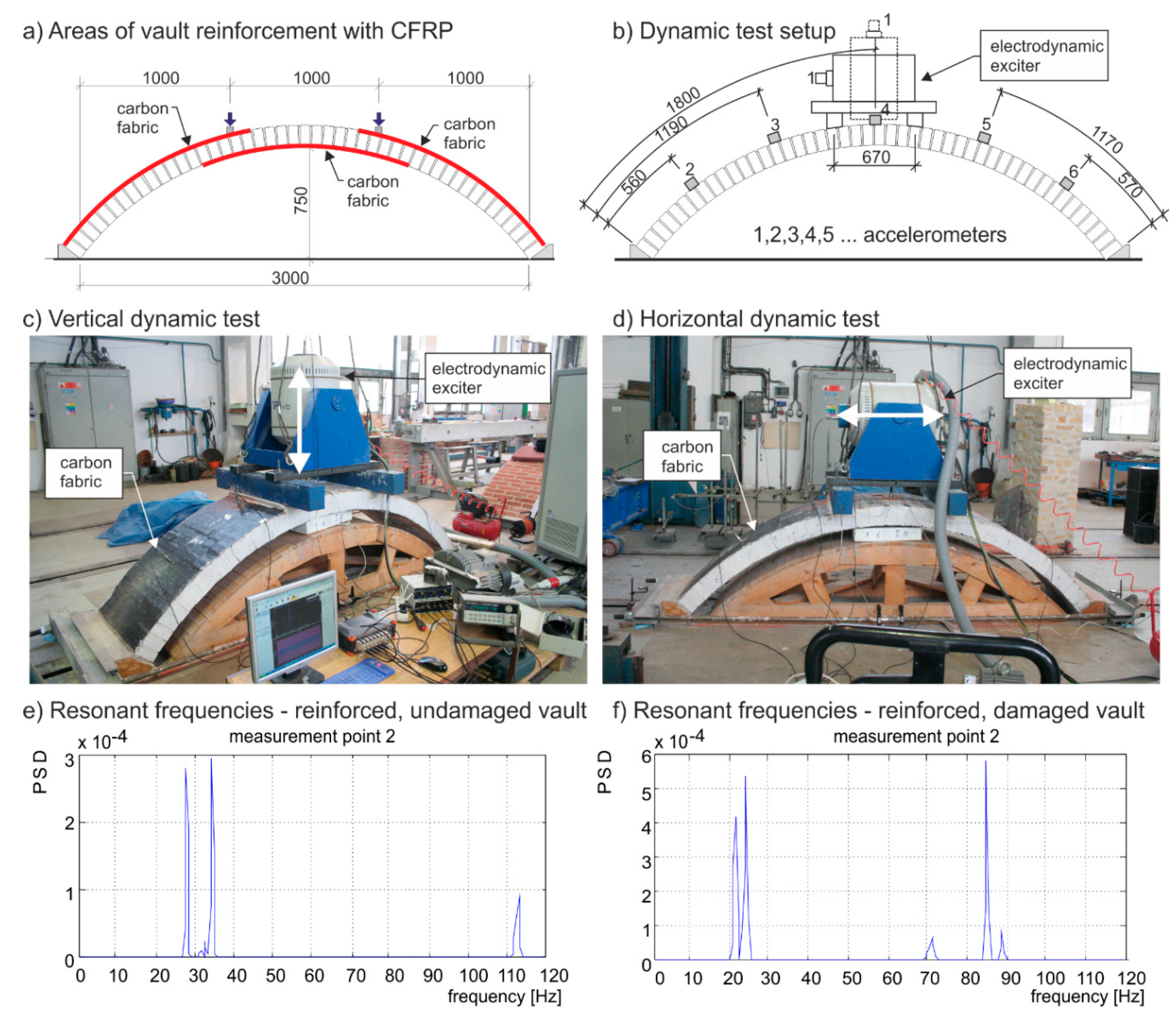
(c) Dynamic characteristics of segmented barrel vaults.
The Premonstrate Monastery is situated in a region characterized by seismic risks of up to 7° MSK-64. Seismic effects in this region are manifested by so-called seismic swarms. Increased seismic activity was last recorded there in 1997 and 2001.
The subject of the experimental research was the verification of the response and dynamic properties of a segmented barrel vault exposed to dynamic loading in the horizontal and vertical direction. The dynamic properties were verified for two cases:
Figure 12.
(a) Schematic of masonry barrel vault’s reinforcement with carbon fabrics; (b) schematic of mounting the electro-dynamic exciter and arrangement of accelerometers on the masonry vault; (c) electro-dynamic exciter for vertical oscillations; (d) electro-dynamic exciter for horizontal oscillations; (e) identified resonant frequencies before the reinforced vault’s failure; and (f) vault response spectra and identification of vault’s natural frequencies after the static test.
The presented results of dynamic tests were obtained for alternative (two-sided) vault reinforcement with FRP, which, however, was replaced with a simpler reinforcement method—FRP strips applied at the vault soffit in the final phase of the rehabilitation design based on the contractor’s technical abilities and requirements. The results should give a general idea of the potential effect of vault’s reinforcement with FRP in terms of resistance to seismic impacts.
The results of the tests on both vaults are summed up in
Table 3, which presents all loading states (A, B, C and D) and lists the extent of damage.
Table 3.
Identified resonant (natural) frequencies of tested vaults.
Table 3.
Identified resonant (natural) frequencies of tested vaults.
| Vault (state) | Frequency [Hz] |
|---|
| Undamaged (A) | After dynamic loading test 1 (B) | After static loading 2 (C) | After repetitive dynamic loading test (D) |
|---|
| reinforced | 28.08 | 27.47 (97.8%) 3 | 21.97 (78.2%) 3 | not identified |
| 112.61 | 102.54 (91.1%) 3 | 84.84 (75.3%) 3 | not identified |
| unreinforced | 25.94 | 20.75 (79.9%) 3 | 10.99 (42.4%) 3 | 9.16 |
| 106.81 | 96.44 (90.3%) 3 | 44.46 (41.6%) 3 | 42.72 |
Two resonance oscillation shapes were identified in both cases. The loading resulted in a frequency drop of the reinforced vault by ca. 25% due to the reduced effective stiffness of the structure. In the unreinforced vault, however, there was a prominent frequency drop compared to the reinforced vault by up to 65% of the original value, i.e., a marked reduction in the effective stiffness of the structure.
In both cases, the frequency analysis identified “intermediate” frequency peaks within the response spectrum. This corresponds to the vault consolidation and a gradual temporary change in the structural arrangement, which may be interpreted as the appearance of an articulated vault arch with multiple joints resulting from progressing damage. The natural modes of vibration, however, are not associated with these frequencies as they are “parasitic” frequencies, which cannot be compared with the original natural mode on an undamaged structure. Despite this, their drop was evident, too, as corresponds to the general loss in the elasticity of masonry. There was also a dramatic drop (practically down to zero) in oscillation amplitudes in the higher shape, which may be associated with higher damping of the respective shape due to the appearance of micro cracks inside the masonry.
The above-mentioned results must be interpreted with due caution for the case of the rehabilitation project (reinforcement by strips only in the vault soffit compared to the experimental dynamic test of a vault reinforced both in the soffit and at the back). Despite this, we may expect that vault reinforcement with CFRP strips enhances the vault resistance to potential damaged by dynamic loads.
(d) Theoretical parametric study of the segmented barrel vault stress state in relation to reinforcement with composite strips.
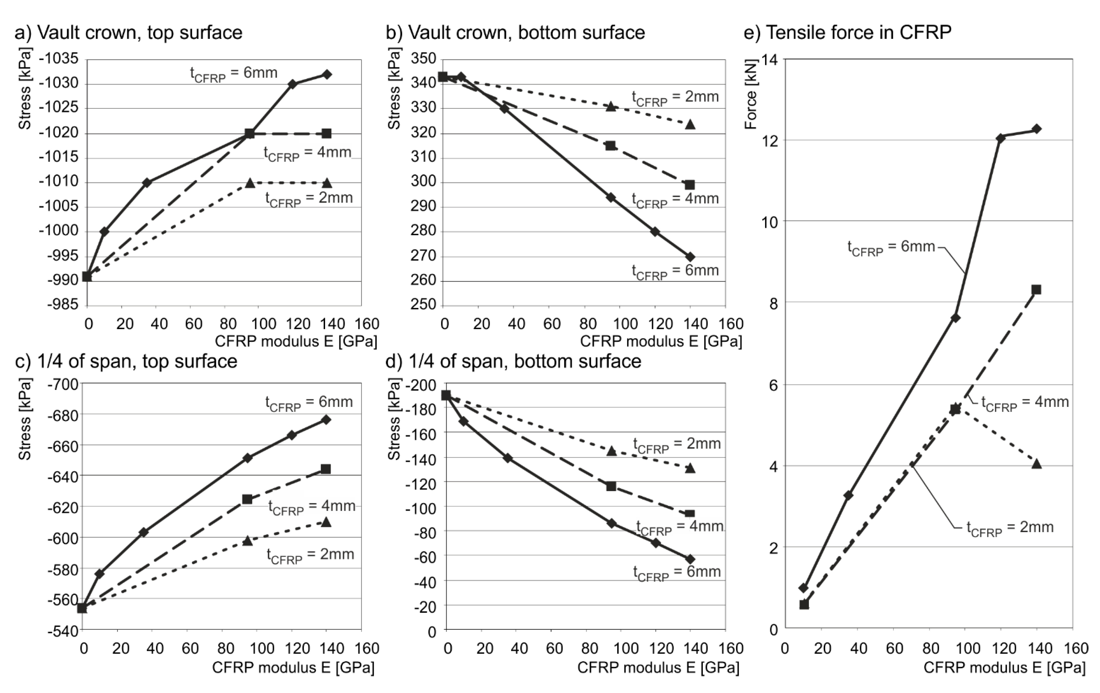
The subject of the supporting parametric study was to verify the stress state of a segmented barrel vault in relation to the thickness and the modulus of elasticity of the CFRP composite applied in the crown part of the vault soffit, i.e., in the area where tensile normal stresses appeared. The parametric study included the calculations of the vault’s stress state (first order calculation–linear) for different (theoretical) values of the carbon composite’s modulus of elasticity in tension E ∈ (0–140) GPa and different (theoretical) thicknesses of the composite ∈ (2; 6) mm (selected theoretical values). The numerical analysis was made for the case of vertical loading with the vault’s own weight and the weight of infill layers, for the case of the masonry modulus of deformation Ep = 4500 MPa and Poisson’s ratio n = 0.2.
The results of this theoretical parametric study are presented in
Figure 13, which shows the patterns of normal stresses σ
x (kPa) in selected cross sections of a barrel vault in relation to the vault reinforcement with a composite glued by epoxy resin onto the cleaned vault masonry surface. Within the range of the values of the composite’s elastic modulus in tension
Ek there was a drop, or growth in the normal stresses ±σ
x in the peripheral fibers of monitored sections by
ca. 4% to 25% (up to 75%) compared to the unreinforced vault. On the contrary, there was a significant growth in the tensile force
Fk at a value of
Ek,max = 140 GPa in the composite, compared to the tensile force value corresponding to
Ek,min = 10 GPa.
The listed σ × Ek, or σ × tk relations imply a certain fall in the “effectiveness” of the composite expressed by the increment, or the decrement in the monitored values of normal stresses ±σx in the vault masonry and the tensile force in the composite Fk. The explanation must be sought in the mechanism of the “masonry–composite“ mutual interaction—the carbon composite is activated due to the effect of forced deformation, which depends on the tensile deformation of the masonry and the stiffness of the carbon composite (Ek × tk). The growing stiffness is accompanied by a drop in the vault masonry deformation.
Figure 13.
Comparison of stresses depending on the CFRP modulus and thickness: (a) crown of the vault (top surface); (b) crown of the vault (bottom surface); (c) 1/4 of the vault span (top surface); (d) 1/4 of the vault span (bottom surface); and (e) comparison of tensile force in CFRP reinforcement depending on the CFRP modulus and thickness.
A drop in tensile normal stresses +σ
x on the lower edge at the vault’s crown in relation to the carbon composite strip’s stiffness (
Ek ×
tk) is accompanied by a drop in compressive normal stresses −σ
x, or by a rise in tensile stresses +σ
x on the lower edge of the vault in the anchoring areas of composite strips situated in a part of the vault’s soffit. These “increments” in tensile normal stresses +σ
x in the composite anchoring areas may be, in relation to the initial stress state of the vault, additionally covered by sufficiently large compressive normal stresses −σ
x in the area of the composite anchorage −σ
x. At a low value of −σ
x in the anchoring area (low compressive prestress), the tensile stresses +σ
x may exceed the “original” compressive stress −σ
x and cause a rise in tensile stresses +σ
x in the area of composite anchorage together with a successive appearance of tensile cracks. In these cases, the degradation of the composite and the loss in its effect may be expected. To prevent this state, the composite’s anchoring areas should be placed in the vault parts with strong and non-degraded masonry and with a sufficient initial “reserve” of the compressive stress −σ
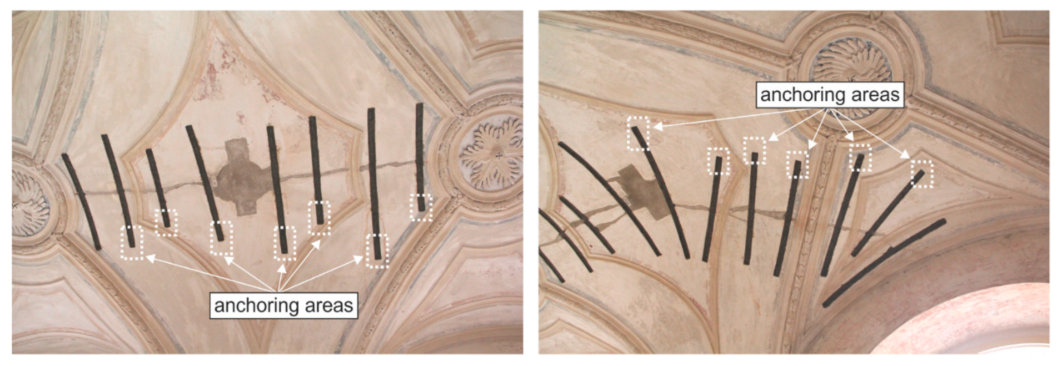
x due to permanently acting loads (weight of embedded structures). In this context, the alternation of anchoring areas of neighboring carbon composite strips may positively apply (
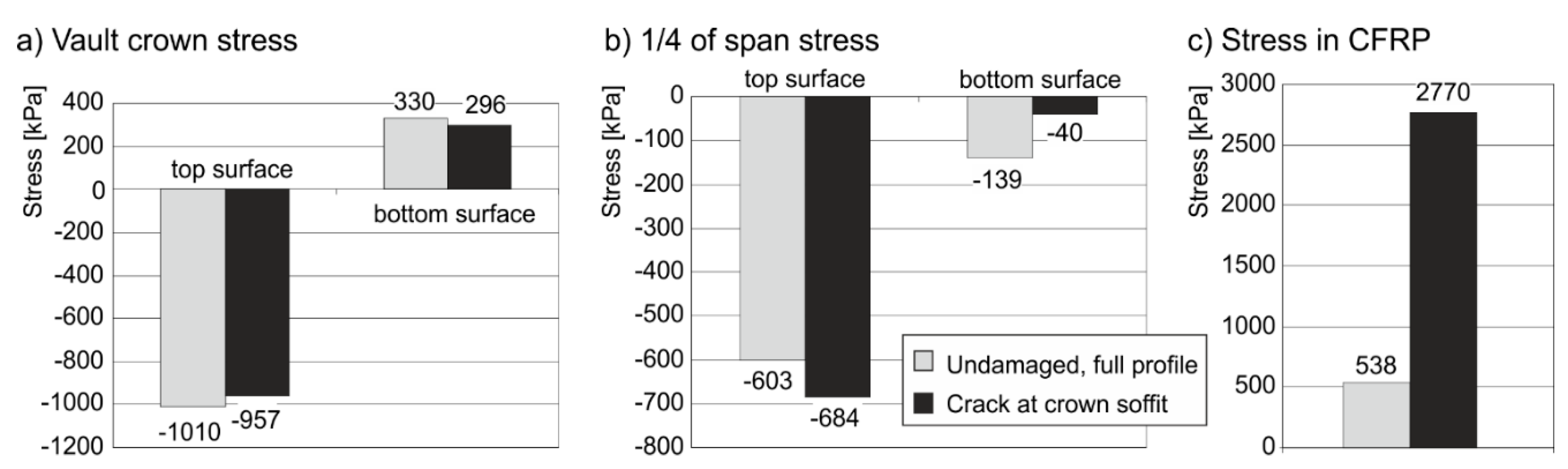
Figure 14). Sufficient reserves in the “composite–masonry” bond in the contact joint are required to secure the effectiveness and reliability of the system of composite strips. In the case of a vault reinforced with composite strips (
Ek = 30 GPa,
tk = 6 mm), crack appearance or the application of composite strips on a vault damaged at the crown by a tensile crack extending to
ca. 1/2 of the vault cross section’s height, is accompanied by a significant redistribution of stresses ±σ
x in the vault masonry and by a steep growth in the tensile force in the carbon composite compared to the case without a crack (
Figure 15).
The findings obtained from the parametric study were reflected within allowable limits (heritage conservation requirements) in the final stabilization design of damaged vaults.
Figure 14.
Alternation of anchoring areas of neighboring carbon composite strips.
Figure 14.
Alternation of anchoring areas of neighboring carbon composite strips.
Figure 15.
(a) Stress comparison at the reinforced vault crown with and without the initial crack; (b) Stress comparison at the reinforced vault 1/4 of span with and without the initial crack; (c) Stress comparison at the CRFP reinforcement with and without the initial crack.
Figure 15.
(a) Stress comparison at the reinforced vault crown with and without the initial crack; (b) Stress comparison at the reinforced vault 1/4 of span with and without the initial crack; (c) Stress comparison at the CRFP reinforcement with and without the initial crack.


 ,
, 


