Article

RC Columns Strengthened with Novel CFRP Systems: An Experimental Study

Department of Civil Engineering, University of Salerno, Via Giovanni Paolo II 132, Fisciano (SA) 84084, Italy
*
Author to whom correspondence should be addressed.
Polymers 2015, 7(10), 2044-2060; https://doi.org/10.3390/polym7101499
Submission received: 4 August 2015 / Revised: 8 September 2015 / Accepted: 10 October 2015 / Published: 19 October 2015

Abstract

:
This paper presents an experimental study undertaken to investigate the seismic behavior of full scale square (300 mm × 300 mm) reinforced concrete (RC) columns strengthened with novel systems employing carbon fiber-reinforced polymers (CFRP) wraps. Experimental tests were carried out by subjecting specimens to a constant axial load and a cyclically reversed horizontal force applied in displacement control. Results have allowed for investigating the influence of the used strengthening systems on the specimens’ performance in terms of flexural strength and ductility as well as on the exhibited failure modes. The effectiveness of the studied techniques is also evaluated by comparing the performance of tested specimens with that of companion columns strengthened with alternative CFRP systems investigated in a previous experimental campaign.

1. Introduction

Recent earthquakes have frequently highlighted the vulnerabilities of existing reinforced concrete (RC) structures to seismic deformation and shear demands. It is known that the most building heritage dating back to the 1970s was designed in order to withstand only gravity loads or according to outdated seismic rules. In particular, these “under-designed” structures are often characterized by an unsatisfactory weak column-strong beam behavior that, under a seismic event, most likely yields to the formation of local hinges in the columns and to a consequent low available global ductility.
In order to improve the strength and mainly the rotational ductility of RC columns, external confinement systems employing fiber-reinforced polymers (FRP) are now frequently proposed as a viable alternative to traditional strengthening measures, mainly consisting of steel or concrete jacketing.
The growing interest in the FRP materials is confirmed by both the great variety of experimental investigations performed by researchers and the number of analytical models published in the literature to predict the compressive strength, the corresponding ultimate axial strain and the stress-strain constitutive law of the FRP confined concrete. National and International design guidelines are also available [1,2,3].
Most experimental tests were performed in uniaxial compression on small scale concrete specimens variably confined by using carbon (C) or glass (G) FRP layers applied via wet-layup; the efficacy of the reinforcement on different cross-sections was examined with emphasis on the circular shape for which an updated database of experimental results can be found in the literature [4,5].
A relatively limited number of experimental studies were carried out on full scale FRP confined circular or rectangular RC columns subjected to axial load and cyclic flexure [6,7,8,9], and few studies take into account the presence of smooth steel rebars as longitudinal reinforcement of specimens [10,11,12,13].
In these studies, it has been widely proven that the FRP confinement significantly improves the ductility of columns; conversely, in presence of cyclic bending, it is not sufficient by itself to provide a comparable increase of strength which is often desired by structural engineers; the reduced performance in terms of strength gain is mainly experienced when the axial load level in the column is low and even more evident in the case of non-circular cross sections.
To address this issue, in a previous experimental investigation the authors have examined the effectiveness of a strengthening layout characterized by the combined use of FRP confinement and longitudinal L-shape steel profiles connected to the concrete stub by means of a steel anchorage system [12,13]. It was demonstrated that such a technique is capable of significantly increasing the flexural strength but a reduction of the available ductility with respect to columns confined with FRP only is observed due to the premature failure of the profile’s anchorage system.
In order to overcome this drawback and the issue related to the not ease of installation of the studied technique (in particular of the profile’s connection systems), the authors have experimentally investigated the feasibility of two alternative strengthening solutions for full scale RC columns, and the results are discussed in this paper. The first solution consists of placing four steel threaded rods inside concrete grooves which were adhesively bonded into the foundation for a length of about 250 mm; then, the strengthening is completed by external CFRP confinement. The second solution, instead, differs from the first one in a way that additional L-shape steel profiles have been used at the column corners before applying the CFRP confinement.
Columns included in the experimental campaign were reinforced by using deformed steel rebars and manufactured with medium/low concrete compressive strength; the reinforcement details (i.e., lap splice lengths, hoop spaces, etc.) were arranged following design rules used in the past and without keeping into account any seismic details.
Tests were carried out at the Laboratory of Materials and Structural Testing of the University of Salerno by subjecting specimens to a constant axial load and a cyclically reversed horizontal force applied in displacement control.
The experimental results have allowed for investigating the influence of the two abovementioned strengthening systems on the specimen performances in terms of flexural strength and ductility as well as on the exhibited failure modes. Finally, the analysis of the nonlinear cyclic behavior of strengthened members has allowed to draw useful information about the stiffness degradation and the energy dissipation phenomena. The performance of tested specimens was also compared with that of FRP strengthened columns examined in the previous experimental campaign [12], and advantages and drawbacks of the explored techniques were also highlighted.

2. Experimental Section

The experimental program included 5 full scale RC columns subjected to cyclic flexure under constant axial load. Of these, four members were strengthened by CFRP systems whereas the remaining one was used as control (unstrengthened) specimen; the latter, after being damaged, was also repaired, strengthened with FRP and re-tested. Details about RC specimens are reported in the following.

2.1. Specimens

Test specimens have a square 300 × 300 mm2 cross section, a length of 2200 mm and a concrete stub of 1400 × 600 × 600 mm3. They were designed to simulate structural components belonging to gravity load designed existing buildings. For this reason, the concrete mix was chosen to obtain a mean value of the compression strength, fcm ≈ 16–19 MPa, which is frequently found in RC buildings built in the 1960–1970s; the actual value of the concrete strength per column was estimated by testing in compression a set of three 150 mm edge cubic samples, cast along with the column and cured under the same environmental conditions.
In addition, the steel reinforcement details were arranged without any particular care for seismic considerations. Figure 1 illustrates the configurations of the longitudinal and transverse deformed steel reinforcement adopted for the specimens which are the same already considered in the previous experimental campaign [12]. As shown, the longitudinal reinforcement, made of steel grade “B450C” [14], consisted of six 14 mm diameter rebars having a lap splice length at the column-base joint equal to about 40 bar diameters (≈600 mm), as frequently used in Italy; a clear concrete cover of 27 mm was considered at the both sides of the cross section. Tensile tests were performed on small samples to characterize the yield (fsy) and the ultimate strength (fsu) of the steel longitudinal rebars and the corresponding strains (εsy and εsu); from these tests the following average values were found: fsy = 490 MPa and εsy = 0.23%; fsu = 619 MPa and εsu = 11.78%.
The transverse reinforcement, made of the same steel grade as for longitudinal rebars, consisted of 8 mm diameter steel stirrups; 200 mm spaced and closed with 90° hooks at both ends.
Figure 1. Details of RC specimens.
Polymers 07 01499 g001

2.2. Strengthening Layouts

Figure 2 shows the two strengthening layouts investigated in the experimental campaign which were designed in collaboration with Italian company “Interbau Srl” [15].
The system “type A” (Figure 2a) entailed the use of four (2 + 2) M16 threaded steel rods (tensile strength ≈ 635 MPa), which were placed with mortar inside grooves cut into the concrete. These rods integrating the pre-existing longitudinal steel reinforcement (3 + 3Φ14), crossed the column for a height of about 1450 mm and were anchored with epoxy resin into the concrete foundation for a length of about 250 mm. Then, the column strengthening was completed by a passive confinement obtained with unidirectional CFRP layers. In particular, starting from the column base, the first portion of the member (of about 450–500 mm) was continuously wrapped by using one or two CFRP plies, while the remaining part was strengthened employing a single layer of 150 mm spaced strips, each having a width of 100 mm; the overlap length between layers in the transverse direction was about 300 mm. It is highlighted that the layout of the CFRP confinement was the same already used in the previous experimental campaign [12], and the length of the region with continuous wrapping was based on previous theoretical estimates performed on the development of the plastic hinge zone. In addition, the choice of using two CFRP plies for the continuous wrapping was always based on considerations drawn by experimental tests previously performed by the authors; indeed, in those tests it was shown that the employment of only CFRP confinement with two layers was sufficient by itself to provide an appreciable increase of the flexural strength of the columns. In the experimental campaign discussed herein, instead, it was decided to also investigate the change in the load-carrying capacity of the column when only one CFRP layer was employed as continuous wrapping, since the system “type A” included the use additional steel rods.
Figure 2. Strengthening layouts: “type A” (a); “type B” (b).
Polymers 07 01499 g002
In order to prevent stress concentrations—which may cause the premature failure of the FRP system—the column’ corners were rounded to a radius of approximately 30 mm before applying the FRP jacket.
As provided by supplier, the employed CFRP sheets had an elastic modulus of 390 GPa, a tensile strength of 3000 MPa and an ultimate strain of 0.80%; the thickness of the single layer was ≈0.22 mm. The thixotropic, two part adhesive used to bond the external CFRP reinforcement, instead, was characterized by an elastic modulus equal to 9600 MPa and 11,200 MPa in compression and tension, respectively, and required a 7-days curing time to achieve optimal performances; additional information on the mechanical properties of the used adhesive can be found in the technical sheets provided by the manufacturer [16].
The system “type B” (Figure 2b), instead, also entailed the use of longitudinal cold bent steel profiles along the member corners before applying the external wrapping made of two CFRP layers; they were four 80 mm × 80 mm × 6 mm equal leg angles made of structural steel S235. The angles were glued to the concrete substrate by an epoxy adhesive and were properly manufactured in order to have a rounded corner with a radius of about 30 mm. After placing the angles and before manufacturing the FRP jacket, a 6 mm layer of epoxy mortar was applied on each column side, in order to fill the gap between the profiles (see the detail in Figure 2b).
Figure 3 and Figure 4 show some details about the strengthening procedures used for the considered layouts “type A” and “type B”, respectively. In particular, Figure 3a illustrates the shape of the threaded rods used for internally reinforcing the RC columns, pre-bent at one end in order to be inserted into the concrete foundation; Figure 3b,c show the status of the column after: (a) cutting the outer portion of the concrete surface; and (b) filling the grooves and covering the threaded rod with mortar. Finally, Figure 3d depicts the column at the end of the strengthening procedure "type A”.
Figure 3. Strengthening procedure: layout “type A”.
Polymers 07 01499 g003
Figure 4. Strengthening procedure: layout “type B”.
Polymers 07 01499 g004
Regarding the strengthening procedure “type B”, Figure 4a,b illustrate the placing of the steel rods inside the concrete groves, the filling with mortar and the arrangement of the steel angles at the columns corners; Figure 4c,d show, respectively, the subsequent operations dealing with the application of a 6 mm mortar layer on the column and the CFRP external confinement. Finally, Figure 4e depicts the column at the completion of the strengthening procedure “type B”.

2.3. Test Set-Up

The test set-up, as shown in Figure 5, is very similar to that already used in the previous experimental campaigns; therefore, specific details, omitted for the sake of brevity, can be found in [12].
Tests were carried out by subjecting the specimens to combined axial and lateral loads. The specimens were restrained to the lab’s floor by means of a steel system which consisted of: (a) two transverse beams placed on the RC foundation and fixed to the floor by means of four high strength thread rods that were properly pre-tensioned in order to avoid any stub rotation; and (b) two stiff steel plates fixed onto the ground and placed orthogonally to the load direction at the bottom of the stub in order to prevent any horizontal movement.
The axial load (N) was applied before the horizontal one by pre-tensioning a pair of 40 mm diameter high strength steel rods with a 2000 kN MOOG hydraulic actuator: this actuator, placed at the top of the column, kept the axial load constant during each test. A value of the normalized compression load “ν” equal to 0.40 was considered for five tests, whereas for the remaining one ν = 0.14 was adopted; this parameter is given by N/(Ag fcm), where Ag is the column cross-section area.
Figure 5. Test set-up.
Polymers 07 01499 g005
The horizontal action, instead, was cyclically applied in displacement control by using a 250 kN MTS hydraulic actuator, mounted at 1700 mm from the column base and fixed to a reaction steel frame. An increment of the imposed horizontal displacement every three cycles was considered in order to evaluate the strength and stiffness degradation at repeated lateral load reversals. In particular, after initial cycles performed at 1, 2, 4, and 6 mm, the displacement amplitude was given as fraction of the estimated top yield displacement of the column, Δy (≈20 mm for columns tested under ν = 0.40 and ≈17 mm for the column tested under ν = 0.14). Two different displacement rates were considered during the tests: 0.1 mm/s before the achievement of Δy and 1 mm/s after Δy.
Tests were stopped well beyond a predetermined “conventional collapse” corresponding to the 15% strength degradation evaluated on the monotonic envelope of the load-displacement curves. Loads, strains, displacements and crack widths were measured during tests as already done in the previous experimental campaign [12]. In particular: (a) horizontal and vertical strains have been monitored using several surface strain gauges placed of the CFRP wrap at about 100 mm from the stub face; (b) longitudinal strains of the steel angles were also recorded by positioning strain gauges on each profile; (c) one potentiometer was used to measure lateral displacements at 1700 mm from the column base (i.e., where the lateral load is applied); and (d) vertical displacements and crack widths at the column-stub interface were monitored by using four LVDTs placed at about 100 mm from the base. In particular, two LVDTs for each side were positioned and one of them had the pin located at 30 mm from the column base; in this way, the difference between the readings of two LVDTs allowed estimating the crack opening at the base and the slip of the outer rebars.

3. Results

Table 1 summarizes the main data and results of the six tests performed in the latest experimental campaign.
Each test is identified by a label providing the following information: the column number (from C1 to C5) with the addition of “N” (i.e., “new”) to distinguish these tests from those of the previous experimental campaign [12]; the strengthening system (type ‘‘A’’ or ‘‘B’’ in Figure 2a,b, respectively). It is noted that the test C1Nr-A refers to the control specimen C1N that, after being tested, was repaired and FRP retrofitted according to the layout “type A”. The repairing procedure consisted of: (a) removing the damaged concrete surface in the first portion of the column (≈200 mm), where a slight phenomenon of rebars’ buckling was observed at the end of the test C1N; (b) cleaning and filling the missing concrete with proper fiber reinforced mortar, and (c) subsequently applying the FRP system “type A”.
In addition to information about the FRP strengthening layout and the number of FRP layers employed for the continuous wrapping of the column, Table 1 reports: the actual value of fcm estimated per each column by testing in compression a set of three 150 mm edge cubic samples; the normalized value of ν and the corresponding applied axial load N; the peak lateral strengths in the two directions of loading (F+max and Fmax), the corresponding displacements (Δ+ and Δ) and the maximum displacements of the column (Δ+85% and Δ85%) measured at the conventional collapse.
Table 1. Test results.
Strengthening SystemTest# FRP LayerfcmνNF+maxFmaxΔ+ΔΔ+85%Δ85%
(MPa)-(kN)(kN)(kN)(mm)(mm)(mm)(mm)
unstrengthenedC1N-19.40.4070068.769.330.029.961.054.0
Type AC1Nr-A219.40.4070096.8100.149.950.0109.2102.9
Type AC4N-A115.30.4055090.387.340.040.077.680.2
Type AC3N-A219.00.4068097.8106.250.050.0118.986.4
Type BC2N-B217.90.40645107.9113.229.040.070.3104.4
Type BC5N-B217.40.1422078.782.233.534.078.765.8
unstrengthenedC9-D-31.80.1336571.0866.3242.642.2--
Type A1C15-D-A1222.00.14278110.7110.850.950.992.492.8
Type A1C24-D-A1215.00.40540119.8112.449.949.9134.3103.5
With the aim to better compare the effectiveness of the considered strengthening techniques, Table 1 also reports data and results of three tests performed in the previous experimental campaign, namely C9-D, C15-D-A1 and C24-D-A1 [12], for which the maximum displacements reported herein were computed at 85% conventional collapse (not available for the test C9-D). These specimens had the same geometry and steel reinforcement configurations of those used for the new test members. Except for the specimen C9-D, that was unstrengthened and used herein as control specimen for the only test performed under ν = 0.14 (i.e., test C5N-B), the other members were strengthened using a system “type A1” (see 
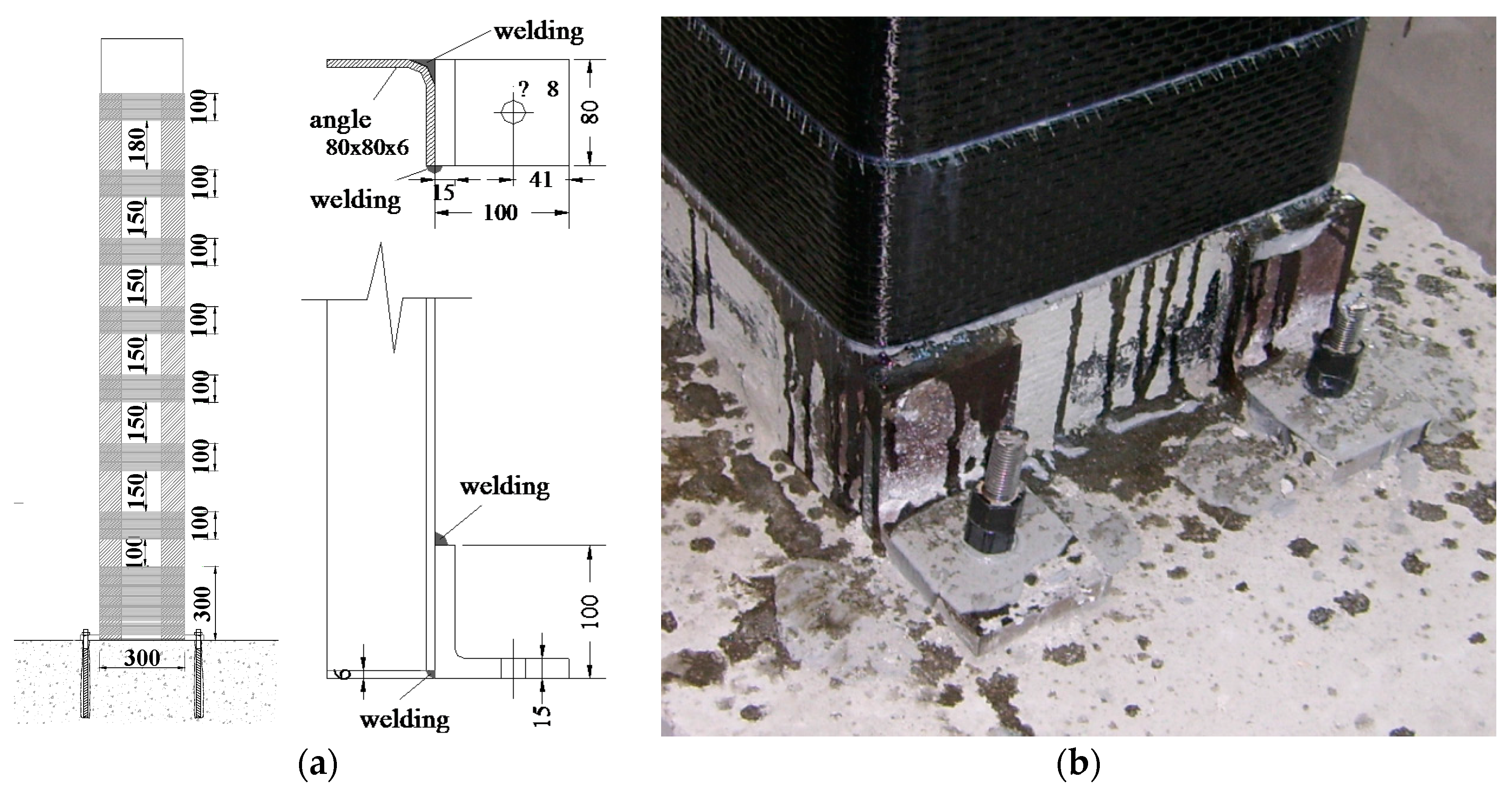
Figure 6a,b). As mentioned earlier, such a system is characterized by the combined use of CFRP confinement and steel profiles placed at the column’s corners and connected to the foundation by using an L-shape steel system. The layout of FRP confinement and the arrangement of steel profiles are the same of those in Figure 2b, whereas details on the anchorage system of such profiles, illustrated in Figure 6b, can be found in [12].
Figure 6. Strengthening systems “type A1” (a); details of steel profile’s anchorage system (b).
Polymers 07 01499 g006
It is worth noting that, as it can be observed in Table 1, the compressive strengths of concretes used for manufacturing the specimens C15-D-A1 and C24-D-A1 are rather comparable to those of the “new” test specimens; conversely, the specimen C9-D is characterized by an fcm value significantly greater than the other concrete strengths thus affecting a direct comparison with the test C5N-B. In addition, it is highlighted that a value of ν slightly lower than 0.14 (ν = 0.13) was used for the test C9-D, due to technical issues of the testing machine.
The following sections better detail the discussion of the test results.

3.1. Cyclic Curves

Figure 7 and Figure 8 show the lateral force (F)–displacement (Δ) hysteretic curves and the corresponding 
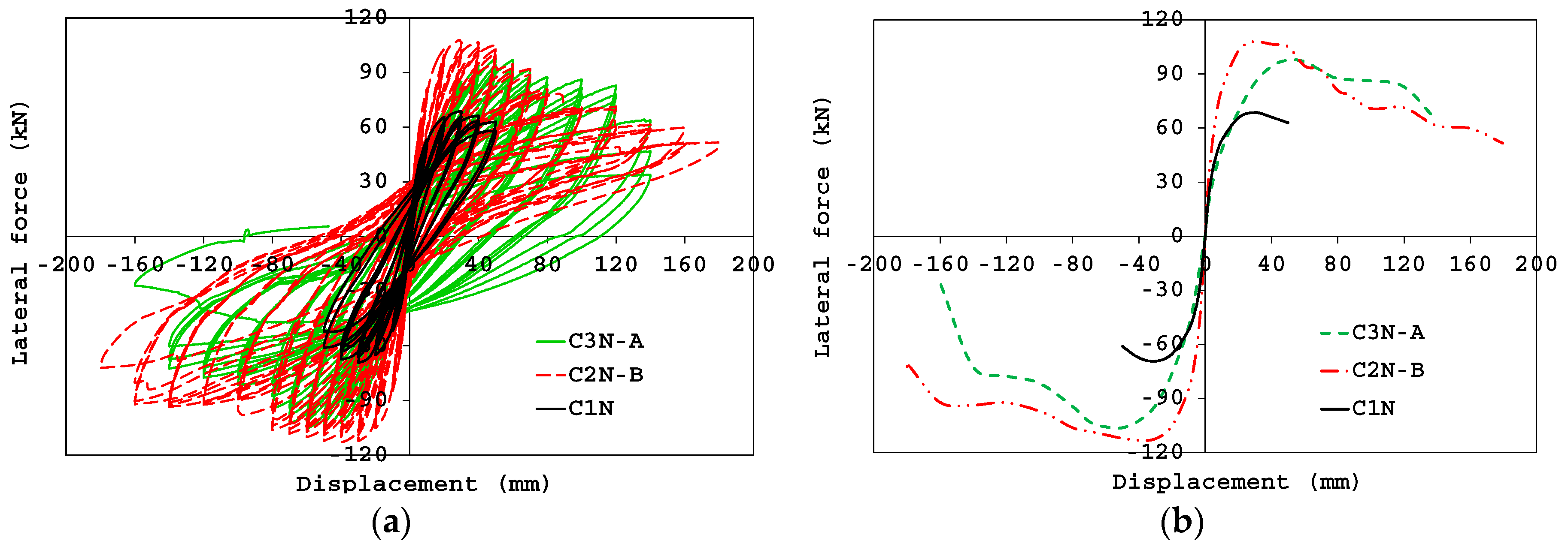
F–Δ envelopes for some tested specimens. In particular, in Figure 7a the cyclic response of the control specimen (C1N) is compared with the performance of two members strengthened with the FRP systems “type B” and “type A” (samples C2N-B and C3N-A, respectively).
Figure 7. F–Δ hysteresis curves (a) and envelopes (b): columns C1N, C2N-B and C3N-A.
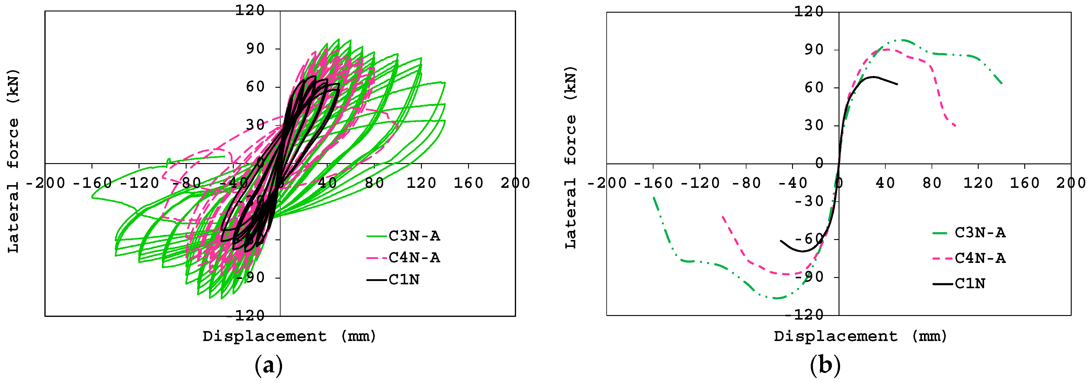
Polymers 07 01499 g007
Figure 8. F‒Δ hysteresis curves (a) and envelopes (b): columns C1N, C3N-A and C4N-A.
Polymers 07 01499 g008
As expected, the reference column experienced a rapid degrading behavior in the post-peak phase and achieved the collapse under low values of the imposed displacement. Disregarding the type of strengthening system, the specimens C2N-B and C3N-A have exhibited significant increases of strength over the control specimen (about 60% and 48%, respectively). The improvement of the column’s confinement through the use of steel profiles avoided the rupture of the FRP wrapping and delayed the crushing of concrete; indeed, after achieving the conventional collapse, the sample C2N-B showed a less degrading behavior with respect to the sample C3N-A and was capable of still undergoing significant lateral displacements. It is highlighted that the failure of two additional steel rods (on the same column’s side), due to a slight slippage combined to a fatigue phenomenon, was observed for the specimen C2N-B at imposed displacements of 90 and 120 mm (corresponding to lateral loads in the post-peak phase equal to about 78 and 70 kN, respectively.
Figure 8a,b shows the dependence of the cyclic response on the number of FRP layers employed for the continuous wrapping at column base; the F–Δ comparisons clearly highlight the beneficial role of using a double layer of CFRP layers in improving the deformation capacity of specimens. In particular, it is observed that the lateral displacement exhibited by the specimen C3N-A at the conventional collapse is about 30% over that measured for the counterpart confined with a single FRP layer; an increase of flexural strength equal to about 15% is also computed.
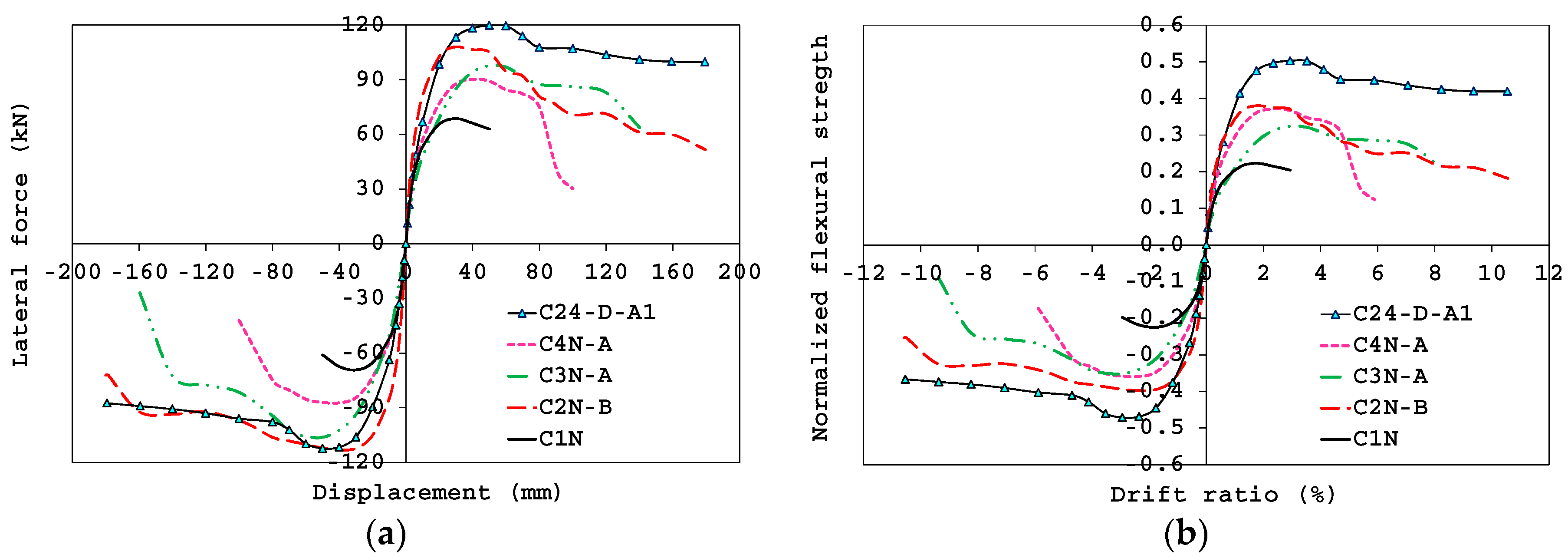
Figure 9a shows the F–Δ monotonic envelopes of test specimens subjected to ν = 0.40 which are also compared with the curve of the column C24-D-A1 [12]. Furthermore, in order to by-pass the dependence of the response on the concrete strength value, in Figure 9b the experimental results have been represented in terms of normalized flexural strength–drift ratio (μ–δ) curves. μ and δ are given by:
μ = F · L s B · H 2 · f c m = M B · H 2 · f c m ;   δ = L s
where B and H are the width and depth of the column cross section, respectively; F is the horizontal force applied by the actuator and Δ the corresponding displacement; Ls (=1700 mm) is the column’s shear span.
Figure 9. F‒Δ envelopes (a) and μ‒δ envelopes (b) under ν = 0.40.
Polymers 07 01499 g009
From the experimental 
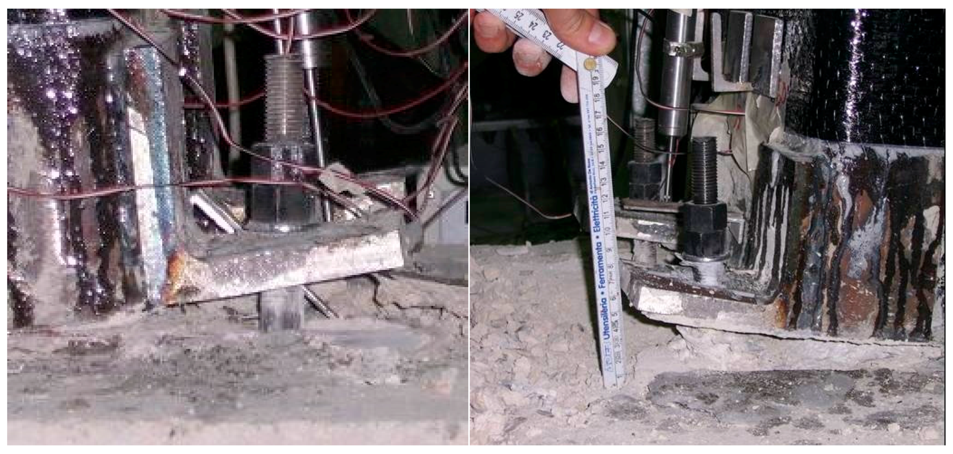
F–Δ comparisons it is noted that the strengthening system “type A1” provides increases of flexural strength and ductility slightly greater than those obtained through the layout “type B”; conversely, as mentioned earlier, this beneficial effect is offset by the need of time consuming and labor-intensive operations to provide a proper installation of the anchor system of steel profiles; on site, such installation is even more difficult when the anchoring of column’s steel profiles is made into a beam member rather than a concrete foundation. In addition, the strength increase progressively reduces with the occurrence of the slipping of the steel connector linking the profile’s anchor system to the concrete foundation, as shown in Figure 10 [12]; therefore, the performance provided by the use of a system “type A1” strongly depends on the proper design of the steel profile’s anchoring to the concrete beam/foundation.
Figure 10. Pull-out of the steel connector from the concrete foundation.
Polymers 07 01499 g010
Figure 11 allows for investigating the influence of the axial load level ν on the experimental response of specimens strengthened with the system “type B”. For this purpose, Figure 11a shows the comparison between the F–Δ cyclic curve of column C2N-B and that of the specimen C5N-B, subjected to ν equal to 0.40 and 0.14, respectively; Figure 11b, instead, depicts the corresponding F‒Δ envelopes, with the addition of the curve related to the reference specimen C1N, available for ν = 0.40.
As expected, the presence of a higher axial load approximately produces a 37% strength increase, thus confirming the beneficial effect of the CFRP confinement for significant values of the acting axial load.
Figure 11. F‒Δ hysteresis curves (a) and envelopes (b): columns C2N-B (ν = 0.40) and C5N-B (ν = 0.14).
Polymers 07 01499 g011
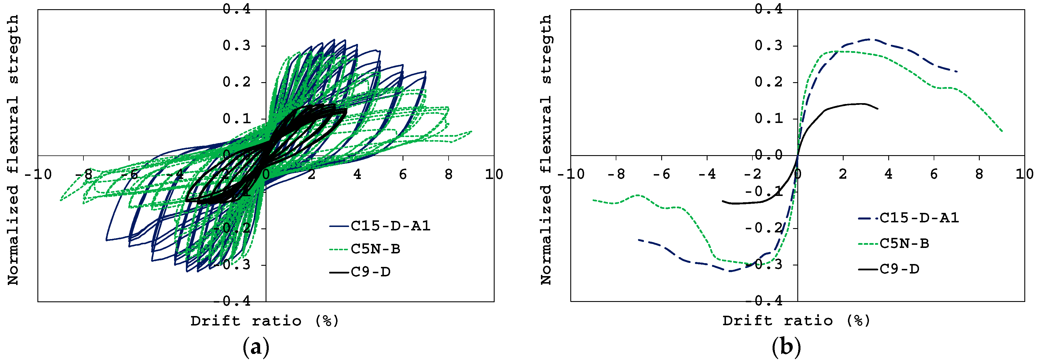
Furthermore, to better examine the performance of the specimen C5N-B subjected to a low value of the axial load, in Figure 12a,b the cyclic response and the corresponding envelope curve are compared with those of the control (unstrengthened) member C9-D and the strengthened column C15-D-A1, tested in the previous experimental campaign [12]. It is worth highlighting that, for a better comparison of the experimental behaviors, both graphs have been represented in normalized terms μ‒δ.
Figure 12. Normalized cyclic (a) and envelope (b) F‒δ curves for specimens subjected to ν = 0.14.
Polymers 07 01499 g012
The plots allow for verifying the beneficial effects of the studied strengthening technique even in presence of low axial load. On average, the flexural strength of the sample C5N-B is about twice that characterizing the control member and only 10% lower than the strength shown by the counterpart C15-D-A1. However, the specimen C5N-B exhibited an abrupt strength degradation in the post-peak phase caused by the rupture of the additional rods arranged in the column, first of which occurred at a displacement of about 70 mm.
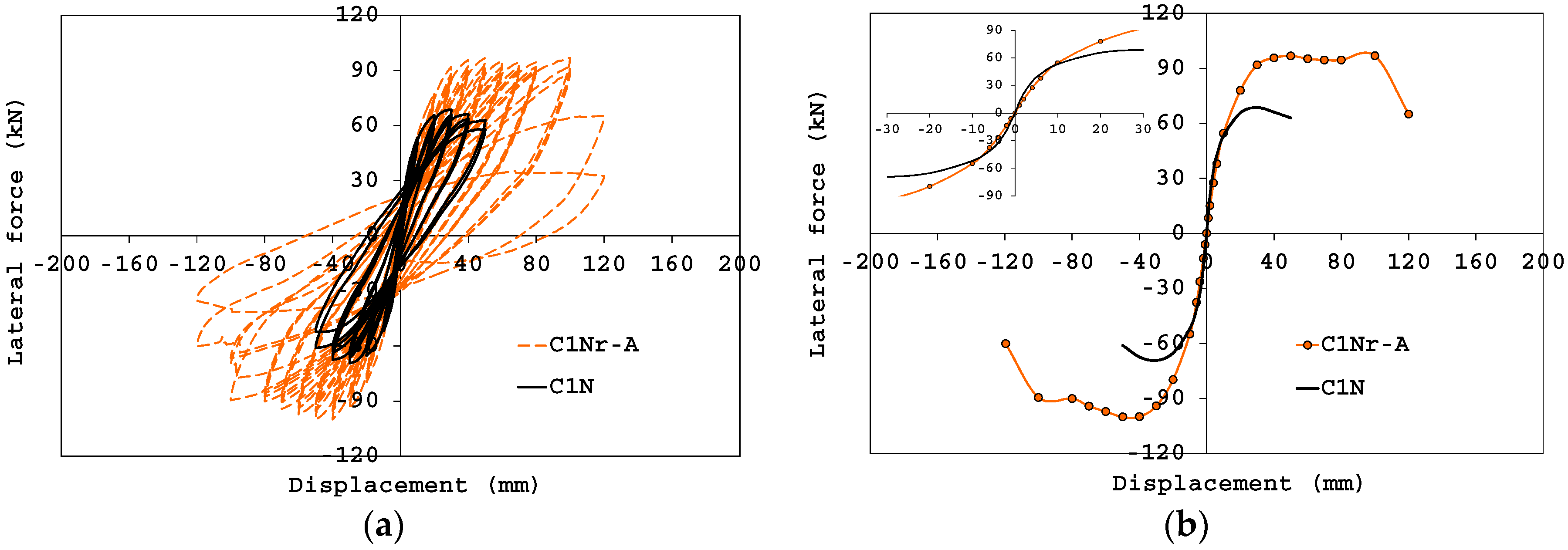
Finally, in Figure 13, the performance of the unstrengthened specimen C1N is compared with that of the repaired one C1Nr-A. The plots allow for verifying the effectiveness of the system “type A” as a repairing technique of damaged columns; as shown, indeed, the application of this system is not only capable of restoring the performance of the original specimen, but also of improving the experimental response in terms of both flexural strength and deformation capacity. By looking at the plot in Figure 13b, it is observed that, except for the reduced initial stiffness (as shown in the F‒Δ enlargement), the member C1Nr-A exhibited an increase of strength and ductility over the counterpart C1N of about 43% and 84%, respectively.
Figure 13. F‒Δ hysteresis curves (a) and envelopes (b): columns C1N and C1Nr-A.
Polymers 07 01499 g013

3.2. Failure Mode

Figure 14, Figure 15 and 
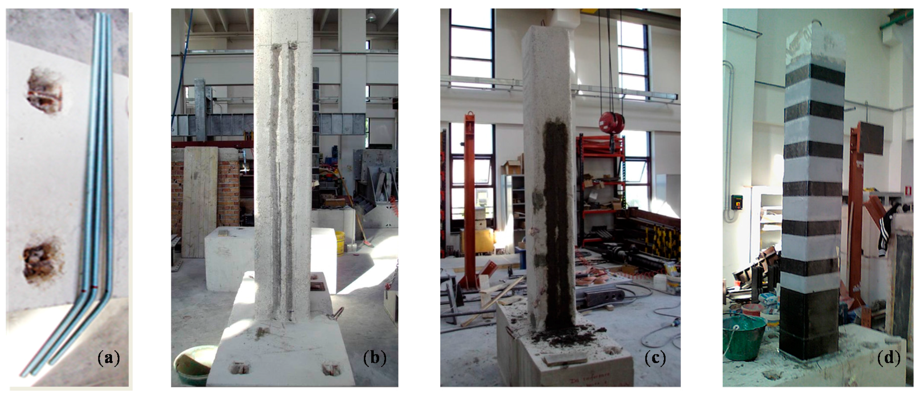
Figure 16 show the crack pattern and failure mode exhibited by test specimens. In particular, as already observed in the previous experimental campaign [
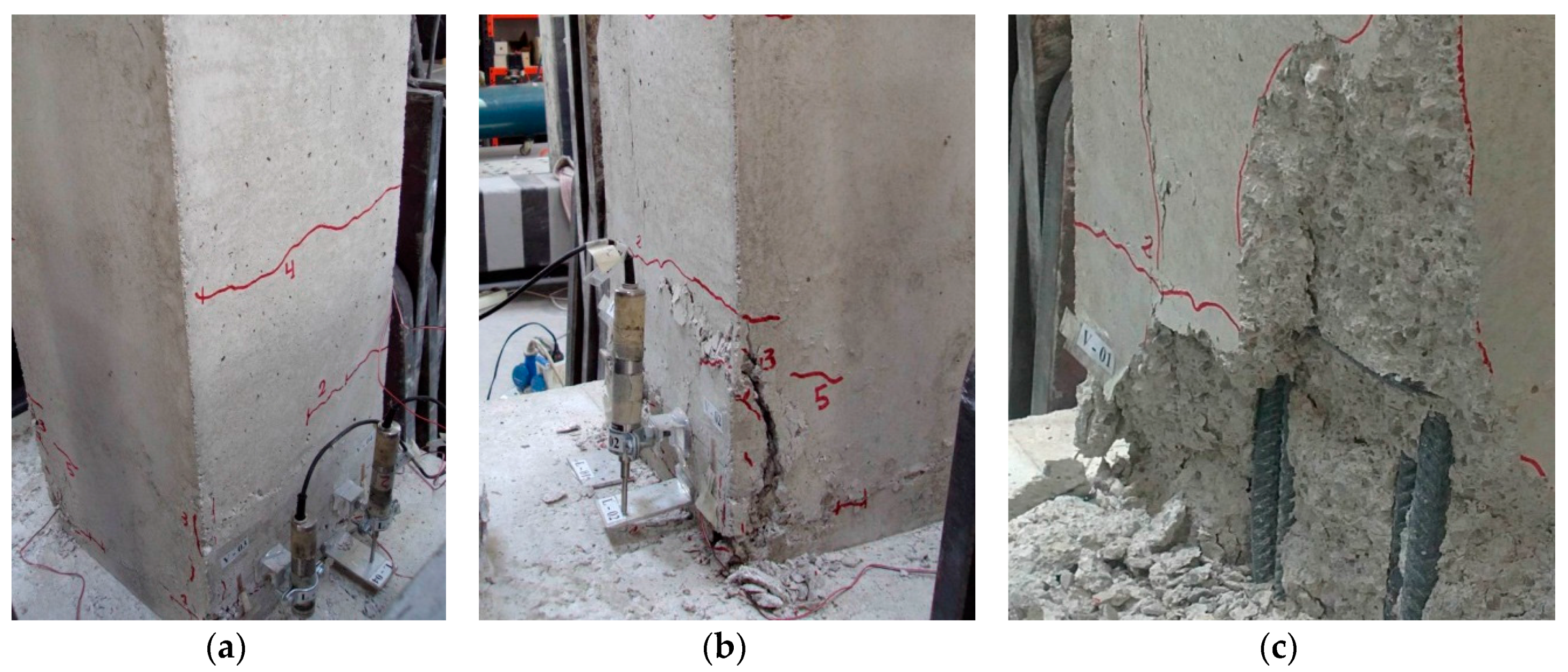
12], the unstrengthened member C1N experienced cracking phenomena and significant damages concentrated in the first 500 mm from the column base (Figure 14). A flexural crack first developed at the column-foundation interface at a displacement value of 20 mm; the width of this crack did not significantly increase during the test since the specimen rapidly achieved the collapse. Other flexural cracks evenly distributed along the member at a distance of about 200 mm, which approximately corresponds to the stirrups spacing (Figure 14a). Lacking adequate confinement, the specimen was rapidly involved by the development of vertical cracks due to the incipient buckling of steel rebars (Figure 14b). Relevant signs of damage and concrete spalling occurred in the first 200 mm from the column base at an imposed displacement of 40 mm (Figure 14c); the test was stopped soon to avoid severe damage of the member since it had to be repaired and re-tested.
Figure 14. Crack pattern: control specimen C1N.
Polymers 07 01499 g014
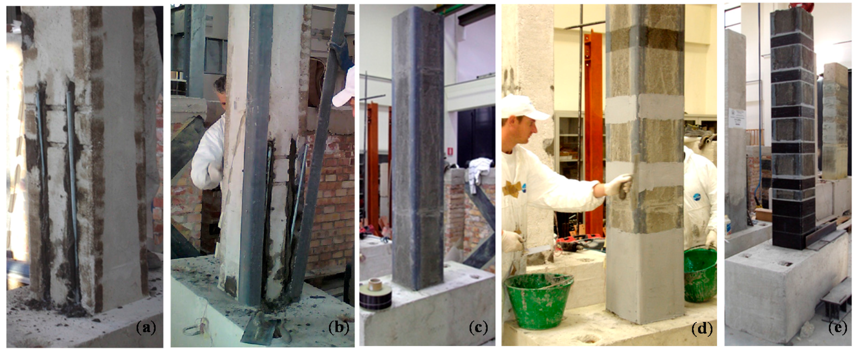
Disregarding the type of strengthening system, the presence of a FRP jacket has contributed to: inhibit the crack opening; delay the buckling of longitudinal rebars. 
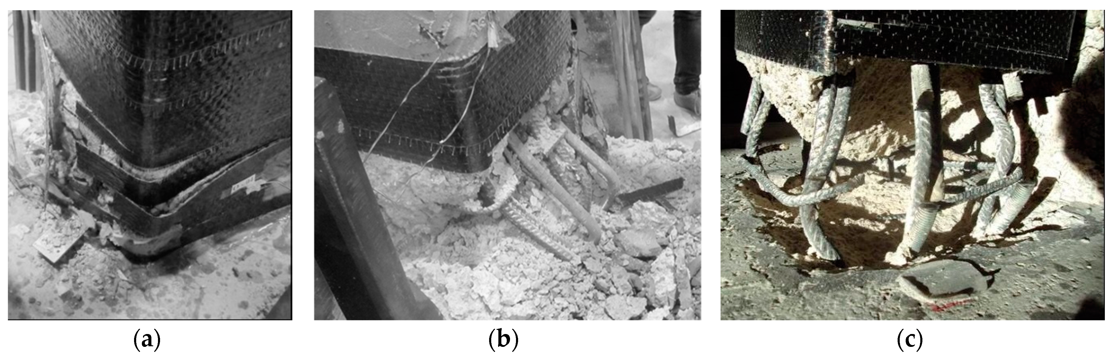
Figure 15a,b illustrate the damage exhibited by strengthened specimens C4N-A, C3N-A and C1Nr-A. As expected, the use of a single FRP layer for the external confinement (test C4N-A) strongly penalized the performance of the column since a first rupture of the sheet prematurely occurred in the first 100 mm from the base (see Figure 15a taken at a displacement of 50 mm). After the FRP system failure, the column rapidly achieved the collapse with the buckling of steel rebars and of the additional rods, stirrups opening and crushing of concrete (Figure 15b). The cyclic behavior of the strengthened specimen significantly improved by doubling the number of FRP layers (test C3N-A); in this case, the FRP rupture occurred in the first 50 mm from the column base only at a displacement value of 120 mm. Figure 15c shows the status of damage at the column base at the end of the test: fracture and buckling of some rebars and rods and stirrups opening were observed.
Figure 15. Damage of specimens strengthened with the system “type A”.
Polymers 07 01499 g015
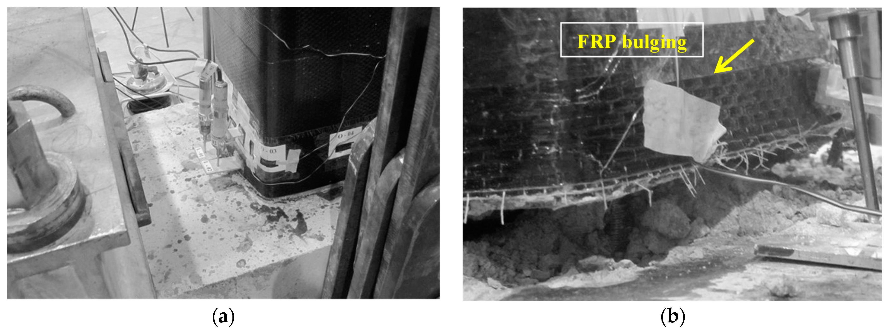
The presence of longitudinal steel profiles (system “type B”) has further inhibited the damage and crack propagation. Independently on the applied axial load ν (0.14 or 0.40) the arrangement of steel profiles avoided the FRP rupture at the base even for high values of the imposed displacement, as shown in Figure 16a. Approaching the end of the test, the FRP exhibited only a bulging in the first 50 mm from the base, whereas inside the wrap the concrete column was severely damaged (Figure 16b). Specimens C5N-B and C2N-B have both experienced the rupture of additional steel rods at column-foundation interface.
Figure 16. Damage of specimens strengthened with the system “type B”.
Polymers 07 01499 g016

3.3. Stiffness Degradation and Energy Dissipation

Based on the experimental results, it was possible to evaluate the mean value of stiffness for the i-th cycle by using the following ratio [17]:
k = | F max , i + | + | F max , i | | s max , i + | + | s max , i |
where F max , i + and F max , i denote the maximum values of the lateral force at the i-th cycle in the push and pull directions, and s max , i + and s max , i are the corresponding displacements.
By normalizing the stiffness of each displacement cycle k with respect to that of the first cycle kI, it was possible to obtain a measure of the stiffness degradation.
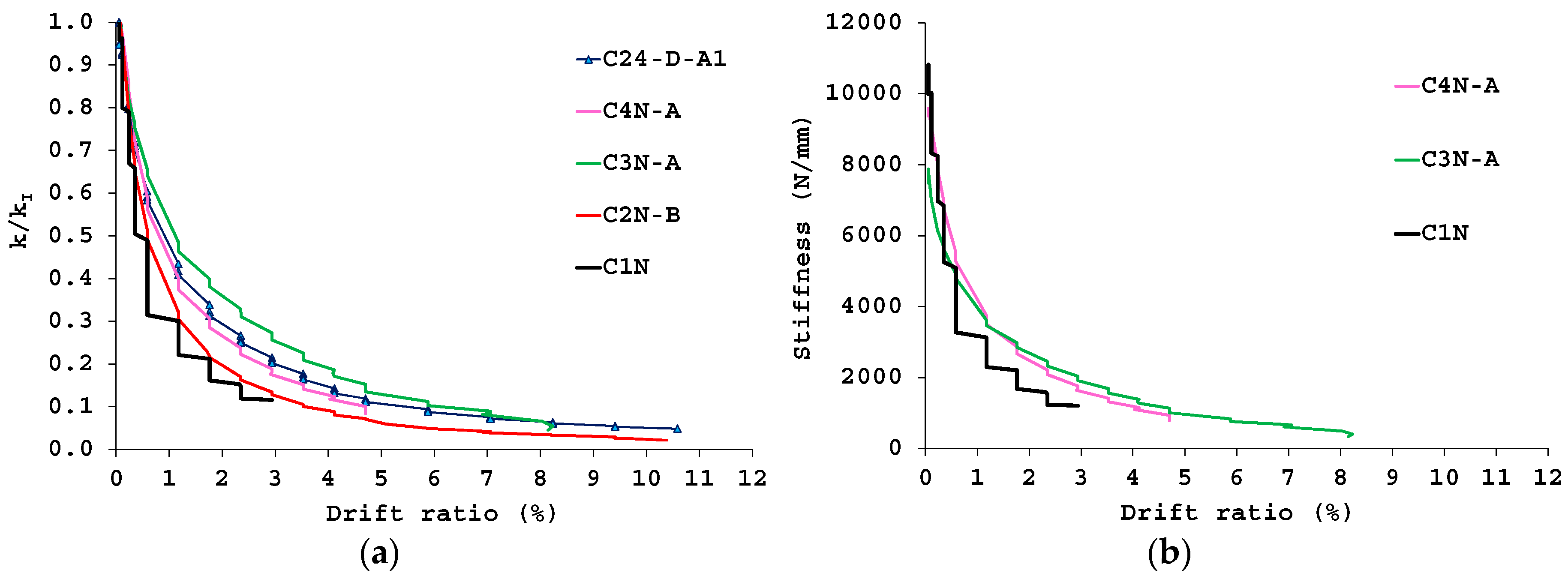
Figure 17a depicts the relationship between the normalized stiffness k/kI and the drift ratio for all the specimens subjected to the higher axial load (ν = 0.40). As expected, lacking the external confinement, the unstrengthened column C1N experienced a more rapid strength degradation with respect to the other specimens. Conversely, it seems that the column C3N-A, although not provided with longitudinal steel profiles, exhibited a strength degradation lower than the counterparts C2N-B and C24-D-A1. This result can be motivated by observing Figure 17b showing that the specimen C3N-A was characterized by an initial stiffness already reduced and significantly lower than that of the control specimen C1N; this evidence might have affected the corresponding strength degradation making it lower than the effective one. However, from Figure 17b it can be observed that also the column C4N-A showed an initial stiffness lower than the unstrengthened specimen. For both columns C3N-A and C4N-A, this reduced initial stiffness can be partly motivated in the installation procedure of the system “type A” which, by requiring the cutting of concrete grooves for introducing the additional steel rods, inevitably induces a pre-damage of the specimens; probably, this pre-damage is not relevant in the case of the specimen C2N-B where the presence of steel angles in some way does not affect the initial stiffness.
Figure 17. Stiffness degradation (a) and stiffness-drift ratio relationship (b) specimens subjected to ν = 0.40.
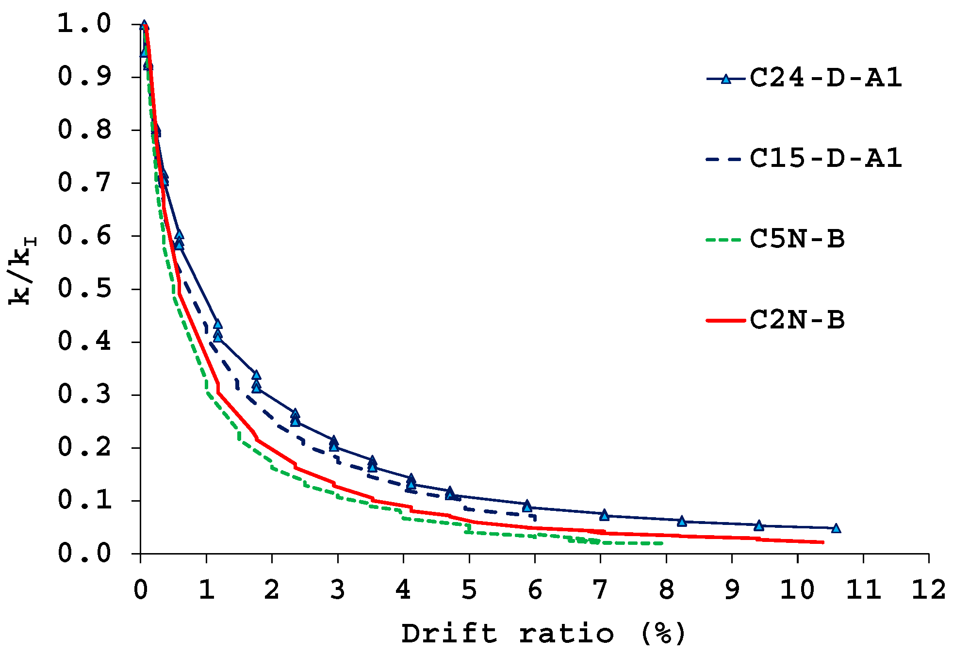
Polymers 07 01499 g017
In Figure 18 the stiffness degradation of columns strengthened with the system: “type B” is compared with that exhibited by the counterparts previously strengthened with the alternative system employing steel profiles at the columns corners (i.e., systems “type A1”). As shown, regardless of the axial load level, the specimens C15-D-A1 (ν = 0.14) and C24-D-A1 (ν = 0.40) exhibited a lower stiffness degradation with respect to the corresponding members C5N-B (ν = 0.14) and C2N-B (ν = 0.40); this result implies that the introduction of internal steel rods in addition to steel profiles and CFRP confinement was less effective than the use of a more complex system like the type A1 one.
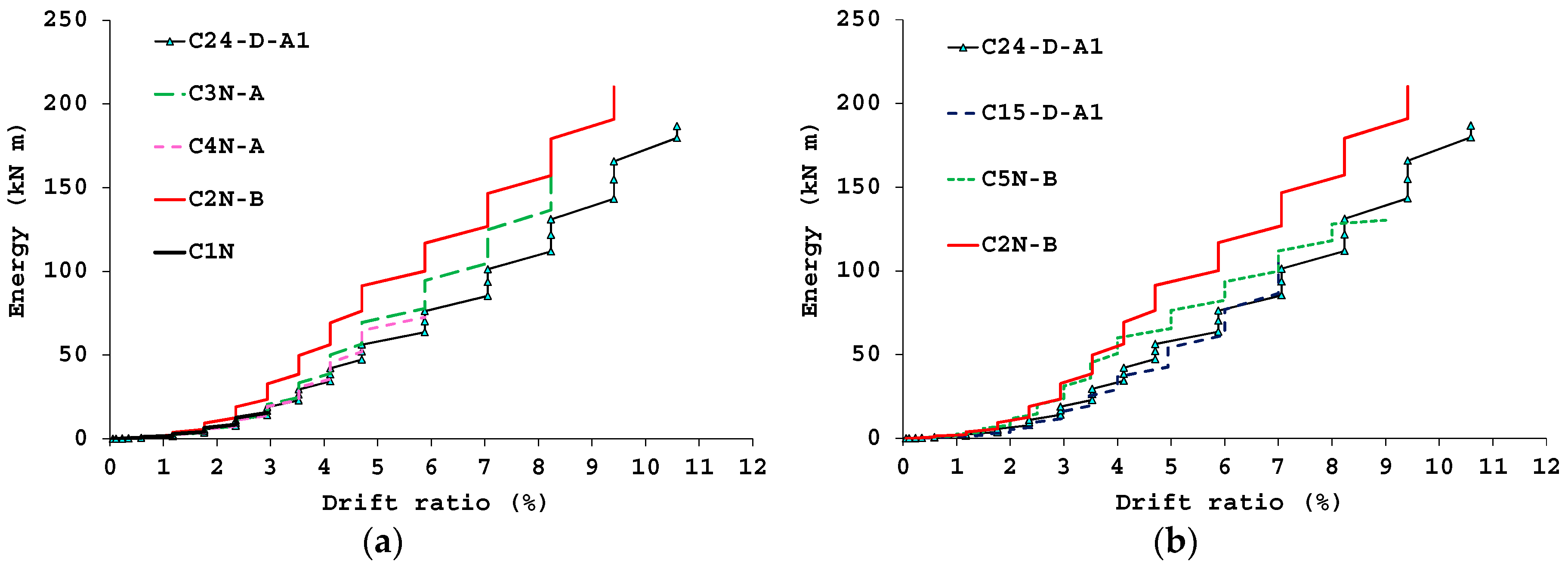
Finally, Figure 19 depicts the relationships between the cumulative dissipated energy (E) and the imposed drift ratio. This energy parameter was calculated from the area under the lateral load-displacement response enclosed within one complete cycle up to the achievement of the conventional collapse for each specimen. In particular, the plot in Figure 19a refers to all the specimens subjected to the higher axial load (ν = 0.40), whereas that in Figure 19b allows for a comparison between systems “type B” and “type A1”.
Figure 18. Stiffness degradation: specimens strengthened with the systems “type B” and “type A1”.
Polymers 07 01499 g018
Figure 19. Energy dissipation: specimens subjected to ν = 0.40 (a) and comparison between systems “type B” and “type A1” (b).
Polymers 07 01499 g019
As already highlighted in [12], from Figure 19a it is observed that the CFRP system produces a significant increase of the cumulative dissipated energy; however, in comparison with the unconfined member C1N, there is no remarkable improvement of the dissipated energy at a given displacement cycle (except for the specimen C2N-B). In the case of the strengthening system “type A”, it is noted that doubling the number of the FRP layers (from one to two) produced only a small increase of the energy performance (compare test C4N-A and C3N-A). Furthermore, disregarding the presence of steel profiles at column corners, the plot in Figure 19a shows that, in terms of dissipated energy, the CFRP strengthening systems “type A” and “type B” are more effective than the previous solution “type A1”, whose width of the hysteresis cycles is strongly affected by the performance of steel profile’s anchoring to the concrete beam/foundation. This experimental evidence is also confirmed by observing the plot in Figure 19b where, regardless of the applied axial load level, the energy dissipated by columns strengthened with the system “type B” is significantly greater than that computed for the counterparts C15-D-A1 and C24-D-A1.

3.4. Strain Values

As already mentioned, measurements of the hoop FRP strain were recorded during tests by eight strain gauges (labelled H1, H2 and H8) arranged on the FRP jacket at a distance of about 100 mm from the column base. In addition, in the case of the strengthening system “type B”, two couples of strain gauges (labelled V1–V2, and V3–V4) were placed on the respective steel L-shape profiles (at about 600 mm from the column base) to monitor the strain distribution during tests.
Figure 20 shows for the strengthened members the envelopes of the FRP transverse strains (εh) plotted under both positive (push) and negative (pull) directions of the imposed displacement Δ; such plots allow for obtaining a qualitative trend of the strains achieved by the FRP jacket. In particular, the strain diagrams refer to the maximum values recorded at the first of the three cycles performed at each level of the imposed displacement, up to the end of the test (when the measures were available); negative and positive values of εh indicate compressive and tensile strains of the FRP jacket, respectively.
Under Δ = 0, i.e., at the origin of the ε–Δ axes, the plots report the small values of the FRP strains exhibited after the application of pure axial load on the columns.
Observing the plots in Figure 20, it is highlighted that, disregarding the type of strengthening system, the maximum tensile strains never attained the ultimate FRP strain value indicated by the supplier (εf,u = 8‰); in particular, except for measures provided some strain gauges, the higher strains were below the 2‰–2.4‰ threshold (which is only 1/4–1/3 of εf,u).
By comparing the plots in Figure 20a,b it is observed that, at a given level of the imposed displacement, the tensile strains recorded in the case of the test C4N-A were generally higher than those measured by doubling the number of layers for the continuous FRP jacket (test C3N-A), with maximum values recorded by the strain gauge H2.
The FRP strains typically increase in the case of the strengthening system “type B” (see test C2N-B in Figure 20c), where the values recorded by strain gauges H6 and H8 are well over the 2‰ threshold. Conversely, reduced values were, on average, recorded for the specimen C5N-B (Figure 20d) where a reduced efficacy of the FRP jacket is obtained under lower axial load levels (ν = 0.14).
Figure 20. FRP strains: tests C3N-A (a); C4N-A (b); C2N-B (c); and C5N-B (d).
Polymers 07 01499 g020
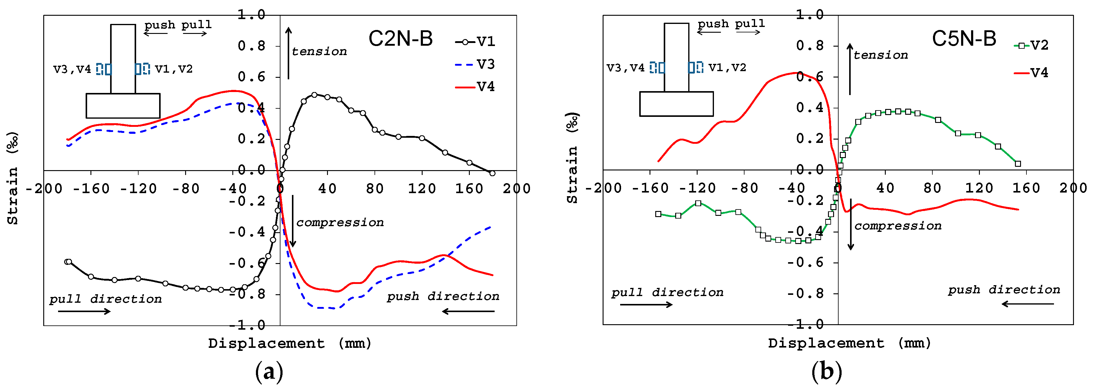
Finally, by focusing on the strengthening system “type B”, Figure 21 shows the envelopes of the longitudinal strains (εv) recorded by the couples of strain gauges V1, V2 and V3, V4 placed on the L-shape steel profiles (the measures were not always available); negative and positive values of εv indicate compressive and tensile strains in the profiles, respectively. A rather symmetric response of the strains in the push and pull directions is observed from the plots, with maximum values recorded under the higher axial load (test C2N-B in Figure 21a); however, it is highlighted that such strains were always below 0.9‰, thus implying that the use of steel profiles mainly contributes to improving the external confinement of the columns rather than significantly increasing their flexural strength.
Figure 21. Strains on the L-shape steel profiles: tests C2N-B (a) and C5N-B (b).
Polymers 07 01499 g021

4. Conclusions

In this paper, results from cyclic tests on RC columns strengthened with novel CFRP systems have been presented and compared with those of companion specimens tested in a previous experimental campaign. In particular, two strengthening solutions were investigated herein, namely “type A” and “type B”. The first solution (“type A”) consisted of placing four steel threaded rods inside concrete grooves which were adhesively bonded into the foundation for a length of about 250 mm; then, the strengthening was completed by external CFRP confinement. The second solution (“type B”), instead, differed from the first one for the additional use of L-shape steel profiles at the column corners before applying the CFRP confinement.
From the performed tests it has been highlighted that in presence of high axial load (ν = 0.40), the strengthened specimens have exhibited increases of strength ranging from 48% to 60% with respect to the control sample. In the case of samples strengthened by the system “type A”, a delayed FRP failure has been noticed by doubling the number of FRP layers, and 30% greater displacements at collapse were measured. The addition of steel profiles at column corners (system “type B”) avoided the failure of the FRP wrap itself and delayed the crushing of the concrete; indeed, beyond the conventional collapse, the specimens were still capable of undergoing significant lateral displacements.
Furthermore, it has been shown that the columns strengthened with the system “type B” have provided increases of flexural strength and ductility slightly lower than those obtained through the layout “type A1”, examined in the previous experimental campaign. However, it is worth noting that this beneficial effect is offset by the need of time consuming and labor-intensive operations to provide a proper installation of the anchor system of steel profiles; on site, such installation is even more difficult when the anchoring of column’s steel profiles is made into a beam member rather than a concrete foundation. Finally, even though a greater stiffness degradation was computed, in terms of dissipated energy, the CFRP strengthening systems “type A” and “type B” were more effective than the previous solution “type A1”, whose width of the hysteresis cycles is strongly affected by the performance of steel profile’s anchoring to the concrete beam/foundation.

Acknowledgements

The Authors gratefully acknowledge Interbau Srl (Milan, Italy) for the technical and financial support to the experimental program.

Author Contributions

Annalisa Napoli and Roberto Realfonzo have evenly contributed to all the steps needed to produce this article, from conceiving, designing and performing tests, to analyzing the experimental results and writing the paper.

Conflicts of Interest

The authors declare no conflict of interest.

References

  1. American Concrete Institute (ACI) Committee 440. Guide for the Design and Construction of Externally Bonded FRP Systems for Strengthening Concrete Structures; ACI 440.2R-08; Farmington Hills, MI, USA, 2008. [Google Scholar]
  2. Fédération internationale du béton (fib). Externally Bonded FRP Reinforcement for RC Structures; Bulletin No. 14; fib Bulletin: Lausanne, Switzerland, 2001. [Google Scholar]
  3. National Research Council (CNR). Guide for the Design and Construction of Externally Bonded FRP Systems for Strengthening Existing Structures (Materials, RC and PC Structures, Masonry Structures); CNR-DT200; Rome, Italy, 2004. [Google Scholar]
  4. Realfonzo, R.; Napoli, A. Concrete confined by FRP systems: Confinement efficiency and design strength models. Compos. B Eng. 2011, 42, 736–755. [Google Scholar] [CrossRef]
  5. Realfonzo, R.; Napoli, A. Confining concrete members with FRP systems: Predictive vs. design strain models. Compos. Struct. 2013, 104, 304–319. [Google Scholar] [CrossRef]
  6. Iacobucci, R.D.; Sheikh, S.A.; Bayrak, O. Retrofit of square concrete columns with carbon fiber reinforced polymer for seismic resistance. ACI Struct. J. 2003, 100, 785–794. [Google Scholar]
  7. Harries, K.A.; Ricle, J.R.; Pessiki, S.; Sause, R. Seismic retrofit of lap splices in nonductile square columns using carbon fiber-reinforced jackets. ACI Struct. J. 2006, 103, 874–884. [Google Scholar]
  8. Harajli, M.H.; Dagher, F. Seismic strengthening of bond-critical regions in rectangular reinforced concrete columns using fiber-reinforced polymer wraps. ACI Struct. J. 2008, 105, 68–77. [Google Scholar]
  9. Rutledge, S.; Seracino, R.; Kowalsky, M.; Witt, M. FRP repair of damaged large-scale circular reinforced concrete columns. In Proceedings of the 15th World Conference on Earthquake Engineering (WCEE), Lisboa, Portugal, 24–28 September 2012.
  10. Bousias, S.N.; Fardis, M.N.; Biskinis, D. Retrofit of RC columns with deficient lap splices. In Proceedings of Fib Symposium “Keep Concrete Attractive”, Budapest, Hungary, 23–25 May 2005.
  11. Bournas, D.A.; Lontou, P.V.; Papanicolaou, C.G.; Triantafillou, T.C. Textile-reinforced mortar versus fiber-reinforced polymer confinement in reinforced concrete columns. ACI Struct. J. 2007, 104, 740–748. [Google Scholar]
  12. Realfonzo, R.; Napoli, A. Cyclic behavior of RC columns strengthened by FRP and steel devices. J. Struct. Eng. 2009, 135, 1164–1176. [Google Scholar] [CrossRef]
  13. Realfonzo, R.; Napoli, A. Results from cyclic tests on high aspect ratio RC columns strengthened with FRP systems. Constr. Build. Mater. 2012, 37, 606–620. [Google Scholar] [CrossRef]
  14. Nuove Norme Tecniche per le Costruzioni (NTC); Consiglio Superiore dei Lavori Pubblici: Rome, Italy, 2008. (In Italian)
  15. Interbau Srl. Available online: http://www.interbau-srl.it (accessed on 30 June 2015).
  16. Sikadur®30 Adhesive for bonding reinforcement. Available online: http://www.sika.com (accessed on 30 June 2015).
  17. Mayes, R.L.; Clough, R.W. State of the Art in Seismic Shear Strength of Masonry—An Evaluation and Review; EERC Report: Berkeley, CA, USA, 1975. [Google Scholar]

