Morphological and Tribological Properties of PMMA/Halloysite Nanocomposites

 , , , , ,
Abstract
:1. Introduction
2. Materials and Methods
2.1. Materials
2.2. Preparation of Nanocomposites and Samples
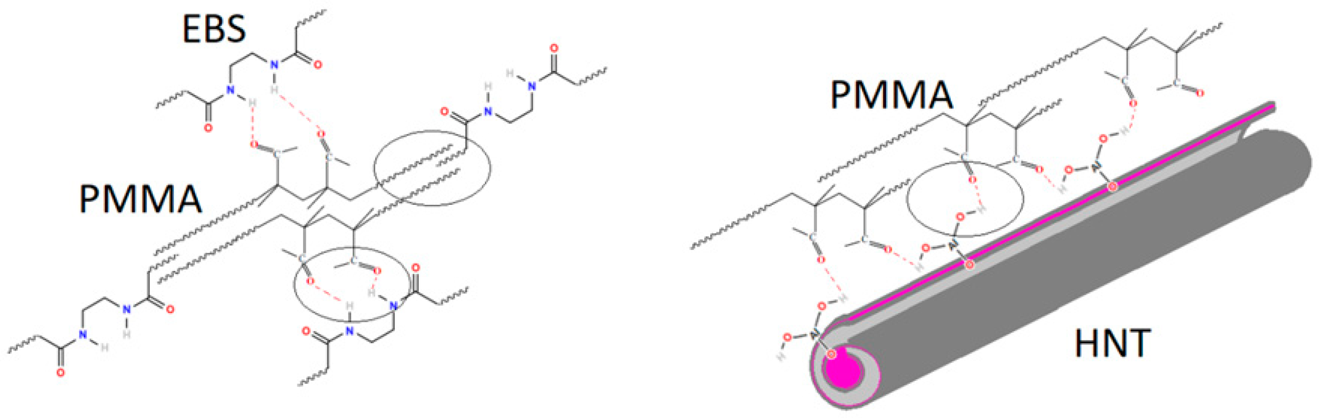
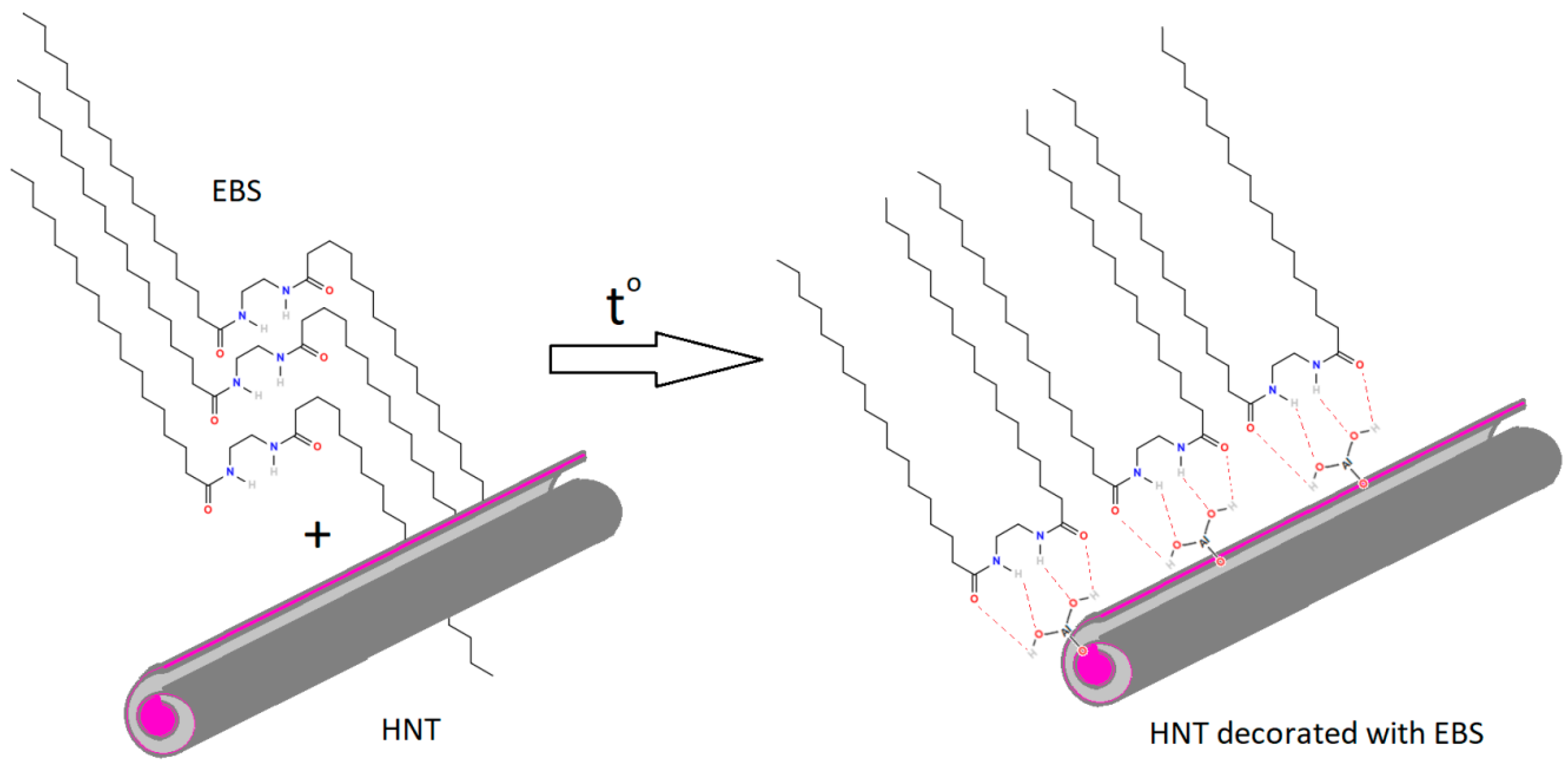
2.2.1. Modification of HNT with EBS
2.2.2. Obtaining of PMMA/HNT Nanocomposites
2.3. Characterization
2.3.1. Thermal Analysis
2.3.2. Structure/Morphology
XRD
FTIR
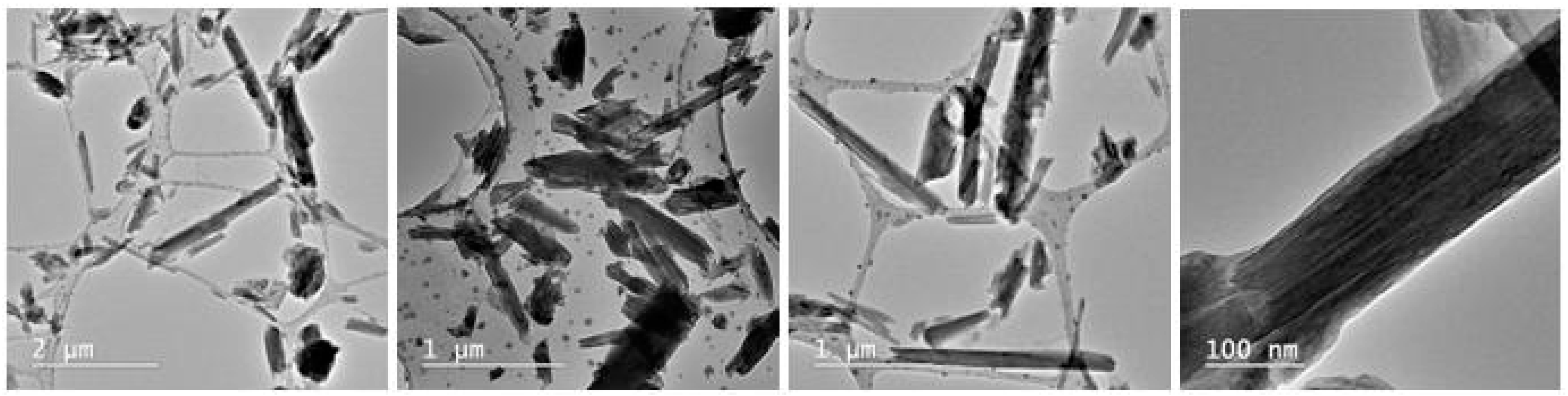
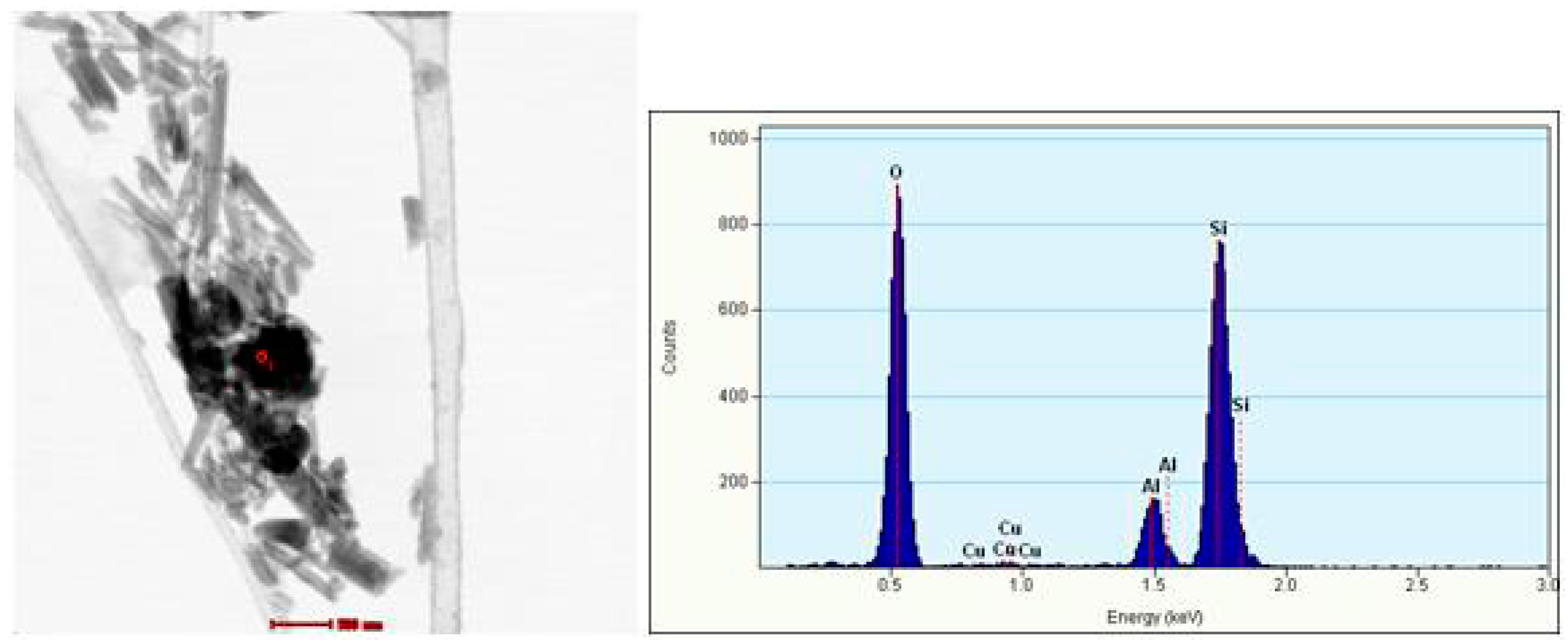
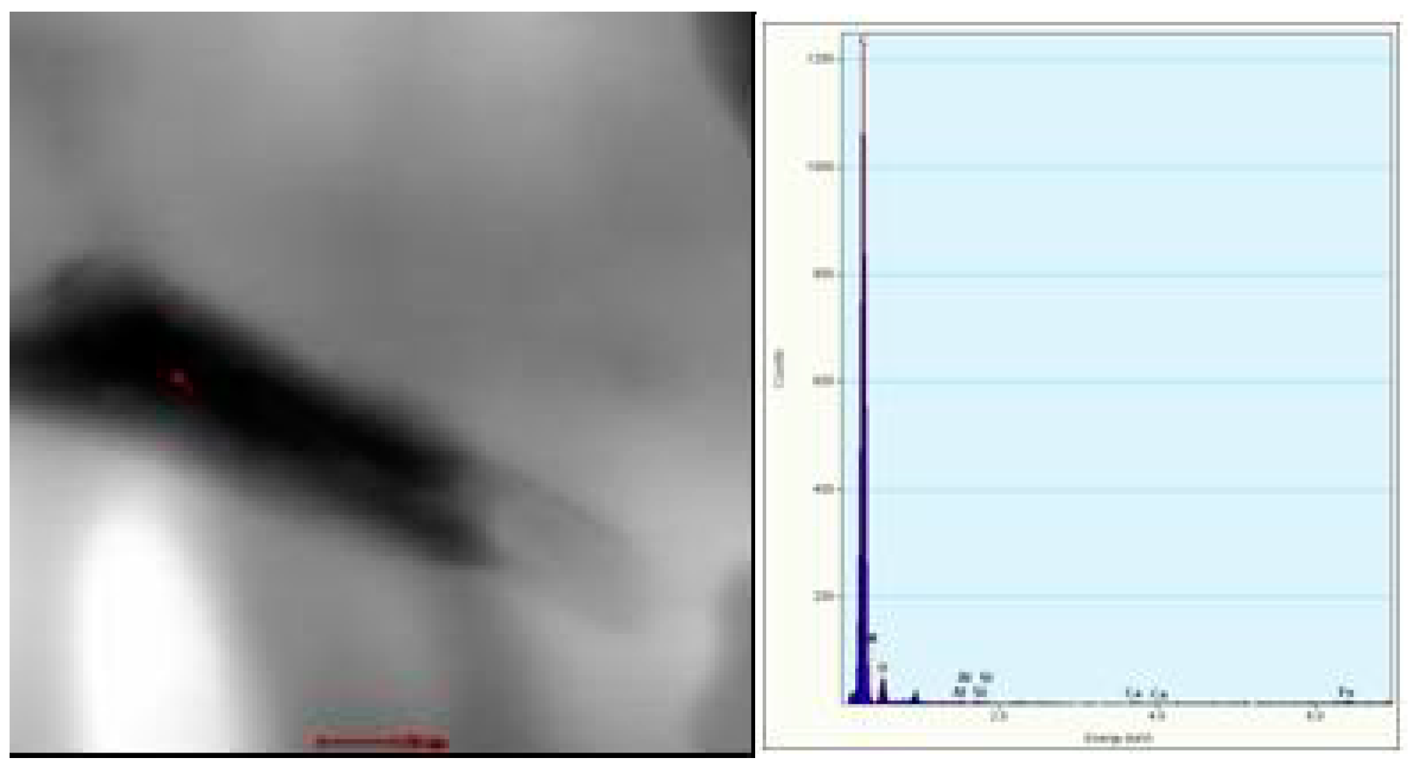
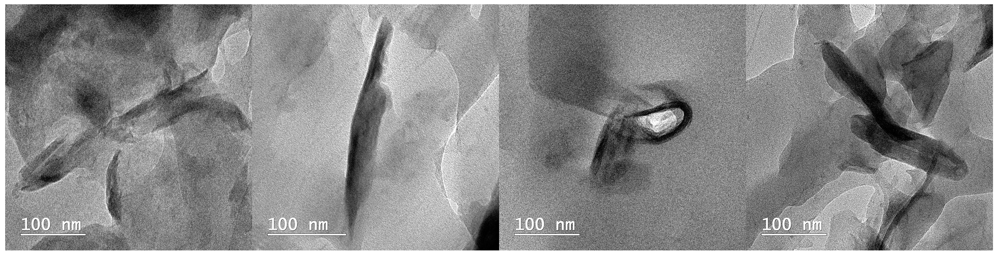
TEM
2.3.3. Mechanical Properties
Conventional Tensile and Impact Testing
Nanomechanical Characterization
3. Results and Discussion
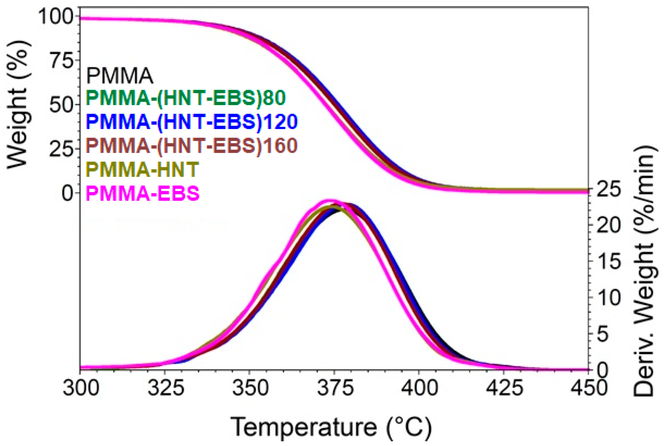
3.1. Thermal Properties
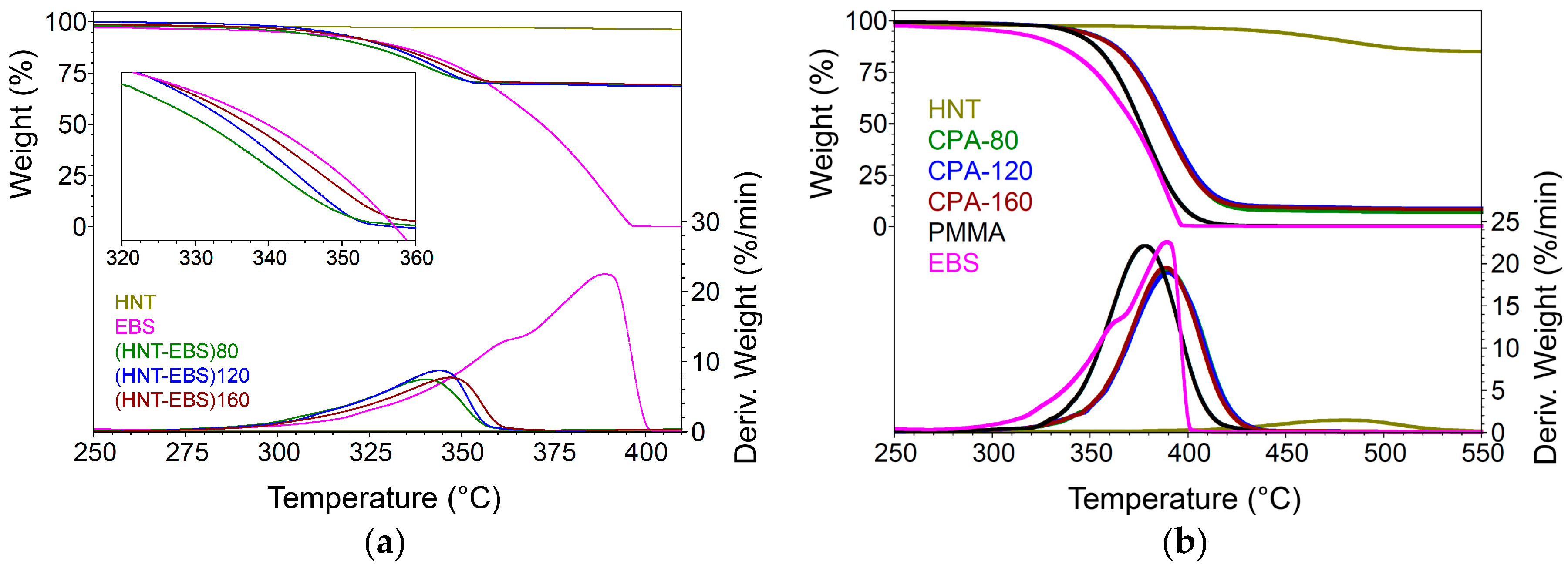
3.1.1. TGA
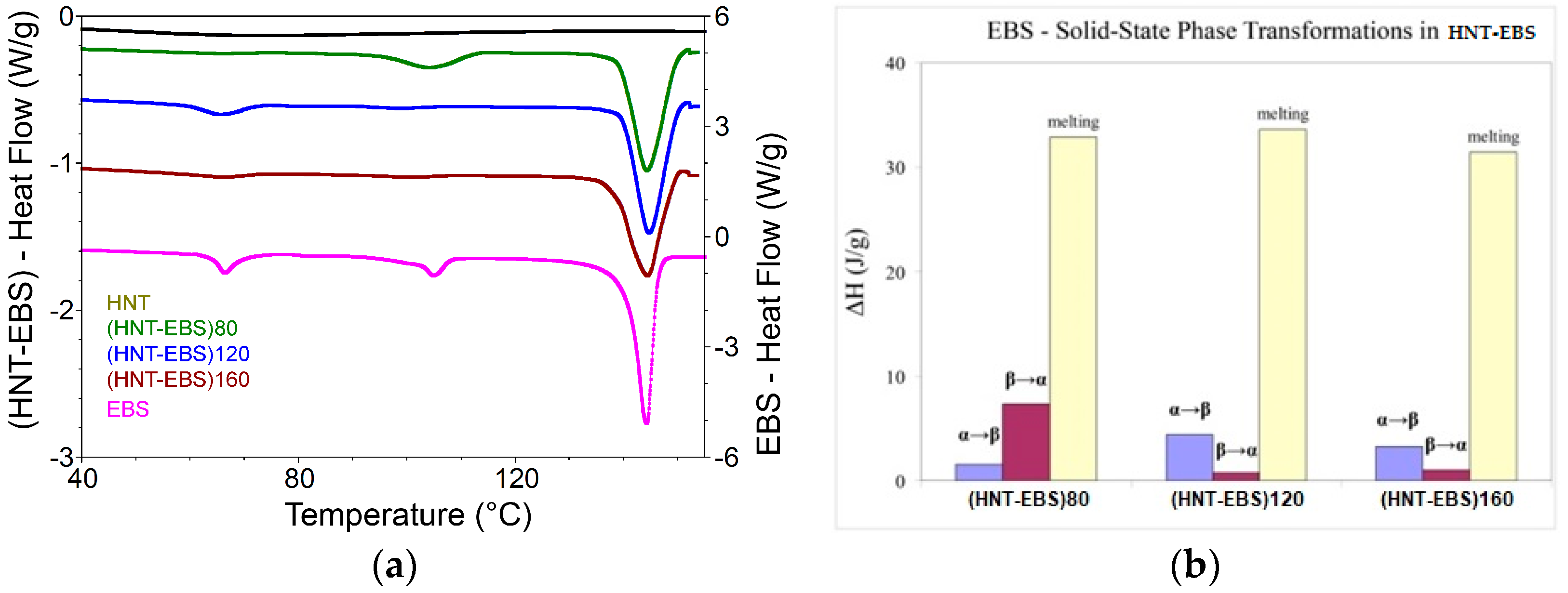
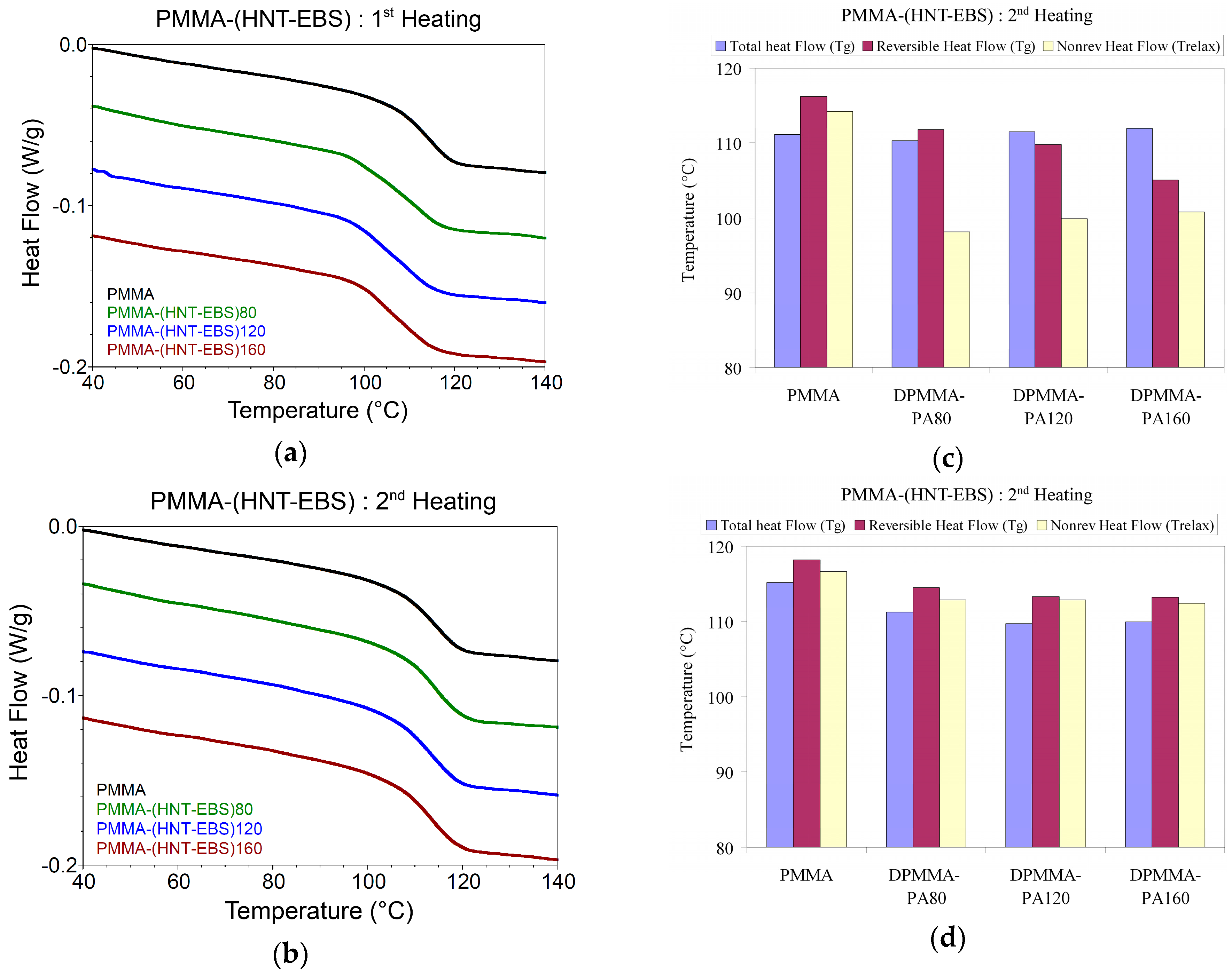
3.1.2. DSC
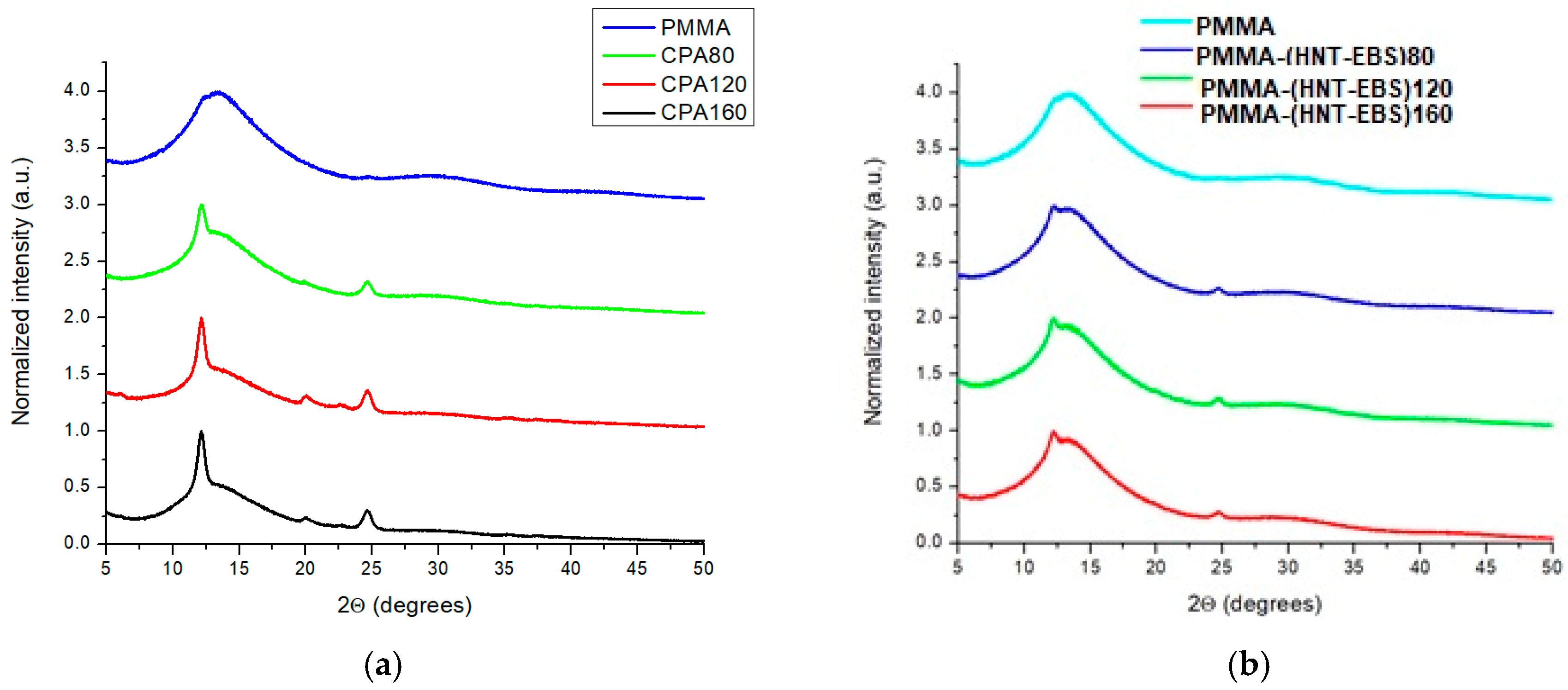
3.2. Structure/Morphology
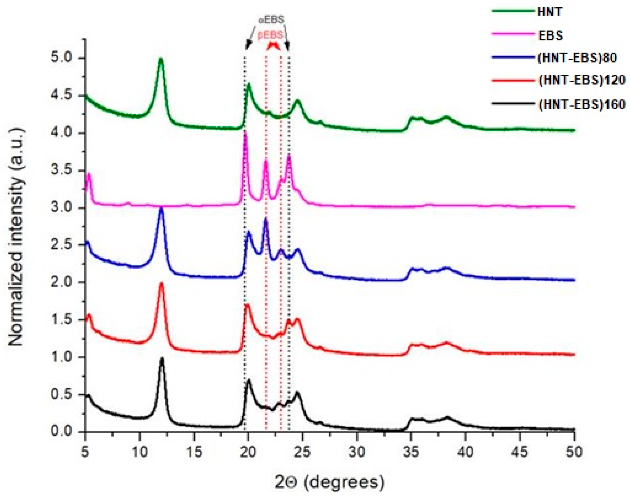
3.2.1. XRD
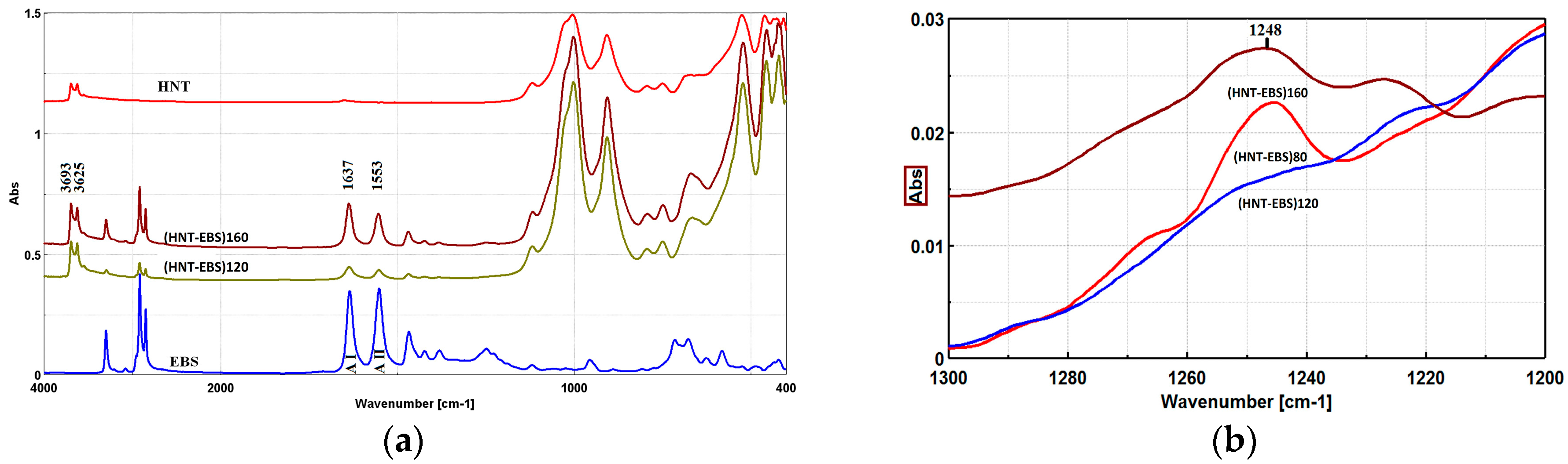
3.2.2. FTIR
3.2.3. TEM
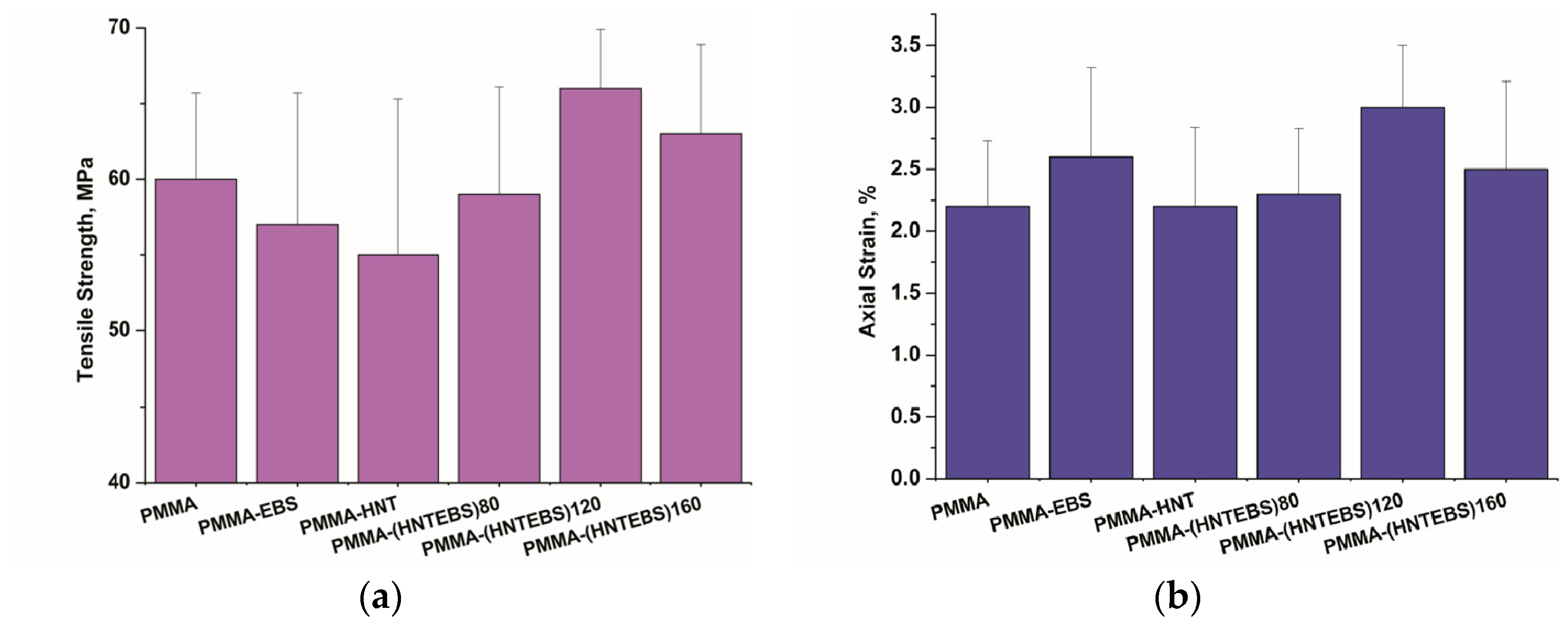
3.3. Mechanical Properties
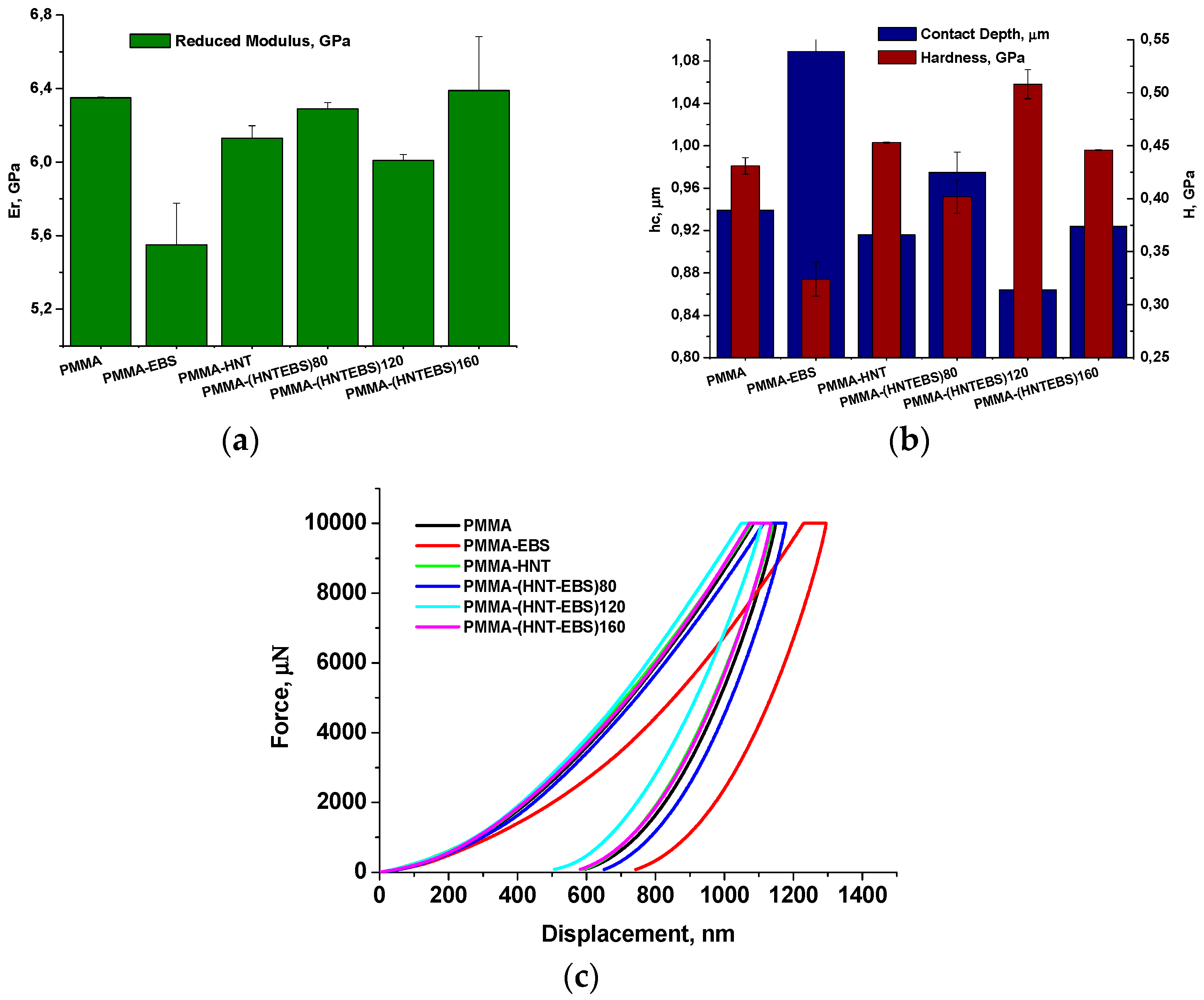
3.4. Nanomechanical Properties
3.4.1. Nanoindentation Test Results
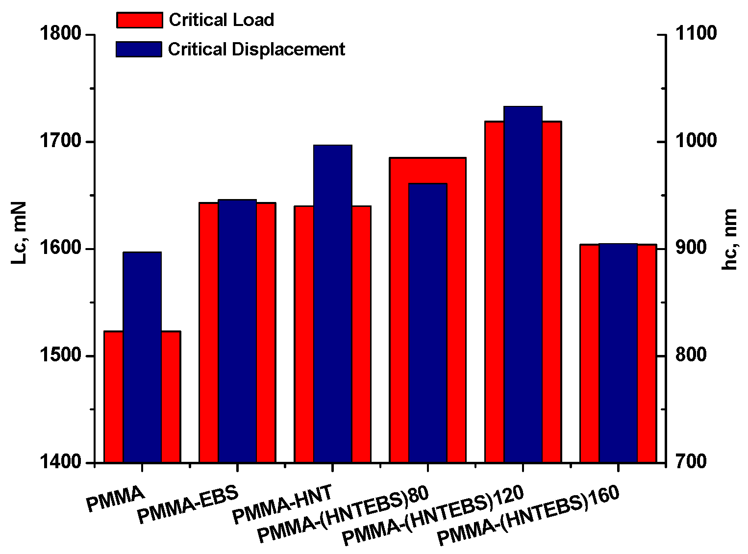
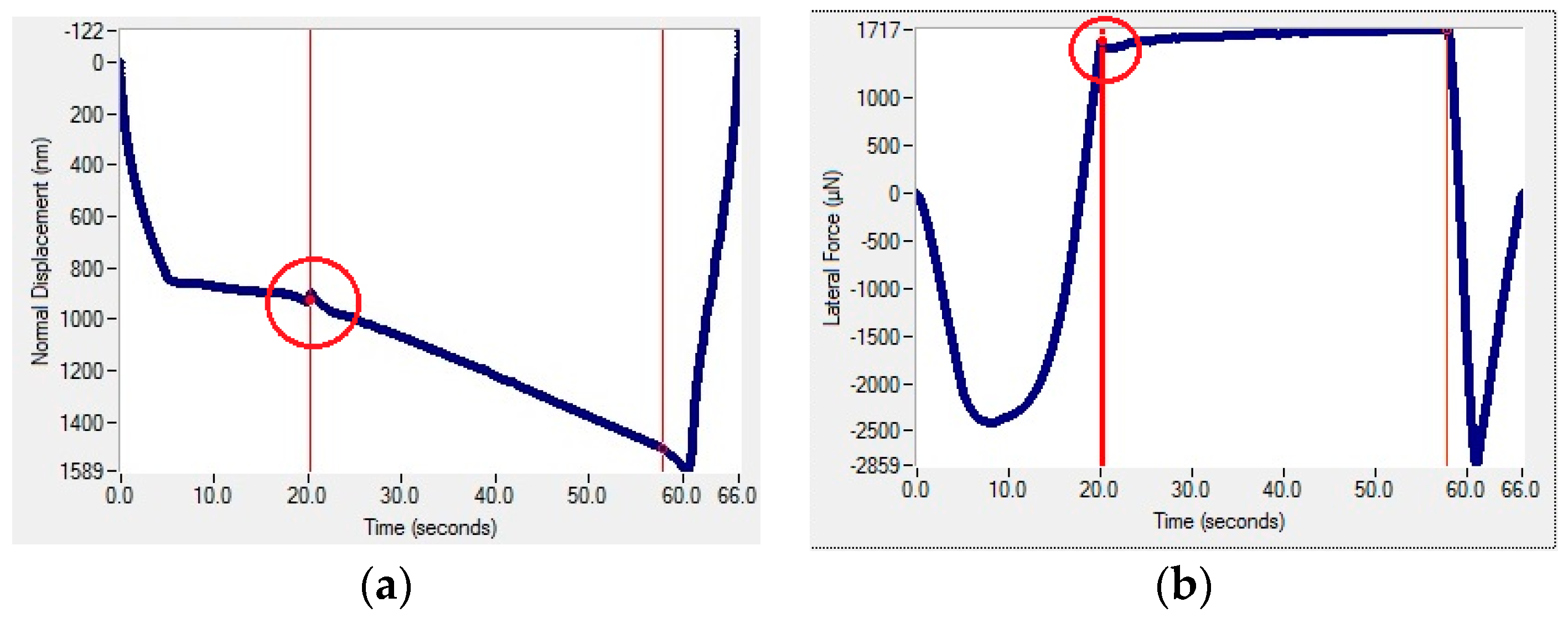
3.4.2. Nanoscratch Test Results
4. Conclusions
Supplementary Materials
Author Contributions
Funding
Acknowledgments
Conflicts of Interest
References
- Markarian, J. Additives improve scratch resistance in automotive applications. Plast. Addit. Compd. 2009, 11, 10–15. [Google Scholar] [CrossRef]
- Jiang, H.; Browning, R.; Sue, H.-J. Understanding of scratch-induced damage mechanisms in polymers. Polymer 2009, 50, 4056–4065. [Google Scholar] [CrossRef]
- Dasari, A.; Rohrmann, J.; Misra, R.D.K. Micro- and Nanoscale Evaluation of Scratch Damage in Poly(propylene)s. Macromol. Mater. Eng. 2002, 287, 889–903. [Google Scholar] [CrossRef]
- An, J.; Kang, B.-H.; Choi, B.-H.; Kim, H.-J. Observation and evaluation of scratch characteristics of injection-molded poly(methyl methacrylate) toughened by acrylic rubbers. Tribol. Int. 2014, 77, 32–42. [Google Scholar] [CrossRef]
- Ali, U.; Abd Karim, K.J.B.; Buang, N.A. A Review of the Properties and Applications of Poly(Methyl Methacrylate) (PMMA). Polym. Rev. 2015, 55, 678–705. [Google Scholar] [CrossRef]
- Pal, K. Effect of different nanofillers on mechanical and dynamic behavior of PMMA based nanocomposites. Compos. Commun. 2016, 1, 25–28. [Google Scholar] [CrossRef]
- Kim, B.-C.; Kim, H.-J.; Choi, B.-H.; Lee, H.-S. An experimental study of the scratch properties of poly(methyl methacrylate) as a function of the concentration of added slip agent. Tribol. Int. 2011, 44, 2035–2041. [Google Scholar] [CrossRef]
- Lehmann, K.; Tomuschat, P. New additive technology provides scratch resistance. Plast. Addit. Compd. 2008, 10, 1–4. [Google Scholar] [CrossRef]
- Pelletier, H.; Durier, A.-L.; Gauthier, C.; Schirrer, R. Viscoelastic and elastic– plastic behaviors of amorphous polymeric surfaces during scratch. Tribol. Int. 2008, 41, 975–984. [Google Scholar] [CrossRef]
- Moghbelli, E.; Browning, R.L.; Boo, W.-J.; Hahn, S.F.; Feick, L.J.E.; Sue, H.-J. Effects of molecular weight and thermal history on scratch behavior of polypropylene thin sheets. Tribol. Int. 2008, 41, 425–433. [Google Scholar] [CrossRef]
- Xiang, C.; Sue, H.-J.; Chu, J.; Masuda, K. Roles of Additives in Scratch Resistance of High Crystallinity Polypropylene Copolymers. Polym. Eng. Sci. 2001, 41, 23–31. [Google Scholar] [CrossRef]
- Chu, J.; Xiang, C.; Sue, H.-J.; Damon Hollis, R. Resistance of Mineral-Filled Polypropylene Materials. Polym. Eng. Sci. 2000, 40, 944–955. [Google Scholar] [CrossRef]
- Browning, R.; Lim, G.T.; Moyse, A.; Sun, L.; Sue, H.-J. Effects of Slip Agent and Talc Surface-Treatment on the Scratch Behavior of Thermoplastic Olefins. Polym. Eng. Sci. 2006, 46, 601–608. [Google Scholar] [CrossRef]
- Mansha, M.; Gauthier, C.; Gerard, P.; Schirrer, R. The effect of plasticization by fatty acid amides on the scratch resistance of PMMA. Wear 2011, 271, 671–679. [Google Scholar] [CrossRef]
- Alvarado-Rivera, J.; Munoz-Saldana, J.; Ramırez-Bon, R. Nanoindentation testing of SiO2-PMMA hybrid films on acrylic substrates with variable coupling agent content. J. Sol-Gel Sci. Technol. 2010, 54, 312–318. [Google Scholar] [CrossRef]
- Chakraborty, H.; Sinha, A.; Mukherjee, N.; Ray, D.; Chattopadhyay, P.P. A study on nanoindentation and tribological behaviour of multifunctional ZnO/PMMA nanocomposite. Mater. Lett. 2013, 93, 137–140. [Google Scholar] [CrossRef]
- Akinci, A.; Sen, S.; Sen, U. Friction and wear behavior of zirconium oxide reinforced PMMA composites. Compos. Part B-Eng. 2014, 56, 42–47. [Google Scholar] [CrossRef]
- Dasari, A.; Yu, Z.-Z.; Mai, Y.-W. Nanoscratching of nylon 66-based ternary nanocomposites. Acta Mater. 2007, 55, 635–646. [Google Scholar] [CrossRef]
- Bojda, J.; Piorkowska, E.; Murariu, M.; Bonnaud, L.; Dubois, P. The effect of halloysite nanotubes and N,N’-ethylenebis (stearamide) on the properties of polylactide nanocomposites with amorphous matrix. Polym. Test. 2017, 61, 35–45. [Google Scholar]
- Abdallah, R.M. Evaluation of polymethyl methacrylate resin mechanical properties with incorporated halloysite nanotubes. J. Adv. Prosthodont. 2016, 8, 167–171. [Google Scholar] [CrossRef] [PubMed]
- Deepak, R.; Agrawal, Y.K. Study of nanocomposites with emphasis to halloysite nanotubes. Rev. Adv. Mater. Sci. 2012, 32, 149–157. [Google Scholar]
- Yuan, P.; Southon, P.D.; Liu, Z.; Green, M.E.R.; Hook, J.M.; Antill, S.J.; Kepert, C.J. Functionalization of Halloysite Clay Nanotubes by Grafting with γ-Aminopropyltriethoxysilane. J. Phys. Chem. C 2008, 112, 15742–15751. [Google Scholar] [CrossRef]
- Prashantha, K.; Lecouvet, B.; Sclavons, M.; Lacrampe, M.F.; Krawczak, P. Poly(lactic acid)/halloysite nanotubes nanocomposites: Structure, thermal, and mechanical properties as a function of halloysite treatment. J. Appl. Polym. Sci. 2013, 128, 1895–1903. [Google Scholar] [CrossRef]
- Krishnaiah, P.; Ratnam, C.T.; Manickam, S. Development of silane grafted halloysite nanotube reinforced polylactide nanocomposites for the enhancement of mechanical, thermal and dynamic-mechanical properties. Appl. Clay Sci. 2017, 135, 583–595. [Google Scholar] [CrossRef]
- Chow, W.S.; Lim, S.R. Effect of N,N’-Ethylenebis(stearamide) on the Properties of Polyethylene terephthalate)/Organomontmorillonite Nanocomposite. Polym.-Plast. Technol. Eng. 2013, 52, 626–633. [Google Scholar] [CrossRef]
- Pluta, M.; Bojda, J.; Piorkowska, E.; Murariu, M.; Bonnaud, L.; Dubois, P. The effect of halloysite nanotubes and N,N’-ethylene bis(stearamide) on morphology and properties of polylactide nanocomposites with crystalline matrix. Polym. Test. 2017, 64, 83–91. [Google Scholar] [CrossRef]
- Wei, W.; Abdullayev, E.; Hollister, A.; Mills, D.; Lvov, Y.M. Clay Nanotube/Poly(methyl methacrylate) Bone Cement Composites with Sustained Antibiotic Release. Macromol. Mater. Eng. 2012, 297, 645–653. [Google Scholar] [CrossRef]
- Jardret, V.; Morel, P. Viscoelastic effects on the scratch resistance of polymers: Relationship between mechanical properties and scratch properties at various temperatures. Prog. Org. Coat. 2003, 48, 322–331. [Google Scholar] [CrossRef]
- Zsirka, B.; Horváth, E.; Szabób, P.; Juzsakova, T.; Szilágyi, R.K.; Fertig, D.; Makód, É.; Varga, T.; Kónya, Z.; Kukovecz, Á.; et al. Thin-walled nanoscrolls by multi-step intercalation from tubular halloysite-10 Å and its rearrangement upon peroxide treatment. Appl. Surf. Sci. 2017, 399, 245–254. [Google Scholar] [CrossRef]
- Oliver, W.C.; Pharr, G.M. An improved technique for determining hardness and elastic modulus using load and displacement sensing indentation measurements. J. Mater. Res. 1992, 7, 1564–1583. [Google Scholar] [CrossRef]
- Podsiadlo, P.; Kaushik, A.K.; Arruda, E.M.; Waas, A.M.; Shim, B.S.; Xu, J.; Nandivada, H.; Pumplin, B.G.; Lahann, J.; Ramamoorthy, A.; et al. Ultrastrong and Stiff Layered Polymer Nanocomposites. Science 2007, 318, 80–83. [Google Scholar] [CrossRef] [PubMed]
- Rosen, M.; Franklin, L.C. Glyco Inc., Process for the Interconversion of Crystalline Forms of Ethylene Bis-Stearamide. U.S. Patent 4248792, 3 February 1981. [Google Scholar]
- Kang, B.-S.; Kim, S.G.; Kim, J.-S. Thermal degradation of poly(methyl methacrylate) polymers: Kinetics and recovery of monomers using a fluidized bed reactor. J. Anal. Appl. Pyrolysis 2008, 81, 7–13. [Google Scholar] [CrossRef]
- Qie, J.; Li, W.; Zhou, C. Research on Thermal Decomposition Kinetics of N,N’-Ethylenebis (stearamide). J. Chem. Eng. Chin. Univ. 2016, 5, 1112–1118. [Google Scholar]
- Goldfarb, I.J.; Meeks, A.C. Air Force Materials Laboratory Technical Report AFML-TR-68-347, Part I, Air Force Materials Laboratory, Wright-Patterson Air Force Base, OH 1969. J. Chem. Eng. Chin. Univ. 2016, 5, 1003–9015. [Google Scholar]
- Chandrasiri, J.A.; Wilkie, C.A. Thermal degradation of poly(methyl methacrylate) in the presence of tin (IV) chloride and tetraphenyltin. Polym. Degrad. Stab. 1994, 45, 91–96. [Google Scholar] [CrossRef]
- Ferriola, M.; Gentilhommea, A.; Cocheza, M.; Ogetb, N.; Mieloszynskib, J.L. Thermal degradation of poly(methylmethacrylate) (PMMA): Modelling of DTG and TG curves. Polym. Degrad. Stab. 2003, 79, 271–281. [Google Scholar] [CrossRef]
- Lee, Y.-M.; Viswanath, D.S. Degradation of Poly(methy1 methacrylate) (PMMA) with Aluminum Nitride and Alumina. Polym. Eng. Sci. 2000, 40, 2332–2341. [Google Scholar] [CrossRef]
- Szczepanik, B.; Słomkiewicz, P.; Garnuszek, M.; Rogala, P.; Banaś, D.; Kubala-Kukuś, A.; Stabrawa, I. Effect of Temperature On Halloysite Acid Treatment For Efficient Chloroaniline Removal From Aqueous Solutions. Clays Clay Miner. 2017, 65, 155–167. [Google Scholar] [CrossRef]
- Ishida, K.P.; Griffiths, P.R. Comparison of the Amide I/II Intensity Ratio of Solution and Solid-State Proteins Sampled by Transmission, Attenuated Total Reflectance, and Diffuse Reflectance Spectrometry. Appl. Spectrosc. 1993, 47, 584–589. [Google Scholar] [CrossRef]
- Yuan, P.; Tan, D.; Annabi-Bergaya, F. Properties and applications of halloysite nanotubes: Recent research advances and future prospects. Appl. Clay Sci. 2015, 112–113, 75–93. [Google Scholar] [CrossRef]
- Sengwa, R.J.; Choudhary, S. Dielectric properties and fluctuating relaxation processes of poly(methyl methacrylate) based polymeric nanocomposite electrolytes. J. Phys. Chem. Solids 2014, 75, 765–774. [Google Scholar] [CrossRef]
- Liu, M.; Jia, Z.; Jia, D.; Zhou, C. Recent advance in research on halloysite nanotubes-polymer nanocomposite. Prog. Polym. Sci. 2014, 39, 1498–1525. [Google Scholar] [CrossRef]
- Erpek, C.E.Y.; Ozkoc, G.; Yilmazer, U. Effects of Halloysite Nanotubes on the Performance of Plasticized Poly(lactic acid)-Based Composites. Polym. Compos. 2016, 37, 3134–3148. [Google Scholar] [CrossRef]
- Fei, Y.; Fang, W.; Zhong, M.; Jin, J.; Fan, P.; Yang, J.; Fei, Z.; Chen, F.; Kuang, T. Morphological Structure, Rheological Behavior, Mechanical Properties and Sound Insulation Performance of Thermoplastic Rubber Composites Reinforced by Different Inorganic Fillers. Polymers 2018, 10, 276. [Google Scholar] [CrossRef]
- EL-Bashir, S.; Althumairi, N.; Alzayed, N. Durability and Mechanical Performance of PMMA/Stone Sludge Nanocomposites for Acrylic Solid Surface Applications. Polymers 2017, 9, 604. [Google Scholar] [CrossRef]
- Lu, D.; Chen, H.; Wu, J.; Chan, C.M. Direct Measurements of the Young’s Modulus of a Single Halloysite Nanotube Using a Transmission Electron Microscope with a Bending Stage. J. Nanosci. Nanotechnol. 2011, 11, 7789–7793. [Google Scholar] [CrossRef] [PubMed]
- Vuluga, Z.; Panaitescu, D.M.; Radovici, C.; Nicolae, C.; Iorga, M.D. Effect of SEBS on morphology, thermal, and mechanical properties of PP/organoclay nanocomposites. Polym. Bull. 2012, 69, 1073–1091. [Google Scholar] [CrossRef]
- Sanporean, C.-G.; Vuluga, Z.; Radovici, C.; Panaitescu, D.M.; Iorga, M.; de Claville Christiansen, J.; Mosca, A. Polypropylene/organoclay/SEBS nanocomposites with toughness–stiffness properties. RSC Adv. 2014, 4, 6573–6579. [Google Scholar] [CrossRef] [Green Version]
- Zhang, L.; Li, H.; Ha, C.S.; Suh, H.; Kim, I. Fabrication of Nanotubules and Microspheres from the Self-Assembly of Amphiphilic Monochain Stearic Acid Derivatives. Langmuir 2010, 26, 17890–17895. [Google Scholar] [CrossRef] [PubMed]
- Mallikarjunachari, G.; Ghosh, P. Analysis of strength and response of polymer nano thin film interfaces applying nanoindentation and nanoscratch techniques. Polymer 2016, 90, 53–66. [Google Scholar] [CrossRef]


| Sample | PMMA | PMMA-EBS | PMMA-HNT | PMMA-(HNT-EBS)80 | PMMA-(HNT-EBS)120 | PMMA-(HNT-EBS)160 |
|---|---|---|---|---|---|---|
| hf, nm | 555 ± 6 | 552 ± 1 | 550 ± 2 | 526 ± 8 | 600 ± 3 | 553 ± 5 |
| Sample | Rq (nm) | μ | SD (nm) | Rear Pile-Up (nm) | Side Pile-Up (nm) | Front Pile-Up (nm) |
|---|---|---|---|---|---|---|
| PMMA | 432 ± 0.2 | 0.34 ± 0.01 | 486 ± 5 | 196 ± 5 | 275 ± 5 | 188 ± 5 |
| PMMA-EBS | 174 ± 0.02 | 0.31 ± 0.005 | 345 ± 5 | 320 ± 5 | 430 ± 5 | 75 ± 5 |
| PMMA-HNT | 193 ± 0.04 | 0.32 ± 0.005 | 395 ± 5 | 126 ± 5 | 390 ± 5 | 260 ± 5 |
| PMMA-(HNT-EBS)80 | 234 ± 0.02 | 0.33 ± 0.001 | 465 ± 5 | 228 ± 5 | 450 ± 5 | 200 ± 5 |
| PMMA-(HNT-EBS)120 | 194 ± 0.09 | 0.32 ± 0.001 | 365 ± 5 | 300 ± 5 | 450 ± 5 | 100 ± 5 |
| PMMA-(HNT-EBS)160 | 148 ± 0.09 | 0.30 ± 0.01 | 320 ± 5 | 400 ± 5 | 650 ± 5 | 50 ± 5 |
© 2018 by the authors. Licensee MDPI, Basel, Switzerland. This article is an open access article distributed under the terms and conditions of the Creative Commons Attribution (CC BY) license (http://creativecommons.org/licenses/by/4.0/).
Share and Cite
Vuluga, Z.; Corobea, M.C.; Elizetxea, C.; Ordonez, M.; Ghiurea, M.; Raditoiu, V.; Nicolae, C.A.; Florea, D.; Iorga, M.; Somoghi, R.; et al. Morphological and Tribological Properties of PMMA/Halloysite Nanocomposites. Polymers 2018, 10, 816. https://doi.org/10.3390/polym10080816
Vuluga Z, Corobea MC, Elizetxea C, Ordonez M, Ghiurea M, Raditoiu V, Nicolae CA, Florea D, Iorga M, Somoghi R, et al. Morphological and Tribological Properties of PMMA/Halloysite Nanocomposites. Polymers. 2018; 10(8):816. https://doi.org/10.3390/polym10080816
Chicago/Turabian StyleVuluga, Zina, Mihai Cosmin Corobea, Cristina Elizetxea, Mario Ordonez, Marius Ghiurea, Valentin Raditoiu, Cristian Andi Nicolae, Dorel Florea, Michaela Iorga, Raluca Somoghi, and et al. 2018. "Morphological and Tribological Properties of PMMA/Halloysite Nanocomposites" Polymers 10, no. 8: 816. https://doi.org/10.3390/polym10080816