Oil-Water Separation of Electrospun Cellulose Triacetate Nanofiber Membranes Modified by Electrophoretically Deposited TiO2/Graphene Oxide


Abstract
:
1. Introduction
2. Materials and Methods
2.1. Materials
2.2. Synthesis of TiO2
2.3. Electrospinning of rTAC Solution
2.4. Electrophoresis of GO-rTAC
2.5. Electrophoresis of TiO2 on GO/rTAC
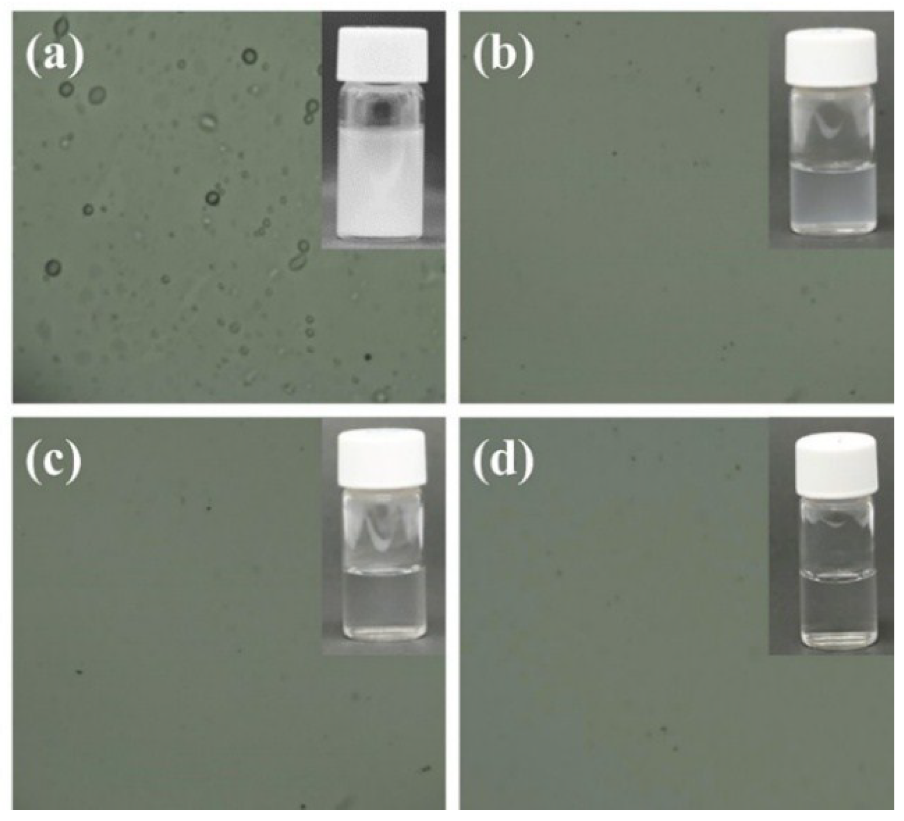
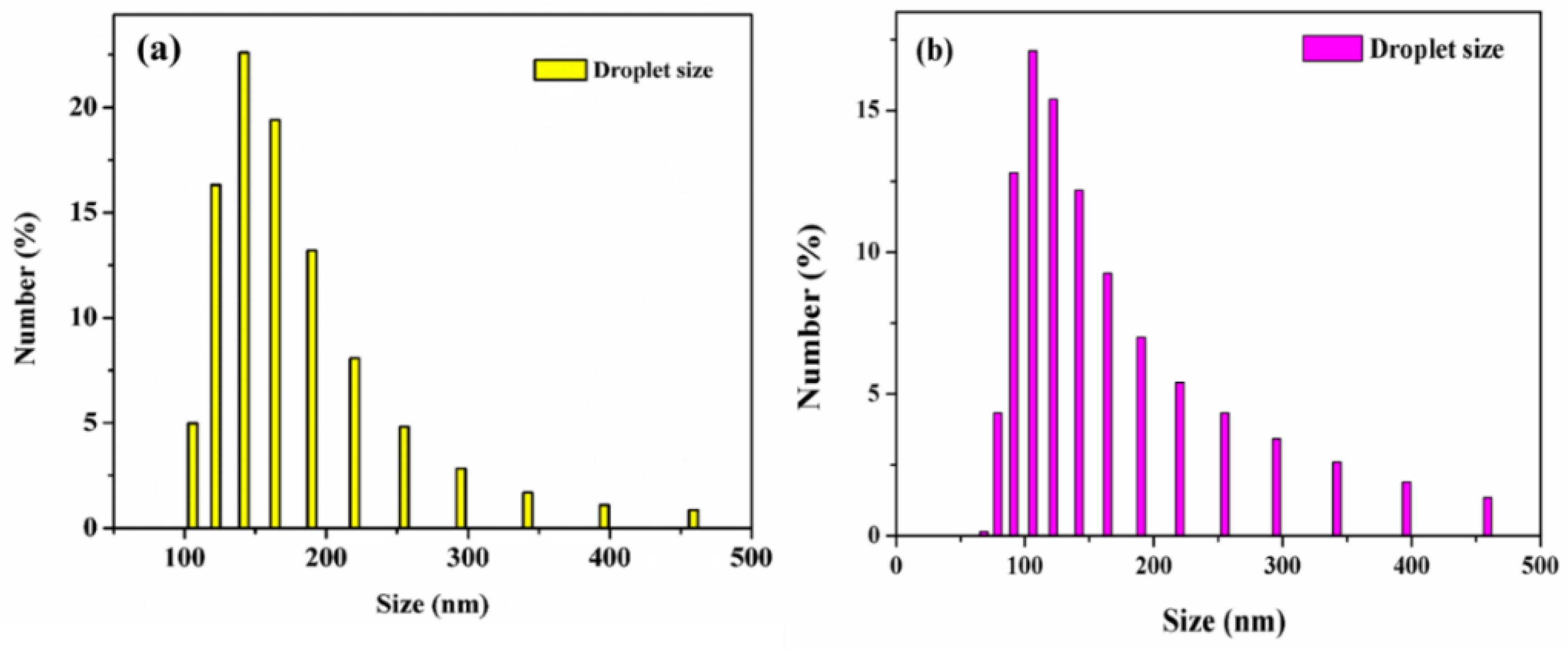
2.6. Preparation and Separation of the Oil-in-Water Emulsions
2.7. Characterizations
3. Results and Discussion
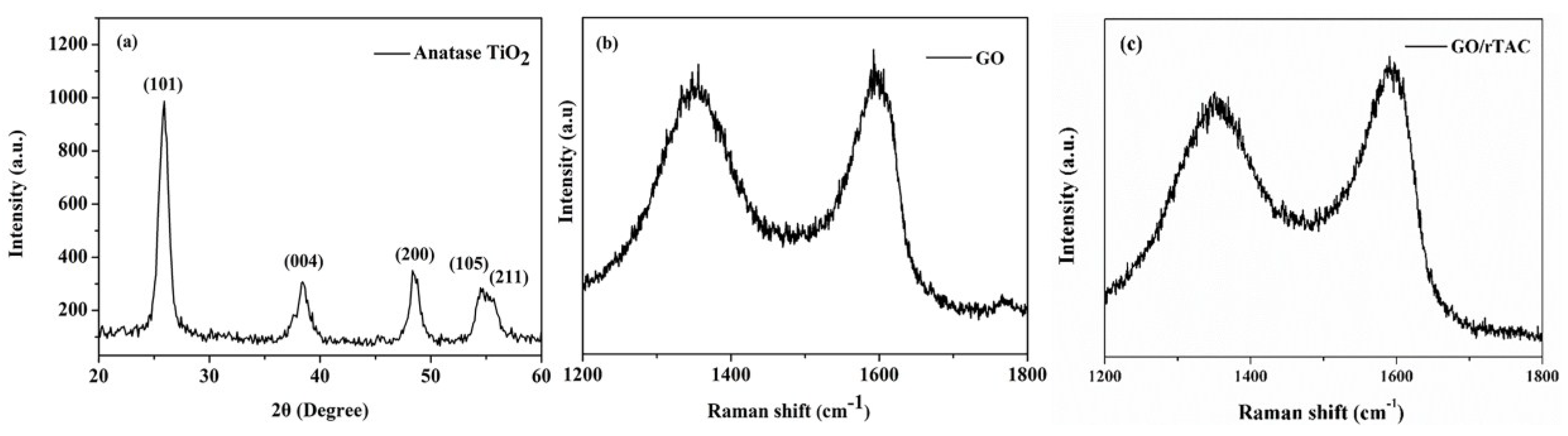
3.1. XRD
3.2. Raman Analysis
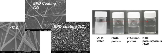
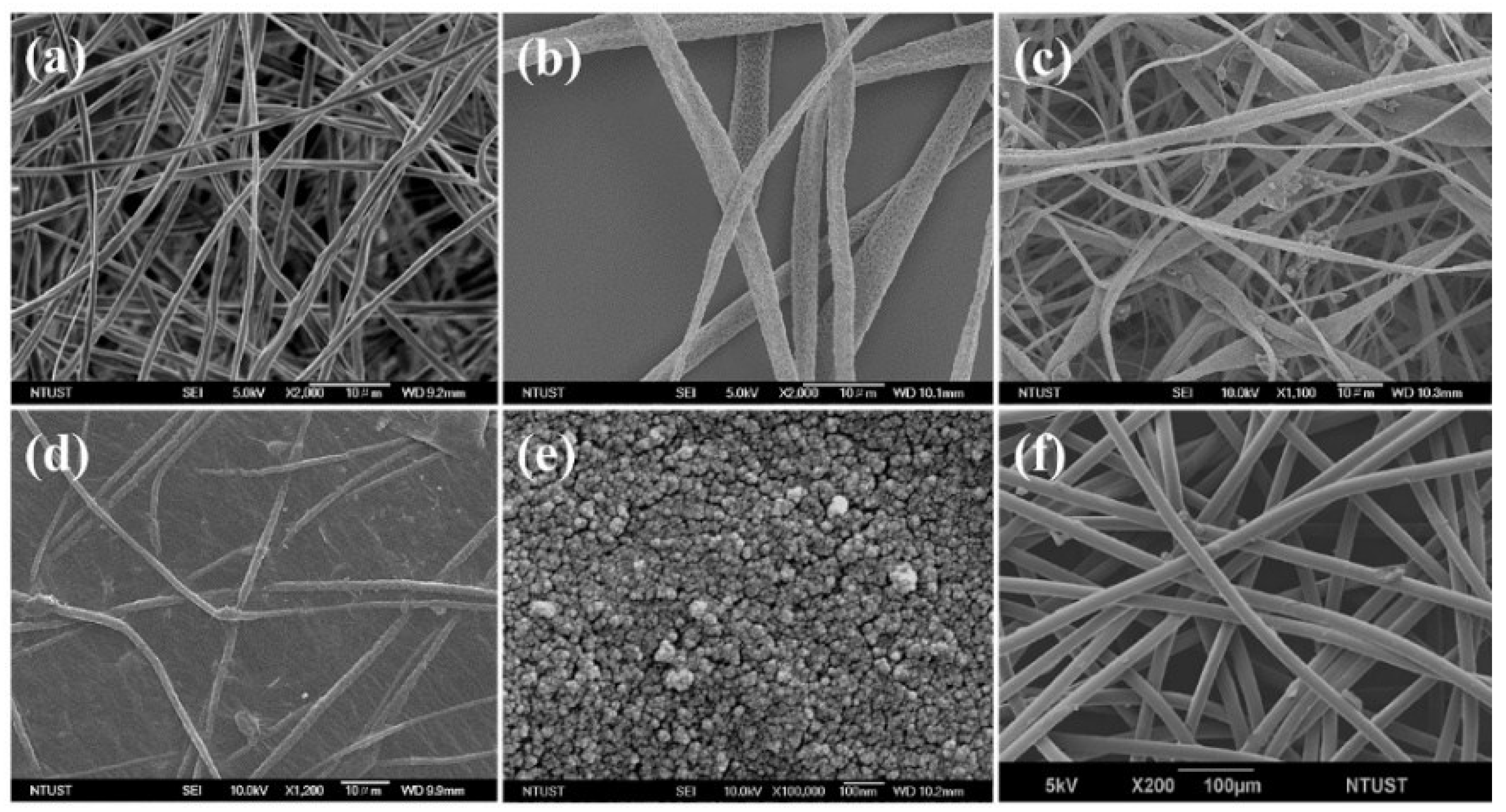
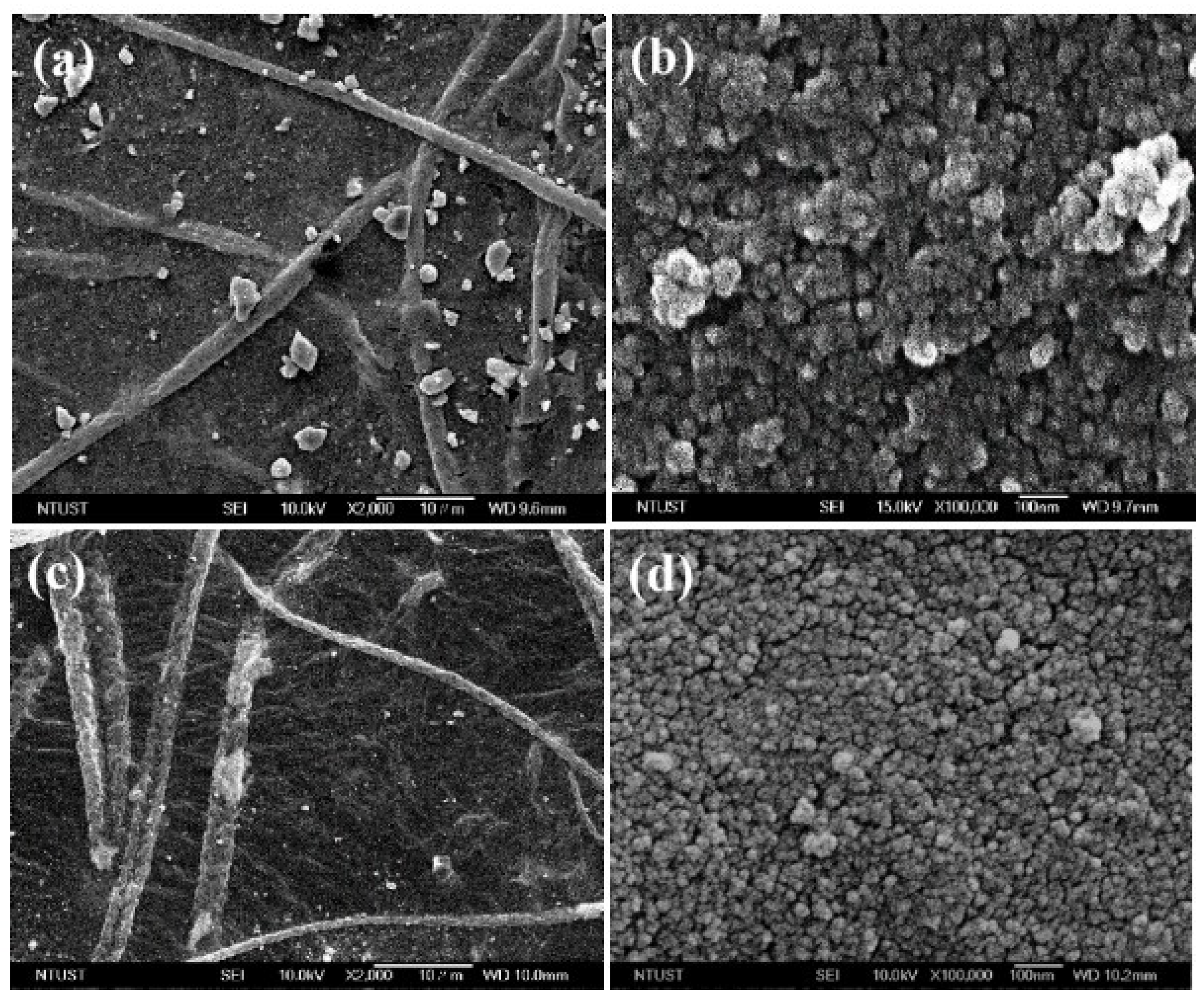
3.3. Surface Morphology
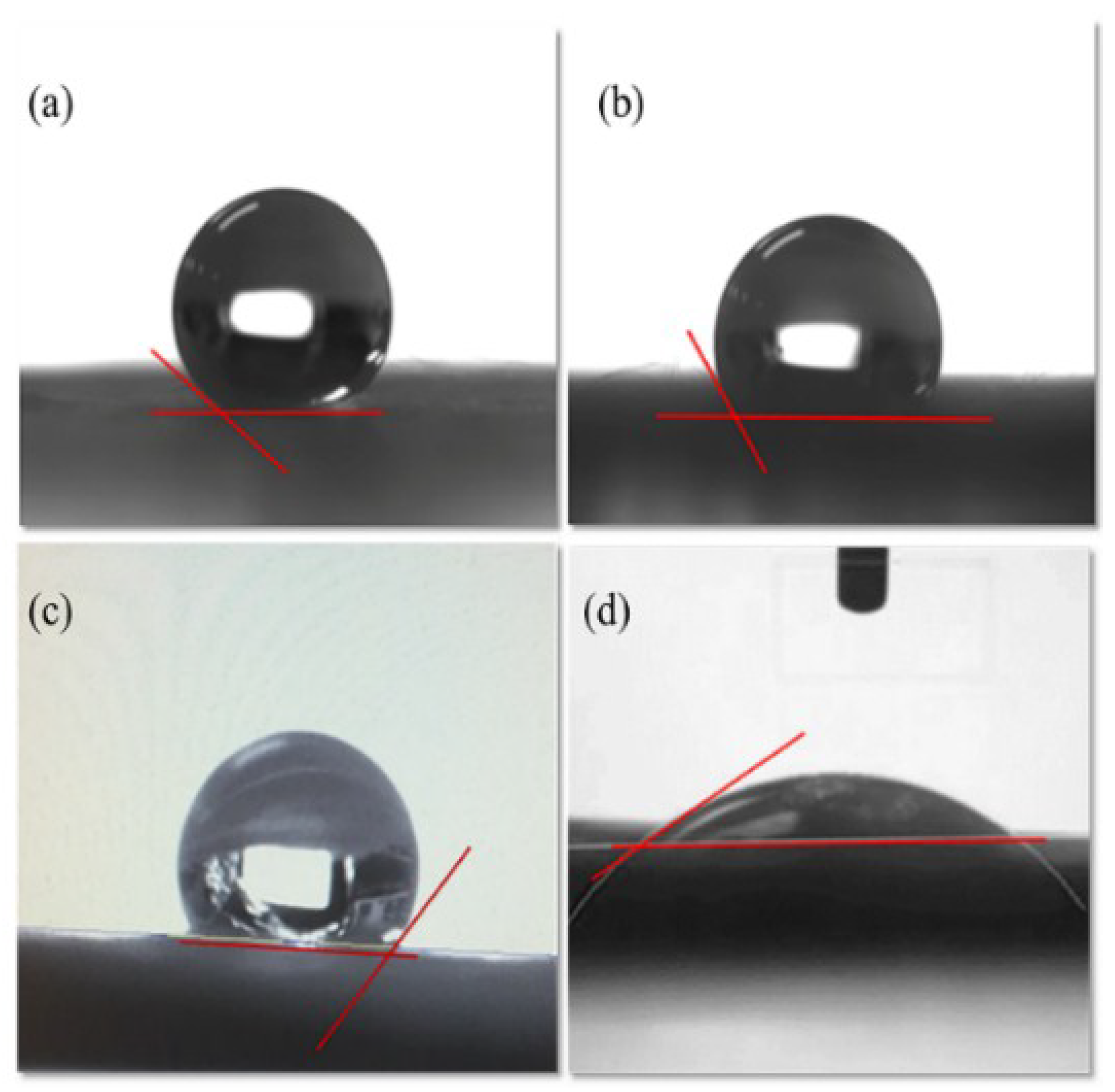
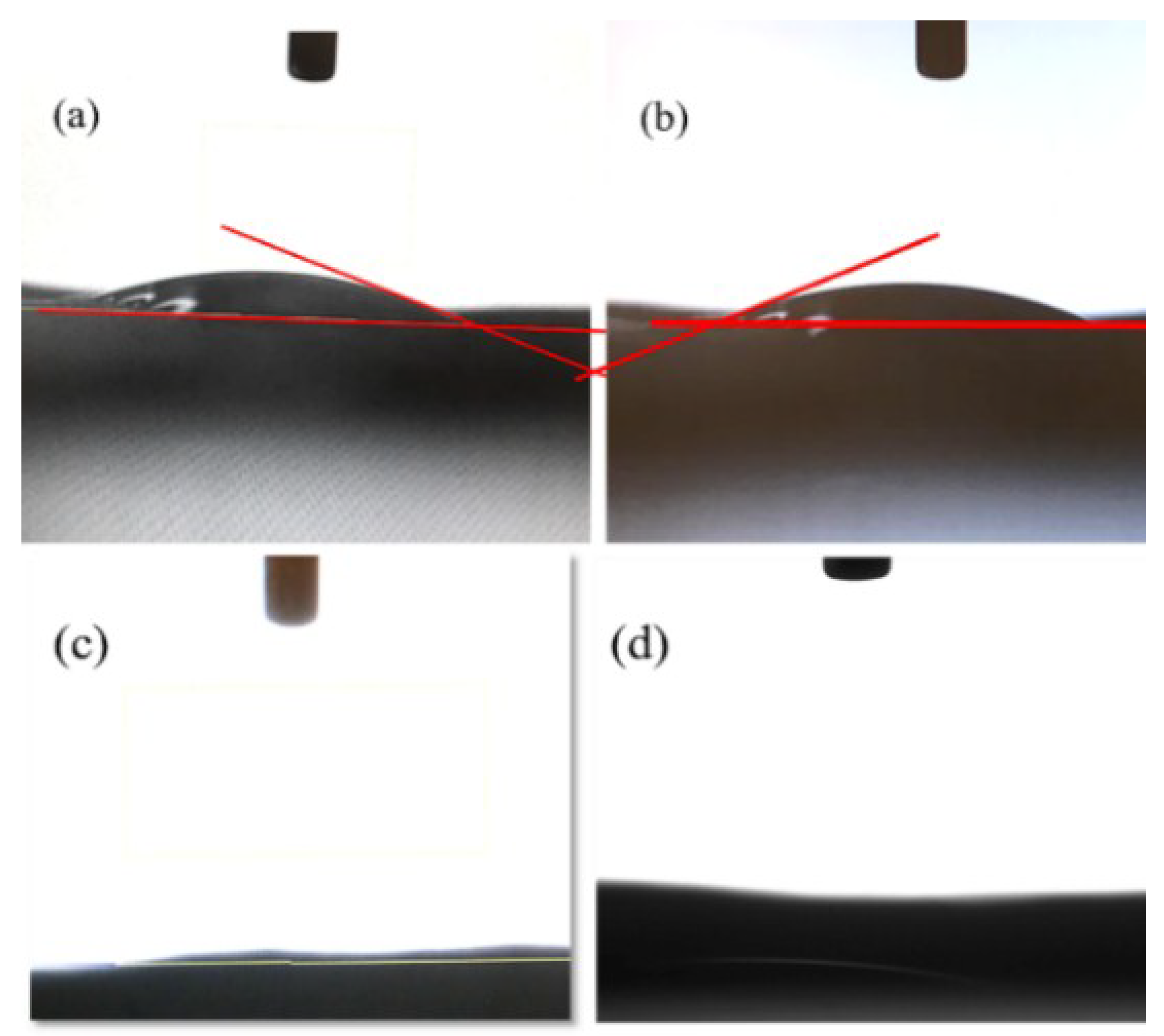
3.4. Contact Angle Analysis
4. Conclusions
Author Contributions
Funding
Conflicts of Interest
References
- Du, Y.; Li, Y.; Wu, T. A superhydrophilic and underwater superoleophobic chitosan-TiO2 composite membrane for fast oil-in-water emulsion separation. RSC Adv. 2017, 7, 41838–41846. [Google Scholar] [CrossRef]
- Gondal, M.A.; Sadullah, M.S.; Dastageer, M.A.; McKinley, G.H.; Panchanathan, D.; Varanasi, K.K. Study of factors governing oil-water separation process using TiO2 films prepared by spray deposition of nanoparticle dispersions. ACS Appl. Mater. Interfaces 2014, 6, 13422–13429. [Google Scholar] [CrossRef] [PubMed]
- Yuan, T.; Meng, J.; Hao, T.; Wang, Z.; Zhang, Y. A scalable method toward superhydrophilic and underwater superoleophobic PVDF membranes for effective oil/water emulsion separation. ACS Appl. Mater. Interfaces 2015, 7, 14896–14904. [Google Scholar] [CrossRef] [PubMed]
- Gao, S.J.; Shi, Z.; Zhang, W.B.; Zhang, F.; Jin, J. Photoinduced superwetting single-walled carbon nanotube/TiO2 ultrathin network films for ultrafast separation of oil-in-water emulsions. ACS Nano 2014, 8, 6344–6352. [Google Scholar] [CrossRef] [PubMed]
- Al-Shamrani, A.; James, A.; Xiao, H. Destabilisation of oil-water emulsions and separation by dissolved air flotation. Water Res. 2002, 36, 1503–1512. [Google Scholar] [CrossRef]
- Yoon, H.; Na, S.-H.; Choi, J.-Y.; Latthe, S.S.; Swihart, M.T.; Al-Deyab, S.S.; Yoon, S.S. Gravity-driven hybrid membrane for oleophobic–superhydrophilic oil-water separation and water purification by graphene. Langmuir 2014, 30, 11761–11769. [Google Scholar] [CrossRef] [PubMed]
- Canizares, P.; Martínez, F.; Jiménez, C.; Sáez, C.; Rodrigo, M.A. Coagulation, and electrocoagulation of oil-in-water emulsions. J. Hazard. Mater. 2008, 151, 44–51. [Google Scholar] [CrossRef] [PubMed]
- Liu, J.; Li, P.; Chen, L.; Feng, Y.; He, W.; Lv, X. Modified superhydrophilic and underwater superoleophobic PVDF membrane with ultralow oil-adhesion for highly efficient oil/water emulsion separation. Mater. Lett. 2016, 185, 169–172. [Google Scholar] [CrossRef]
- Yang, X.; He, Y.; Zeng, G.; Chen, X.; Shi, H.; Qing, D.; Li, F.; Chen, Q. Bio-inspired method for preparation of multiwall carbon nanotubes decorated superhydrophilic poly (vinylidene fluoride) membrane for oil/water emulsion separation. Chem. Eng. J. 2017, 321, 245–256. [Google Scholar] [CrossRef]
- Kwon, G.; Post, E.; Tuteja, A. Membranes with selective wettability for the separation of oil-water mixtures. MRS Commun. 2015, 5, 475–494. [Google Scholar] [CrossRef]
- Li, S.; Huang, J.; Chen, Z.; Chen, G.; Lai, Y. A review on special wettability textiles: Theoretical models, fabrication technologies, and multifunctional applications. J. Mater. Chem. A 2017, 5, 31–55. [Google Scholar] [CrossRef]
- Cao, C.; Ge, M.; Huang, J.; Li, S.; Deng, S.; Zhang, S.; Chen, Z.; Zhang, K.; Al-Deyab, S.S.; Lai, Y. Robust fluorine-free superhydrophobic PDMS-ormosil@fabrics for highly effective self-cleaning and efficient oil-water separation. J. Mater. Chem. A 2016, 4, 12179–12187. [Google Scholar] [CrossRef]
- Gao, S.; Dong, X.; Huang, J.; Li, S.; Li, Y.; Chen, Z.; Lai, Y. Rational construction of highly transparent superhydrophobic coatings based on a non-particle, fluorine-free and water-rich system for versatile oil-water separation. Chem. Eng. J. 2018, 333, 621–629. [Google Scholar] [CrossRef]
- Liu, H.; Huang, J.; Chen, Z.; Chen, G.; Zhang, K.-Q.; Al-Deyab, S.S.; Lai, Y. Robust translucent superhydrophobic PDMS/PMMA film by facile one-step spray for self-cleaning and efficient emulsion separation. Chem. Eng. J. 2017, 330, 26–35. [Google Scholar] [CrossRef]
- Ge, M.; Cao, C.; Huang, J.; Zhang, X.; Tang, Y.; Zhou, X.; Zhang, K.; Chen, Z.; Lai, Y. Rational design of materials interface at nanoscale towards intelligent oil-water separation. Nanoscale Horiz. 2018, 3, 235–260. [Google Scholar] [CrossRef]
- Zhang, S.; Lu, F.; Tao, L.; Liu, N.; Gao, C.; Feng, L.; Wei, Y. Bio-inspired anti-oil-fouling chitosan-coated mesh for oil/water separation suitable for broad pH range and hyper-saline environments. ACS Appl. Mater. Interfaces 2013, 5, 11971–11976. [Google Scholar] [CrossRef] [PubMed]
- Wang, R.; Xu, Z. Pyrolysis mechanism for recycle renewable resource from polarizing film of waste liquid crystal display panels. J. Hazard. Mater. 2014, 278, 311–319. [Google Scholar] [CrossRef] [PubMed]
- Hiroaki, S.; Masahiko, M.; Shu, S. 5.4 properties and applications of cellulose triacetate film. Macromol. Symp. 2004, 208, 323–334. [Google Scholar]
- Ryo, S.; Masato, N.; Yasuyuki, S.; Nobutaka, F.; Koji, K.; Yoji, I. 31.1: Evolution of cellulose triacetate (TAC) films for LCDs: Novel technologies for high hardness, durability, and dimensional stability. SID Symp. Dig. Tech. Pap. 2015, 46, 446–449. [Google Scholar]
- Mohanty, A.K.; Misra, M.; Drzal, L.T. Sustainable bio-composites from renewable resources: Opportunities and challenges in the green materials world. J. Polym. Environ. 2002, 10, 19–26. [Google Scholar] [CrossRef]
- Fan, L.; Yan, J.; He, H.; Deng, N.; Zhao, Y.; Kang, W.; Cheng, B. Electro-blown spun PS/PAN fibrous membrane for highly efficient oil/water separation. Fibers Polym. 2017, 18, 1988–1994. [Google Scholar] [CrossRef]
- Wang, C.; Chien, H.-S.; Hsu, C.-H.; Wang, Y.-C.; Wang, C.-T.; Lu, H.-A. Electrospinning of polyacrylonitrile solutions at elevated temperatures. Macromolecules 2007, 40, 7973–7983. [Google Scholar] [CrossRef]
- Nayani, K.; Katepalli, H.; Sharma, C.S.; Sharma, A.; Patil, S.; Venkataraghavan, R. Electrospinning combined with nonsolvent-induced phase separation to fabricate highly porous and hollow submicrometer polymer fibers. Ind. Eng. Chem. Res. 2012, 51, 1761–1766. [Google Scholar] [CrossRef]
- Han, S.O.; Son, W.K.; Youk, J.H.; Lee, T.S.; Park, W.H. Ultrafine porous fibers electrospun from cellulose triacetate. Mater. Lett. 2005, 59, 2998–3001. [Google Scholar] [CrossRef]
- Song, Z.; Chiang, S.W.; Chu, X.; Du, H.; Li, J.; Gan, L.; Xu, C.; Yao, Y.; He, Y.; Li, B. Effects of solvent on structures and properties of electrospun poly (ethylene oxide) nanofibers. J. Appl. Polym. Sci. 2018, 135, 45787. [Google Scholar] [CrossRef]
- Wang, X.; Yu, J.; Sun, G.; Ding, B. Electrospun nanofibrous materials: A versatile medium for effective oil/water separation. Mater. Today 2016, 19, 403–414. [Google Scholar] [CrossRef]
- Cao, Z.; Li, S.; Zhang, J.; Zhang, H. An electro-microbial membrane system with anti-fouling function for phenol wastewater treatment. J. Chem. Technol. Biotechnol. 2017, 92, 693–699. [Google Scholar] [CrossRef]
- Nevstrueva, D.; Pihlajamäki, A.; Mänttäri, M. Effect of a TiO2 additive on the morphology and permeability of cellulose ultrafiltration membranes prepared via immersion precipitation with ionic liquid as a solvent. Cellulose 2015, 22, 3865–3876. [Google Scholar] [CrossRef]
- Xu, C.; Cui, A.; Xu, Y.; Fu, X. Graphene oxide–TiO2 composite filtration membranes and their potential application for water purification. Carbon 2013, 62, 465–471. [Google Scholar] [CrossRef]
- Takeuchi, M.; Sakamoto, K.; Martra, G.; Coluccia, S.; Anpo, M. Mechanism of photoinduced superhydrophilicity on the TiO2 photocatalyst surface. J. Phys. Chem. B 2005, 109, 15422–15428. [Google Scholar] [CrossRef] [PubMed]
- Horandghadim, N.; Ghorbani, M.; Dolati, A. In Self-cleaning TiO2 nanofilms on fto glass: Influence of electrophoretic deposition and uv irradiation conditions. J. Nano Res. 2015, 30, 39–49. [Google Scholar] [CrossRef]
- Chen, Q.; Yu, Z.; Pan, Y.; Zeng, G.; Shi, H.; Yang, X.; Li, F.; Yang, S.; He, Y. Enhancing the photocatalytic and antibacterial property of polyvinylidene fluoride membrane by blending Ag–TiO2 nanocomposites. J. Mater. Sci. Mater. Electron. 2017, 28, 3865–3874. [Google Scholar] [CrossRef]
- Liu, K.; Cao, M.; Fujishima, A.; Jiang, L. Bio-inspired titanium dioxide materials with special wettability and their applications. Chem. Rev. 2014, 114, 10044–10094. [Google Scholar] [CrossRef] [PubMed]
- Chen, Q.; Yu, Z.; Li, F.; Yang, Y.; Pan, Y.; Peng, Y.; Yang, X.; Zeng, G. A novel photocatalytic membrane decorated with rGO-Ag- TiO2 for dye degradation and oil-water emulsion separation. J. Chem. Technol. Biotechnol. 2018, 93, 761–775. [Google Scholar] [CrossRef]
- Yuekun, L.; Jianying, H.; Zequn, C.; Mingzheng, G.; Ke-Qin, Z.; Zhong, C.; Lifeng, C. Recent advances in TiO2-based nanostructured surfaces with controllable wettability and adhesion. Small 2016, 12, 2203–2224. [Google Scholar]
- Dreyer, D.R.; Park, S.; Bielawski, C.W.; Ruoff, R.S. The chemistry of graphene oxide. Chem. Soc. Rev. 2010, 39, 228–240. [Google Scholar] [CrossRef] [PubMed]
- Li, F.; Yu, Z.; Shi, H.; Yang, Q.; Chen, Q.; Pan, Y.; Zeng, G.; Yan, L. A mussel-inspired method to fabricate reduced graphene oxide/g-C3N4 composites membranes for catalytic decomposition and oil-in-water emulsion separation. Chem. Eng. J. 2017, 322, 33–45. [Google Scholar] [CrossRef]
- Jiang, Y.; Biswas, P.; Fortner, J.D. A review of recent developments in graphene-enabled membranes for water treatment. Environ. Sci. Water Res. Technol. 2016, 2, 915–922. [Google Scholar] [CrossRef]
- Junaidi, N.F.D.; Khalil, N.A.; Jahari, A.F.; Shaari, N.Z.K.; Shahruddin, M.Z.; Alias, N.H.; Othman, N.H. Effect of graphene oxide (GO) on the surface morphology & hydrophilicity of polyethersulfone (pes). IOP Conf. Ser. Mater. Sci. Eng. 2018, 358, 012047. [Google Scholar]
- Gao, P.; Liu, Z.; Tai, M.; Sun, D.D.; Ng, W. Multifunctional graphene oxide–TiO2 microsphere hierarchical membrane for clean water production. Appl. Catal. B Environ. 2013, 138–139, 17–25. [Google Scholar] [CrossRef]
- Safarpour, M.; Vatanpour, V.; Khataee, A. Preparation and characterization of graphene oxide/TiO2 blended pes nanofiltration membrane with improved antifouling and separation performance. Desalination 2016, 393, 65–78. [Google Scholar] [CrossRef]
- Yang, Y.; Qiu, M.; Liu, L. TiO2 nanorod array@ carbon cloth photocatalyst for CO2 reduction. Ceram. Int. 2016, 42, 15081–15086. [Google Scholar] [CrossRef]
- Wu, C.M.; Huang, C.C.; Yang, X.J. Fabrication and photocatalytic activity of porous recycled cellulose triacetate nanofibrous membranes embedded with TiO2. In Proceedings of the CAMX 2016—Composites and Advanced Materials Expo, Anaheim, CA, USA, 26–29 September 2016. [Google Scholar]
- Diba, M.; Fam, D.W.H.; Boccaccini, A.R.; Shaffer, M.S.P. Electrophoretic deposition of graphene-related materials: A review of the fundamentals. Prog. Mater. Sci. 2016, 82, 83–117. [Google Scholar] [CrossRef] [Green Version]
- Lam, S.W.; Chiang, K.; Lim, T.M.; Amal, R.; Low, G.K.-C. Electrophoresis—A new approach for the determination of organic matters adsorption on irradiated TiO2. J. Photochem. Photobiol. A Chem. 2007, 187, 127–132. [Google Scholar] [CrossRef]
- Cabanas-Polo, S.; Boccaccini, A.R. Electrophoretic deposition of nanoscale TiO2: Technology and applications. J. Eur. Ceram. Soc. 2016, 36, 265–283. [Google Scholar] [CrossRef]
- Hosseinpour, A.; Abdizadeh, H.; Golobostanfard, M.R. Comparing the electrophoretic deposition process of graphene oxides synthesized through different methods. Thin Solid Films 2017, 631, 118–123. [Google Scholar] [CrossRef]
- Nasouri, K.; Shoushtari, A.M.; Mojtahedi, M.R.M. Effects of polymer/solvent systems on electrospun polyvinylpyrrolidone nanofiber morphology and diameter. Polym. Sci. Ser. A 2015, 57, 747–755. [Google Scholar] [CrossRef]
- Li, Y.; Lim, C.T.; Kotaki, M. Study on structural and mechanical properties of porous pla nanofibers electrospun by channel-based electrospinning system. Polymer 2015, 56, 572–580. [Google Scholar] [CrossRef]
- Wu, Z.; Zhang, C.; Peng, K.; Wang, Q.; Wang, Z. Hydrophilic/underwater superoleophobic graphene oxide membrane intercalated by TiO2 nanotubes for oil/water separation. Front. Environ. Sci. Eng. 2018, 12, 15. [Google Scholar] [CrossRef]
- Liu, Y.-Q.; Zhang, Y.-L.; Fu, X.-Y.; Sun, H.-B. Bioinspired underwater superoleophobic membrane based on a graphene oxide coated wire mesh for efficient oil/water separation. ACS Appl. Mater. Interfaces 2015, 7, 20930–20936. [Google Scholar] [CrossRef] [PubMed]
- Sakai, N.; Fujishima, A.; Watanabe, T.; Hashimoto, K. Quantitative evaluation of the photoinduced hydrophilic conversion properties of TiO2 thin film surfaces by the reciprocal of contact angle. J. Phys. Chem. B 2003, 107, 1028–1035. [Google Scholar] [CrossRef]
- Shi, H.; He, Y.; Pan, Y.; Di, H.; Zeng, G.; Zhang, L.; Zhang, C. A modified mussel-inspired method to fabricate TiO2 decorated superhydrophilic PVDF membrane for oil/water separation. J. Membr. Sci. 2016, 506, 60–70. [Google Scholar] [CrossRef]
- Wang, R.; Hashimoto, K.; Fujishima, A.; Chikuni, M.; Kojima, E.; Kitamura, A.; Shimohigoshi, M.; Watanabe, T. Light-induced amphiphilic surfaces. Nature 1997, 388, 431–432. [Google Scholar] [CrossRef]
- Nouh, S.A.; Wahab, L.A.; Eissa, H.M. The effect of uv radiation on the thermal degradation of cellulose triacetate. Radiat. Meas. 1999, 30, 753–757. [Google Scholar] [CrossRef]


| Samples | Raw n-Hexadecane Oil (ppm) | SDS Stabilized n-Hexadecane Oil Emulsion (ppm) |
|---|---|---|
| Oil in feed | 1500 | 1500 |
| TiO2/GO/rTAC-p | 29.00 | 235.9 |
| TiO2/GO/rTAC-n | 22.65 | 235.5 |
| TiO2/GO/rTAC-np | 16.92 | 177.2 |
© 2018 by the authors. Licensee MDPI, Basel, Switzerland. This article is an open access article distributed under the terms and conditions of the Creative Commons Attribution (CC BY) license (http://creativecommons.org/licenses/by/4.0/).
Share and Cite
Naseem, S.; Wu, C.-M.; Xu, T.-Z.; Lai, C.-C.; Rwei, S.-P. Oil-Water Separation of Electrospun Cellulose Triacetate Nanofiber Membranes Modified by Electrophoretically Deposited TiO2/Graphene Oxide. Polymers 2018, 10, 746. https://doi.org/10.3390/polym10070746
Naseem S, Wu C-M, Xu T-Z, Lai C-C, Rwei S-P. Oil-Water Separation of Electrospun Cellulose Triacetate Nanofiber Membranes Modified by Electrophoretically Deposited TiO2/Graphene Oxide. Polymers. 2018; 10(7):746. https://doi.org/10.3390/polym10070746
Chicago/Turabian StyleNaseem, Saba, Chang-Mou Wu, Ting-Zhen Xu, Chiu-Chun Lai, and Syang-Peng Rwei. 2018. "Oil-Water Separation of Electrospun Cellulose Triacetate Nanofiber Membranes Modified by Electrophoretically Deposited TiO2/Graphene Oxide" Polymers 10, no. 7: 746. https://doi.org/10.3390/polym10070746