Synthesis and Performances of Phase Change Microcapsules with a Polymer/Diatomite Hybrid Shell for Thermal Energy Storage

Abstract
:
1. Introduction
2. Experimental
2.1. Materials
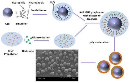
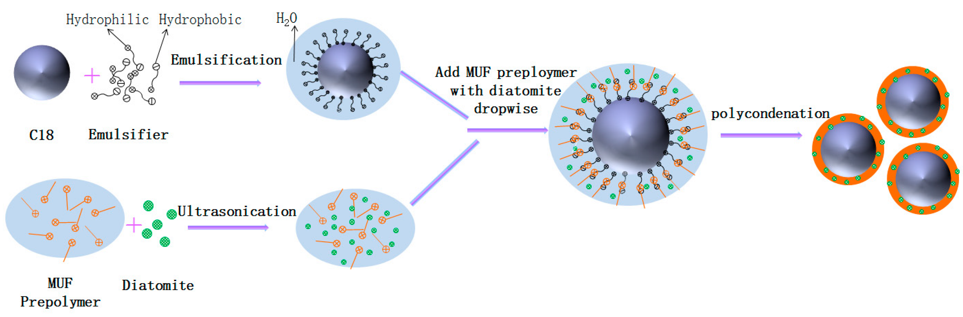
2.2. Synthesis of microPCMs with MUF/Diatomite Hybrid Shell
2.3. Characterization
2.3.1. Fourier Transform Infrared
2.3.2. Scanning Electron Microscopy Observation and Particle Size Analysis
2.3.3. Differential Scanning Calorimeter
2.3.4. Thermalgravimetric Analysis
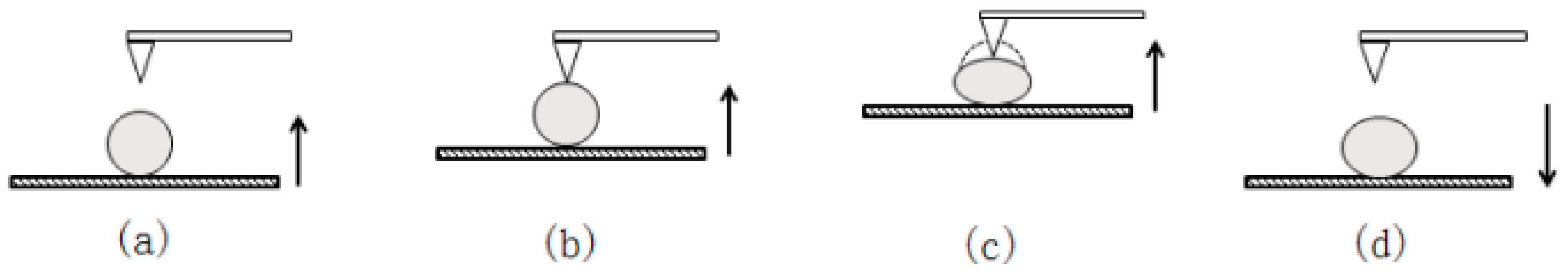
2.3.5. Mechanical Properties
3. Results and Discussion
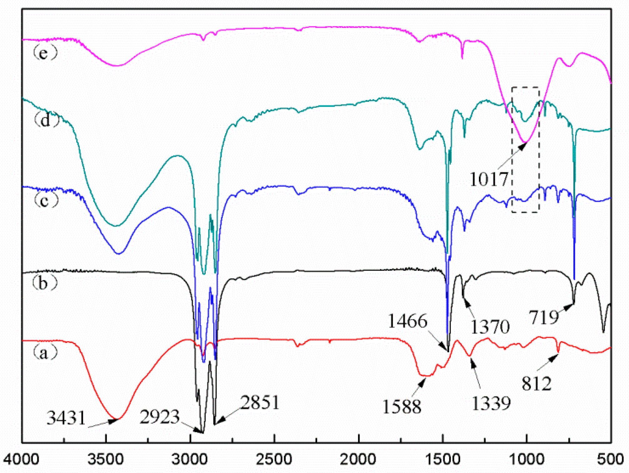
3.1. FTIR Spectra
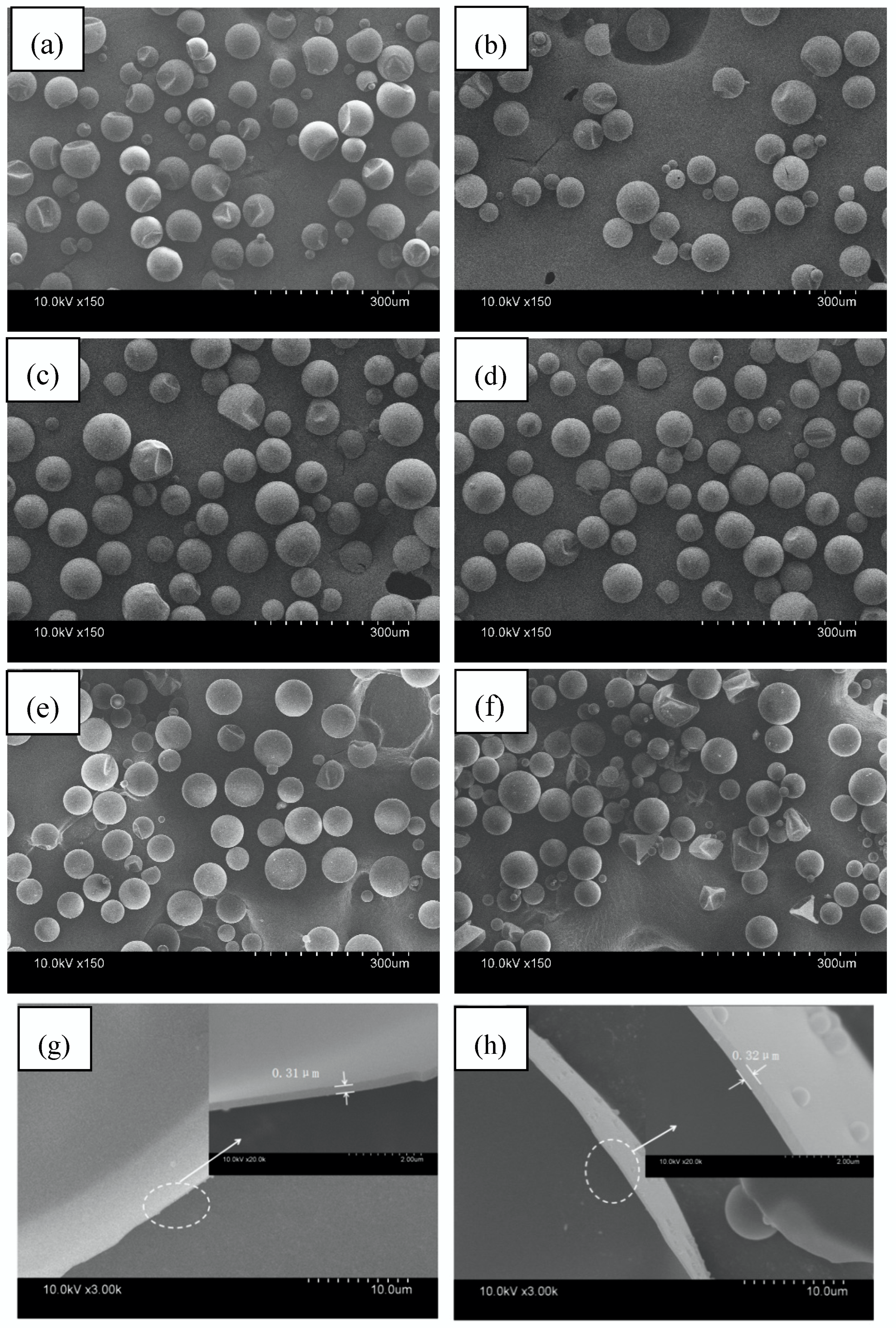
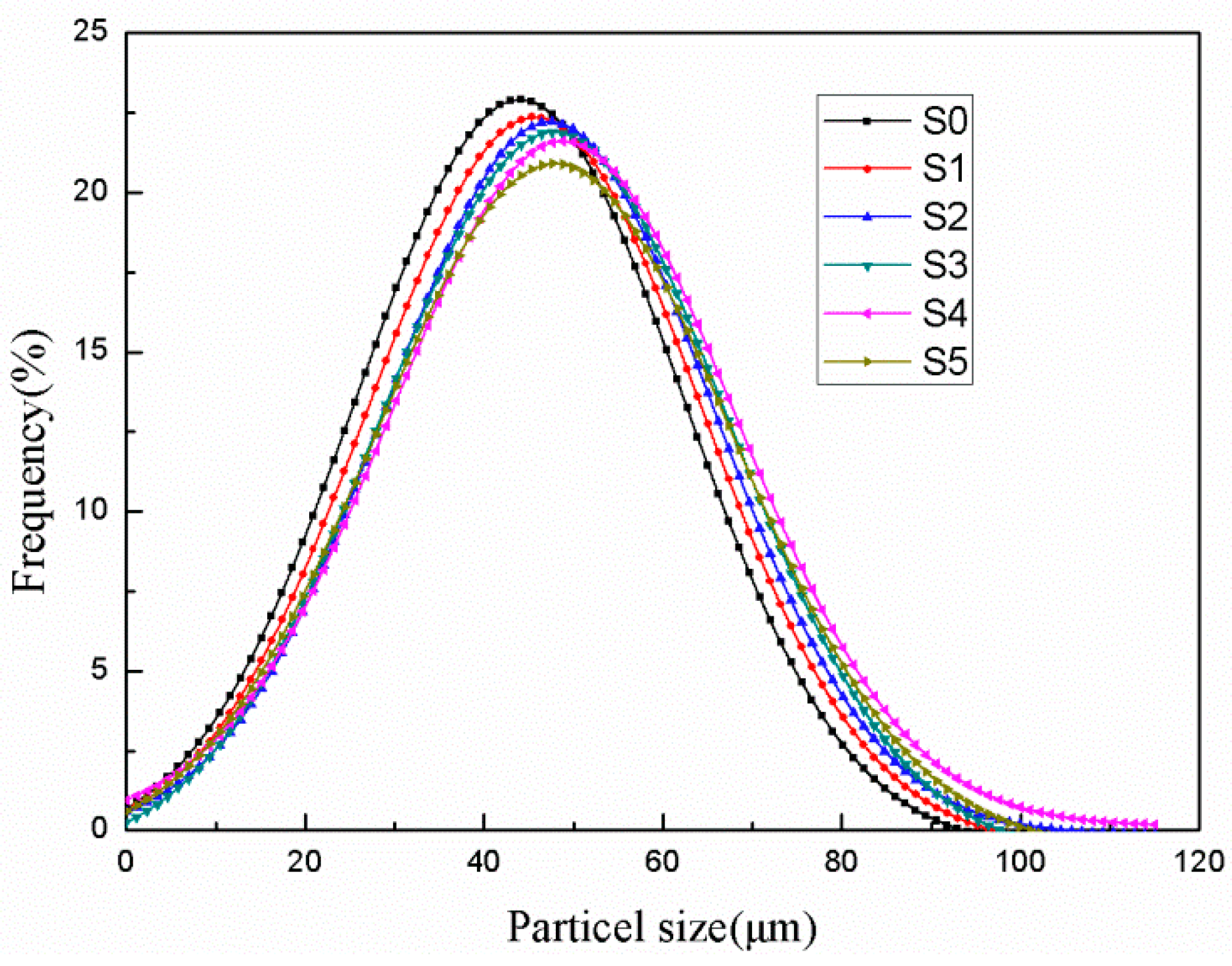
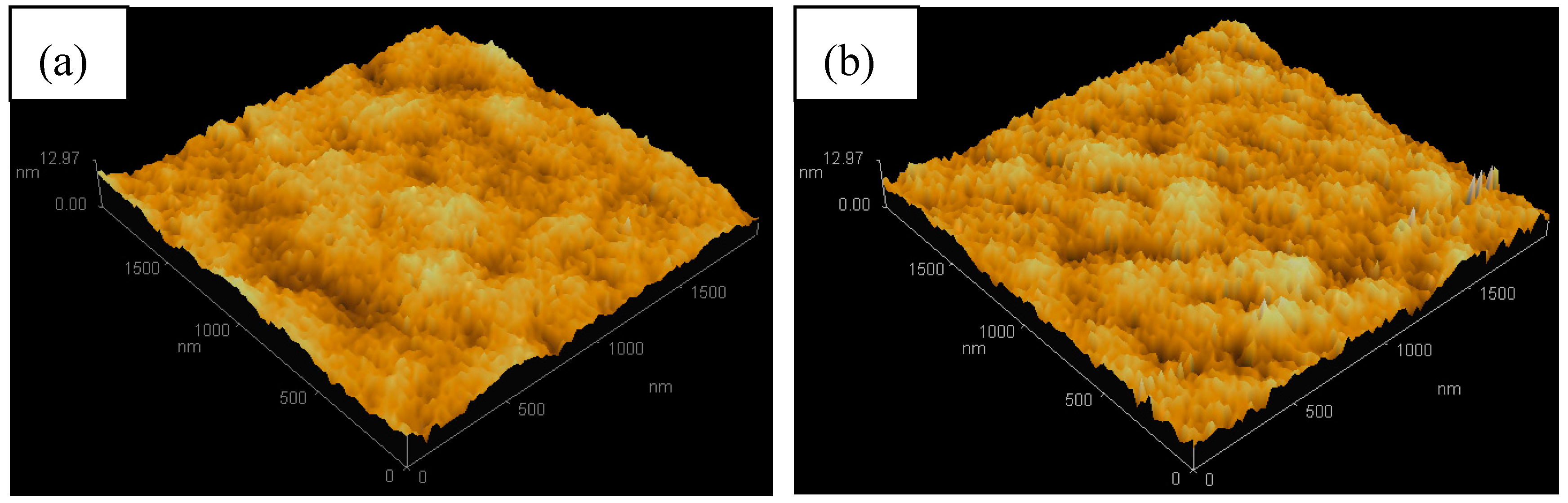
3.2. Morphology, Wall Thicknesses, and Particle Size Distribution
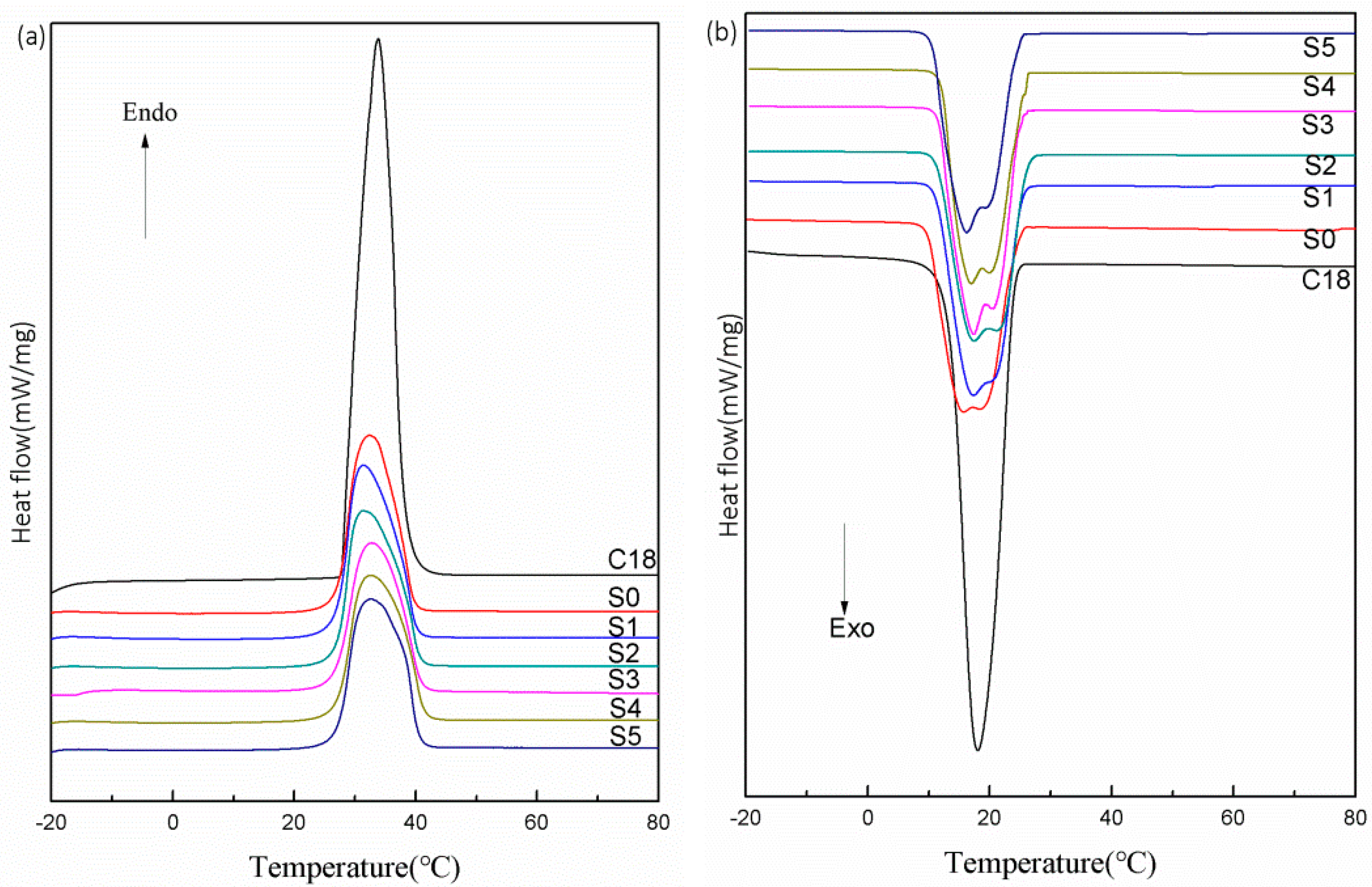
3.3. Phase-Change Properties and Thermal Storage Capability
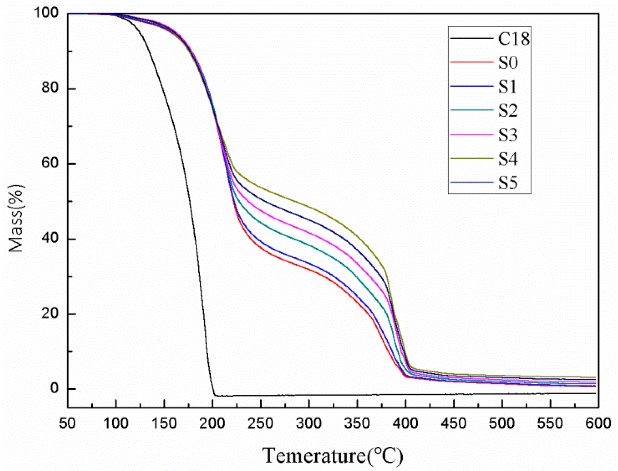
3.4. Thermal Stability
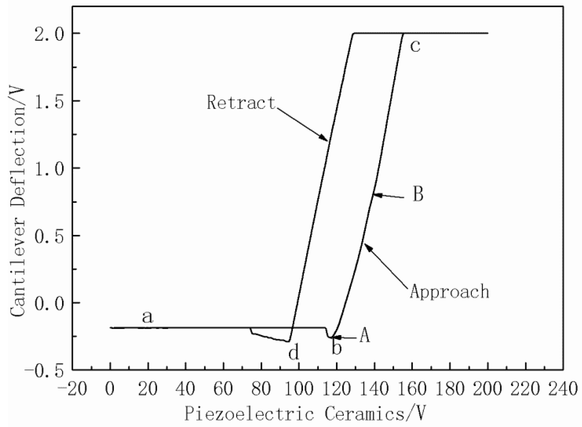
3.5. Mechanical Properties
4. Conclusions
Author Contributions
Acknowledgments
Conflicts of Interest
References
- Jiang, Z.; Yang, W.; He, F.; Xie, C.; Fan, J.; Wu, J.; Zhang, K. Modified phase change microcapsules with calcium carbonate and graphene oxide shell for enhanced energy storage and leakage prevention. ACS Sustain. Chem. Eng. 2018, 6, 5182–5191. [Google Scholar] [CrossRef]
- Wang, T.; Jiang, Y.; Huang, J.; Wang, S. High thermal conductive paraffin/calcium carbonate phase change microcapsules based composites with different carbon network. Appl. Energy 2018, 218, 184–191. [Google Scholar] [CrossRef]
- Hussien, H.; Abed, A.; Abdulmunem, A. An experimental investigation of using aluminum foam matrix integrated with paraffin wax as a thermal storage material in a solar heater. In Proceedings of the 2nd Sustainable Renewable Energy Conference, Baghdad, Iraq, 26–27 November 2016. [Google Scholar]
- Dorigato, A.; Ciampolillo, M.V.; Cataldi, A.; Bersani, M.; Pegoretti, A. Polyethylene wax/EPDM blends as shape-stabilized phase change materials for thermal energy storage. Rubber Chem. Technol. 2017, 90, 575–584. [Google Scholar] [CrossRef]
- Fredi, G.; Dorigato, A.; Pegoretti, A. Multifunctional glass fiber/polyamide composites with thermal energy storage/release capability. Express Polym. Lett. 2018, 12, 349–364. [Google Scholar] [CrossRef]
- Fredi, G.; Dorigato, A.; Fambri, L.; Pegoretti, A. Wax confinement with carbon nanotubes for phase changing epoxy blends. Polymers 2017, 9, 405. [Google Scholar] [CrossRef]
- Yang, J.; Zhang, E.; Li, X.; Zhang, Y.; Qu, J.; Yu, Z. Cellulose/graphene aerogel supported phase change composites with high thermal conductivity and good shape stability for thermal energy storage. Carbon 2016, 98, 50–57. [Google Scholar] [CrossRef]
- Fredi, G.; Dorigato, A.; Fambri, L.; Pegoretti, A. Multifunctional epoxy/carbon fiber laminates for thermal energy storage and release. Compos. Sci. Technol. 2018, 158, 101–111. [Google Scholar] [CrossRef]
- Dorigato, A.; Canclini, P.; Unterberger, S.; Pegoretti, A. Phase changing nanocomposites for low temperature thermal energy storage and release. Express Polym. Lett. 2017, 11, 738–752. [Google Scholar] [CrossRef]
- Liu, Z.; Chen, Z.; Yu, F. Microencapsulated phase change material modified by graphene oxide with different degrees of oxidation for solar energy storage. Sol. Energy Mater. Sol. Cells 2018, 174, 453–459. [Google Scholar] [CrossRef]
- Yang, Y.; Kuang, J.; Wang, H.; Song, G.; Liu, Y.; Tang, G. Enhancement in thermal property of phase change microcapsules with modified silicon nitride for solar energy. Sol. Energy Mater. Sol. Cells 2016, 151, 89–95. [Google Scholar] [CrossRef]
- Zheng, L.; Zhang, W.; Liang, F. A review about phase change material cold storage system applied to solar-powered air-conditioning system. Adv. Mech. Eng. 2017, 9, 1687814017705844. [Google Scholar] [CrossRef]
- Lei, J.; Yang, J.; Yang, E. Energy performance of building envelopes integrated with phase change materials for cooling load reduction in tropical singapore. Appl. Energy 2016, 162, 207–217. [Google Scholar] [CrossRef]
- Shin, Y.; Yoo, D.I.; Son, K. Development of thermoregulating textile materials with microencapsulated phase change materials (PCM). IV. performance properties and hand of fabrics treated with PCM microcapsules. Appl. Polym. Sci. 2005, 97, 910–915. [Google Scholar] [CrossRef]
- Li, W.; Zhang, X.; Wang, X.; Niu, J. Preparation and characterization of microencapsulated phase change material with low remnant formaldehyde content. Mater. Chem. Phys. 2007, 106, 437–442. [Google Scholar] [CrossRef]
- Cao, F.; Yang, B. Supercooling suppression of microencapsulated phase change materials by optimizing shell composition and structure. Appl. Energy 2014, 113, 1512–1518. [Google Scholar] [CrossRef]
- Ma, Y.; Chu, X.; Li, W.; Tang, G. Preparation and characterization of poly(methyl methacrylate-co-divinylbenzene) microcapsules containing phase change temperature adjustable binary core materials. Sol. Energy 2012, 86, 2056–2066. [Google Scholar] [CrossRef]
- Lu, S.; Shen, T.; Xing, J.; Song, Q.; Shao, J.; Zhang, J.; Xin, C. Preparation and characterization of cross-linked polyurethane shell microencapsulated phase change materials by interfacial polymerization. Mater. Lett. 2017, 211, 36–39. [Google Scholar] [CrossRef]
- Wang, T.; Wang, S.; Luo, R.; Zhu, C.; Akiyama, T.; Zhang, Z. Microencapsulation of phase change materials with binary cores and calcium carbonate shell for thermal energy storage. Appl. Energy 2016, 171, 113–119. [Google Scholar] [CrossRef]
- Jiang, B.; Wang, X.; Wu, D. Fabrication of microencapsulated phase change materials with TiO2/Fe3O4 hybrid shell as thermoregulatory enzyme carriers: A novel design of applied energy microsystem for bioapplications. Appl. Energy 2017, 201, 20–33. [Google Scholar] [CrossRef]
- Zhang, H.; Sun, S.; Wang, X.; Wu, D. Fabrication of microencapsulated phase change materials based on N-octadecane core and silica shell through interfacial polycondensation. Colloids Surf. A 2011, 389, 104–117. [Google Scholar] [CrossRef]
- Song, Q.; Li, Y.; Xing, J.; Hu, J.; Marcus, Y. Thermal stability of composite phase change material microcapsules incorporated with silver nano-particles. Polymer 2007, 48, 3317–3323. [Google Scholar] [CrossRef]
- Yin, D.; Liu, H.; Ma, L.; Zhang, Q. Fabrication and performance of microencapsulated phase change materials with hybrid shell by in situ polymerization in pickering emulsion. Polym. Adv. Technol. 2015, 26, 613–619. [Google Scholar] [CrossRef]
- Jiang, X.; Luo, R.; Peng, F.; Fang, Y.; Akiyama, T.; Wang, S. Synthesis, characterization and thermal properties of paraffin microcapsules modified with nano-Al2O3. Appl. Energy 2015, 137, 731–737. [Google Scholar] [CrossRef]
- Wu, B.; Zheng, G.; Chen, X. Effect of graphene on the thermophysical properties of melamine-urea-formaldehyde/N-hexadecane microcapsules. RSC Adv. 2015, 5, 74024–74031. [Google Scholar] [CrossRef]
- Cui, W.; Xia, Y.; Zhang, H.; Xu, F.; Zou, Y.; Xiang, C.; Chu, H.; Qiu, S.; Sun, L. Microencapsulation of phase change materials with carbon nanotubes reinforced shell for enhancement of thermal conductivity. Mater. Sci. Eng. Conf. Ser. 2017, 182, 012015. [Google Scholar] [CrossRef]
- Sun, Y.; Wang, R.; Liu, X.; Li, M.; Yang, H.; Li, B. Improvements in the thermal conductivity and mechanical properties of phase-change microcapsules with oxygen-plasma-modified multiwalled carbon nanotubes. J. Appl. Polym. Sci. 2017, 134, 45269. [Google Scholar] [CrossRef]
- Xu, B.; Li, Z. Paraffin/diatomite/multi-wall carbon nanotubes composite phase change material tailor-made for thermal energy storage cement-based composites. Energy 2014, 72, 371–380. [Google Scholar] [CrossRef]
- Li, X.; Sanjayan, J.; Wilson, J. Fabrication and stability of form-stable diatomite/paraffin phase change material composites. Energy Build. 2014, 76, 284–294. [Google Scholar] [CrossRef]
- Giro-Paloma, J.; Oncins, G.; Barreneche, C.; Martínez, M.; Fernández, I.; Cabeza, L. Physico-chemical and mechanical properties of microencapsulated phase change material. Appl. Energy 2013, 109, 441–448. [Google Scholar] [CrossRef]
- Zhao, J.; Yang, Y.; Li, Y.; Zhao, L.; Wang, H.; Song, G.; Tang, G. Microencapsulated phase change materials with TiO2-doped pmma shell for thermal energy storage and UV-shielding. Sol. Energy Mater. Sol. Cells 2017, 168, 62–68. [Google Scholar] [CrossRef]
- Chen, L.; Zhang, L.; Tang, R.; Lu, Y. Synthesis and thermal properties of phase-change microcapsules incorporated with nano alumina particles in the shell. J. Appl. Polym. Sci. 2012, 124, 689–698. [Google Scholar] [CrossRef]
- Wang, H.; Zhao, L.; Song, G.; Tang, G.; Shi, X. Organic-inorganic hybrid shell microencapsulated phase change materials prepared from SiO2 /TiC-stabilized pickering emulsion polymerization. Sol. Energy Mater. Sol. Cells 2018, 175, 102–110. [Google Scholar] [CrossRef]
- Zhang, X.; Wang, X.; Wu, D. Design and synthesis of multifunctional microencapsulated phase change materials with silver/silica double-layered shell for thermal energy storage, electrical conduction and antimicrobial effectiveness. Energy 2016, 111, 498–512. [Google Scholar] [CrossRef]
- Zhao, L.; Luo, J.; Wang, H.; Song, G.; Tang, G. Self-assembly fabrication of microencapsulated N-octadecane with natural silk fibroin shell for thermal-regulating textiles. Appl. Therm. Eng. 2016, 99, 495–501. [Google Scholar] [CrossRef]
- Huang, Y.; Zhang, H.; Wan, X.; Chen, D.; Chen, X.; Ye, X.; Ouyang, X.; Qin, S.; Wen, H.; Tang, J. Carbon nanotube-enhanced double-walled phase-change microcapsules for thermal energy storage. J. Mater. Chem. A 2017, 5, 7482–7493. [Google Scholar] [CrossRef]
- Li, M.; Liu, T.; Hu, L.; Wang, Y.; Gao, L. Fabrication and properties of microencapsulated paraffin@SiO2 phase change composite for thermal energy storage. ACS Sustain. Chem. Eng. 2013, 1, 374–380. [Google Scholar] [CrossRef]
- Li, M.; Chen, M.; Wu, Z. Enhancement in thermal property and mechanical property of phase change microcapsule with modified carbon nanotube. Appl. Energy 2014, 127, 166–171. [Google Scholar] [CrossRef]


| microPCMs | S0 | S1 | S2 | S3 | S4 | S5 | ||
|---|---|---|---|---|---|---|---|---|
| emulsion system | N-octadecane (g) | 15 | 15 | 15 | 15 | 15 | 15 | |
| SDS (wt %) | 10 | 10 | 10 | 10 | 10 | 10 | ||
| Distilled water (mL) | 90 | 90 | 90 | 90 | 90 | 90 | ||
| Pre-polymer system | Melamine (g) | 3.81 | 3.81 | 3.81 | 3.81 | 3.81 | 3.81 | |
| Formaldehyde (g) | 6.89 | 6.89 | 6.89 | 6.89 | 6.89 | 6.89 | ||
| Urea (g) | 0.92 | 0.92 | 0.92 | 0.92 | 0.92 | 0.92 | ||
| Distilled water(mL) | 70 | 70 | 70 | 70 | 70 | 70 | ||
| Diatomite (%) | 0 | 0.5 | 1 | 1.5 | 2 | 3 | ||
| Samples | Average Particle Size (μm) | Tm (°C) | ΔHm (J/g) | Tc (°C) | ΔHc (J/g) | η (%) |
|---|---|---|---|---|---|---|
| C18 | 0 | 27.5 | 307.1 | 25.5 | 298.8 | 0 |
| S0 | 40.26 | 26.9 | 250.1 | 25.8 | 255.6 | 83.46 |
| S1 | 41.31 | 26.8 | 245.8 | 25.9 | 248.1 | 81.52 |
| S2 | 42.34 | 26.9 | 240.2 | 25.8 | 241.4 | 79.49 |
| S3 | 41.96 | 26.7 | 243.9 | 25.9 | 241.1 | 80.05 |
| S4 | 42.81 | 26.8 | 237.6 | 25.8 | 234.4 | 77.90 |
| S5 | 43.56 | 26.8 | 227.3 | 25.9 | 228.2 | 75.18 |
| E/MPa | S0 | S1 | S2 | S3 | S4 | S5 |
|---|---|---|---|---|---|---|
| Maximum | 1870.90 | 1970.20 | 2476.95 | 2874.94 | 3065.39 | 2583.59 |
| Minimum | 102.09 | 94.56 | 157.48 | 189.57 | 197.45 | 161.58 |
| Average | 575.49 | 589.43 | 768.23 | 903.26 | 942.85 | 773.05 |
© 2018 by the authors. Licensee MDPI, Basel, Switzerland. This article is an open access article distributed under the terms and conditions of the Creative Commons Attribution (CC BY) license (http://creativecommons.org/licenses/by/4.0/).
Share and Cite
Sun, Y.; Wang, R.; Liu, X.; Dai, E.; Li, B.; Fang, S.; Li, D. Synthesis and Performances of Phase Change Microcapsules with a Polymer/Diatomite Hybrid Shell for Thermal Energy Storage. Polymers 2018, 10, 601. https://doi.org/10.3390/polym10060601
Sun Y, Wang R, Liu X, Dai E, Li B, Fang S, Li D. Synthesis and Performances of Phase Change Microcapsules with a Polymer/Diatomite Hybrid Shell for Thermal Energy Storage. Polymers. 2018; 10(6):601. https://doi.org/10.3390/polym10060601
Chicago/Turabian StyleSun, Yanli, Rui Wang, Xing Liu, Erqing Dai, Bo Li, Shu Fang, and Danyang Li. 2018. "Synthesis and Performances of Phase Change Microcapsules with a Polymer/Diatomite Hybrid Shell for Thermal Energy Storage" Polymers 10, no. 6: 601. https://doi.org/10.3390/polym10060601