Mosaicity of Spin-Crossover Crystals
by
 , and
, and
Sabine Lakhloufi
1, 
Elodie Tailleur
1,
Wenbin Guo
1,
Frédéric Le Gac
1,
Mathieu Marchivie
1, 
Marie-Hélène Lemée-Cailleau
2,
Guillaume Chastanet
1 and
Philippe Guionneau
1,* 1
CNRS, University Bordeaux, ICMCB, UMR 5026, 87 Avenue du Dr A. Schweitzer, F-33608 Pessac, France
2
Institut Laue-Langevin, 71 Avenue des Martyrs, BP 156, F-38042 Grenoble, France
*
Author to whom correspondence should be addressed.
Crystals 2018, 8(9), 363; https://doi.org/10.3390/cryst8090363
Submission received: 28 August 2018
/
Revised: 11 September 2018
/
Accepted: 11 September 2018
/
Published: 13 September 2018
(This article belongs to the Special Issue Synthesis and Applications of New Spin Crossover Compounds)
Abstract
:Real crystals are composed of a mosaic of domains whose misalignment is evaluated by their level of “mosaicity” using X-ray diffraction. In thermo-induced spin-crossover compounds, the crystal may be seen as a mixture of metal centres, some being in the high-spin (HS) state and others in the low spin (LS) state. Since the volume of HS and LS crystal packings are known to be very different, the assembly of domains within the crystal, i.e., its mosaicity, may be modified at the spin crossover. With little data available in the literature we propose an investigation into the temperature dependence of mosaicity in certain spin-crossover crystals. The study was preceded by the examination of instrumental factors, in order to establish a protocol for the measurement of mosaicity. The results show that crystal mosaicity appears to be strongly modified by thermal spin-crossover; however, the nature of the changes are probably sample dependent and driven, or masked, in most cases by the characteristics of the crystal (disorder, morphology …). No general relationship could be established between mosaicity and crystal properties. If, however, mosaicity studies in spin-crossover crystals are conducted and interpreted with great care, they could help to elucidate crucial crystal characteristics such as mechanical fatigability, and more generally to investigate systems where phase transition is associated with large volume changes.
1. Introduction
It was as early as 1922 that C. G. Darwin, comparing theoretical expectations with experimental X-ray diffraction (XRD) observations, concluded that real crystals should be described as a conglomerate of perfect small blocks [1]. The model was further refined in 1926 by Bragg et al., who introduced the concept of “mosaicity”—the fact that crystals present a mosaic of blocks (now known as domains) each differing slightly in orientation [2]. A good example illustrating the mosaic model of real crystals is the assembly of bubbles on the surface of a soap solution [3]. Nowadays the single-crystal XRD experiments performed using modern diffractometers routinely start with a measurement of the mosaicity of the sample used, in order to assess the quality of the crystal prior to data collection. Values for mosaicity—hereafter “M”—are directly derived from the shape of the diffraction peaks which are, however, also related to factors other than mosaicity. These include microstrains affecting the distribution of unit cell parameters, local defects, the range and homogeneity of the domain sizes, and also the morphology of the crystal itself through the form factor. In addition, temperature can widen the foot of the Bragg peaks without modifying the sharpness of the peak, whilst reducing its maximum intensity [4]. Finally, and this is a central point, peak shape (and thus the value of M obtained by automatic single-crystal XRD diffractometer protocols) strongly depends on instrumental factors: some of these are user-dependent e.g., the distance between crystal and detector); others are machine-dependent (e.g., the spatial and wavelength divergences of the X-ray beam). Reliable values for M are thus difficult to obtain; they require precise protocols and high quality crystals. The protocols must also be adapted to the nature and size of the crystal [5]. However, even without ideal conditions, it is possible to examine and compare the effects of temperature on the mosaicity of crystals using identical protocols. This is the subject of this article.
It is known that spin-crossover behaviour (SCO) corresponds to a marked change in crystal volume. For instance, in iron (II) complexes based crystals, the unit cell volume may increase by over ten percent in the event of thermal-induced SCO with a transition from low-spin (LS) to high spin (HS) [6,7]. With such a large volume change, significant consequences could be expected for domain alignment within the crystals, considering especially that the crystal displays a combination of LS and HS domains in the course of thermal SCO. Mosaicity may therefore be strongly modified during thermal SCO and the value of M may vary depending on whether the crystal is in a state of HS, LS, or a combination of the two. The modification of crystal mosaicity due to SCO is poorly documented in the literature, even though it is closely related to the important topic of the mechanical fatigability of the SCO process. We have previously demonstrated that a large number of thermal SCO cycles on the crystals of the molecular complex [Fe(PM-AzA)2(NCS)2] induces a strong increase in room-temperature (HS) mosaicity [8]. This increase corresponds to an irreversible rise in the misalignment of the crystal domains, clearly linked to the mechanical fatigability of the SCO phenomenon. The abrupt SCO effect observed in the [Fe(bntrz)3][Pt(CN)4] chain, on the other hand, is associated with strong mechanical resilience, since M does not evolve despite the strong structural rearrangement of the crystal packing [9].
To understand the role of mosaicity change at the microstructural scale, there is a clear need for more systematic investigations into the evolution of mosaicity in the context of thermal spin crossover. In the present study we focused on the temperature-dependence of the mosaicity of [FeII(PM-L)2(NCX)2] compounds (including those mentioned above), with a view to shedding light on the relationship between mosaicity and spin state in crystals undergoing thermal SCO. Mosaicity is to be understood broadly, using M as denoted above, covering coherent domain size effects/strain, defaults and domain misalignments.
An experimental protocol was first established, allowing M values to be determined which were suitable for comparative purposes; a selection of diverse SCO behaviours was then examined using known compounds [FeII(PM-L)2(NCX)2] (Scheme 1). The relationship between mosaicity and gradual SCO was examined in [Fe(PM-AzA)2(NCS)2], 1, [10], between mosaicity and incomplete SCO in [Fe(PM-TeA)2(NCS)2]·0.5MeOH [11], 2, between mosaicity and dynamical disorder in [Fe(PM-TheA)2(NCS)2] [12], 3, and between mosaicity and highly cooperative SCO in [Fe(PM-PeA)2(NCSe)2] [13], 4, and [Fe(PM-BrA)2(NCS)2], 5.
Note that all these compounds were in an HS state at room temperature or above when freshly synthetized and underwent SCO when cooling.
2. Materials and Methods
The measurement of mosaicity for the crystals 1 to 4 was performed on a Bruker-Nonius κ-CCD diffractometer (Bruker AXS, Karlsruhe, Germany) (MoKα radiation at 0.71073 Å) equipped with an Oxford Cryosystem N2 open flow allowing a temperature range of [80–400 K]. The Denzo software programme (HKL Research, Inc., Charlottesville, USA) was used to calculate M from the diffraction images [14]. The same global protocol and guidelines were used to determine the M values. To define the protocol and clearly establish the limits for data interpretation, the influence of the experimental parameters on the M values needed to be known. A series of tests was therefore carried out at room temperature providing numerous determinations of M, before investigating the temperature dependence of the SCO crystal. These tests were performed using the ammonium bitartrate κ-CCD (Bruker AXS, Karlsruhe, Germany) calibration crystal (C4H9NO6; oP212121 space group, almost spherical crystal of 0.20 mm diameter). For each test series, a single instrumental parameter was changed at a time, in order to identify its optimum value and range of use.
The following seven criteria were ultimately retained as potentially influential on the value of M and were therefore carefully checked:
- the crystal-detector distance
- the ω angular range of the scans
- the angular oscillation width
- the resolution of the data collection
- the duration of the image exposure
- the diameter of the X-ray beam collimator
- the temperature at which the experiment is performed
The variations of M as a function of these experimental parameters are presented in Electronic Supplementary Information (ESI). The results are commented below and conclusions are set out in Section 3.1 below.
Compound 5 was investigated using a Bruker Apex-II (Bruker AXS, Karlsruhe, Germany) diffractometer. The experimental protocol defined from the above tests was adapted and applied.
The compounds 1–4 investigated are already known in the literature. The details and methodologies for the synthesis and crystallization processes can be found in the references below. In the present study, the single crystals were selected under microscope and full data collection was performed at room temperature before the temperature-dependence study; the crystal structures were fully refined to verify the initial structural quality of the samples and to check their correspondence to the reported compounds.
Compound 5 is new in this series and shows a first-order SCO transition; given its prolific polymorphism it is particularly difficult to investigate. A detailed study of the spin-crossover features will be provided elsewhere for this compound [15] and only the temperature-dependence mosaicity is commented below. Compound 5 was used in order to present M values obtained on a different diffractometer.
Apart from the experimental protocol defined in Section 3.1 below, the specific characteristics for 1–5 were:
- For 1: one small dark spearhead single crystal of approximate dimensions 0.10 × 0.08 × 0.08 mm3 investigated by cooling from 290 to 120 K with 10 K steps.
- For 2: one needle-shaped crystal of dimensions 0.100 × 0.125 × 0.325 mm3; the full thermal SCO cycle was scanned by cooling from 300 to 90 K and then warmed to 300 K using 10 K steps.
- For 3: one large single crystal of approximate dimensions 0.50 × 0.50 × 2.0 mm3 used to follow the full thermal cycles from 300 K to 100 K using 10 K steps.
- For 4: one green dark crystal of approximate dimensions 0.2 × 0.2 × 0.4 mm3 investigated from 280 K to 100 K in 13 steps with a cooling speed of 12 K per hour. Almost full data collection (> 300° scanned) performed for each measurement.
- For 5: a crystal of approximate dimensions 0.20 × 0.08 × 0.04 mm3 studied by cooling from 300 to 120 K and then warmed back to 300K.
3. Results
3.1. Conclusions as Regards Obtaining Reliable Mosaicity Values
The test results (see ESI) for the instrumental factors defined in paragraph 2 make it possible to draw conclusions on the M measurement, most of which concord with common sense:
The M value strongly depends on the crystal-to-detector distance (Figure S1). The distance must be fixed in order to observe a sufficient number of Bragg peaks, which also depends on the unit cell of the compound and the scan mode. Short distances increase the number of peaks obtained but also increase the risk of overlap between reflections, thus distorting the M value. The best distance is probably that used for full data collection, i.e., between 30 and 50 mm for the Bruker–Nonius κ-CCD diffractometer with Mo/Kα radiation.
ω angular scanning ranges of 20° to 180° were tested. It became clear that the same angular range must be scanned throughout the investigation to obtain comparable M values for a given crystal. In addition, smaller angular ranges lead to instable M values, whilst M values are reproducible above a certain scan range. In other words, the larger the angular range, the more consistent the M value. The ideal case is probably to perform partial data collection on 60–90°.
The angular oscillation width determines reflection overlap and the number of images collected (Figure S2). The superposition of reflections is one of the main causes of unstable M values; the angular oscillation width must therefore not be fixed at too high a value. Narrower scans provide less reliable intensities. The optimum oscillation width depends on the unit cell of the sample, but a value of 1.0° would be a good compromise for most molecular crystals with classic laboratory Mo/Kα radiation and beam size of ca. 300 µm.
The resolution of the data collected was tested from 0.40 to 1.64 Å (Figure S3). The lesson is that standard data collection resolutions (around 0.8 Å) must be used, while resolutions beyond 1.1 Å start to modify the M value.
The duration of exposure was tested from 5 s up to 140 s for a 1-degree scan and was found to influence the M value strongly (Figure S4). Above a certain value (40 s for the crystal tested), M values are stable. Although the duration of exposure is sample dependent, the same value should be used for all the experiments conducted on a crystal.
The diameter of the X-ray beam collimator (0.25 and 0.35 mm in this case) is obviously important for the calculation of the M value (Table S1). Large collimators are not the most favourable, for comparative purposes it is important, once again, to use the same collimator from one experiment to another.
Temperature in the range [110–300 K] barely modified the M values for the crystal tested (Figure S5). Note that the crystal was well crystallized (weak mosaicity value) with no known thermal structural effects. The value of M is therefore not significantly affected by temperature, in the absence of thermal effects on the sample. These conclusions may differ for samples displaying significant structural modifications induced by temperature, as will be illustrated below.
In summary, to obtain a series of M values for comparison purposes, the parameters defined above should be respected; this corresponds to partial data collection and is far from the routine unit cell determination protocol proposed by default on diffractometers. It is essential that the same protocol be used for a series of measurements, as was done in this study. The values for the factors above are sample-dependent, but the experimental factors used in this study were very similar (since the crystals investigated resembled each other in terms of unit cell, symmetry, diffraction quality and morphologies): crystal-detector distance of about 40 mm, a total scan range >40°, exposition time >40 s/°, collimator of 0.35 mm, 1.0° oscillation and resolution of about 0.8 Å.
3.2. Mosaicity and Gradual SCO in [Fe(PM-AzA)2(NCS)2] (1)
The compound [Fe(PM-AzA)2(NCS)2] displays a gradual spin crossover from 280 K to 110 K with T1/2 ~196 K. It has been studied thoroughly, including by crystallography [10,11]. The temperature dependence of M for [Fe(PM-AzA)2(NCS)2] shows a strong modification at the HS to LS transition (Figure 1). The modification is characterised by three regimes, since M initially increases slightly in the temperature range where the crystal is still essentially HS, from 280 to 240 K; it subsequently increases sharply to reach a top plateau in the range where the sample is approximately half HS and half LS. Finally M decreases to a value at 120 K similar to its initial one. In the present case, the thermal SCO signature is visible in the mosaicity data.
Clearly, in this case, mosaicity increases in the temperature region where the crystal is composed of a mix of metal centres in HS and LS states. The proximity of the M values at 290 K and 120 K shows that when all the metal centres are in the same spin state, whatever it may be, the crystal perfection looks similar.
Note that room-temperature mosaicity as a function of the number of thermal SCO cycles has been measured in the past for [Fe(PM-AzA)2(NCS)2] [8]. A strong increase in mosaicity was seen after the first thermal cycles, even though the sample was fully HS at room temperature; this was interpreted in terms of mechanical fatigability. This may appear to contradict the present results, but this study has only examined the HS to LS conversion whilst the previous study measured mosaicity after complete HS-LS-HS cycles. Above all, the previous study was performed on very large crystals (>1.0 mm).
Sample size probably has a crucial effect on the mechanical behaviour of spin-crossover crystals, and therefore on mosaicity. In fact, the temperature dependence of the mosaicity of a very large crystal of [Fe(PM-AzA)2(NCS)2] does not reproduce the behaviour observed for the small crystal used in the present study. Although in large crystals, the change in M from HS to LS are unclear, they globally tend to increase significantly. Since it is hard to achieve reliable and reproducible results for large crystals from one sample to another, these results are not discussed in detail here; it seems nevertheless clear that the effects of SCO (at the physical scale concerned by the mosaicity measurement) depend on the size of the crystal.
The value of the SCO temperature may be obtained supposing that maximum mosaicity is reached at temperatures where half of the entities in the crystal are HS and half are LS. In our study we obtained ~215 K; this can be compared with T1/2 = 196 K from the magnetic measurements. These values may be considered as relatively close, given the very different approaches used (XRD and magnetic measurements) for the comparison.
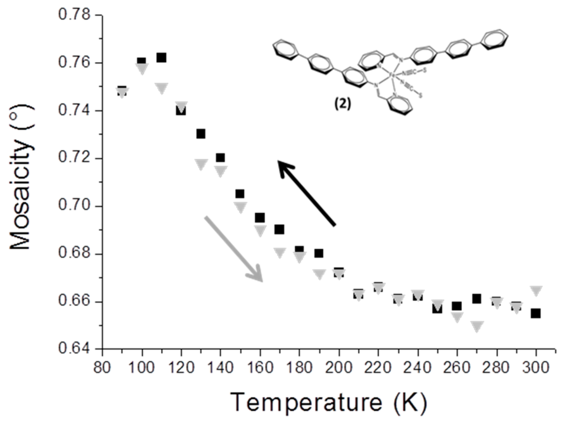
3.3. Mosaicity and Incomplete SCO in [Fe(PM-TeA)2(NCS)2]·0.5MeOH (2)
The compound [Fe(PM-TeA)2(NCS)2]·0.5MeOH is known to undergo an incomplete (about 60%) and gradual SCO, taking place mainly in the range of 200−90 K [11]. The mosaicity of the crystal increases when temperature decreases in the range 190−100 K (Figure 2); this is coherent with the SCO temperature range. The disorder due to the combination of HS and LS entities within the crystal is again revealed by the increase in mosaicity, which is fully reversible when the sample is warmed. Maximum mosaicity is observed at about 110 K, the temperature at which magnetic measurements show that half of the entities are LS within the crystal.
3.4. Mosaicity and Dynamical Disorder in [Fe(PM-TheA)2(NCS)2] (3)
The compound [Fe(PM-TheA)2(NCS)2] occurs in two polymorphs; the polymorph studied here undergoes a complete gradual SCO with T1/2 = 243 K [12]. From the structural point of view, the peculiarity of this compound is to exhibit strong atomic disorder affecting the thiophene rings (Scheme 1). The detailed description of this disorder is not the subject of this paper. Suffice it to say that the disorder has two components, the one being statistical, the other dynamical. The dynamical contribution therefore significantly decreases with temperature, notably in the 300–100 K temperature range. The mosaicity of the crystal decreases almost continuously from 300 to 100 K (Figure 3), with no apparent sign of SCO. The decrease of mosaicity is also perfectly reversible by warming.
As explained above, the mosaicity in question comes from the measurement of M that accounts for all kind of defects in the crystal which affect the width of the Bragg peaks. Any reduction in dynamical disorder leads to a drop in the M value. Our results show that the change in mosaicity is low and that the part due to the SCO is totally masked by the drop in dynamical atomic disorder.
3.5. Mosaicity and Mechanical Fatigability in [Fe(PM-PeA)2(NCSe)2] (4)
The compound [Fe(PM-PeA)2(NCSe)2] has recently been reported; it is one of the very few compounds exhibiting SCO at room temperature together with a large hysteresis (T1/2down = 266 K and T1/2up = 307 K) [13]. As with sulphur, [Fe(PM-PeA)2(NCS)2] [11], this compound undergoes a highly cooperative phase transition associated with SCO and characterized by relatively distinct HS and LS crystal packings. Its mosaicity increases strongly and abruptly when cooling at about 260 K (Figure 4). The initial mosaicity (<0.7°) reflects the good crystalline quality of the sample in the HS state. In the LS state, below 250 K, its unusually high mosaicity (>4.0°) shows the marked degradation in crystal quality. There is no significant change in mosaicity upon further cooling from 250 to 100 K, clearly linking this loss of quality to the SCO. The loss of crystal quality is not reversible; there is no return of mosaicity to its initial value and there is even a tendency for the crystal to crack if warmed.
Although reproducible, this phenomenon varies from one crystal to another; the drop in mosaicity and level of cracking depend on sample size. Cooling time may also be relevant; cooling was very slow in this study. These observations deserve further investigation. It is nevertheless clear that SCO degrades the sample through a form of mechanical fatigability, as already observed in other SCO materials [16,17]. It can be noted that there are no significant effects of this mechanical degradation on the magnetic characterization of the SCO, since the magnetic curve is not affected by repeated cycles [13]. It is interesting from the methodological point of view that SCO can also be tracked by the temperature dependence of the mosaicity in this compound.
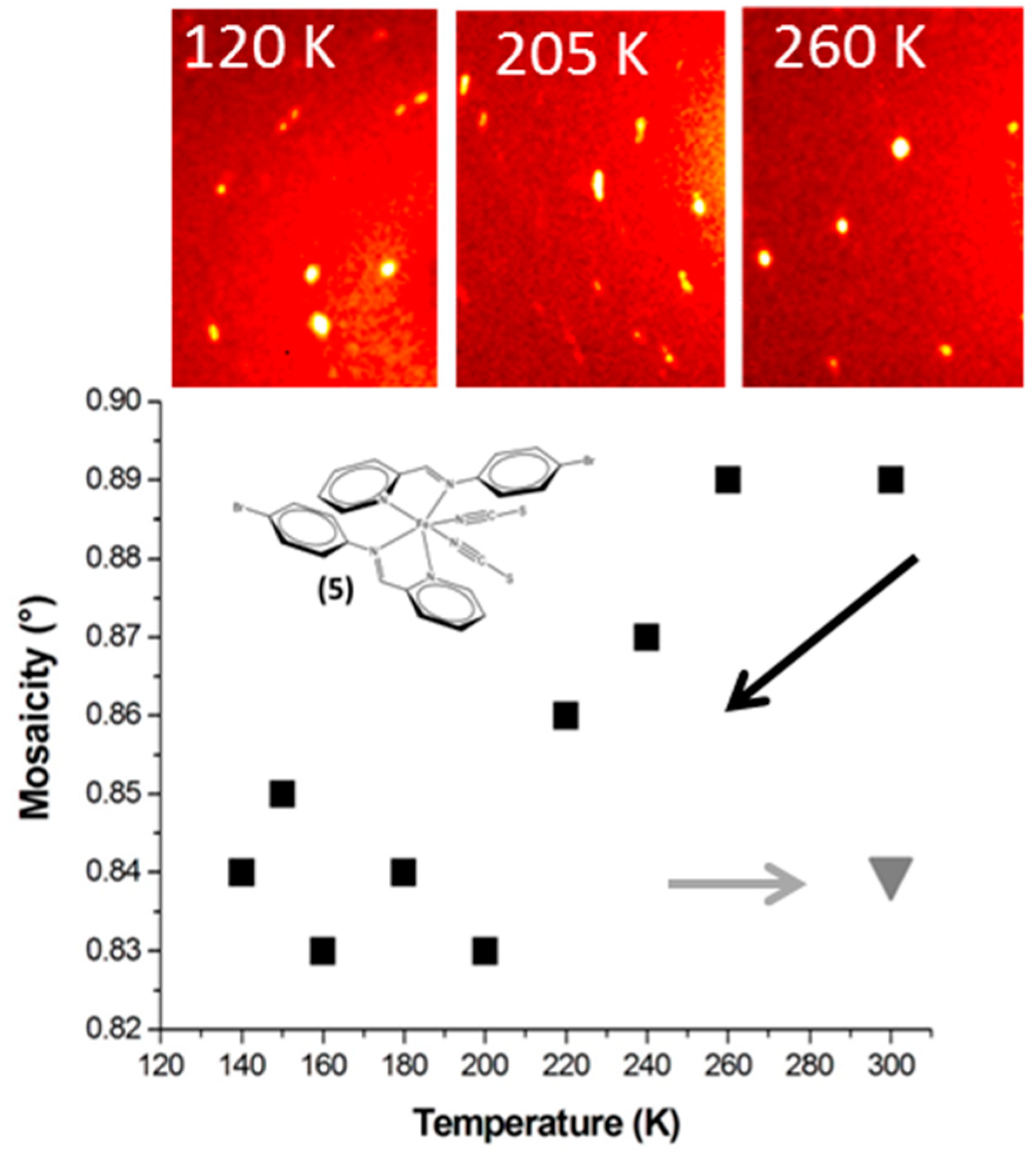
3.6. Pitfalls with the Mosaicity Approach: [Fe(PM-BrA)2(NCS)2] (5)
The compound [Fe(PM-BrA)2(NCS)2] is a newly synthetized complex identified as a source of polymorphism; details on its behaviour are being published elsewhere [15]. Here we focus on the mosaicity of one polymorph undergoing abrupt SCO at T1/2 ~210 K. Its mosaicity slightly decreases with temperature, the fact that the high temperature values are in the HS area would indicate better crystal quality after SCO (Figure 5). The improvement appears to be irreversible, since mosaicity remains lower with the return to room temperature (HS).
This is contradicted by the diffraction images however. The quality of the crystal seems to have been affected by the SCO and extra peaks appear at 120 K, suggesting a crack in the sample. Note that part of the sample is HS at 205 K and another part at LS, giving a number of double peaks which prevent any reliable measurement of M. At 120 K all the peaks may be indexed by the LS unit cell; there is no sign of HS residue, but the twin peaks indicate that the crystal has clearly suffered from the SCO probably due to cracks. These cracks are irreversible. After the SCO cycle the diffraction pattern at 300 K is similar to that at 120 K—i.e., worse than at 300 K before any temperature treatment.
The value of M here does not reflect such degradation, since it is calculated for only one component, allowing a maximum number of peaks to be indexed. Other peaks are not taken into account in calculating the value of M. The mosaicity measured is therefore only true for one part of the sample and does not reflect its quality. The damage to the crystal occurs at an larger physical scale as it separates into different coherent domains. Within these coherent domains, however, crystal quality seems to improve slightly at low temperature. It can therefore be concluded that, for this compound, the measurement of mosaicity as we have defined it does not provide an efficient account of SCO-induced crystal degradation. This result illustrates one of the limits of the mosaicity investigation as reported here. Note also that we have no clear explanation on the difference of behavior between compounds 4 and 5 since they both show abrupt transitions but diverge in their mosaicity temperature dependence.
4. Discussion and Conclusions
The results described above for compounds 1–5 illustrate the diversity of situations encountered when dealing with spin crossover in molecular crystals. In all these studies the consistency of the series of values validates the experimental protocol.
Compounds 1 and 2 generally meet the initial expectations in term of temperature dependence of the mosaicity during a gradual SCO. In the temperature range where the sample shows both HS and LS, the significant increase in mosaicity was expected; it allows the SCO to be followed notably by determining the temperature at which half of the entities commute. Incidentally, this approach provides a new way to determine the so called T1/2 experimentally.
Compound 3 exemplifies how a parameter other than mosaicity can affect the M value, hiding the effect of SCO on mosaicity. This is also true for compound 2 (crystals larger than the crystal in our study do not behave in the same way) and of compound 4 (for which the amplitude of mosaicity variation is dependent on crystal size). This highlights the need for caution when interpreting temperature-dependent mosaicity in spin-crossover crystals.
In parallel, the study of compound 4 shows the potentiality of this approach since it clearly highlights the mechanical fatigability that can occur in crystals undergoing abrupt SCO. This is probably an important point for the development of mechanical devices based on spin-crossover crystals [18] and of molecular switches or bending crystals more generally [19].
The case of compound 5 confirms that mosaicity changes may occur at the limits of experimental sensitivity. More importantly, it shows that the measurement of mosaicity through M does not necessarily capture all aspects of crystal quality. For instance, the true evolution of M is more easily identified when SCO occurs without domain formation. The increase in M should result from the distortion of the HS lattice by the presence of LS molecules, rather than through the misalignment of domains. We know, however, that, under SCO with domain formation, higher M values can occur even if the domain shows no defect or misalignment, due to the partial overlap of Bragg peaks of both domains. In this case it is difficult to obtain the true value of M for both domains unless both domains can be indexed separately.
The present study once again demonstrates that SCO on real crystals is a subtle and complex phenomenon involving a large number of parameters on different physical scales; some of these parameters are sample dependent. It would consequently be difficult, if not vain, to pronounce on general relationships between mosaicity and SCO behaviour. The temperature-dependence mosaicity approach developed in this paper nevertheless provides a tool which, if handled with care on a case-by-case basis, could shed new light on spin-crossover crystals, and on their potential mechanical fatigability in particular.
Supplementary Materials
The following are available online at https://www.mdpi.com/2073-4352/8/9/363/s1, Figure S1. Mosaicity of the crystal test as a function of the crystal-detector distance; Figure S2. Mosaicity of the crystal test as a function of the angular oscillation width; Figure S3. Mosaicity of the crystal test as a function of data collection resolution (Å); Figure S4. Mosaicity of the crystal test as a function of frame exposure time (s/°); Figure S5. Mosaicity of the crystal test as a function of temperature; Table S1. Mosaicity of the crystal test as a function of collimator diameter (mm).
Author Contributions
All authors contributed equally to the work.
Acknowledgments
S.L., F.L. and E.T. were funded by the French Ministry of Research through a PhD grant. W.G.’s PhD is funded by the China Scholarship Council (CSC). The authors gratefully acknowledge the Agence Nationale de la Recherche for its financial support under grant ANR FemtoMat 13-BS046002, and the Région Nouvelle Aquitaine. Robert CORNER (ILL) is thanked for his very meticulous correction of the English language.
Conflicts of Interest
The authors declare no conflict of interest.
References
- Darwin, C.G. The theory of X-ray reflection. Philos. Mag. 1922, 43, 800–829. [Google Scholar] [CrossRef]
- Bragg, W.H. The intensity of reflection of X-rays by crystals. Philos. Mag. 1926, 1, 897–922. [Google Scholar] [CrossRef]
- Bragg, W.L.; Nye, J.F. A dynamical model of a crystal structure. Proc. R. Soc. Lond. A 1947, 190, 474–481. [Google Scholar] [CrossRef] [Green Version]
- Goeta, A.E.; Howard, J.A.K. Low temperature single crystal X-ray diffraction: Advantages, instrumentation and applications. Chem. Soc. Rev. 2004, 33, 490–500. [Google Scholar] [CrossRef] [PubMed]
- Bellamy, H.D.; Snell, E.H.; Lovelace, J.; Pokross, M.; Borgstahlc, G.E.O. The high-mosaicity illusion: Revealing the true physical characteristics of macromolecular crystals. Acta Crystallogr. Sect. D 2000, 56, 986–995. [Google Scholar] [CrossRef]
- Guionneau, P. Crystallography and spin-crossover. A view of breathing materials. Dalton Trans. 2014, 43, 382–393. [Google Scholar] [CrossRef] [PubMed]
- Collet, E.; Guionneau, P. Structural analysis of spin-crossover materials: From molecules to materials. C. R. Chim. 2018, in press, proof on line. [Google Scholar] [CrossRef]
- Guionneau, P.; Lakhloufi, S.; Lemée-Cailleau, M.H.; Chastanet, G.; Rosa, P.; Mauriac, C.; Létard, J.F. Mosaicity and structural fatigability of a gradual spin-crossover single crystal. Chem. Phys. Lett. 2012, 542, 52–55. [Google Scholar] [CrossRef]
- Pittala, M.; Thétiot, F.; Triki, S.; Boukheddaden, K.; Chastanet, G.; Marchivie, M. Cooperative 1D triazole-based spin crossover FeII material with exceptional mechanical resilience. Chem. Mater. 2017, 29, 490–494. [Google Scholar] [CrossRef]
- Lakhloufi, S.; Lemee-Cailleau, M.H.; Chastanet, G.; Rosa, P.; Daro, N.; Guionneau, P. Structural movies of the gradual spin-crossover in a molecular complex at various physical scales. Phys. Chem. Chem. Phys. 2016, 18, 28307–28315. [Google Scholar] [CrossRef] [PubMed]
- Guionneau, P.; Létard, J.F.; Yuffit, D.S.; Chasseau, D.; Goeta Bravic, A.E.; Howard, J.A.K.; Kahn, O. Structural approach of the features of the spin crossover transition in iron(II) compounds. J. Mater. Chem. 1999, 9, 985–994. [Google Scholar] [CrossRef]
- Marchivie, M. Approche structurale du phénomène de transition de spin par diffraction des rayons X sous contraintes (T, P, hv). Ph.D. Thesis, University of Bordeaux, Bordeaux, France, 25 November 2003. [Google Scholar]
- Tailleur, E.; Marchivie, M.; Daro, N.; Chastanet, G.; Guionneau, P. Thermal spin-crossover with a large hysteresis spanning room temperature in a mononuclear complex. Chem. Commun. 2017, 53, 4763–4766. [Google Scholar] [CrossRef] [PubMed]
- Otwinowski, Z.; Minor, W. Methods in Enzymology. In Macromolecular Crystallography, Part A; Carter, C.W., Sweet, R.M., Eds.; Academic Press: New York, NY, USA, 1997; Volume 276, pp. 307–326. [Google Scholar]
- Guo, W.; Chastanet, G.; Guionneau, P. Polymorphism in the spin crossover [Fe(PM-BrA)2(NCS)2] compound. J. Mater. Chem. C 2018. submitted. [Google Scholar]
- Craig, G.A.; Sánchez Costa, J.; Roubeau, O.; Teat, S.J.; Aromí, G. An FeII spin-crossover complex becomes increasingly cooperative with ageing. Eur. J. Inorg. Chem. 2013, 5–6, 745–752. [Google Scholar] [CrossRef]
- Manrique-Juárez, M.D.; Suleimanov, I.; Hernández, E.M.; Salmon, L.; Molnár, G.; Bousseksou, A. In situ AFM imaging of microstructural changes associated with the spin transition in [Fe(htrz)2(trz)](BF4) nanoparticles. Materials 2016, 9, 537. [Google Scholar] [CrossRef] [PubMed]
- Shepherd, H.J.; Gural’skiy, I.A.; Quintero, C.M.; Tricard, S.; Salmon, L.; Molnár, G.; Bousseksou, A. Molecular actuators driven by cooperative spin-state switching. Nat. Commun. 2013, 4, 2607. [Google Scholar] [CrossRef] [PubMed] [Green Version]
- Naumov, P.; Chizhik, S.; Panda, M.K.; Nath, N.K.; Boldyreva, E. Mechanically responsive molecular crystals. Chem. Rev. 2015, 115, 12440–12490. [Google Scholar] [CrossRef] [PubMed]
Scheme 1.
schematic views of the molecular iron(II) complexes of the [FeII(PM-L)2(NCX)2] series studied in this paper, labelled 1 to 5.
Scheme 1.
schematic views of the molecular iron(II) complexes of the [FeII(PM-L)2(NCX)2] series studied in this paper, labelled 1 to 5.
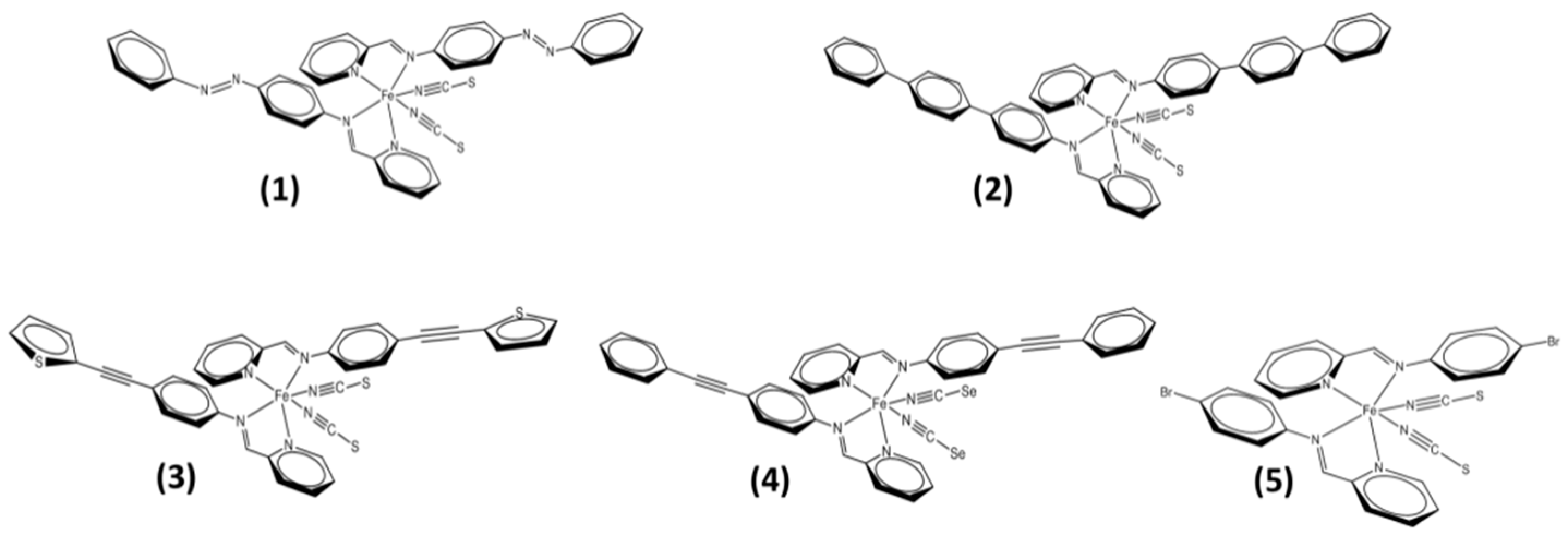
Figure 1.
Temperature dependence of the mosaicity for a small crystal of [Fe(PM-AzA)2(NCS)2] in the cooling mode.
Figure 1.
Temperature dependence of the mosaicity for a small crystal of [Fe(PM-AzA)2(NCS)2] in the cooling mode.
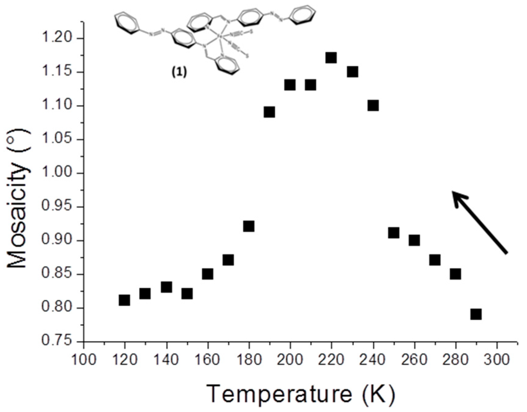
Figure 2.
Temperature dependence of the mosaicity for a crystal of [Fe(PM-TeA)2(NCS)2]·0.5MeOH in the cooling (black squares) and warming (grey triangles) modes.
Figure 2.
Temperature dependence of the mosaicity for a crystal of [Fe(PM-TeA)2(NCS)2]·0.5MeOH in the cooling (black squares) and warming (grey triangles) modes.

Figure 3.
Temperature dependence of the mosaicity for a crystal of [Fe(PM-TheA)2(NCS)2]-II in the cooling (black squares) and warming (light-grey triangles) modes.
Figure 3.
Temperature dependence of the mosaicity for a crystal of [Fe(PM-TheA)2(NCS)2]-II in the cooling (black squares) and warming (light-grey triangles) modes.
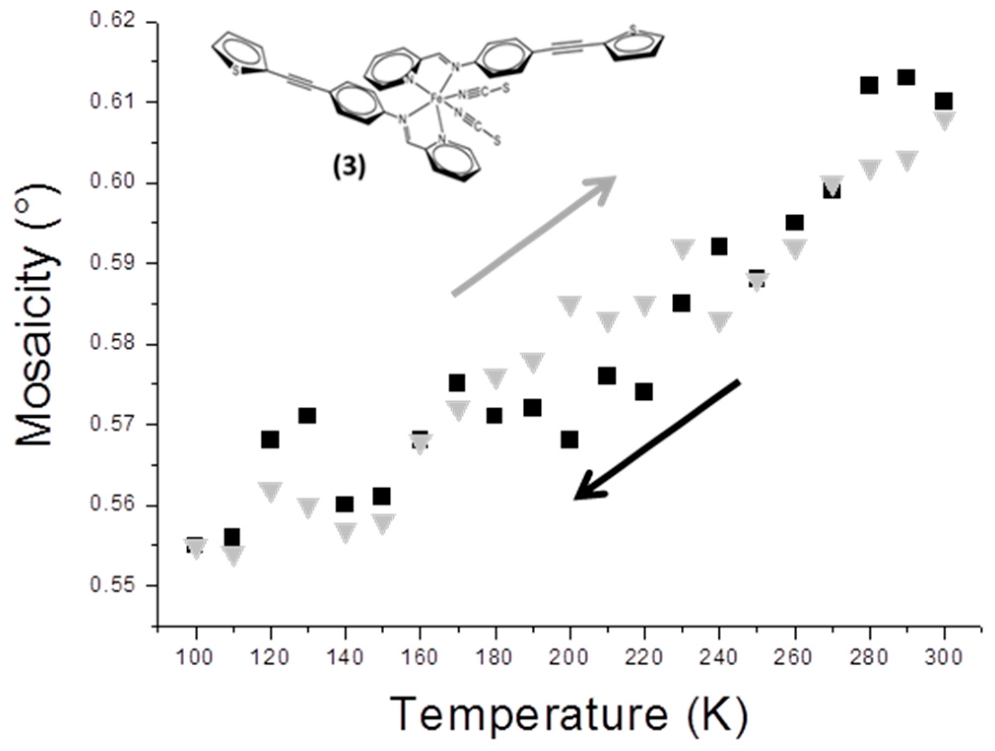
Figure 4.
Temperature dependence of the mosaicity of [Fe(PM-PeA)2(NCSe)2] in the cooling mode (black squares), including the return values (light grey) after warming at room temperature.
Figure 4.
Temperature dependence of the mosaicity of [Fe(PM-PeA)2(NCSe)2] in the cooling mode (black squares), including the return values (light grey) after warming at room temperature.
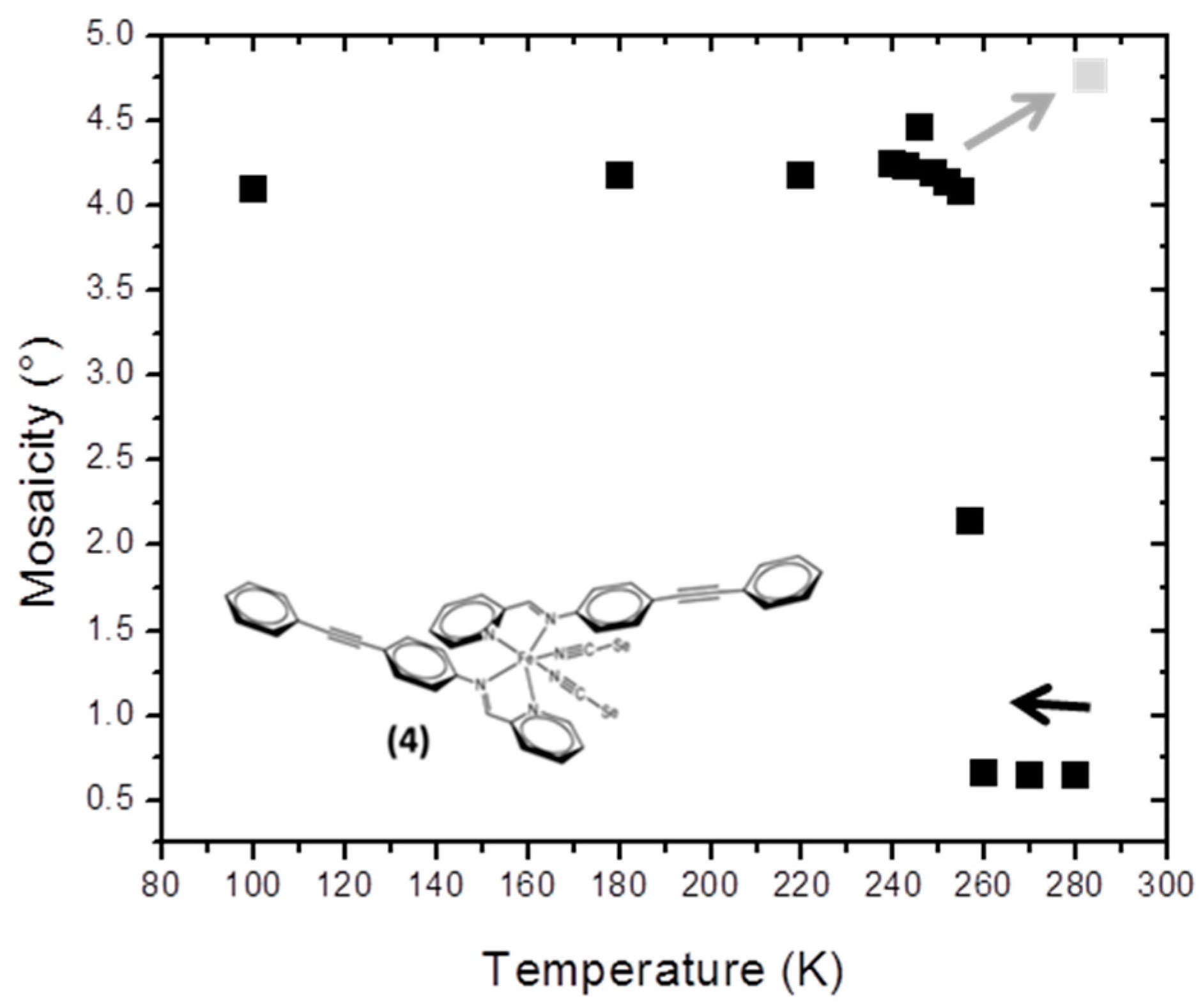
Figure 5.
Temperature dependence of the mosaicity of [Fe(PM-BrA)2(NCS)2] in the cooling mode, with diffraction images at 120 K (LS), 205 K (mixture HS/LS) and 260 K (HS). Full squares mark the cooling mode and the grey triangle the value when returned to room temperature.
Figure 5.
Temperature dependence of the mosaicity of [Fe(PM-BrA)2(NCS)2] in the cooling mode, with diffraction images at 120 K (LS), 205 K (mixture HS/LS) and 260 K (HS). Full squares mark the cooling mode and the grey triangle the value when returned to room temperature.

© 2018 by the authors. Licensee MDPI, Basel, Switzerland. This article is an open access article distributed under the terms and conditions of the Creative Commons Attribution (CC BY) license (http://creativecommons.org/licenses/by/4.0/).
Share and Cite
MDPI and ACS Style
Lakhloufi, S.; Tailleur, E.; Guo, W.; Le Gac, F.; Marchivie, M.; Lemée-Cailleau, M.-H.; Chastanet, G.; Guionneau, P. Mosaicity of Spin-Crossover Crystals. Crystals 2018, 8, 363. https://doi.org/10.3390/cryst8090363
AMA Style
Lakhloufi S, Tailleur E, Guo W, Le Gac F, Marchivie M, Lemée-Cailleau M-H, Chastanet G, Guionneau P. Mosaicity of Spin-Crossover Crystals. Crystals. 2018; 8(9):363. https://doi.org/10.3390/cryst8090363
Chicago/Turabian StyleLakhloufi, Sabine, Elodie Tailleur, Wenbin Guo, Frédéric Le Gac, Mathieu Marchivie, Marie-Hélène Lemée-Cailleau, Guillaume Chastanet, and Philippe Guionneau. 2018. "Mosaicity of Spin-Crossover Crystals" Crystals 8, no. 9: 363. https://doi.org/10.3390/cryst8090363
Note that from the first issue of 2016, this journal uses article numbers instead of page numbers. See further details here.