Band Structures Analysis of Elastic Waves Propagating along Thickness Direction in Periodically Laminated Piezoelectric Composites


1
College of Urban and Rural Construction, Shanxi Agricultural University, Jinzhong 030801, China
2
School of Civil Engineering and Mechanics, Lanzhou University, and Key Laboratory of Mechanics on Disaster and Environment in Western China, Ministry of Education, Lanzhou 730000, China
*
Author to whom correspondence should be addressed.
Crystals 2018, 8(9), 351; https://doi.org/10.3390/cryst8090351
Submission received: 18 July 2018
/
Revised: 12 August 2018
/
Accepted: 20 August 2018
/
Published: 1 September 2018
(This article belongs to the Special Issue Phononics)
Abstract
:Existing studies on elastic waves in periodically laminated piezoelectric structures mainly concerned the passive band properties, since the electrical boundaries in the considered structures cannot vary. This paper investigates the tuning of band properties of uncoupled primary and shear (P- and S-) waves along the thickness direction by actively varying the electrical field in periodically multilayered piezoelectric structures consisting of orthotropic materials. The alteration of the electrical field is realized in the multilayered unit cell here by either applying or switching four kinds of electrical boundary conditions, including the electric-open, applied electric capacitance, electric-short, and applied feedback voltage, to the constituent piezoelectric layer via the constituent electrode layers covering both its surfaces. First, the state space formalism is introduced to obtain the partial wave solution of any constituent orthotropic layer in the unit cell. Second, the traditional transfer matrix method is adopted to derive the dispersion equation of general, periodically laminated piezoelectric composites with unit cells consisting of an arbitrary number of piezoelectric layers with various boundaries and of elastic layers. Third, numerical examples are provided to verify the proposed analysis method, and to study the influences of electrode thickness as well as four electrical boundaries on the band structures. All the frequency-related dispersion curves are also illustrated by numerical examples to summarize the general dispersion characteristics of uncoupled P- and S-waves in periodically laminated piezoelectric composites. The main finding is that the innovative dispersion characteristic resulting from the negative capacitance may also be achieved via feedback control.
1. Introduction
Periodically laminated composites consist of repeatedly arranged material layers with different acoustic properties [1,2,3,4,5,6,7]. As a typical kind of periodic structure, periodically laminated composites possess elastic-wave band properties, i.e., the elastic wave with frequencies in the bandgap attenuates quickly without propagation, and the elastic wave with frequencies in the passband propagates without attenuation [7,8]. This elastic-wave band behavior is similar to the De-Broglie wave in electronic crystals [8,9,10] and the electromagnetic wave in photonic crystals [11,12,13]. In order to develop the applications of band property in filter manufacture, non-destructive testing, signal transmission, etc., the elastic wave propagation in periodically laminated composites has attracted a lot of attention in the last few decades [1,2,3,4,5,6,7,14,15,16].
However, with the tremendous progress of information science and electronic technology in the recent decades, the elastic-wave frequency bands in normally designed and traditionally used periodically laminated elastic structures can not satisfy the higher-performance demand. There are two ways for catering this severe requirement. The one way is to optimize the configuration of unit cell in periodically laminated elastic composites, so that the width and location of bandgaps exactly satisfy the required objective. Following this idea, Sigmund and Jensen [17] discussed the topology optimization for both out-of-plane and in-plane waves in order to achieve maximal width and minimal central frequency of bandgap; Hussein et al. [18] and EI-Beltagy [19] optimized the longitudinal-wave bands according to multiple objectives, by genetic algorithm and evolutionary search, respectively. The disadvantage of this way is that the width and location of frequency band are fixed after optimization and they satisfy the requirement passively. Thus, this scheme can not realize frequency bands that adapt to changing environment. The other way is to introduce hyperelastic or smart material as the constituent layer in the periodically laminated structures so that the elastic-wave bands may be controlled actively through deformation/instability or various physical other than mechanical fields. So far, the following four kinds of materials have been introduced. First, with involving soft hyperelastic layer, Galich et al. [20] tuned the shear and pressure wave bandgaps by deformation and found highly tunable complete bandgaps in low-frequency ranges can be achieved; but Zhang and Parnell [21] tried to freeze the elastic-wave bands also through deformation; Slesarenko et al. [22] and Li et al. [23] both investigated the instability induced tunability of the widths and locations of pressure and shear wave bandgaps, and the former [22] found the appearance of omni-directional negative group velocity that foreshadows microscopic loss of the stability as well as the latter [23] obtained the complete band gaps through deformation in both stable and post-buckling regimes. Note that the tuning of band property by deformation or instability in mechanical field needs considering the geometrical nonlinearity of the periodically laminated system with hyperelastic layers. Second, using materials having the temperature-related phase transformations, Cheng et al. [24] and Li et al. [25] investigated the tuning of Lamb-wave and P- and SH-waves bandgaps through temperature field when ferroelectric ceramic Ba0.7Sr0.3TiO3 constituent layer and interfacial adhesive layer dependent on temperature were introduced, respectively. Third, by importing the dielectric elastomer layer, Galich and Rudykh [26] analyzed the manipulation of shear-wave bandgaps by finite deformation or electrostatically induced deformation; Wu et al. [27] studied the tuning of the defect longitudinal-wave bands by applying an electric voltage; Bortot et al. [28] performed topology optimization using genetic algorithm approach for widening the SH (horizontally shear) wave bandgaps and improving their tunability to electrostatically-controlled deformations.
Besides the above-mentioned three introduced materials, another smart material, which is the fourth introduced material, is the piezoelectric material, which is also dependent on electric fields like the dielectric elastomer, which has been extensively used in periodically laminated structures, i.e., one-dimensional (1D) piezoelectric layered phononic crystals. Because the electrical field is relatively easy to control and the piezoelectric effect is linear coupling between the electrical and mechanical fields, the elastic wave propagation and its tuning by the electrical conditions in periodically laminated piezoelectric composites have received extensive attention during the last two decades [29,30,31,32,33,34,35,36,37,38,39,40,41,42,43,44,45,46,47,48]. The earlier literatures on this topic only considered the relatively simple electrical boundaries, i.e., the electric-open and electric-short conditions. In these literature, the horizontally shear (SH) wave was investigated sufficiently. Minagawa [29] initiated the analysis of SH-wave propagation in 1D periodically laminated piezoelectric composites in 1995. Then, in 2004, Qian et al. [30] produced a deeper analysis of the same topic and obtained general solutions for SH-wave in periodic bi-layered materials. Later, Li et al. [31] investigated the propagation and localization characteristics of SH waves in randomly disordered, periodically laminated piezoelectric composites. Recently, Zhao et al. [32,33] studied the propagation of the SH wave in the periodically single piezoelectric layer and multilayered piezoelectric structure with the piezoelectricity considered or neglected. Besides, many researchers did extension studies on other kinds of elastic waves in periodically laminated piezoelectric structures. For examples, Li et al. [34,35,36,37] discussed the propagation and localization of in-plane (P-SV) waves and Rayleigh waves in disordered, periodically laminated piezoelectric structures. Lan et al. [38] investigated the dispersive characteristics of elastic waves propagating through laminated piezoelectric phononic crystals with imperfect interfaces and discussed the influence of the imperfect interface on dispersion curves/bandgaps. Zou et al. [39] studied theoretically the band structures of plate-mode (Lamb) waves in the 1D phononic crystal plate consisting of piezoelectric ceramics placed periodically in an epoxy substrate and found that the width of first bandgap associated with the electric-short condition is always larger than that corresponding to the electric-open boundary in the case of the same polarization.
As can be seen from the above literature review, although the electric-open and electric-short boundaries are easy to apply, they provide very limited modulation (just two cases) to the frequency band property for periodically laminated piezoelectric structures. Naturally, in recent years the tunable electric components have been introduced to achieve continuously varying electrical boundaries. By so doing, the frequency band property of periodically laminated piezoelectric structures can be tuned continuously within certain ranges. These introduced tunable components contain electrical impedance, capacitance, voltage, and inductance. By adopting the electrical impedance condition, Mansoura et al. [40,41] investigated theoretically and experimentally the bandgap control of elastic waves perpendicular to the layers and found that the change of electric impedance can be used to obviously modify the band structure and acoustic transmission. When considering the applied capacitance, Mansoura et al. [42] also proposed the use of negative capacitance values to achieve unusual band properties. Kutsenko et al. [43,44] successively investigated the tuning of bandgap characteristics of longitudinal waves perpendicular to layering in layered phononic crystals, whose piezoelectric layers are connected to external capacitance. This is equivalent to homogeneous material whose parameters depend on piezoelectric and dielectric coefficients of piezoelectric materials in the case of positive capacitance. In the case of negative capacitance, the dimensionless imaginary wavenumber () spectra have poles, at whose corresponding frequency in stopbands the phase constant () jumps from to . Besides, Kutsenko et al. [45] investigated the dispersion spectrum of the longitudinal acoustoelectric wave in the piezoelectric crystals coupled with the electric wave of potentials and charges in the network of capacitors and found that the dispersion spectrum consists of a discrete set of curves when capacitance and are of same sign. The spectrum simultaneously includes the discrete set of dispersion curves and the continuous bands when capacitance and are of the opposite sign and . Ponge et al. [46] found that piezoelectric phononic crystals have Bragg bandgap under periodically electric short-condition and found out design scheme for Fabry-Perot cavity. By applying external voltage, Wang et al. [47] found that the thickness of inserted PMN-0.38PT layer predominantly relates to its strain coefficient that can be adjusted. By introducing an inductor, Zhu et al. [48] found that an extremely narrow stop band was caused.
Although the above-reviewed studies provide plenty of knowledge of elastic waves in general, periodically laminated piezoelectric composites, to our best knowledge the following four aspects of pending problems, however, have seldom been discussed: (1) The modulation of the primary (longitudinal) wave by the electrical tunable boundaries has been studied, but few investigations have dealt with the modulation of the shear (transversal) wave by these electrical boundaries. (2) The mechanical vibration of the electrodes is neglected by nulling their thickness without understanding their influence. (3) The connection and difference of the influences of the applied feedback control and of the applied electric capacitance on the frequency band property are not known. (4) The wave dispersion property has been solely represented by the frequency-wavenumber dispersion curve. However, other forms of dispersion curves such as the frequency-wavelength and frequency-phase velocity spectra may also be vital to representing wave dispersion properties from different perspectives.
This paper, which aims to solve the above-mentioned four pending problems, is organized as follows. In Section 2, the basic model of elastic waves including both primary (P-) and shear (S-) waves in general, periodically laminated piezoelectric composites with unit cells consisting of arbitrary numbers of piezoelectric layers with various boundaries and of elastic layers is described concisely. Section 3 introduces the state space formalism [49] in detail to obtain the partial wave solution of any constituent orthotropic layer in the unit cell. In Section 4, the dispersion equation of the elastic wave in the general model is derived on the basis of the transfer matrix method [50] combined with the Floquet-Bloch principle [7,8,51]. Section 5 gives numerical examples for decoupled P- and S-waves in periodically Glass-Brass-(PZT-5H)-Brass piezoelectric composites with Brass layers as electrodes. After the proposed formulation is validated by comparing the results with counterpart results in literature and by other methods, the influence of electrode thickness and electrical boundaries including the electric-open, applied electric capacitance, electric-short, and applied feedback voltage on dispersion properties is studied in detail. The general properties of frequency-related dispersion curves are also summarized through the analysis of results from the numerical example. Conclusions based on these studies are drawn in Section 6.
2. Basic Model
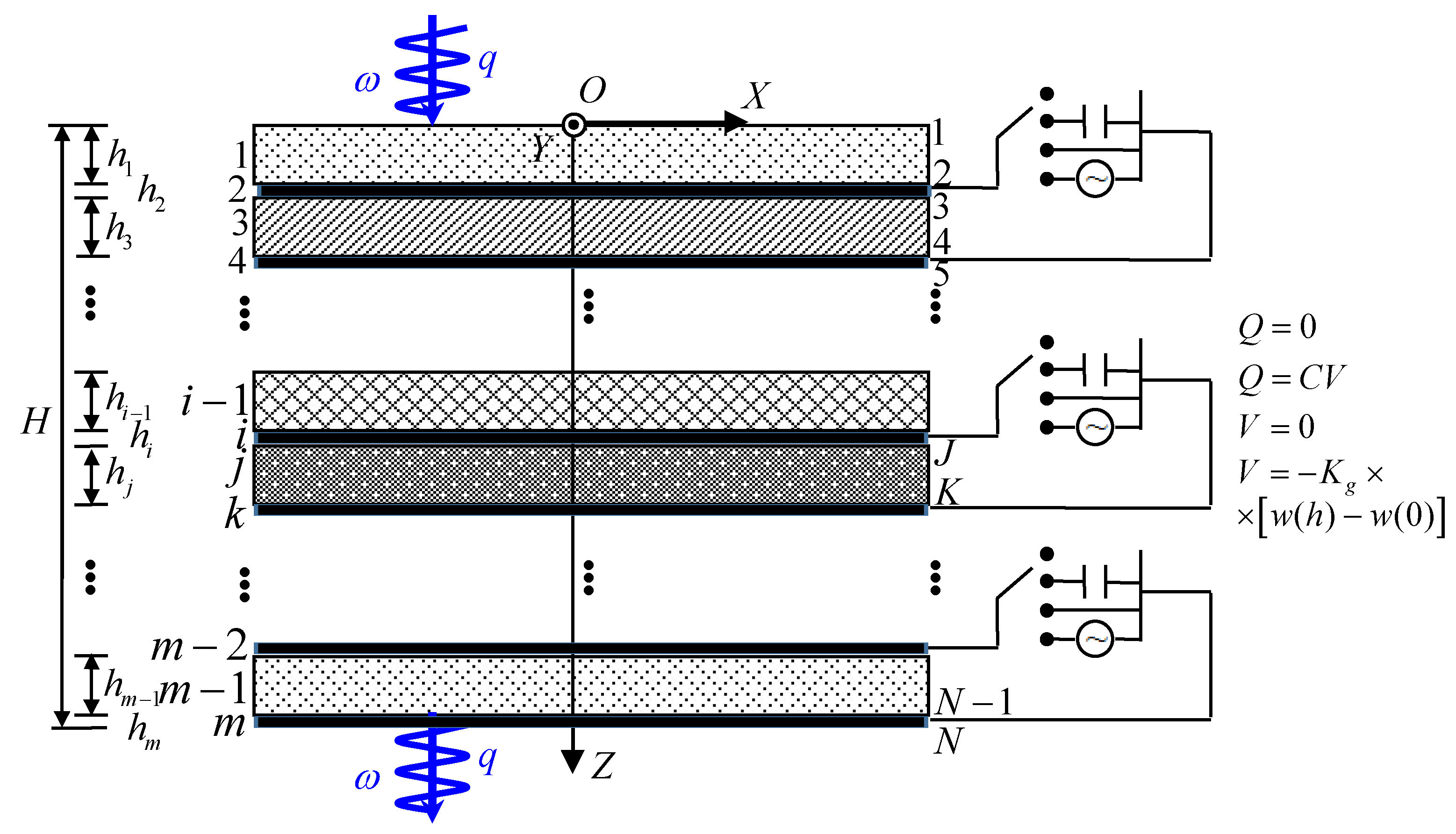
Consider elastic waves along the thickness direction in general periodically laminated piezoelectric composites with the unit cell consisting of all together (arbitrary number) piezoelectric and elastic layers and being shown in Figure 1. The thickness of any constituent layer is much smaller than its in-plane dimensions, so it is treated here as boundary-less in the layer plane. If the electrical boundaries other than the electric-open condition, including the applied electric capacitance (with capacity ), electric-short and applied feedback control (with the gain coefficient ) conditions, are needed to apply on any of the piezoelectric layers to tune its electrical and mechanical fields, a pair of electrodes must be coated on the top and bottom surfaces of that piezoelectric layer. By switching or modulating these four electrical boundaries via the electrodes, with their governing mathematical formulas listed in Table 1, the dispersion characteristics of the elastic waves along the thickness direction can be tuned. These electrodes with the in-plane area , are also modeled as the elastic layers in Figure 1, if their mechanical effects are also considered. All the adjacent constituent layers are perfectly connected at the interfaces. All the piezoelectric layers and the elastic layers (including both the electrodes and the inserted elastic layers) are all assumed as orthotropic materials or materials with higher symmetry. It can be inferred that, from the relation between the macro-physical properties and the crystal class [52,53], the mechanical/electrical properties of materials with higher crystal symmetry than the orthotropic materials can be deemed as the special cases of the latter, while some stiffness/dielectric constants are identical and some piezoelectric constants are zero. Therefore, in the following Section 3 the derivations of the state equation of any constituent layer and its wave solution are all based on the orthotropic materials of crystal classes , , and [52,53]. The derived result also indicates that the three mechanical wave modes propagating along the thickness direction are decoupled. Thus, the effect of electrical boundaries on the dispersion characteristics of decoupled primary (P-) and shear (S-) waves can be studied. If elastic waves along the direction oblique to the thickness are considered, they can not be decoupled into three pure P- and pure S-waves. Then the dispersion characteristics of these oblique elastic waves may be much more complex than the results provided in this paper, which will be considered in a future study. Interested readers can refer to Ref. [54] for detailed discussions on oblique shear waves in periodically laminated composites with hyperelastic layers of finite deformation.
Due to the Floquet-Bloch theorem for periodic structures [7,8,51], the decoupled P- and S-waves along the thickness direction in the considered periodically laminated piezoelectric composites can be analyzed on the basis of only one unit cell, whose schematic is depicted in Figure 1. The dispersion of the elastic waves is mainly represented by the characteristic wavenumber along the thickness direction and the circular frequency . For the convenience of description, a global right-handed coordinate system is established with its origin being located on the top surface of the current unit cell and the axis pointing to the thickness and downward direction. All the constituent layers including electrodes, are numbered in succession along the axis from to with their thickness denoted by through . The total thickness of the unit cell is . The interfaces, including the top and bottom surfaces, are denoted in succession from top to bottom along the axis by to .
3. State Space Formalism
3.1. Equations Governing the Elastodynamics of a Layer
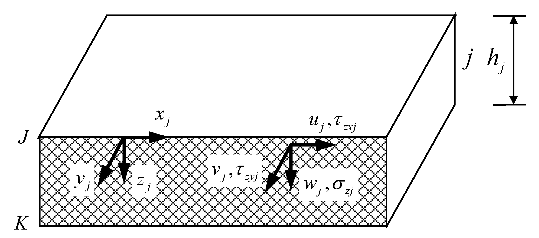
For any constituent layer of either piezoelectric or elastic material in the unit cell, say layer described in its local right-handed coordinate system as shown in Figure 2, the three-dimensional (3-D) elastic theory governing its elastodynamics [52,53] is represented by the geometric relations, the constitutive equations, and the equations of motion together with the Gauss’s law of electrostatics. During the following derivation in this section, the subscript is omitted for brevity.
Substituting the generalized geometric relations
into the constitutive equations of piezoelectric material or the constitutive equations of elastic material (such as electrode or other elastic constituent layer)
one obtains the relation between the generalized stresses and the generalized displacements
of piezoelectric or elastic material, respectively. In Equations (1) to (3), and are the mechanical displacement vector and the electric potential scalar, respectively, which are combined to form the generalized displacements. and are the mechanical strain and electric field intensity vectors, respectively. and are the stress and electric displacement vectors, respectively, which are combined to form the generalized stresses. and are the matrix operator of dimension and the 3-D Hamilton operator in form of column vector, respectively, whose components are written explicitly as follows
Superscript “” denotes the transposition of a matrix or a vector. and are the symmetric stiffness constant matrix and the symmetric dielectric constant matrix, respectively, which express the mechanical and electrical properties of the layer, respectively. is the piezoelectric constant matrix, which represents the coupling property between mechanical and electrical fields. It should be zero matrix for non-piezoelectric material. For orthotropic material (crystal classes , , and ) considered in this paper, the components of and are uniformly given in Appendix A, while those of are respectively shown in Appendix B. Notice that the latter group of equations in Equations (2) and (3) for elastic layer can be regarded as a degeneration of the former group in Equations (2) and (3) for piezoelectric layer by neglecting the piezoelectric matrix. In the following derivation, we will bear this fact in mind and only emphasize the different cases of piezoelectric and elastic layers as needed.
The equations of motion (without body force) and the Gauss’s law of electrostatics of the considered layer are
respectively, where is the material density.
3.2. Derivation of the State Equation of a Layer
Equations (3) and (5) represent the complete correlation between the generalized stresses and the generalized displacements . Assume these physical variables have harmonic wave solutions in form of
where is the imaginary unit, and is the circular frequency. In Equation (6), and are the wavenumbers along the and directions, respectively, which are not explicitly appeared in the wave solution as indicated in the last formula since because only the elastic wave propagating along the thickness () direction is considered in this paper. Henceforth, the over caret “” indicates corresponding physical quantities in the domain. Because the in-plane dimensions are much larger than the thickness of the layer and the effect of the electric boundaries on the mechanical field is the main focus of this paper, the components of displacement state vector and stress state vector are chosen as the primary quantities, which are combined to form the state vector [49]. These basic physical variables of the typical layer are also depicted in Figure 2. Substitution of Equation (6) into Equations (3) and (5) respectively gives
where and are and matrices composed of partial components of stiffness and dielectric constant matrices and , respectively; and are and matrices composed of partial components of piezoelectric matrix . The concrete form of these matrices for orthotropic materials of crystal classes , , and can be referred to Appendix A and Appendix B. In the following, we will derive the state equation of the considered layer based on Equations (7) and (8) according to the two material types.
First, for piezoelectric layer covered with electrodes on its surfaces, the latter formula in Equation (8) indicates that is a constant, which relates to the electric charge on the overlaid electrodes by
with the area of electrodes. Note that is only used in the derivation here, but it does not need to be specified independently in the final calculation, because except the applied electric capacitance boundary, it will not be involved in the final formulation. Furthermore, in the applied electric capacitance condition, the capacitance per unit area is actually needed. Consequently, it is reasonable to assume that each constituent layer is boundary-less in the layer plane. Thus, should also be a constant. Substitute Equation (9) into the lower formula for piezoelectric material in Equation (7), which expresses as
with the matrix formed by the components in the last line of and provided in Appendix B for orthotropic crystal classes , , and , one obtains
which relates to the voltage (potential difference) between the electrodesby
Equation (12) provides the relation with respect to three quantities, i.e., the electric charge , the voltage , and the displacements difference . Various electrical boundaries actually either provide another relation between any two among these three quantities or specify directly anyone of and . This fact can be clearly demonstrated by the mathematical expressions corresponding to four electrical boundaries including the electric-open, applied electric capacitance, electric-short, and applied feedback voltage conditions listed in Table 2. Substitute Equation (12) into the mathematical expressions associated with various electrical boundaries, and can be expressed as formulas of or zero. Their expressions associated with the four electrical boundaries are also shown in Table 2. Then substituting the respective expression of into Equation (11) gives the expression of , which can be expressed uniformly for the four electrical boundaries as
with the matrix provided also in Table 2 for each of the four electrical boundaries. Further substitute Equation (13) into the formulas related to the stress state vector in Equation (7) for piezoelectric material as follows
then by combining like terms one derives the equations representing as
where is the matrix composed of the equivalent stiffness coefficients. Note that the mechanical stiffness, the piezoelectricity, and the dielectricity all affect the equivalent stiffness, and the material piezoelectricity actually strengthens the manifesting stiffness on the basis of mechanical stiffness. The combination of Equation (15) and the former formula in Equation (8) gives a set of inhomogeneous differential equations governing the state vector , which is referred to as the state equation. For the piezoelectric layers with considering the electrical boundaries studied here, the form of the state equation is as follows
where the coefficient matrices and corresponding respectively to the function and the inhomogeneous terms are composed of
with the third order identity matrix. Note that the form of is only related to the material crystal class, which is shown in Appendix C for the orthotropic materials of and crystal classes. Nevertheless, the form of is in connection with both the material crystal class and the electrical boundaries, which is displayed in Table A1 of Appendix C for the orthotropic materials of and crystal classes in combination with the four electrical boundaries including the electric-open, applied electric capacitance, electric-short and applied feedback voltage conditions. Since and are both diagonal matrices for these orthotropic materials, it can be deduced that the three mechanical wave modes including one primary (P-) mode and two shear (S-) modes are decoupled each other. For piezoelectric materials of crystal class with the various electrical conditions and of crystal class with the electric-open condition, is zero matrix indicates that in these cases the electrical boundaries do not influence on the mechanical wave propagation. For piezoelectric materials of crystal class with the plane perpendicular to , , and axes, the locations of the nonzero components in manifest that all the applied capacitance, electric-short and applied feedback control conditions merely affect the -polarized shear wave, -polarized shear wave and primary wave, respectively.
Second, for elastic layer modeling the electrodes and the inserted elastic layers, the combination of Equation (8) and the latter equation in Equation (7) gives
which indicates that the mechanical quantities () and are independent on the electrical quantities and . Since this paper concerns the effect of electrical quantities on the mechanical quantities, hence we only consider the former two formulas in Equation (18) that are related to the mechanical quantities. The second formula in Equation (18) determines the relation between the derivative of the displacement state vector and the stress state vector in form of
where the matrices and are identical for the elastic layer discussed here. From the comparison of Equation (19) with Equations (14) and (15), one notices that the quantities related to the electrical field, which are essential for piezoelectric layers, are vanishing for elastic layers. The combination of the latter equation in Equation (19) and the first equation in Equation (18) provides the state equation of elastic layers as follows
which are homogenous equations instead of inhomogeneous ones in Equation (16) for piezoelectric layer and where the coefficient matrix has the same form as that in Equation (17). Since and are both diagonal matrices for the orthotropic material of crystal class , it can be deduced that the three mechanical wave modes including one primary (P-) mode and two shear (S-) modes are decoupled each other, as also pointed out in the case of piezoelectric layer of and crystal classes. Note that Equation (20) can actually be degenerated from Equation (16) if the piezoelectric constants are zero. Consequently, the derivations henceforth are only based on Equation (16) for piezoelectric layers, and we should keep in mind that the results equally apply to Equation (20) for elastic layers as long as the piezoelectric constants are taken as zero.
3.3. Traveling Wave Solution of the State Equation for a Layer
The solution to the state equation can be obtained, according to the theory of inhomogeneous ordinary differential equations, in form of
where and are the diagonal eigenvalue matrix and the square eigenvector matrix of the coefficient matrix of state equation, respectively, both of dimension. If observed together with Equation (6), then the solution in Equation (21) can be deemed as the contribution summation of all partial waves on the state vector . The eigenvalues in are actually the wavenumbers of the partial waves, and the undetermined coefficients in vector are the partial wave amplitudes. Thus, the matrix exponential function and are essentially the phase function and the inhomogeneous phase term, respectively, with denoting the sixth order identity matrix here and after. The result of is a diagonal matrix of the same dimension as . Any component on its diagonal is computed from with the corresponding component of . The components in any row of denote the contribution coefficients of the partial waves on the state variable corresponding to that row. Based on that the components are corresponding to the displacement state vector and the stress state vector , is divided into two block matrices and . From the above, it is known that every quantity in the traveling wave solution of the state equation has clear physical meaning. The solution in Equation (21) also applies to the state equation of elastic layer, as long as zero piezoelectric coefficients are used during the computations of matrices and . Therefore, in the subsequent derivations, Equation (21) is directly referred without indicating that either a piezoelectric or an elastic layer is considering.
4. Transfer Matrix Method
After the state equation and its traveling wave solution of any constituent layer have been derived, we need to further integrate the dynamic states of all constituent layers of the unit cell in the dynamic state of the unit cell system. For this purpose, the classical transfer matrix method (TMM) [50], which is exceptionally efficient for chain systems like the multilayered structures considered here, is utilized to establish the governing equations of the unit cell system.
First, the dynamic state of any constituent layer is needed to be described from another viewpoint, i.e., from the viewpoint of the transfer of state variables. For an arbitrary layer , the state vectors of its bottom and top surfaces are written directly, when referring to Equation (21), as
respectively. From the latter equation in Equation (22), one can represent the wave amplitude vector by the state vector at the top surface as , which is substituted into the former equation of Equation (22) to give, by eliminating , the transfer relation of layer as
in Equation (23) is the transfer matrix of layer formed as
It is seen from the above derivation that the basic unknowns are first changed from the wave amplitudes into the state variables of the initial surface in the TMM formulation.
Second, the interaction between adjacent layers in the unit cell should be considered. At an arbitrary interface, for instance, the continuous condition between the state variables of the upper layer at bottom surface and those of the lower layer at top surface requires that
where is the transfer matrix of the interface and which is the transfer relation of interface .
Third, progressively apply the transfer relation of layer and that of interface from the top surface all down through to the bottom surface of the unit cell, by eliminating the state vectors of all intermediate layers one relates the state vector of the lowest layer at the bottom surface to that of the uppermost layer at the top surface by the transfer relation of the unit cell as follows
where is the transfer matrix of the unit cell. Besides, from the viewpoints of the effects of neighboring unit cells on the currently considered unit cell and the Floquet-Bloch theorem [7,8,51] for periodic structures, the state vector is related to the state vector also by
where is the wavenumber of characteristic waves along the thickness direction, is the thickness of the unit cell. The combination of Equations (26) and (27) leads to
which indicates that
The former equation in Equation (29) is obtained by considering the definition of eigenvalues of a matrix as indicated from the former equation in Equation (28), while the latter equation in Equation (29) is deduced by vanishing the determinant of the coefficient matrix in the latter system equation in Equation (28) because can not be zero vector. The former and latter equations in Equation (29) are essentially identical and both are the dispersion equation governing the dispersion characteristics of elastic waves along the thickness direction in the considered periodically laminated piezoelectric structures. Note that the other quantities related to the dispersion characteristics of elastic waves, such as the phase velocity and the wavelength are represented as , , respectively. If the frequency is specified, by numerically solving the former equation in Equation (29) through the direct eigenvalue operation, the frequency-related dispersion curves including the eigenvalue, wavenumber, wavelength and phase velocity spectra, can all be obtained. If anyone among , (or ), and is specified, the other two can be obtained by solving the latter equation in Equation (29) numerically to provide the comprehensive dispersion curves including the frequency-related, wavenumber-related, wavelength-related, and phase velocity-related dispersion curves. In the following numerical examples, only the frequency-related dispersion curves are calculated as illustration.
5. Numerical Examples
Consider a periodically laminated piezoelectric structure with the unit cell consisting of Glass-Brass-(PZT-5H)-Brass multilayers, where the PZT-5H layer, the Brass layers and the Glass layer serve as the piezoelectric layer, the electrodes, and the inserted elastic layer, respectively. Both the PZT-5H and the Glass layers always have the thickness of in all the following calculations, while the Brass layers serving as electrodes have the thickness of unless specified otherwise. Note that this value of the electrode thickness is taken from the experiment specimen in Ref. [55]. The material parameters [43,44,55,56] of these constituent layers are listed in Table 3, in which two kinds of poling and arranging pattern of PZT-5H are provided, i.e., (, ) and (, ) cases denoting by superscripts “1” and “2”, respectively, with representing the poling axis. It is known from the discussion in Section 3.2 that the three mechanical waves including one primary (P-) mode and two shear (S-) modes are decoupled each other, because the PZT-5H belongs to crystal class that can be seen as a special case of class, and the isotropic Glass and Brass belong to special case of crystal class [56].
In the following, we calculate various frequency-related dispersion curves in two cases of PZT-5H patterns with considering four kinds of electrical boundaries including the electric-open, applied electric capacitance, electric-short and applied feedback voltage conditions. According to the discussion in Section 3.2, in the case that PZT-5H1 is used, the electrical boundary only affects the P-wave propagation, while in the case that PZT-5H2 is used only one S-wave is influenced by the electrical boundary. Therefore, we focus mainly on the dispersion of P- and S-waves when PZT-5H1 and PZT-5H2 are used in the model, respectively, as illustrated respectively in the following Section 5.1 and Section 5.2. Moreover, for the convenience of describing the resulting dispersion curves in these sections, the dimensionless quantities are adopted such as the dimensionless frequency , the dimensionless wavenumber , the dimensionless wavelength , and the dimensionless phase velocity , where is the speed of pure shear wave in PZT-5H material with the stiffness constant and the material density .
5.1. Tuning the Dispersion Characteristics of P-Wave Depend on the Electrical Boundary
In this section, PZT-5H1 is used in the exemplified unit cell. Since under this circumstance only the P-wave is affected by the electrical boundary, then we mainly focus on the P-wave propagation here in this section.
5.1.1. Validation of the Proposed Formulation for P-Wave Dependent on the Electric Field
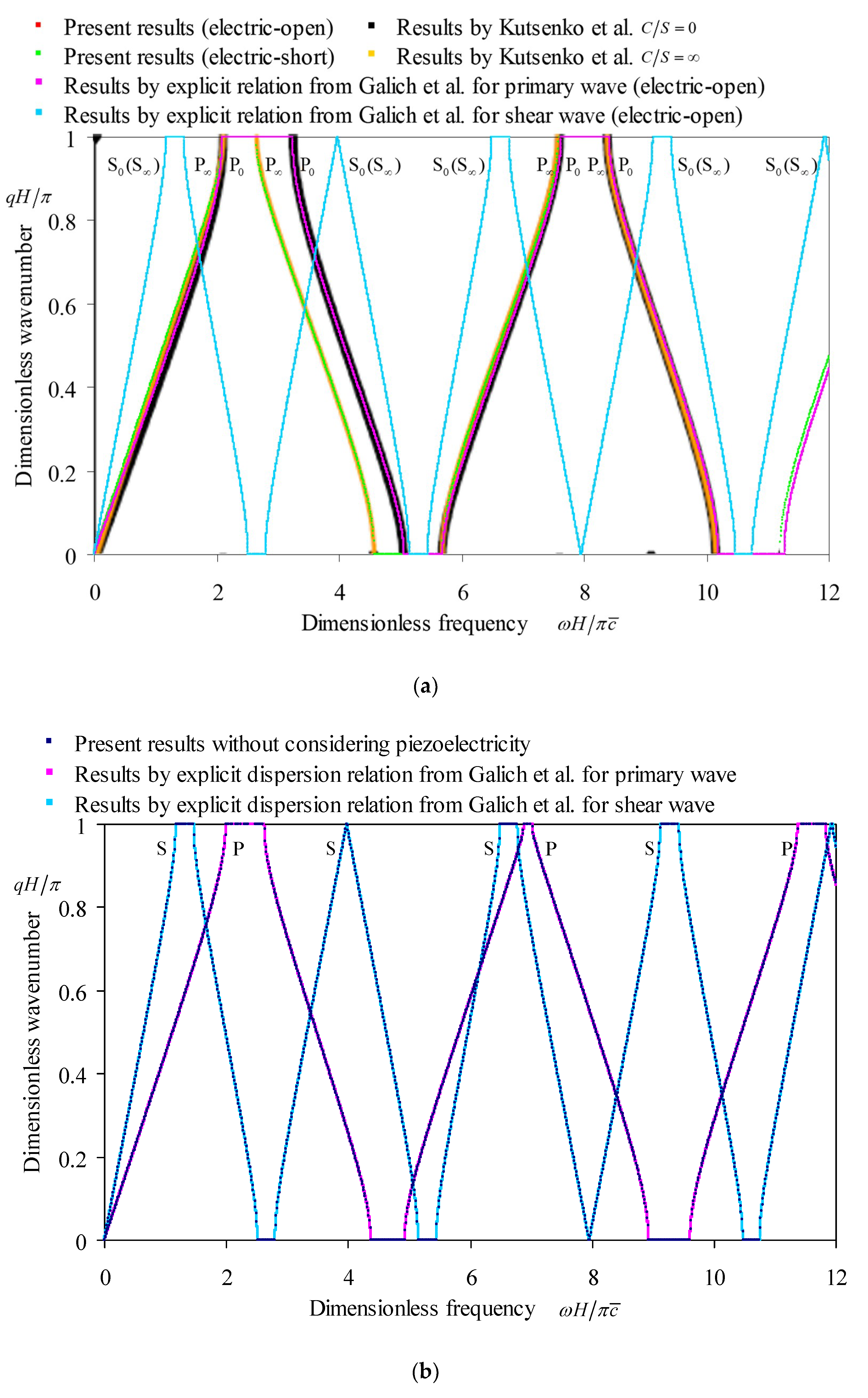
As the mechanical effect of the Brass electrodes is neglected by vanishing the electrode thickness, the frequency-wavenumber dispersion curves are first computed for the exemplified periodically laminated piezoelectric structure in cases of the electric-open and the electric-short boundary conditions by our proposed formulation. To validate our obtained results depicted in Figure 3, we compare these results corresponding to the electric-open and the electric-short conditions with the results by Kutsenko et al. [44] labeled as , and , respectively, because and are essentially identical to the electric-open and the electric-short conditions, respectively. Note that Kutsenko et al. [44] considered only the longitudinal (=primary) wave, while by the proposed formulation we can get the wavenumber spectra of both P- and S-waves. Furthermore, in the case of the electric-open boundary, the wavenumber spectra of both P- and S-waves are also computed by the explicit dispersion relation from Galich et al. [20]. The piezoelectric effect of PZT-5H1 on the wavenumber spectra of P-wave can be included by adopting the equivalent stiffness rather than the alone elastic stiffness in the explicit dispersion relation. All these comparisons are demonstrated in Figure 3a. Without considering the piezoelectricity in the case of the electric-open boundary, the wavenumber spectra of decoupled P- and S-waves are also calculated both by our formulation and by the explicit dispersion relation from Galich et al. [20], which are provided and compared in Figure 3b.
From Figure 3a, it is noticed that the present wavenumber spectra of P-wave by the proposed formulation here are well agreed with the counterpart spectra by Kutsenko et al. [44] in both the electric-open () and the electric-short () conditions. This proves that our proposed method works well for P-wave analysis in various electrical boundaries. In addition, the spectra of the other mode with a lower and narrower first bandgap provided by our method, which are not appeared in Ref. [44] by Kutsenko et al., are those dispersion curves of the two identical S-mode related to . For the electric-open boundary, the coincidence between the wavenumber spectra of both P-wave and S-wave by the proposed method and those counterparts by the explicit dispersion relation from Galich et al. [20] further verifies that our proposed method gives accurate dispersion characteristics for both P- and S-waves. In addition, the spectra of S-wave in cases of the electric-open and the electric-short boundaries obtained by the proposed method are overlapped each other and are also overlapped with those of S-wave in the case of the electric-open boundary by the explicit dispersion relation from Galich et al. [20]. These consistencies validate that the S-wave is independent on both the piezoelectricity and the electrical boundary. Figure 3b indicates that our proposed method are also reliable to compute the dispersion characteristics of both P- and S-waves as the piezoelectricity of the constituent piezoelectric layers is neglected, i.e., as the piezoelectric coefficients are specified as zero.
5.1.2. Influence of the Electrode Thickness on Dispersion of P-Wave Dependent on the Electric Field
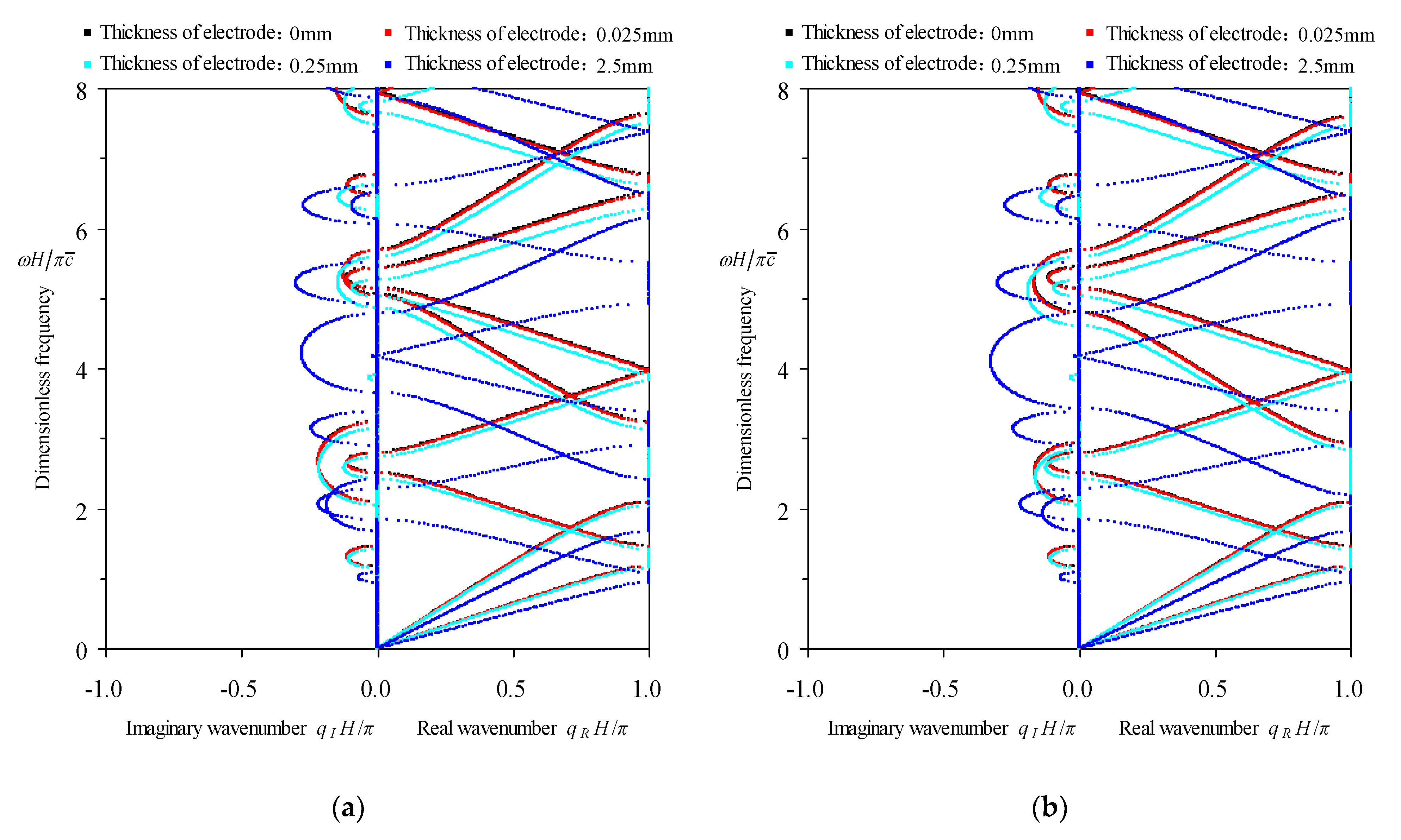
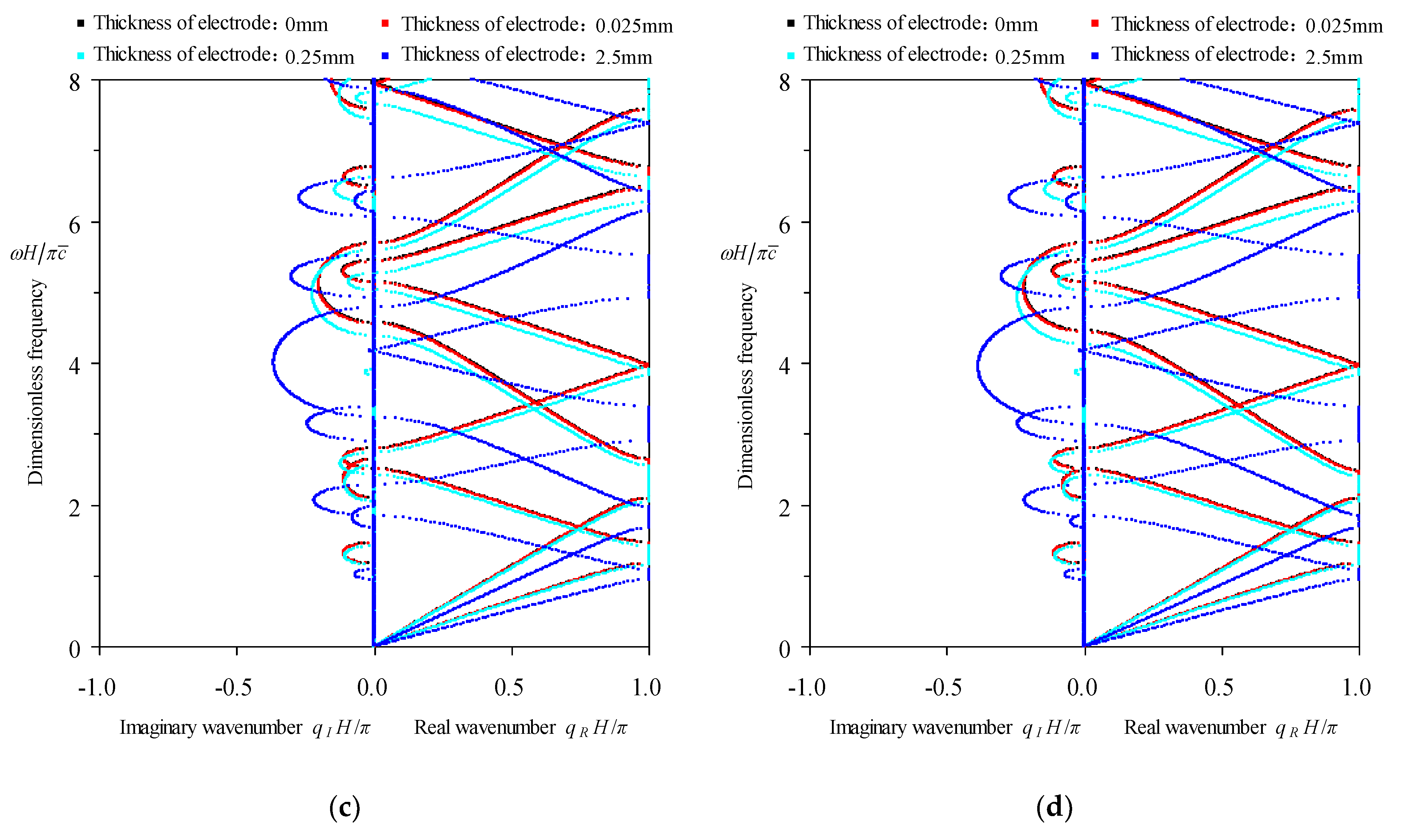
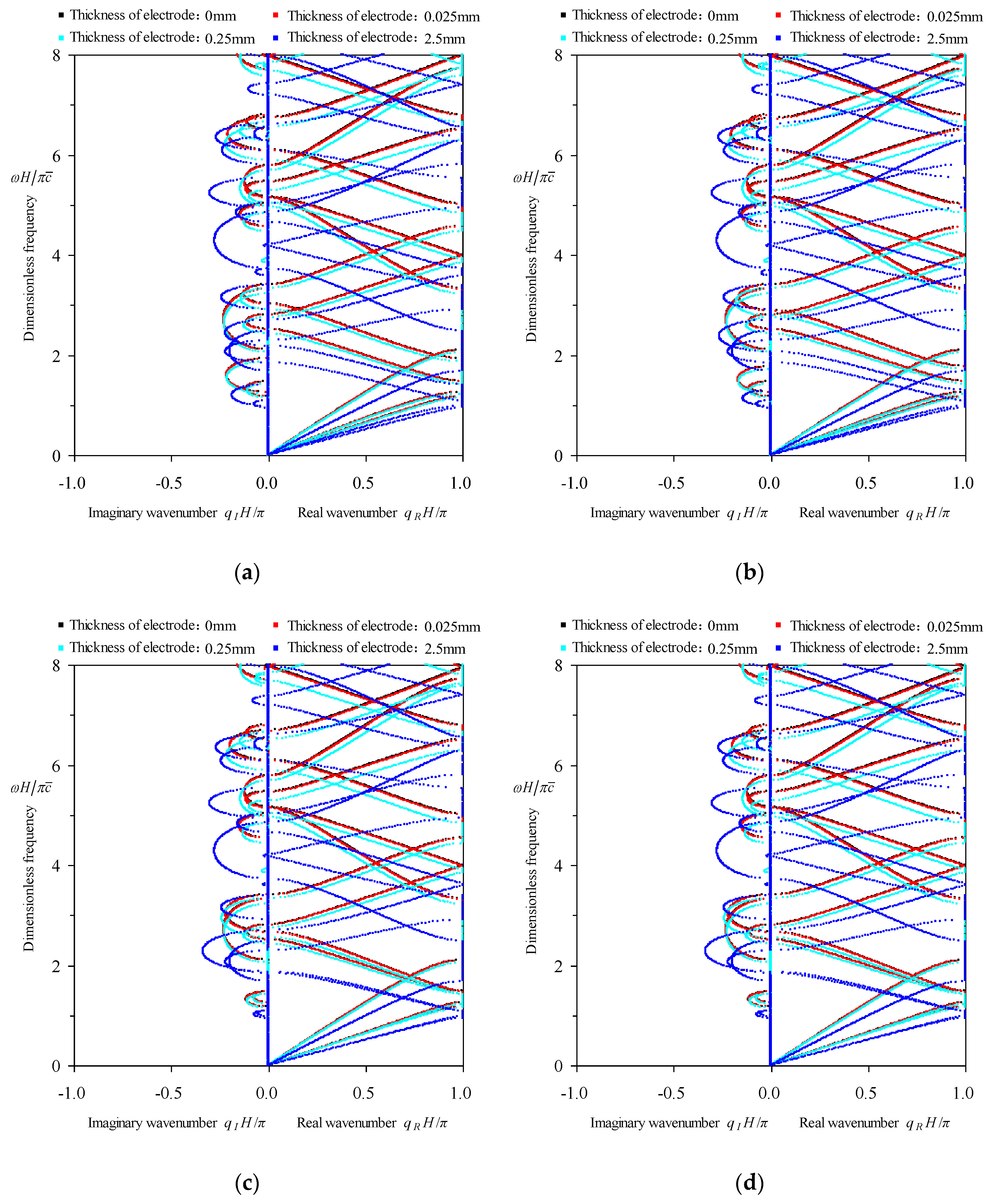
In the existing references [42,43,44,45] on the similar topic as this paper, the mechanical effects of the electrodes are all neglected by vanishing their thickness, as also adopted in the above section. However, the influence of this assumption on the resulting dispersion characteristics is not known as yet. Thus, here we study the effect of the electrode thickness on the wavenumber spectra in all the four cases of electrical boundaries. Three values of the Brass electrode thickness are taken separately, i.e., 0.025 mm, 0.25 mm, 2.5 mm, besides the null thickness 0 mm. Figure 4a–d show the comparisons of the wavenumber spectra corresponding to four values of the electrode thickness in cases of the electric-open, applied electric capacitance, electric-short and applied feedback voltage boundaries. Note that the capacitance per unit area in the applied electric capacitance condition and the gain coefficient in the applied feedback voltage condition are both specified casually.
From Figure 4, it is seen that the electrode thickness has the same influence rule on the dispersion of all waves, including the P-wave dependent on the electric field and the two S-waves, in cases of four electrical boundaries, which are summarized as follows:
- The higher mode spectra are more sensitive to the electrode thickness. As the electrode thickness is less than certain ratio to the thickness of associated piezoelectric layer, say , the first two wavenumber spectra of all waves are nearly unaffected by the electrode thickness. As the electrode thickness reaches to of the thickness of piezoelectric layer, the 3rd and higher order spectra begin to be influenced by the electrode thickness. As the thickness ratio between electrode and host piezoelectric layer reaches to , all modes of spectra are obviously influenced.
- When the electrode thickness shows effect on the wavenumber spectra, it has the same effect on all waves in that frequency range, since the alteration of the electrode thickness essentially equals to changing the unit-cell configuration. With the increasing of the electrode thickness, the wavenumber spectra deform to lower frequency side, so that the central frequencies of bandgaps are lowered. However, the widths of bandgaps are not consistently changed with the electrode thickness.
- As the electrode thickness is less than , the electrode thickness does not affect the dispersion characteristics of all waves.
In summary, as long as the electrode thickness is bigger than certain degree, say of the thickness of host piezoelectric layer, the mechanical effect of electrodes is not negligible. In calculations of the following two subsections, the electrode thickness is taken as real value , although may be negligible. This does not bring any more difficulties in our proposed method anyway.
5.1.3. Influence of Electrical Boundaries on P-Waves Dependent on the Electric Field
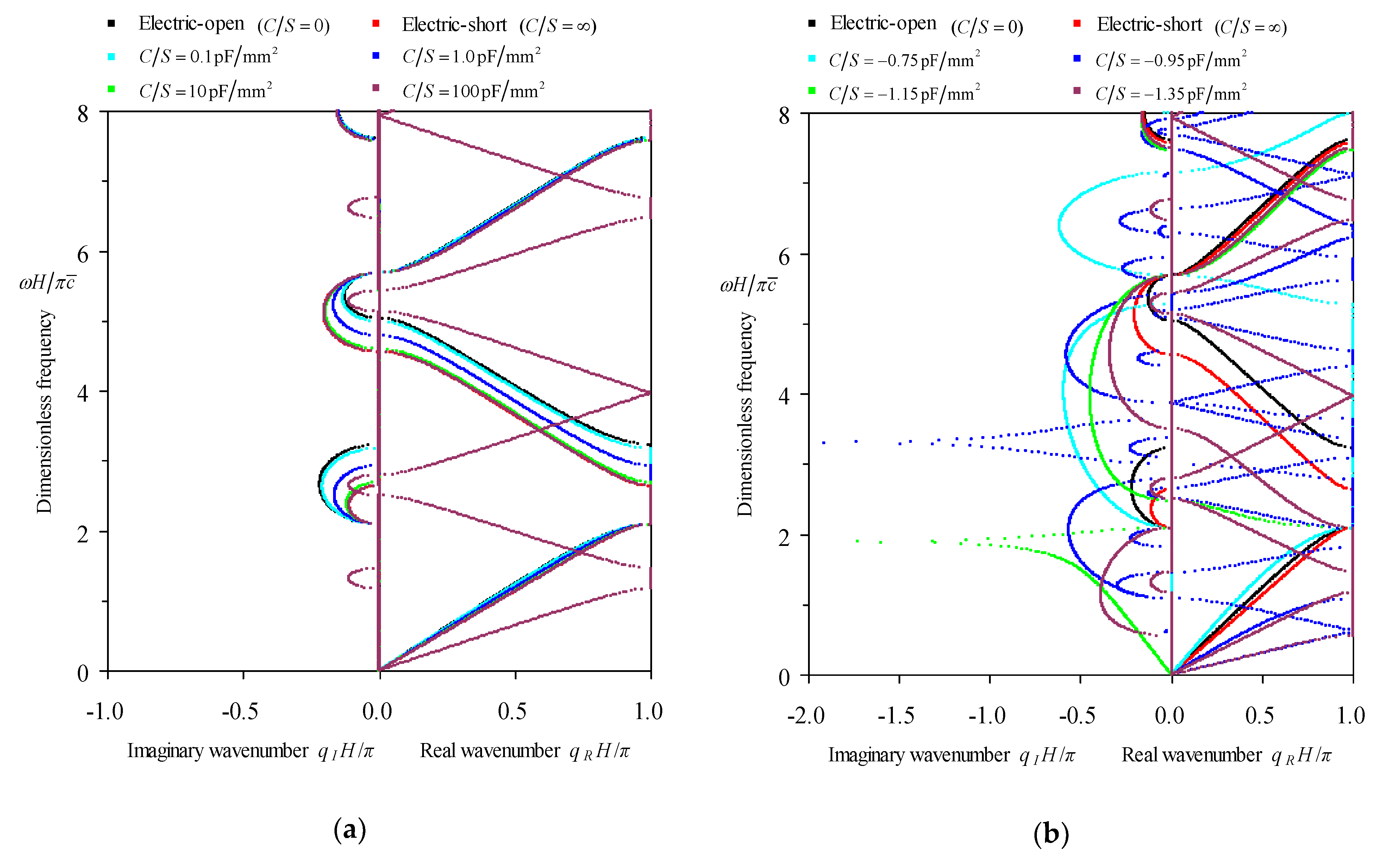
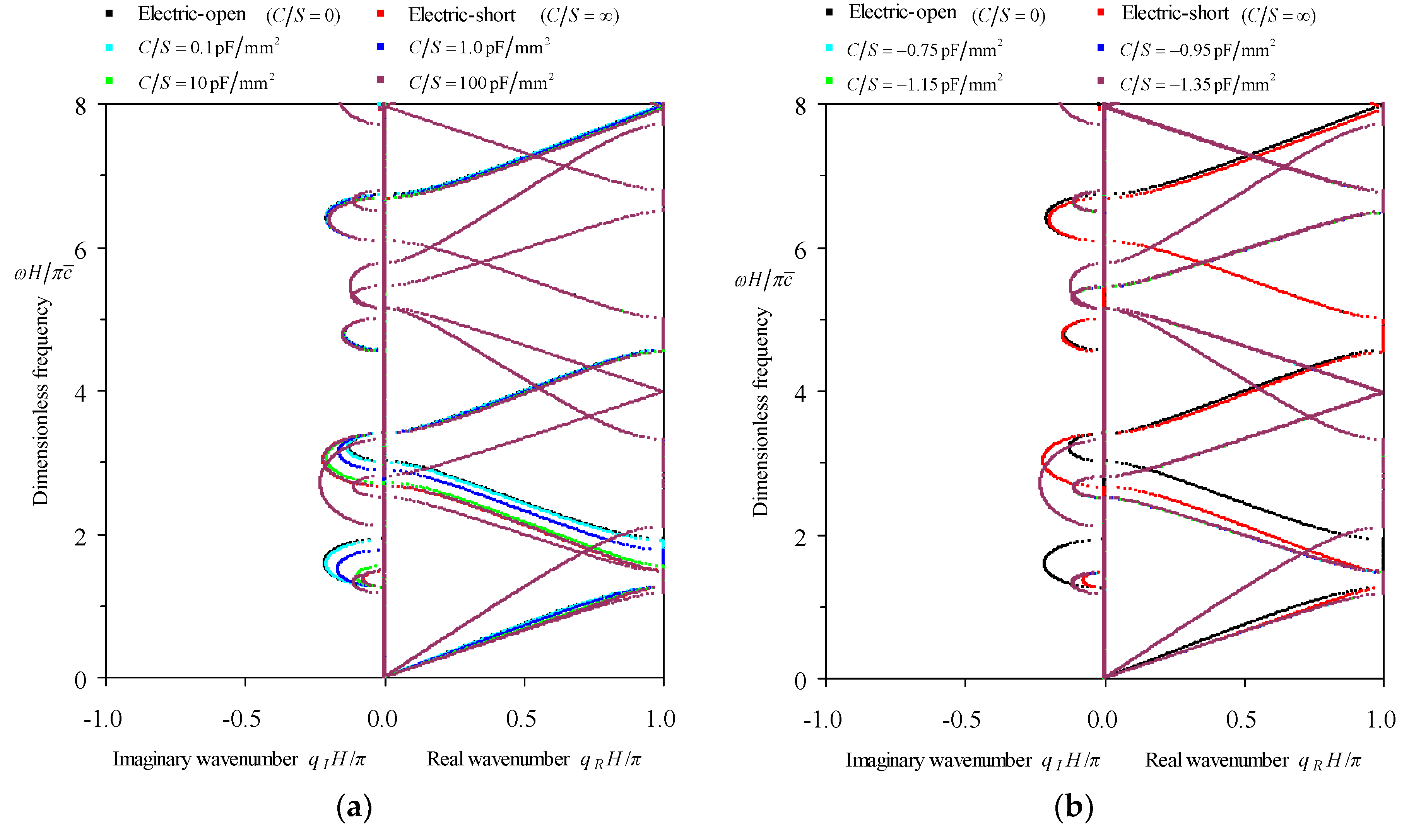
Consider influence of four electrical boundaries on the dispersion characteristics of P-wave dependent on the electric field. This task is achieved by studying effects of the applied capacitance condition in cases of , , , , , , , , and of the applied feedback control boundary with gain coefficient specified as , , , , , , , , on the wavenumber-frequency dispersion curves adopting our proposed method, since the electric-open and the electric-short conditions correspond to and , respectively. The calculated results of all waves are depicted in Figure 5, where the spectra corresponding to the electric-open and the electric-short conditions are used as the reference in all subfigures.
All subfigures in Figure 5 display that the resulting wavenumber spectra are associated with two waves. One is not affected by the electrical boundaries at all and the other is obviously influenced by the four electrical conditions. This actually verifies the discussion in Section 3.2 that the three waves are decoupled and only one wave is dependent on the electric field. Inferred from the spectrum slope which expressing the phase velocity and also the discussion in Section 3.2, it is known that the spectra irrelative to the electrical boundaries represent the dispersion of two S-waves with identical properties, which are polarized along and axes, respectively. The spectra apparently dependent on the electrical boundaries express the dispersion characteristics of P-wave. From Figure 5a,b, we can summarize the influence rule of the applied capacitance on the wavenumber spectra of the P-wave dependent on the electric field as follows:
- Some orders of phase constant spectra are sensitive to the applied capacitance, like the second spectra, but others are not, like the first and the third spectra.
- As the applied capacitance increases from to positive values, the wavenumber spectra change gradually from those of the electric-open condition to those of the electric-short condition as expected, i.e., these phase constant spectra deform to the lower frequency side. Thus, the central frequencies of most bandgaps and passbands decrease with the enlarging of the capacitance. However, the bandgap widths may be either narrower like the first stopband in Figure 5a or wider like the second stopband there.
- As the applied capacitance decreases from to negative values, the wavenumber spectra of the P-wave do not follow the opposite rule of positive capacitance and do show very complex alterations that seems can not be described by a uniform rule. Nevertheless, the phenomena that some attenuation constant spectra have pole at certain frequency in bandgap and the corresponding phase constant jumps from to , found by Kutsenko et al. [44] in studying the piezoelectric medium with periodically applied negative capacitance, are also discerned here as the capacitance is taken as and . Note that Kutsenko et al. [44] did provide the formula to determine the negative capacitance that leads to this unusual feature in wavenumber spectra for piezoelectric medium with periodically applied capacitance. But here we can not provide a similar formula for this purpose because of the complexity of our model, in which the inserted elastic layers and the mechanical effect of the electrodes have been further considered on the basis of the model in Kutsenko et al. [44].
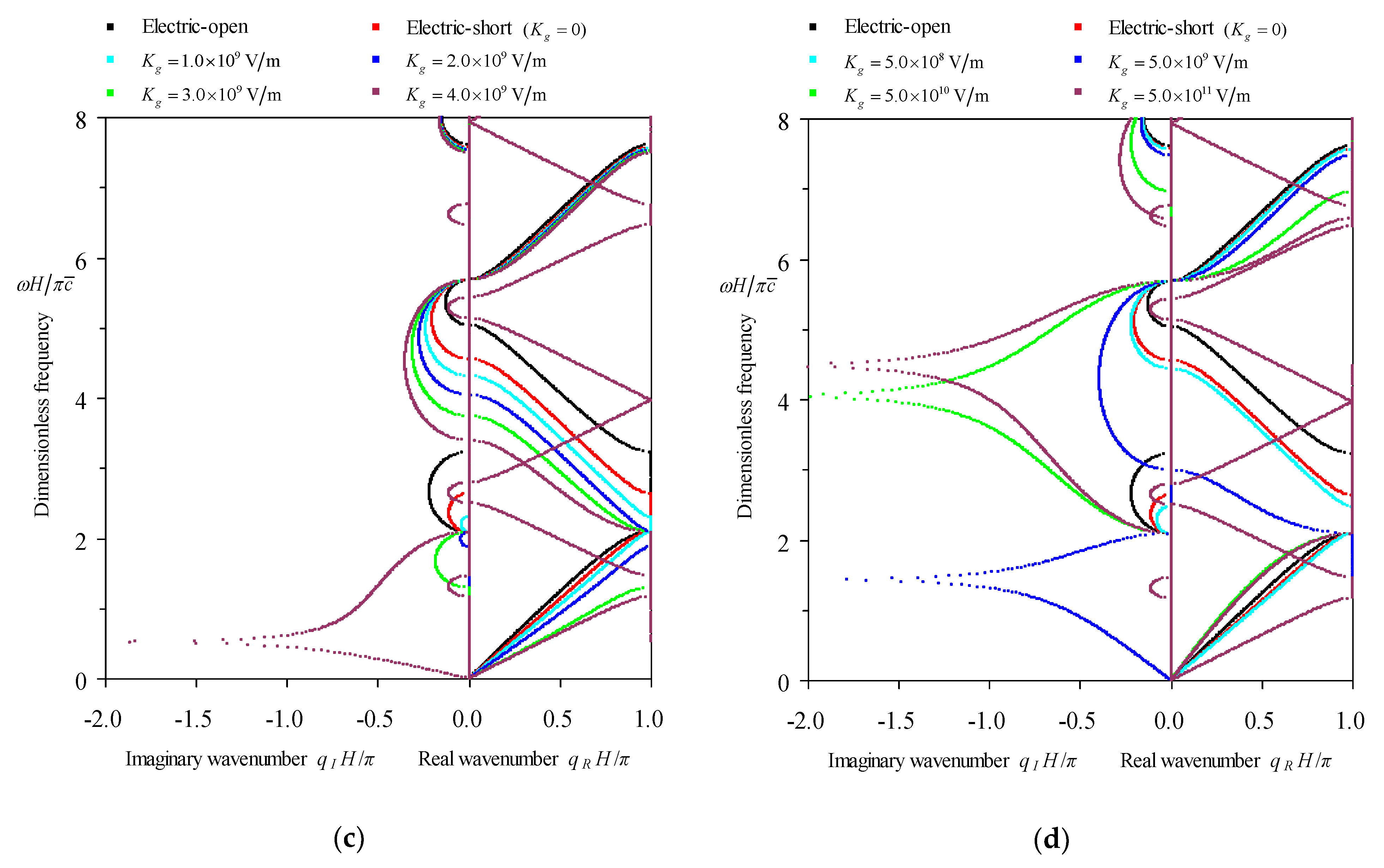
The influence rule of the applied feedback control on the wavenumber spectra of the P-wave dependent on the electric field can be summarized from Figure 5c,d as:
- Some orders of the phase constant spectra are sensitive to the applied feedback control, like the first and second spectra in Figure 5c, but others are not, like the third spectrum there. Nevertheless, Figure 5d shows that as long as the gain coefficient is big enough, even the third spectrum alters. The phase constant spectra that are insensitive to the applied feedback control may not be definitely coincident with the spectra insensitive to the applied capacitance, like the first spectrum. The spectra that are insensitive to both conditions may correspond to wave modes mainly dominated by the mechanical effect.
- As the gain coefficient increases from , the wavenumber spectra change from those of the electric-short condition, which can be expected since corresponds to the electric-short condition, to the lower frequency side. Thus, the central frequencies of most bandgaps and passbands decrease with the enlarging of . However, the bandgap widths may be either wider like the second stopband in Figure 5c or change without coherence like the first stopband there.
- As the gain coefficient reaches or bigger, the phenomena that some attenuation constant spectra have pole at certain frequency in bandgap and the corresponding phase constant jumps from to , can also be discerned. This means that we can use the applied feedback control boundary to realize the same effect resulting from the negative capacitance, like the unusual dispersion feature emphasized here. But neither can we provide a formula to determine for achieving this unusual dispersion phenomenon because of the complexity of our model.
If the electrical boundary influence on the wavenumber spectra is considered globally, it can be concluded from the comparisons of Figure 5a–d that the spectra of the electric-short condition play a benchmark role. The wavenumber spectra of the electric-short condition lie on the lower-frequency side of the spectra of the applied positive and zero (identical to the electric-open) capacitance condition, and are also located on the higher-frequency side of the spectra of the applied feedback control condition. Consequently, in the following subsection we take the electric-short condition as a representative to illustrate the general properties of the frequency-related dispersion curves of the P-wave dependent on the electric field in periodic piezoelectric composites.
5.1.4. Properties of Frequency-Related Dispersion Curves of P-Wave Dependent on the Electric Field
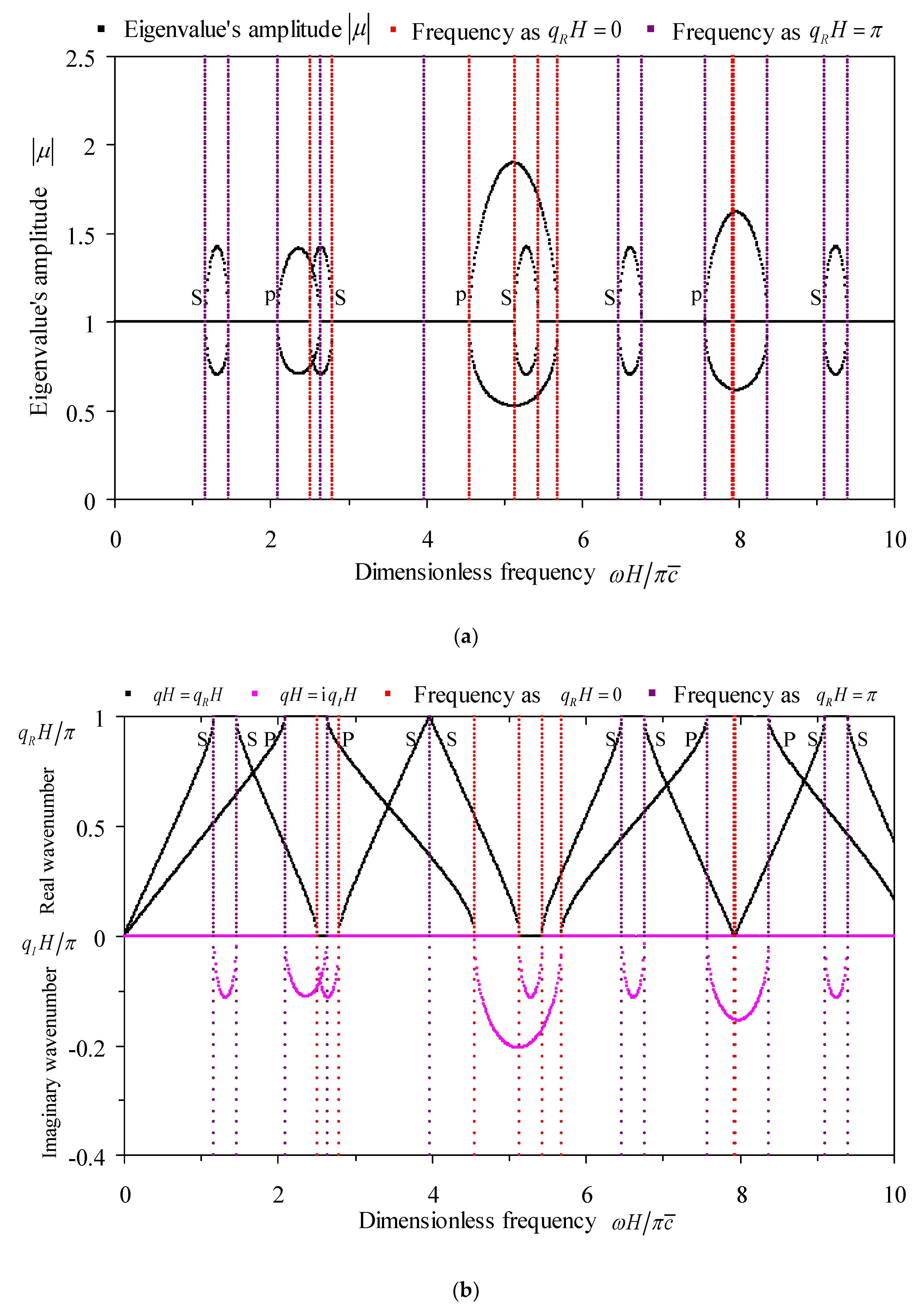
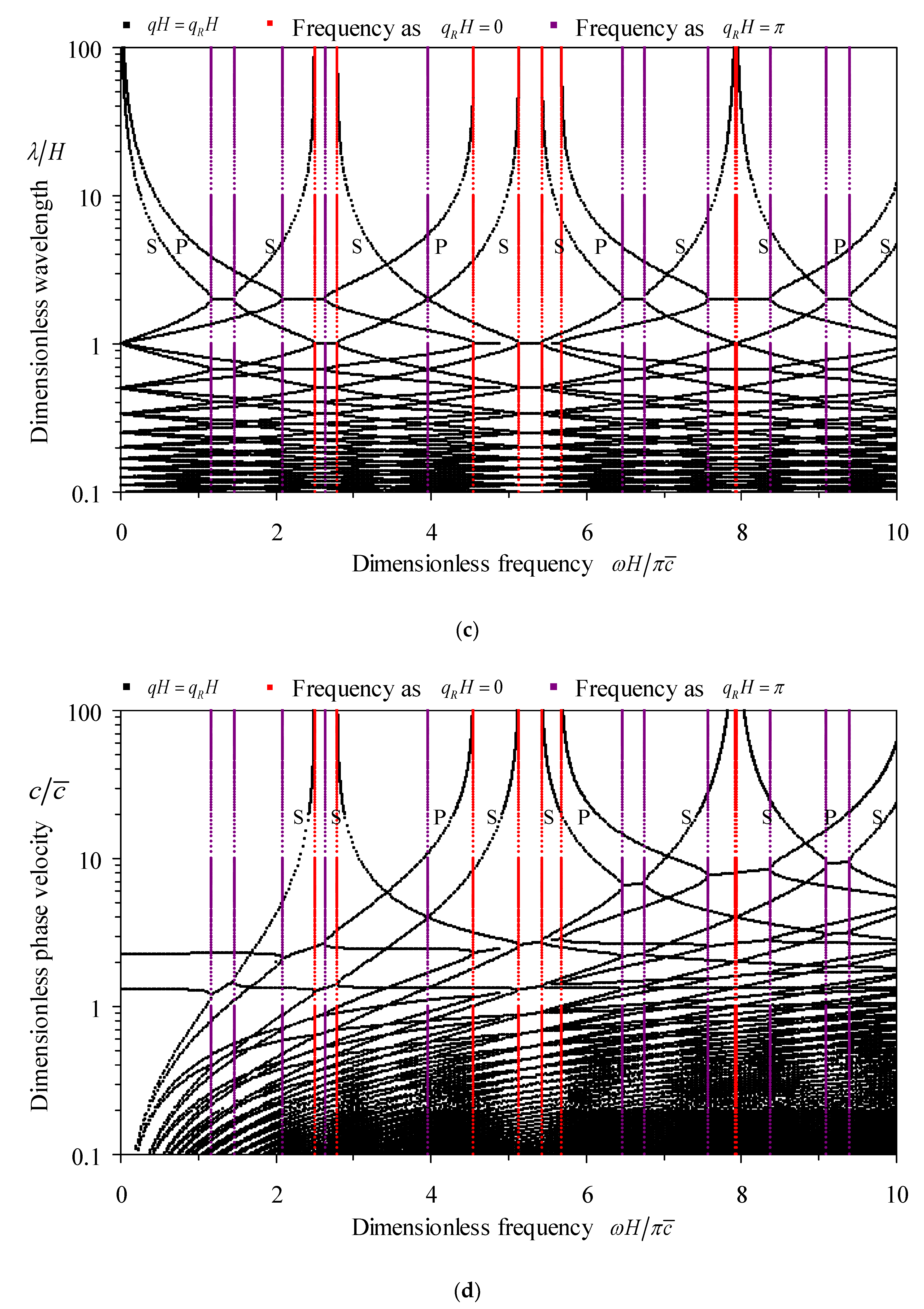
In the case of the electric-short boundary, comprehensive frequency-related dispersion curves of all waves in periodic Glass-Brass-(PZT-5H1)-Brass composites are computed and given in Figure 6, which contain the eigenvalue amplitude () spectra, the wavenumber () spectra, the wavelength () spectra, and the phase velocity () spectra shown in subfigures (a) to (d), respectively. Please notice that only the spectra of the P-wave are relative to the electrical boundary while those of two S-waves irrelative to the electrical boundary have exactly the same dispersion curves but different polarizations.
The above frequency-related dispersion curves in Figure 6 indicate the dispersion characteristics of two pure mode waves. Each wave has the same general dispersion features as the pure longitudinal wave has, which had been discussed in Ref. [57] for periodic elastic rods and in Ref. [58] for periodic piezoelectric rods with various electrical boundaries. For example: the bandgaps are bounded by frequencies corresponding to and phases; The passbands and stopbands appear alternately; The frequency-wavelength curves approach to infinite wavelength at bounding frequencies, so do the frequency-phase velocity curves except the two spectra starting from frequency. As a supplement, it is found that the eigenvalue amplitude appears in reciprocal pairs at any frequency in bandgap.
5.2. Tuning the Dispersion Characteristics of S-Wave Depend on the Electrical Boundary
In this section, PZT-5H2 is used in the exemplified periodically laminated piezoelectric structure as the piezoelectric layer. Since under this circumstance only one S-wave is affected by the electrical boundary, then we mainly focus on the S-wave propagation here in this section.
5.2.1. Validation of the Proposed Method for S-wave Dependent on the Electric Field
In order to validate our method in the case that one S-wave is dependent on the electric field and the other S-wave and the P-wave is not, we compute by our method the frequency-wavenumber dispersion curve of the exemplified periodic multilayers with the electric-open boundary as the electrode thickness is omitted. The results are depicted in Figure 7, which are further compared to the counterpart results obtained by the explicit dispersion relation from Galich et al. [20]. The effect of the piezoelectricity of PZT-5H2 on the wavenumber spectra of the S-wave dependent on the electric field has been considered as the equivalent stiffness is used in the explicit dispersion relation. Note that the degenerated results without considering the piezoelectricity of PZT-5H2 by the two methods have already been provided in Figure 3b.
Figure 7 shows that the computed wavenumber spectra of all the three waves by the proposed method are completely agreed with the counterpart spectra by the explicit dispersion relation from Galich et al. [20]. This agreement verifies that our proposed method works also well for the analysis of dispersion characteristics as one S-wave is dependent on the electric field. It can also be noticed from Figure 7 and its comparison with Figure 3b that the piezoelectricity of PZT-5H2 strengthens the manifesting stiffness on the basis of the elastic stiffness associated with one S-wave. This fact causes the increasing of the central frequency and the broadening of the width of the S-wave bandgap. The higher the frequency is, the more obvious the alteration is. The other S-wave and the P-wave are invariant with the piezoelectricity of PZT-5H2, and their independence on the electrical boundaries will be illustrated in the following two subsections.
5.2.2. Influence of the Electrode Thickness on Dispersion of S-Wave Dependent on the Electric Field
By taking the electrode thickness as , , , and , respectively, we study here the effect of the electrode thickness on the wavenumber spectra in all four electrical boundaries as PZT-5H2 are used in the unit cell. Figure 8 provides wavenumber spectra associated with all electrode thickness in cases of four electrical boundaries.
Figure 8 demonstrates the same influence rule of the electrode thickness as Figure 4 does. All waves, including the S-wave dependent on the electric field, the other S-wave irrelative to the electric field, and the P-wave, in cases of all four electrical boundaries, have the same connection with the electrode thickness, which have been stated in Section 5.1.2. Again, although the mechanical effect of electrodes need to be considered as long as the electrode thickness reaches nearly to of the host piezoelectric layer, in calculations of the following two subsections the electrode thickness is taken as real value for accuracy.
5.2.3. Influence of Electrical Boundaries on S-Wave Dependent on the Electric Field
In order to know how the band properties of the S-wave dependent on the electric field are tuned by the electrical boundaries, here we study by our proposed method the influence of four electrical boundaries on the wavenumber-frequency dispersion curves of all waves in the exemplified periodic Glass-Brass-(PZT-5H2)-Brass multilayers. Since the electric-open and the electric-short conditions correspond to and , respectively, we apply the capacitance condition in cases of , , , , , , , , or apply the feedback control boundary with the gain coefficient being , , , , on the electrodes to tune the wavenumber spectra. The calculated results are depicted in Figure 9, where the spectra corresponding to the electric-open and the electric-short conditions are again used as the reference in all subfigures.
Figure 9a–c indicate that the obtained wavenumber spectra correspond to three waves. The one with the smallest speed and the one with the biggest speed are both not affected by the electrical boundaries at all. The other with the middle speed is influenced by the four electrical conditions, but not very obviously. This actually verifies the discussion in Section 3.2 that the three waves are decoupled and only one wave is dependent on the electric field. The spectra dependent on the electrical boundaries represent the dispersion of the polarized S-wave, whose speed is slightly bigger than the polarized S-wave due to the piezoelectricity of PZT-5H2 and is distinctly smaller than the P-wave. The applied positive capacitance influences the S-wave relative to the electric field via the same rule as it affects the P-wave dependent on the electric field in Section 5.1.3, as can be illustrated by Figure 9a, although not very obviously since the spectra of the electric-open condition are very near to those of the electric-short condition. The rule has been stated in detail in Section 5.1.3, and it will not be repeated here. However, the applied negative capacitance and the applied feedback control nearly do not affect the wavenumber spectra of the S-wave relative to the electric field. The spectra corresponding to the various negative capacitance and gain coefficient all overlap on the spectra associated with the electric-short condition, which also denotes that the spectra of the electric-short condition play a benchmark role. The reason for this may be the weak coupling between the displacement and the electric field, since the shear strain rather than the normal strain is the modulation factor when is the involved piezoelectric coefficient. Considering the above fact, in the following subsection we take the electric-short condition as a representative to illustrate the general properties of the frequency-related dispersion curves of the S-wave dependent on the electric field in periodic piezoelectric composites.
5.2.4. Properties of Frequency-Related Dispersion Curves of S-Waves Dependent on the Electric Field
The comprehensive frequency-related dispersion curves of all waves in periodic Glass-Brass-(PZT-5H2)-Brass composites are computed and depicted in Figure 10 for the electric-short boundary as a representative, since those in the case of other electrical boundaries exhibit similar dispersion properties. The Figure 10a–d exhibit the eigenvalue amplitude () spectra, the wavenumber () spectra, the wavelength () spectra, the phase velocity () spectra, respectively. Note that only the spectra of the polarized S-wave are relative to the electrical boundary, while those of the polarized S-wave and P-wave are independent on the electrical boundary.
It can be seen from the frequency-related dispersion curves in Figure 10 that these spectra represent the dispersion characteristics of three pure mode waves, including one S-wave dependent on the electric field, and the other S-wave as well as the P-wave both irrelative to the electric field. For each wave, especially the S-wave dependent on the electric field that we are concerning, the frequency-related dispersion curves satisfy the general features of pure wave dispersion in periodic structures, as already had been discussed in Ref. [57] for periodic elastic rods and in Ref. [58] for periodic piezoelectric rods with various electrical boundaries. The eigenvalue amplitude spectra also appear in reciprocal pairs, which is a supplement feature.
6. Conclusions
By combining the state space formalism, the classical transfer matrix method, and the Floquet-Bloch principle, this paper proposes a general formulation for the analysis of dispersion characteristics of elastic waves propagating along the thickness direction in general, periodically laminated piezoelectric composites with unit cells consisting of orthotropic piezoelectric and elastic layers. Four electrical boundaries including the electric-open, applied electric capacitance, electric-short, and applied feedback control conditions are considered to apply or switch on the piezoelectric layers via electrode layers, to tune the dispersion characteristics of the wave dependent on the electric field. After the proposed method has been validated on the basis of numerical examples through comparisons with existing results or other methods like the explicit dispersion relation for simple configuration, it is used to study the influence of electrode thickness on frequency-wavenumber dispersion curves. The effect of four electrical boundaries on wavenumber spectra is also investigated using numerical examples, so that the feasibility of tuning the decoupled P- and S-waves by applying and switching electrical conditions is obtained. Numerical examples are also provided to summarize the general properties of the frequency-related dispersion curves of decoupled P- and S-waves. From these analyses, we can draw the following conclusions:
- (1)
- In the theoretical derivation of the analysis method, this paper is limited to elastic waves along the thickness direction and to general periodic piezoelectric composites of orthotropic materials. It is found that in this case, the three elastic waves are all decoupled into one primary (P-) wave and two shear (S-) waves with perpendicular polarizations, and only one wave among them is influenced by the electric field. The situation with elastic waves propagating obliquely to the thickness direction or of general, periodically laminated piezoelectric composites with unit cells consisting of arbitrarily anisotropic constituent layers is under investigation.
- (2)
- The mechanical effect of electrodes must be considered in the modeling, as the electrode thickness surpasses of the thickness of host piezoelectric layer. In this case, the electrode thickness can also be used to adjust passively the band structures of the periodic piezoelectric composites.
- (3)
- The applying and switching electrical boundaries among the electric-open, applied electric capacitance, electric-short, and applied feedback control conditions are very effective for actively modulating the dispersion of the P-wave that is dependent on the electric field. In particular, the unusual dispersion feature, which means that at some frequencies in the bandgaps, the attenuation constant spectrum has a pole and the corresponding phase constant jumps from to , which results from the applied negative capacitance condition in other literature, can also be realized by the applied feedback control boundary. However, the applying and switching of the four electrical boundaries may be inefficient or even invalid for modulating the dispersion of the S-wave that is dependent on the electric field if the electromechanical coupling effect of the piezoelectric materials is not utilized properly. The dispersion curves associated with the electric-short condition play a benchmark role for designing the active control scheme.
The findings of this paper may be applied to guide the design of elastic wave devices.
Author Contributions
Y.G. conceived the main ideas. Y.G. and Q.L. together derived the theoretical formulation and wrote the computer code. Q.L., J.W. and W.C. conducted the numerical examples. Y.G. and Q.L. contributed equally in writing the manuscript.
Acknowledgments
The authors wish to thank the anonymous reviewers for their constructive comments that greatly improve our manuscript. This work was supported by the National Natural Science Foundation of China (No. 11372119) and the Youth Technology Innovation Funds in Shanxi Agricultural University (No. 2018003).
Conflicts of Interest
The authors declare no conflict of interest. The founding sponsors had no role in the design of the study; in the collection, analyses, or interpretation of data; in the writing of the manuscript, and in the decision to publish the results.
Appendix A. The Matrices Composed of Stiffness and Dielectric Constants
For orthotropic materials of crystal classes , , and ,
in which “” indicates diagonal matrix here and after.
Appendix B. The Matrices Composed of Piezoelectric Constants
The matrices composed of piezoelectric constants involved in this paper are expressed differently for orthotropic crystal classes , , and . For crystal class with piezoelectricity as the plane perpendicular to , , and axes, these matrices are written respectively as
For crystal class with piezoelectricity as the axis parallel to , , and axes, the matrices composed of piezoelectric constants involved in this paper are written uniformly as
For crystal class that does not have piezoelectricity, these are all zero matrices.
Appendix C. The Components of Matrices and
The matrix is expressed differently for orthotropic crystal classes , , and . For crystal class with piezoelectricity as the plane perpendicular to , , and axes, it is written respectively as
For crystal class with piezoelectricity as the axis parallel to , , and axes and crystal class without piezoelectricity, is written uniformly as
The matrix is related to both the orthotropic crystal classes and the electrical boundaries. For crystal class with piezoelectricity as the plane perpendicular to , , and axes, is provided in Table A1 for the electric-open, applied electric capacitance, electric-short, and applied feedback voltage conditions, respectively. For crystal class with piezoelectricity, is zero matrix in cases of all four electrical boundaries, as also shown in Table A1, since is zero row vector.

Table A1.
The components of matrix for orthotropic layer of crystal classes , and with various electrical Boundaries.
Table A1.
The components of matrix for orthotropic layer of crystal classes , and with various electrical Boundaries.
| Electrical boundaries | ||||
|---|---|---|---|---|
| Electric-open | ||||
| Applied capacitance | ||||
| Electric-short | ||||
| Applied feedback control | ||||
References
- Rytov, S.M. Acoustical properties of a thinly laminated medium. Sov. Phys. Acoust. 1956, 2, 68–80. [Google Scholar]
- Shah, A.H.; Datta, S.K. Harmonic waves in a periodically laminated medium. Int. J. Solids Struct. 1982, 18, 397–410. [Google Scholar] [CrossRef]
- Nayfeh, A.H. The general problem of elastic wave propagation in multilayered anisotropic media. J. Acoust. Soc. Am. 1991, 89, 1521–1531. [Google Scholar] [CrossRef]
- Shull, P.J.; Chimenti, D.E.; Datta, S.K. Elastic guided waves and the Floquet concept in periodically layered plates. J. Acoust. Soc. Am. 1994, 95, 99–108. [Google Scholar] [CrossRef]
- Matysiak, S.J.; Nagorko, W. On the wave propagation in periodically laminated composites. Bull. Pol. Acad. Sci. Tech. Sci. 1995, 43, 1–12. [Google Scholar]
- Surana, K.S.; Maduri, R.K.; TenPas, P.W.; Reddy, J.N. Elastic wave propagation in laminated composites using the space-time least-squares formulation in h,p,k framework. Mech. Adv. Mater. Struct. 2006, 13, 161–196. [Google Scholar] [CrossRef]
- Hussein, M.I.; Leamy, M.J.; Ruzzene, M. Dynamics of phononic materials and structures: Historical origins, recent progress, and future outlook. ASME Appl. Mech. Rev. 2014, 66, 040802. [Google Scholar] [CrossRef]
- Brillouin, L. Wave Propagation in Periodic Structures: Electric Filters and Crystal Lattices, 2nd ed.; Dover Publications: Mineola, NY, USA, 1953. [Google Scholar]
- Kittel, C. Introduction to Solid State Physics, 8th ed.; John Wiley & Sons: New York, NY, USA, 2005. [Google Scholar]
- Tsu, R. Applying the insight into superlattices and quantum wells for nanostructures: Low-dimensional structures and devices. Microelectron. J. 2007, 38, 959–1012. [Google Scholar] [CrossRef]
- Sheng, P. Scattering and Localization of Classical Waves in Random Media; World Scientific: Singapore, 1990. [Google Scholar]
- Yablonovitch, E. Inhibited spontaneous emission in solid-state physics and electronics. Phys. Rev. Lett. 1987, 58, 2059–2062. [Google Scholar] [CrossRef] [PubMed]
- John, S. Strong localization of photons in certain disordered dielectric superlattices. Phys. Rev. Lett. 1987, 58, 2486–2489. [Google Scholar] [CrossRef] [PubMed]
- Camley, R.E.; Djafari-Rouhani, B.; Dobrzynski, L.; Maradudin, A.A. Transverse elastic waves in periodically layered infinite and semi-infinite media. Phys. Rev. B 1983, 27, 7318–7329. [Google Scholar] [CrossRef]
- Auld, B.A.; Chimenti, D.E.; Shull, P.J. Shear horizontal wave propagation in periodically layered composites. IEEE Trans. Ultrason. Ferroelectr. Freq. Control 1996, 43, 319–325. [Google Scholar] [CrossRef]
- Shen, M.R.; Cao, W.W. Acoustic bandgap formation in a periodic structure with multilayer unit cells. J. Phys. D Appl. Phys. 2000, 33, 1150–1154. [Google Scholar] [CrossRef]
- Sigmund, O.; Jensen, J.S. Systematic design of phononic band-gap materials and structures by topology optimization. Phil. Trans. R. Soc. Lond. A 2003, 361, 1001–1019. [Google Scholar] [CrossRef] [PubMed]
- Hussein, M.I.; Hamza, K.; Hulbert, G.M.; Scott, R.A.; Saitou, K. Multiobjective evolutionary optimization of periodic layered materials for desired wave dispersion characteristics. Struct. Multidisc. Optim. 2006, 31, 60–75. [Google Scholar] [CrossRef]
- EI-Beltagy, M.A.; Hussein, M.I. Design space exploration of multiphase layered phononic materials via natural evolution. In Proceedings of the ASME 2006 International Mechanical Engineering Congress and Exposition, Chicago, IL, USA, 5–10 November 2006; American Society of Mechanical Engineers: New York, NY, USA, 2006; pp. 155–163. [Google Scholar]
- Galich, P.I.; Fang, N.X.; Boyce, M.C.; Rudykh, S. Elastic wave propagation in finitely deformed layered materials. J. Mech. Phys. Solids 2017, 98, 390–410. [Google Scholar] [CrossRef]
- Zhang, P.; Parnell, W.J. Soft phononic crystals with deformation-independent band gaps. Proc. R. Soc. A 2017, 473. [Google Scholar] [CrossRef] [PubMed]
- Slesarenko, V.; Galich, P.I.; Li, J.; Fang, N.X.; Rudykh, S. Foreshadowing elastic instabilities by negative group velocity in soft composites. Appl. Phys. Lett. 2018, 113, 031901. [Google Scholar] [CrossRef]
- Li, J.; Slesarenko, V.; Rudykh, S. Microscopic instabilities and elastic wave propagation in finitely deformed laminates with compressible hyperelastic phases. Eur. J. Mech. A Solids 2019, 73, 126–136. [Google Scholar] [CrossRef]
- Cheng, Y.; Liu, X.J.; Wu, D.J. Temperature effects on the band gaps of Lamb waves in a one-dimensional phononic-crystal plate (L). J. Acoust. Soc. Am. 2011, 129, 1157–1160. [Google Scholar] [CrossRef] [PubMed]
- Li, Y.; Zhou, X.; Bian, Z.; Xing, Y.; Song, J. Thermal tuning of the interfacial adhesive layer on the band gaps in a one-dimensional phononic crystal. Compos. Struct. 2017, 172, 311–318. [Google Scholar] [CrossRef]
- Galich, P.I.; Rudykh, S. Shear wave propagation and band gaps in finitely deformed dielectric elastomer laminates: Long wave estimates and exact solution. J. Appl. Mech. 2017, 84, 091002. [Google Scholar] [CrossRef]
- Wu, L.-Y.; Wu, M.-L.; Chen, L.-W. The narrow pass band filter of tunable 1D phononic crystals with a dielectric elastomer layer. Smart Mater. Struct. 2009, 18, 015011. [Google Scholar] [CrossRef]
- Bortot, E.; Amir, O.; Shmuel, G. Topology optimization of dielectric elastomers for wide tunable band gaps. Int. J. Solids Struct. 2018, 143, 262–273. [Google Scholar] [CrossRef]
- Minagawa, S. Propagation of harmonic waves in a layered elasto-piezoelectric composite. Mech. Mater. 1995, 19, 165–170. [Google Scholar] [CrossRef]
- Qian, Z.H.; Jin, F.; Wang, Z.K.; Kishimoto, K. Dispersion relations for SH-wave propagation in periodic piezoelectric composite layered structures. Int. J. Eng. Sci. 2004, 42, 673–689. [Google Scholar] [CrossRef]
- Li, F.M.; Xu, M.Q.; Wang, Y.S. Frequency-dependent localization length of SH-wave in randomly disordered piezoelectric phononic crystal. Solid State Commun. 2007, 141, 296–301. [Google Scholar] [CrossRef]
- Zhao, J.; Pan, Y.; Zhong, Z. Theoretical study of shear horizontal wave propagation in periodically layered piezoelectric composite. J. Appl. Phys. 2012, 111, 064906. [Google Scholar] [CrossRef]
- Zhao, J.; Pan, Y.; Zhong, Z. A study of pressure-shear vertical wave propagation in periodically layered fluid and piezoelectric structure. J. Appl. Phys. 2013, 113, 054903. [Google Scholar] [CrossRef]
- Li, F.M.; Wang, Y.S. Study on wave localization in disordered periodic layered piezoelectric composite structures. Int. J. Solids Struct. 2005, 42, 6457–6474. [Google Scholar] [CrossRef]
- Li, F.M.; Wang, Y.S. Study on localization of plane elastic waves in disordered periodic 2-2 piezoelectric composite structures. Int. J. Solids Struct. 2006, 296, 554–566. [Google Scholar] [CrossRef]
- Li, F.M.; Wang, Y.Z.; Fang, B.; Wang, Y.S. Propagation and localization of two-dimensional in-plane elastic waves in randomly disordered layered piezoelectric phononic crystal. Int. J. Solids Struct. 2007, 44, 7444–7456. [Google Scholar] [CrossRef]
- Wang, Y.Z.; Li, F.M.; Huang, W.H.; Wang, Y.S. Propagation and localization of Rayleigh waves in randomly disordered piezoelectric phononic crystal. J. Mech. Phys. Solids 2008, 56, 1578–1590. [Google Scholar] [CrossRef]
- Lan, M.; Wei, P.J. Laminated piezoelectric phononic crystal with imperfect interfaces. J. Appl. Phys. 2012, 111, 013505. [Google Scholar] [CrossRef]
- Zou, X.Y.; Chen, Q.; Chen, J.C. The band gaps of plate-mode waves in one-dimensional piezoelectric composite plates: Polarizations and boundary conditions. IEEE Trans. Ultrason. Ferroelectr. Freq. Control 2007, 54, 1430–1436. [Google Scholar] [PubMed]
- Mansoura, S.A.; Marechal, P.; Morvan, B.; Hlandky-Hennion, A.C.; Dubus, B. Active control of piezoelectric phononic crystal using electrical impedance. In Proceedings of the 2014 IEEE International Ultrasonics Symposium Proceedings, Chicago, IL, USA, 3–6 September 2014; IEEE: Piscataway, NJ, USA, 2014; pp. 951–954. [Google Scholar]
- Mansoura, S.A.; Marechal, P.; Morvan, B.; Dubus, B. Analysis of a phononic crystal constituted of piezoelectric layers using electrical impedance measurement. Phys. Procedia 2015, 70, 283–286. [Google Scholar] [CrossRef]
- Mansoura, S.A.; Morvan, B.; Marechal, P.; Benard, P.; Hlandky-Hennion, A.C.; Dubus, B. Tunability of the band structure of a piezoelectric phononic crystal using electrical negative capacitance. In Proceedings of the 2015 IEEE International Ultrasonics Symposium (IUS), Taipei, Taiwan, 21–24 October 2015; IEEE: Piscataway, NJ, USA, 2015; pp. 951–954. [Google Scholar]
- Kutsenko, A.A.; Shuvalov, A.L.; Poncelet, O.; Darinskii, A.N. Tunable effective constants of the one-dimensional piezoelectric phononic crystal with internal connected electrodes. J. Acoust. Soc. Am. 2015, 137, 606–616. [Google Scholar] [CrossRef] [PubMed]
- Kutsenko, A.A.; Shuvalov, A.L.; Poncelet, O.; Darinskii, A.N. Quasistatic stopband and other unusual features of the spectrum of a one-dimensional piezoelectric phononic crystal controlled by negative capacitance. C. R. Mec. 2015, 343, 680–688. [Google Scholar] [CrossRef]
- Kutsenko, A.A.; Shuvalov, A.L.; Poncelet, O. Dispersion spectrum of acoustoelectric waves in 1D piezoelectric crystal coupled with 2D infinite network of capacitors. J. Appl. Phys. 2018, 123, 044902. [Google Scholar] [CrossRef] [Green Version]
- Ponge, M.F.; Dubus, B.; Granger, C.; Vasseur, J.; Thi, M.P.; Hlandky-Hennion, A.C. Optimization of a tunability piezoelectric resonator using phononic crystal with periodic electric boundary conditions. Phys. Procedia 2015, 70, 258–261. [Google Scholar] [CrossRef]
- Wang, Y.L.; Song, W.; Sun, E.W.; Zhang, R.; Cao, W.W. Tunable passband in one-dimensional phononic crystal containing a piezoelectric 0.62Pb(Mg1/3Nb2/3)O3-0.38PbTiO3 single crystal defect layer. Physica E 2014, 60, 37–41. [Google Scholar] [CrossRef]
- Zhu, X.H.; Qiao, J.; Zhang, G.Y.; Zhou, Q.; Wu, Y.D.; Li, L.Q. Tunable acoustic metamaterial based on piezoelectric ceramic transducer. In Active and Passive Smart Structures and Integrated Systems 2017, Proceedings of SPIE Smart Structures and Materials + Nondestructive Evaluation and Health Monitoring, Portland, OR, USA, 25–29 March, 2017; Park, G., Erturk, A., Han, J.H., Eds.; SPIE: Bellingham, WA, USA, 2017; p. 1016411. [Google Scholar]
- Tarn, J.Q. A state space formalism for piezothermoelasticity. Int. J. Solids Struct. 2002, 39, 5173–5184. [Google Scholar] [CrossRef]
- Pestel, E.C.; Leckie, F.A. Matrix Methods in Elasto Mechanics; McGraw-Hill: New York, NY, USA, 1963. [Google Scholar]
- Mead, D.J. Wave propagation in continuous periodic structures: Research contributions from Southampton, 1964–1995. J. Sound Vib. 1996, 190, 495–524. [Google Scholar] [CrossRef]
- ANSI/IEEE Std. 176-1987. IEEE Standard on Piezoelectricity; IEEE: New York, NY, USA, 1988; pp. 3–30. [Google Scholar]
- Tiersten, H.F. Linear Piezoelectric Plate Vibrations; Plenum Press: New York, NY, USA, 1969. [Google Scholar]
- Li, J.; Slesarenko, V.; Galich, P.I.; Rudykh, S. Oblique shear wave propagation in finitely deformed layered composites. Mech. Res. Commun. 2018, 87, 21–28. [Google Scholar] [CrossRef]
- Degraeve, S.; Granger, C.; Dubus, B.; Vasseur, J.O.; Thi, M.P.; Hladky-Hennion, A.-C. Bragg band gaps tunability in an homogeneous piezoelectric rod with periodic electrical boundary conditions. J. Appl. Phys. 2014, 115, 194508. [Google Scholar] [CrossRef]
- Auld, B.A. Acoustic Fields and Waves in Solids; John Wiley & Sons: New York, NY, USA, 1973; Volume I, pp. 357–382. [Google Scholar]
- Guo, Y.Q.; Fang, D.N. Analysis and interpretation of longitudinal waves in periodic multiphase rods using the method of reverberation-ray matrix combined with the Floquet-Bloch theorem. ASME J. Vib. Acoust. 2014, 136, 011006. [Google Scholar] [CrossRef]
- Li, L.F.; Guo, Y.Q. Analysis of longitudinal waves in rod-type piezoelectric phononic crystals. Crystals 2016, 6, 45. [Google Scholar] [CrossRef]
Figure 1.
The schematic of the unit cell and its description in the global coordinate system of general, periodically laminated piezoelectric composites.
Figure 1.
The schematic of the unit cell and its description in the global coordinate system of general, periodically laminated piezoelectric composites.

Figure 2.
The local coordinates and the basic physical quantities of any constituent layer.

Figure 3.
Comparisons of the wavenumber spectra of the exemplified periodic multilayers computed by the proposed method, by Kutsenko et al. [44], and by the explicit dispersion relation from Galich et al. [20], (a) in cases of the electric-open and the electric-short boundaries with reckoning on piezoelectricity; (b) in the case of the electric-open condition without considering piezoelectricity.

Figure 4.
The effect of Brass electrode thickness on the wavenumber spectra of periodic Glass-Brass-(PZT-5H1)-Brass multilayers in cases of four electrical boundaries: (a) Electric-open condition; (b) Applied condition; (c) Electric-short condition; (d) Applied condition.
Figure 4.
The effect of Brass electrode thickness on the wavenumber spectra of periodic Glass-Brass-(PZT-5H1)-Brass multilayers in cases of four electrical boundaries: (a) Electric-open condition; (b) Applied condition; (c) Electric-short condition; (d) Applied condition.


Figure 5.
The effects of the electrical boundaries on the wavenumber spectra of elastic waves in periodic Glass-Brass-(PZT-5H1)-Brass multilayers: (a) Applied positive capacitance; (b) Applied negative capacitance; (c,d) Applied feedback control.
Figure 5.
The effects of the electrical boundaries on the wavenumber spectra of elastic waves in periodic Glass-Brass-(PZT-5H1)-Brass multilayers: (a) Applied positive capacitance; (b) Applied negative capacitance; (c,d) Applied feedback control.


Figure 6.
The comprehensive frequency-related dispersion curves of elastic waves in periodic Glass-Brass-(PZT-5H1)-Brass multilayers: (a) The eigenvalue amplitude spectra; (b) The wavenumber spectra; (c) The wavelength spectra; (d) The phase velocity spectra.
Figure 6.
The comprehensive frequency-related dispersion curves of elastic waves in periodic Glass-Brass-(PZT-5H1)-Brass multilayers: (a) The eigenvalue amplitude spectra; (b) The wavenumber spectra; (c) The wavelength spectra; (d) The phase velocity spectra.


Figure 7.
Comparisons of the wavenumber spectra of the exemplified periodic Glass-(PZT-5H2) multilayers in the case of the electric-open boundary computed by the proposed method and by the explicit dispersion relation from Galich et al. [20], as the piezoelectricity of PZT-5H2 are considered.
Figure 7.
Comparisons of the wavenumber spectra of the exemplified periodic Glass-(PZT-5H2) multilayers in the case of the electric-open boundary computed by the proposed method and by the explicit dispersion relation from Galich et al. [20], as the piezoelectricity of PZT-5H2 are considered.
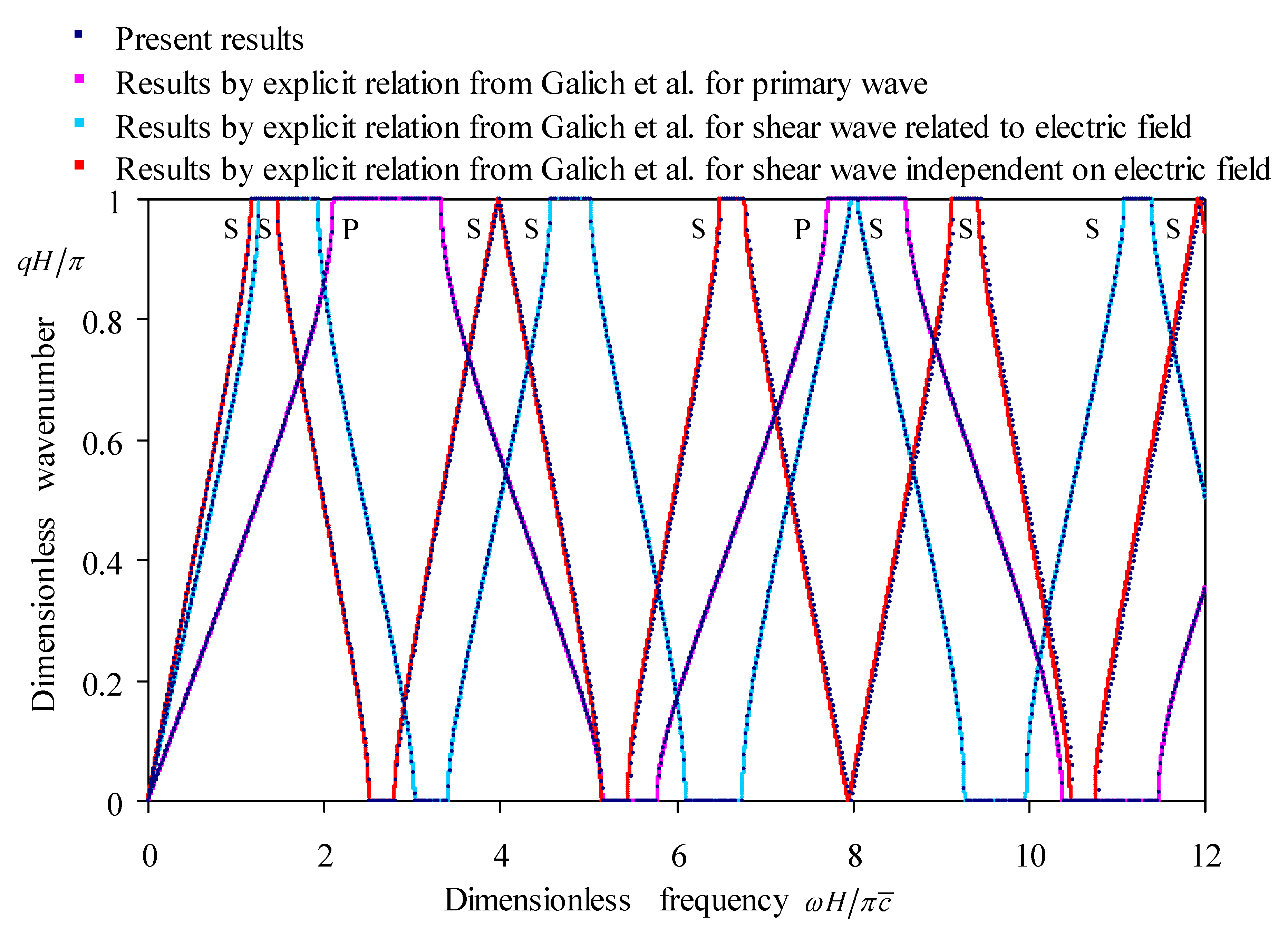
Figure 8.
The effect of Brass electrode thickness on the wavenumber spectra of periodic Glass-Brass-(PZT-5H2)-Brass multilayers in cases of four electrical boundaries: (a) Electric-open condition; (b) Applied condition; (c) Electric-short condition; (d) Applied condition.
Figure 8.
The effect of Brass electrode thickness on the wavenumber spectra of periodic Glass-Brass-(PZT-5H2)-Brass multilayers in cases of four electrical boundaries: (a) Electric-open condition; (b) Applied condition; (c) Electric-short condition; (d) Applied condition.

Figure 9.
The effects of the electrical boundaries on the wavenumber spectra of elastic waves in periodic Glass-Brass-(PZT-5H2)-Brass multilayers: (a) Applied positive capacitance; (b) Applied negative capacitance; (c) Applied feedback control.
Figure 9.
The effects of the electrical boundaries on the wavenumber spectra of elastic waves in periodic Glass-Brass-(PZT-5H2)-Brass multilayers: (a) Applied positive capacitance; (b) Applied negative capacitance; (c) Applied feedback control.

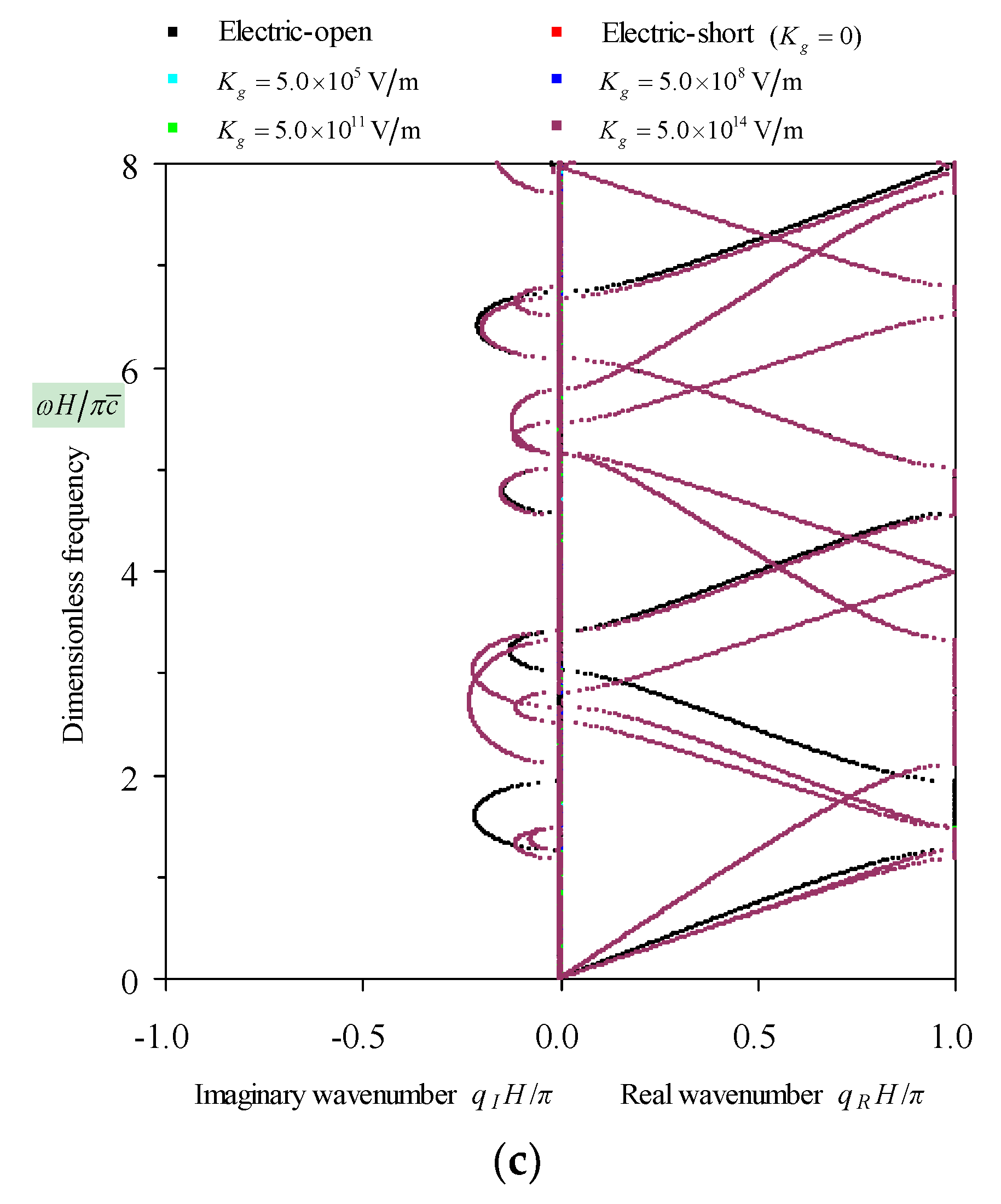
Figure 10.
The comprehensive frequency-related dispersion curves of the elastic waves in periodic Glass-Brass-(PZT-5H2)-Brass multilayers: (a) The eigenvalue amplitude spectra; (b) The wavenumber spectra; (c) The wavelength spectra; (d) The phase velocity spectra.
Figure 10.
The comprehensive frequency-related dispersion curves of the elastic waves in periodic Glass-Brass-(PZT-5H2)-Brass multilayers: (a) The eigenvalue amplitude spectra; (b) The wavenumber spectra; (c) The wavelength spectra; (d) The phase velocity spectra.
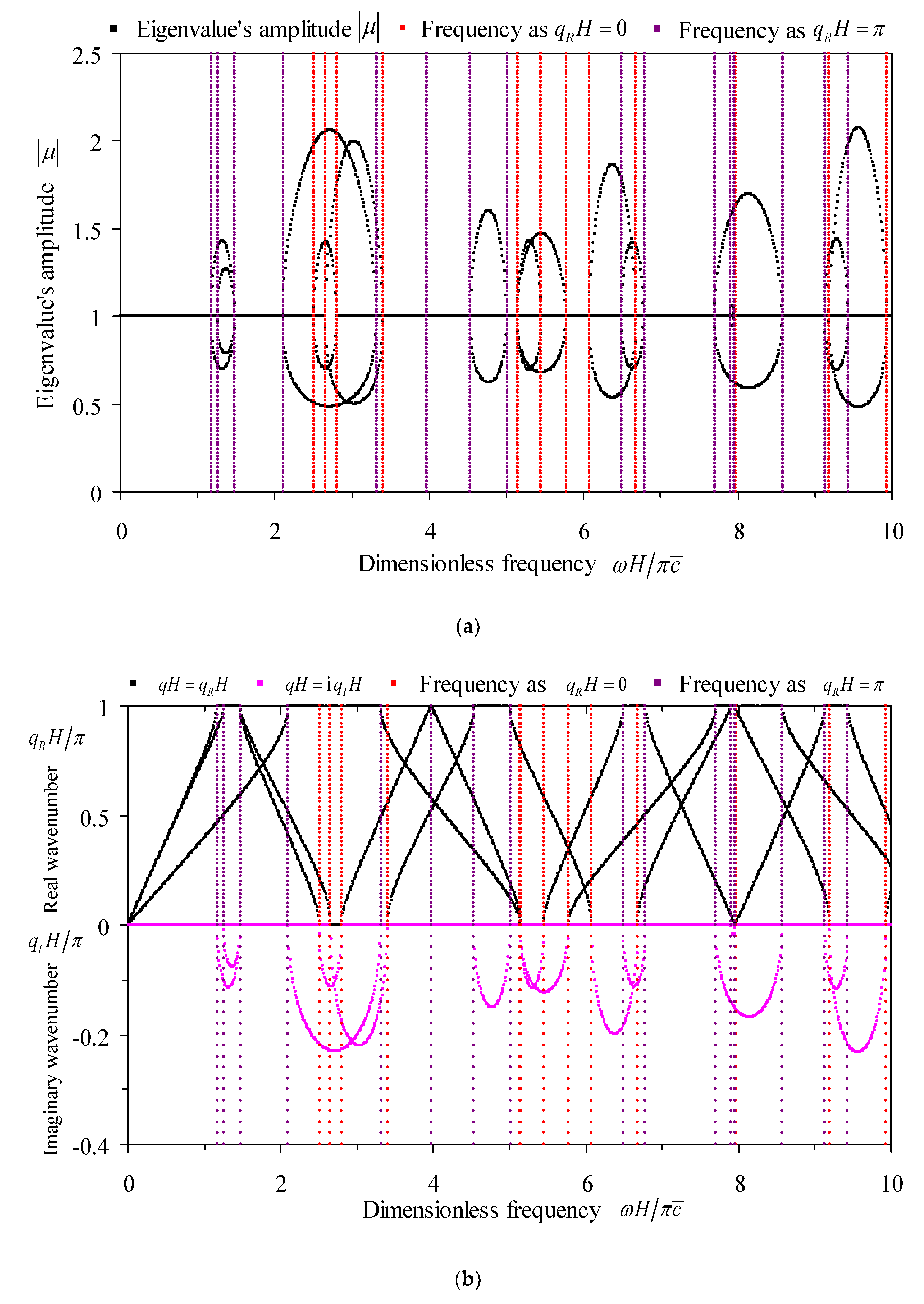
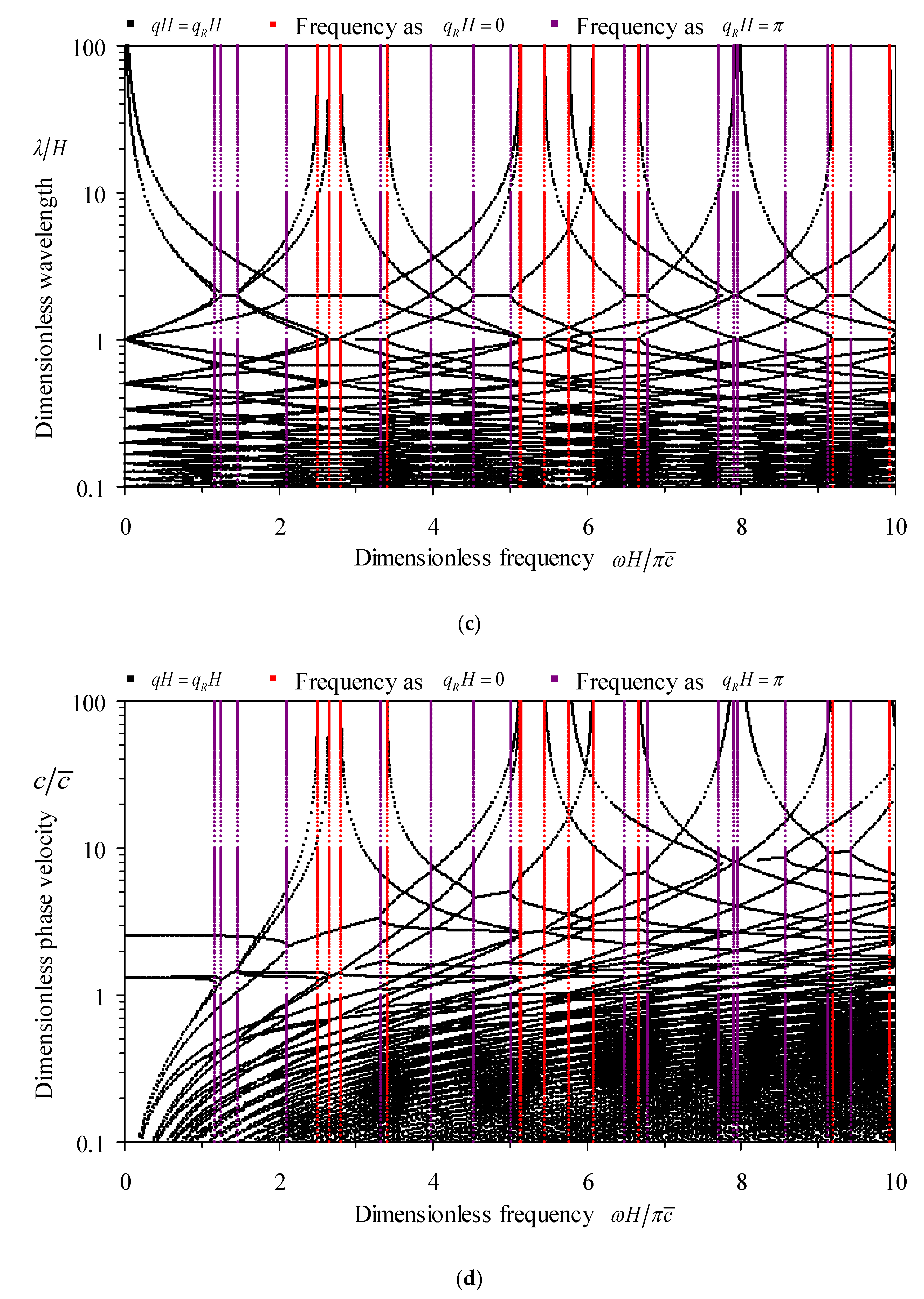
Table 1.
The mathematical formulas associated with various electrical boundaries 1–5.
| Electrical Boundaries | Electric-open | Applied capacitance | Electric-short | Applied feedback control |
| Associated Mathematical Formulas |
1 is the electric charge on one electrode; 2 is the voltage (electric potential difference) between electrodes; 3 is the applied capacitance; 4 is the gain coefficient in the feedback control system; 5 and are the displacements along the thickness direction on the top and bottom surfaces.
Table 2.
The involved expressions relative to electrical boundaries.
| Electrical Boundaries | Expressions of Scalar | Expressions of Scalar | Expressions of Vector |
|---|---|---|---|
| Electric-open | |||
| Applied capacitance | |||
| Electric-short | |||
| Applied feedback control | 1 | 1 | 1 |
1 .
Table 3.
Material parameters of the constituent layers in unit cell.
| Materials | PZT-5H1 | PZT-5H2 | Glass | Brass | |||
|---|---|---|---|---|---|---|---|
| Elastic constants | 12.600 | 7.421 | 8.334 | 16.246 | |||
| 12.600 | 12.600 | 8.334 | 16.246 | ||||
| 7.421 | 12.600 | 8.334 | 16.246 | ||||
| 7.950 | 8.410 | 2.300 | 8.258 | ||||
| 8.410 | 8.410 | 2.300 | 8.258 | ||||
| 8.410 | 7.950 | 2.300 | 8.258 | ||||
| 2.300 | 2.325 | 3.017 | 3.994 | ||||
| 2.300 | 2.300 | 3.017 | 3.994 | ||||
| 2.325 | 2.300 | 3.017 | 3.994 | ||||
| Piezoelectric constants | 17.000 | 17.000 | 0.000 (, ) | 0.000 (, ) | |||
| 17.000 | 17.000 | ||||||
| −6.500 | 19.200 | ||||||
| −6.500 | −6.500 | ||||||
| 19.200 | −6.500 | ||||||
| Dielectric constants | 150.518 | 83.300 | 0.354 | 0.000 | |||
| 150.518 | 150.518 | 0.354 | 0.000 | ||||
| 83.300 | 150.518 | 0.354 | 0.000 | ||||
| Material density | 7500 | 7500 | 2540 | 8320 | |||
© 2018 by the authors. Licensee MDPI, Basel, Switzerland. This article is an open access article distributed under the terms and conditions of the Creative Commons Attribution (CC BY) license (http://creativecommons.org/licenses/by/4.0/).
Share and Cite
MDPI and ACS Style
Li, Q.; Guo, Y.; Wang, J.; Chen, W. Band Structures Analysis of Elastic Waves Propagating along Thickness Direction in Periodically Laminated Piezoelectric Composites. Crystals 2018, 8, 351. https://doi.org/10.3390/cryst8090351
AMA Style
Li Q, Guo Y, Wang J, Chen W. Band Structures Analysis of Elastic Waves Propagating along Thickness Direction in Periodically Laminated Piezoelectric Composites. Crystals. 2018; 8(9):351. https://doi.org/10.3390/cryst8090351
Chicago/Turabian StyleLi, Qiangqiang, Yongqiang Guo, Jingya Wang, and Wei Chen. 2018. "Band Structures Analysis of Elastic Waves Propagating along Thickness Direction in Periodically Laminated Piezoelectric Composites" Crystals 8, no. 9: 351. https://doi.org/10.3390/cryst8090351
Note that from the first issue of 2016, this journal uses article numbers instead of page numbers. See further details here.