Why Do Secondary Cracks Preferentially Form in Hot-Rolled ODS Steels in Comparison with Hot-Extruded ODS Steels?


1
Helmholtz-Zentrum Dresden-Rossendorf, Bautzner Landstrasse 400, 01328 Dresden, Germany
2
Institute for Applied Materials, Karlsruhe Institute of Technology, Hermann-von-Helmholtz-Platz 1, 76344 Eggenstein-Leopoldshafen, Germany
*
Author to whom correspondence should be addressed.
Crystals 2018, 8(8), 306; https://doi.org/10.3390/cryst8080306
Submission received: 6 July 2018
/
Revised: 20 July 2018
/
Accepted: 23 July 2018
/
Published: 25 July 2018
(This article belongs to the Special Issue Nanostructured Ferritic Alloys)
Abstract
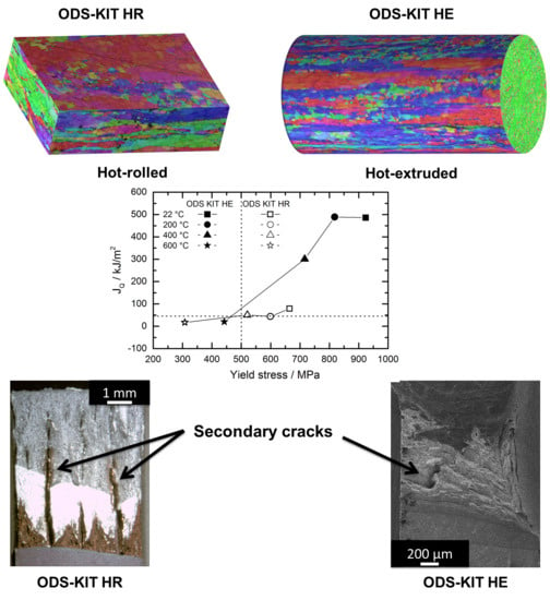
:Secondary cracks are known to absorb energy, retard primary crack propagation and initiate at lower loads than primary cracks. They are observed more often in hot-rolled than in hot-extruded ODS steels. In this work, the microstructural factors responsible for this observation are investigated. Better understanding of these factors can lead to tailoring of improved ODS steels. Fracture toughness testing of two batches of 13Cr ODS steel, one hot-rolled and the other hot-extruded, was carried out. The fracture behaviour of secondary cracks was investigated using scanning electron microscopy (SEM) and electron backscatter diffraction (EBSD). Crystallographic texture and grain morphology play a predominant role in preventing secondary cracks in hot-extruded ODS steels. At lower temperatures, secondary cracks occur predominantly via transgranular cleavage. The fracture mode changes to ductile and intergranular at higher temperatures.
1. Introduction
ODS steels are candidate materials for cladding tubes in advanced nuclear fission reactors and are candidate structural materials for fusion devices. Nanostructured ferritic alloys (NFAs) are variants of ODS steels consisting of finer microstructures, with Cr content more than 12 wt.%, nano-particles in the size range of 1–10 nm and grain sizes in the sub-micron range [1,2,3]. Secondary cracks are typical features indicating heterogeneous mechanical behavior and are often observed on the primary fracture surfaces of these materials in certain orientations. The secondary cracks propagate in a plane perpendicular to the primary crack plane and are formed due to constraint induced stress. They may appear under certain conditions due to the phenomenon of delamination [4,5,6,7,8], also known as splitting [4,6,9,10], which inhibits the primary crack propagation. The term delamination was derived from composites where it meant separation of different composite layers through an interfacial mechanism [11,12]. ODS steels possess different microstructural regions, which behave like different layers of a composite. However, there is usually no sharp transition between these microstructural regions.
Delamination can transpire in two configurations, the “crack-divider” and the “crack-arrester” geometries, both associated with hot-rolled specimens as shown in Figure 1 [13]. Secondary cracks seem to accompany delamination in certain sample orientations, such as L-T and T-L in hot-rolled materials, which are classified as crack divider geometries [13]. Crack divider geometries have a specific primary crack propagation direction with respect to the anisotropic microstructure. These secondary cracks divide the specimen thickness into sub-specimens (Figure 1a). The state of constraint near the primary crack is relaxed which retards the primary crack growth. Crack arrestor geometry, however, is associated with the L-S and T-S oriented samples in hot-rolled materials. In the crack arrester geometry, delamination deflects the primary crack through 90° and the fracture mode changes from mode I to mode II [4,14]. No secondary cracks are formed in the crack arrestor configuration (Figure 1b). It is noteworthy, that in some publications, secondary cracking and delamination are used as synonyms. In this work however, a clear distinction between the two is made. The delamination geometries used for hot-rolled specimens like crack arrestor and crack divider are usually not used for hot-extruded specimens.
It was reported that delamination, and the accompanied secondary cracking, can result in increased energy absorption [8,14,15,16]. Despite this, secondary cracks can also lead to design problems as they are known to initiate at lower loads than primary cracks [8,17].
In our previous work, the anisotropy of secondary cracks in the crack-divider geometry [13] of hot-rolled 13Cr ODS steel was discussed along with its effect on primary crack propagation [17]. Hot-extruded 13Cr ODS steel specimen on the other hand, as reported previously in [18], exhibited minor or no secondary cracking. Other works also corroborated that hot-rolled ODS steels exhibited greater propensity to secondary cracking [4,5,9,15,19,20,21] than hot-extruded ODS steels [9,21,22]. It is generally believed that weak planes are the primary cause for secondary cracks; however, the source of weak planes remains a point of debate [5,22,23,24]. A clear understanding why hot-rolled specimens experience greater secondary cracking than hot-extruded specimen is not known. Through this paper, we aim to throw light on this aspect by comparing microstructural features such as grain morphology and crystallographic texture of non-irradiated hot-rolled and hot-extruded materials.
Fracture toughness tests using miniature compact tension specimens (C(T)) of non-irradiated hot-rolled and hot-extruded 13Cr ODS steels were performed from −100 °C to 700 °C in different orientations. Scanning electron microscopy (SEM) was performed on primary and secondary crack fracture surfaces to reveal more information about the mode of fracture. SEM and electron backscatter diffraction (EBSD) were used to investigate the bulk microstructure.
2. Materials and Methods
2.1. Material
The 13%Cr ODS steels were provided by Karlsruhe Institute of Technology, Karlsruhe, Germany (KIT) in hot-extruded rod and in hot-rolled plate forms. The nominal composition of the material was 13Cr1W0.3Ti0.3Y2O3. The main production steps for manufacturing the hot-rolled plate were the following: mechanical alloying of the steel alloy and 0.3% Y2O3 powder in an attritor ball mill, encapsulation of the powder, evacuation of the capsule and hot isostatic pressing at 1100 °C and 100 MPa and rolling at 1100 °C from a diameter of 80 mm to a plate of 8 mm thickness in 5 runs. The main manufacturing steps for the hot-extruded rod were the following: mechanical alloying of the steel alloy and 0.3% Y2O3 powder in an attritor ball mill, encapsulation of the powder, evacuation of the capsule and hot-extrusion at 1100 °C. The reduction of 80 mm initial diameter to a 12 mm final diameter rod resulted in an extrusion ratio of 44.4. Details of the production method for both the materials can be found in reference [25].
For simplification, the terms ODS-KIT HR and ODS-KIT HE will be used throughout this work to represent hot-rolled 13Cr ODS steel and hot-extruded 13Cr ODS steel from KIT respectively. The bulk composition of the material can be found in reference [18].
2.2. Fracture Mechanics Specimens
Miniature compact tension C(T) specimen of 6.35 mm (0.25 T) thickness were machined from the hot-rolled material while C(T) specimen of 4 mm thickness (0.16 T) were machined from the hot-extruded material. The cutting schemes of the specimens along with the different orientations can be seen in Figure 2 and were also reported in references [17,18]. All the C(T) specimens were 20% side grooved and fatigue pre-cracked at room temperature to a crack length to width ratio (a/W) of 0.5 using a resonance testing machine. The nominal cyclic stress intensity at the end of fatigue pre-cracking stage (Kend) was 14 MPa√m.
2.3. Quasi-Static Fracture Toughness Testing
Quasi-static fracture toughness tests were carried out on small size C(T) specimens using the unloading compliance method [26]. The unloadings were carried out with a 25% load drop and a 30 s relaxation time. Single tests were performed in air for ODS-KIT HE at temperatures of 22, 200, 400, 600 °C. For ODS-KIT HR, the same test plan as ODS-KIT HE was adopted with additional single tests at −100 °C, 100 °C, 500 °C and 700 °C. The crosshead speed of the machine was 0.1 mm per minute with unloading steps of 0.015 mm. The tests were stopped after approximately 1 mm crack propagation and thereafter the specimens were heat tinted. The tests performed at or above 400 °C required no additional heat tinting due to the high test temperature. The primary fracture surfaces were revealed by breaking open the C(T) specimen after dipping it in liquid nitrogen. The initial and the final primary crack lengths were measured at the fracture surfaces using optical microscope according to the nine point standard ASTM method [27]. For the 0.16 T specimens (ODS-KIT HE), the crack opening displacement (COD) measurements were performed on the load line using a contact clip on gauge in the temperature range from RT to 200 °C. From 200 °C to 600 °C, a contactless video extensometer was used at the front face. For 0.25 T specimens (ODS-KIT HR), front face displacement measurement was performed at all temperatures. For all the front face displacement measurements, the compliance and the displacement values were converted to the load line values [28]. There after the evaluation was performed according to ASTM E1820-13 [27].
2.4. Microscopy
2.4.1. Basic Characterization
Electron backscatter diffraction (EBSD) was performed to obtain information about crystallographic texture and grain distribution. The samples were polished using an oxide polishing suspension (OP-S) consisting of amorphous silica, water and 1,3 butanediol. For EBSD, an accelerating voltage of 20 kV and a working distance of 18 mm were used. The image resolution was fixed at 800 × 600 as a trade-off between total image acquisition time and a sufficiently high degree of detail. The step size was varied between 48 nm and 0.19 µm depending on the field of view. A large field of view was needed for basic microstructure analysis to obtain a statistically large ensemble of grains while a small field of view was required for crack propagation analysis. Inverse pole figure maps were acquired to identify the grain size, morphology and orientation. Noting that the materials are ferritic and that high-angle boundaries (as opposed to low-angle boundaries) generally play a dominant role in fracture [29], this study is focused on high-angle boundaries and the minimum misorientation angle for the EBSD analysis was arbitrarily fixed at 10°. Inverse pole figures were also acquired for specific planes which indicate the intensity of textures on these planes.
2.4.2 Fracture Surface and Crack Propagation
After fracture mechanics testing, few samples were cut in half though the thickness direction (LT plane) to utilize them for primary crack propagation imaging (−100 °C) and have been published elsewhere [17]. SEM was performed on all primary fracture surfaces after breaking the samples open. In some cases, secondary cracks were observed on the primary crack plane. EBSD misorientation line scan analysis was performed across such secondary cracks on subsequently polished planes either parallel or perpendicular to the primary crack plane. It is possible to perform the misorientation line scan with respect to the immediately previous point or with respect to the first measurement point. It was decided to perform the line scan using the former as in order to obtain the misorientation across a crack, we require the misorientation with respect to the previous point. The misorientation line scan with respect to the immediately previous point exhibits sharp peaks when the orientation changes. The magnitude of the peaks is the misorientation between two grains or across the crack. In other cases, the secondary cracks were opened up for fracture surface investigations using SEM.
3. Results
3.1. Basic Characterization of The Microstructure
Nano-particles in the size range of 1 to 10 nm are found in both the materials with their spatial distribution being inhomogeneous [17,18]. The material contains zones of high and low number density of sub-micron Ti-enriched particles. These particles have a mean size of 60 nm and are preferentially arranged in lines parallel to the rolling (Figure 3a) [10] or extrusion direction (Figure 3c) [15]. Additionally, in ODS-KIT HR, the sub-micron particles are also arranged in lines parallel to the transverse direction (Figure 3b) [30]. Some holes in Figure 3 are slightly larger than the holes induced by the fallout of particles and are most likely pre-existing pores in the material. The pre-existing pores also seem to follow the same arrangement as particles.
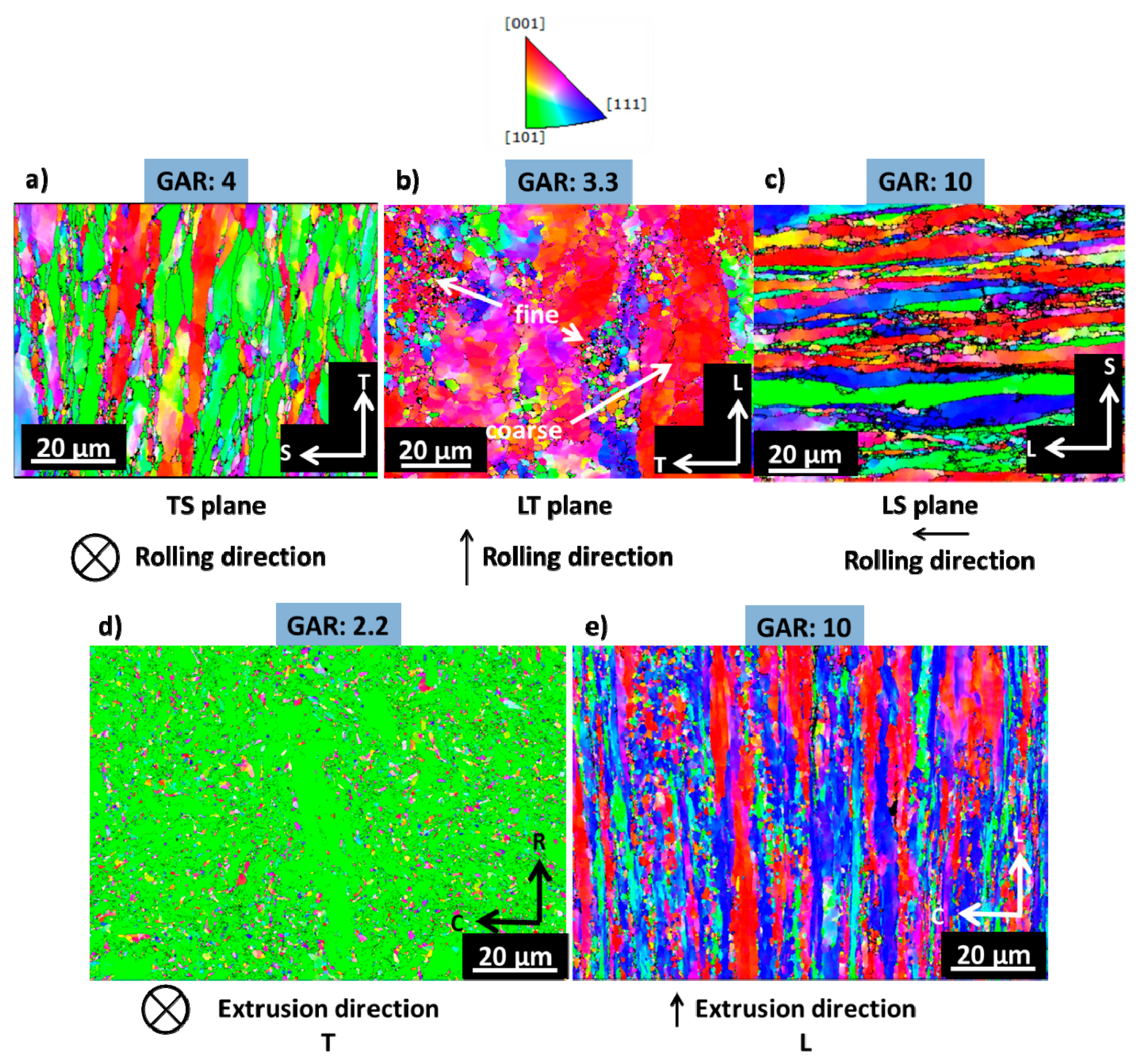
Inverse pole figure Z maps, which provide information about the grain morphology and crystallographic texture, are shown for both materials in Figure 4. Fine-grained zones typically alternate with coarse-grained zones. A detailed statistical grain size analysis in terms of average grain size and grain aspect ratio (GAR) is presented in Table 1 and Table 2 for fine and coarse grains, respectively. The coarse grains in ODS-KIT HR are ‘pancake’-shaped and have maximum arrangement and elongation of grains in the L direction followed by the T and S directions. ODS-KIT HE contains zones of ‘cigar’-shaped coarse grains (>3 µm). Both the individual coarse grains and the zones are elongated in the extrusion direction. The fine-grained zones in both materials exhibit similar shape and arrangement as the coarse-grained zones. A significant fraction of the fine grains are ultra-fine grains with sizes less than 1 µm. The GAR of the individual fine grains is smaller than the GAR for the coarse grains.
The Z plot of inverse pole figures in Figure 5a shows a high intensity of [001] for ODS-KIT HR, which means that many grains are aligned with their <100> directions parallel to the normal of the rolling plane (LT). This also means that {100} planes of the grains are parallel to the rolling plane. The Y plot shows a high intensity of [101], which means that a large number of grains are oriented with the <110> directions parallel to the rolling direction. This combination of {100} <110> with respect to the rolling direction is called α fibre texture. For ODS-KIT HE, the Z plot in Figure 5b shows some intensity of [111] and a minor intensity of [001] while the Y plot shows a very high intensity of [101]. Therefore, in ODS-KIT HE, a strong texture with grains oriented with the <110> directions parallel to extrusion direction is observed, as also found for ODS-KIT HR, but the {100} planes of the grains are not parallel to any specific plane.
3.2. Fracture Toughness Tests
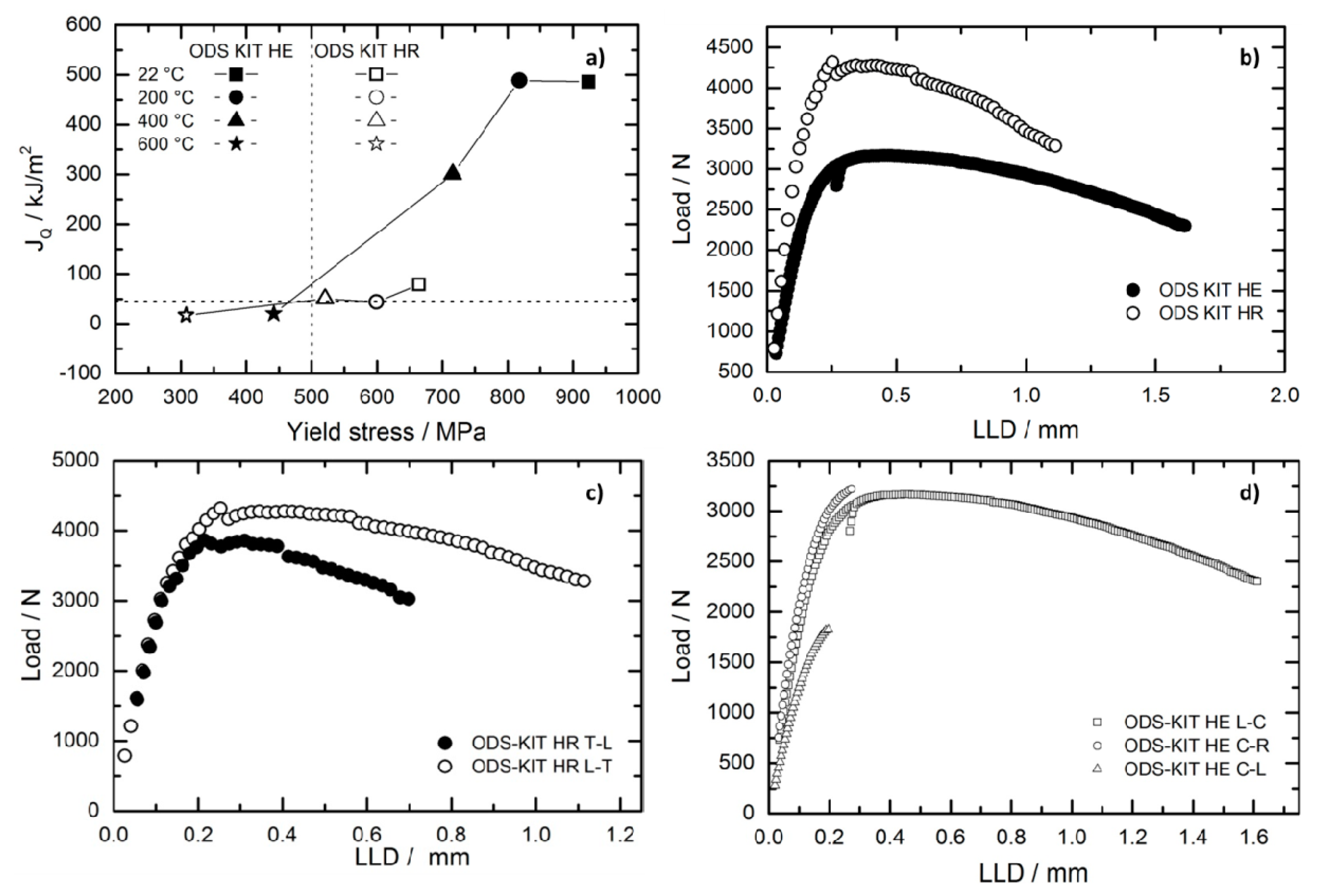
The fracture toughness in the strongest orientation (L-T for ODS-KIT HR and L-C for ODS-KIT HE) is plotted against the yield strength at different temperatures and is presented in Figure 6a. The fracture toughness is represented by JQ values which are provisional JIC values determined by the intersection of the J-R curve with a 0.2 mm offset line. The fracture toughness values of ODS-KIT HR and ODS-KIT HE were published in references [17,18] and are again presented in Table 3 Even though the C(T) specimens from the two materials differed in size, it did not make an appreciable difference to the fracture toughness measurement as the plastic zone in front of the crack tip was small enough in comparison to the size of the specimen.
ODS-KIT HE exhibits overall higher fracture toughness than ODS-KIT HR in all the orientations (Table 3 and Figure 6a) from RT to 400 °C. Both the materials have yield strength higher than 500 MPa in this temperature range. Between 400 °C and 600 °C, both the materials lose fracture toughness steeply and drop below the acceptable limit of JQ = 45 kJ/m2 (KJQ = 100 MPa√m) as discussed by Byun et al. [31] (Figure 6a). The yield strengths of both the materials also sink below 500 MPa. Unstable crack propagation was experienced by ODS-KIT HR in the T-L orientation at 200 °C, 400 °C and 500 °C (suffixed with U in Table 3) while in ODS-KIT HE, it took place at RT in the C-R and C-L orientations.
The load versus load line displacement graph at RT (Figure 6b) shows that the maximum load reached for ODS-KIT HR is higher than ODS-KIT HE during the test. A higher maximum load means higher main stress which results in a higher constraint induced stress experienced by the specimen. However, the area under the graph is higher for ODS-KIT HE. The load versus load line displacement curve for ODS-KIT HR at RT (Figure 6c) shows that the maximum load for the L-T orientation is slightly higher than the T-L orientation. The area under the curve for the L-T orientation is also larger than for the T-L orientation. The load versus load line displacement curve for ODS-KIT HE at RT (Figure 6d) shows that the maximum load for the L-C and the C-R orientation are similar and higher than for the C-L orientation. The area under the graph for the L-C orientation is the highest while the area under the graph for the C-R and the C-L orientations are much lower (considering there was unstable crack propagation in the C-R and the C-L orientations at RT).
3.3. Primary Fracture Surfaces
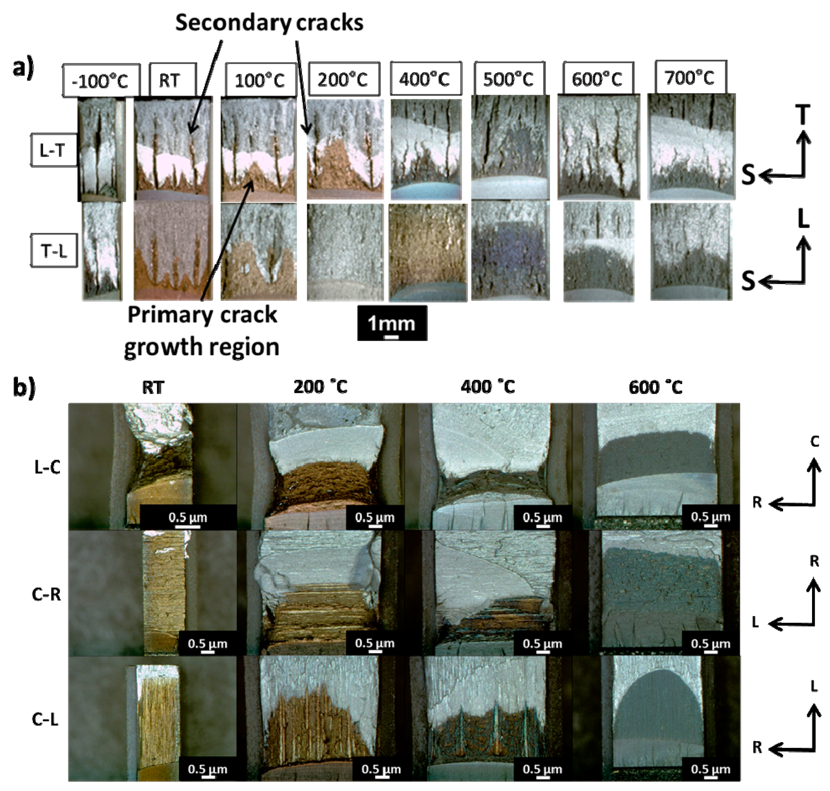
The macroscopic images of the fracture surfaces of both the materials in all the orientations and at various test temperatures are presented in Figure 7. The green region is formed due to heat tinting and represents the primary crack growth region. Secondary cracks, growing in a plane perpendicular to the primary crack plane and running ahead of the primary crack are observed in ODS-KIT HR as can be seen from Figure 7a. This part of the figure was already published in [17] and is presented here for comparison. For the L-T orientation, secondary cracks are observed at all temperatures. At higher temperatures, the extent of secondary cracks decreases. For the T-L orientation, lesser secondary cracks are observed. Unstable primary crack propagation occurred in the T-L orientation at 200 °C, 400 °C and 500 °C, as was already mentioned.
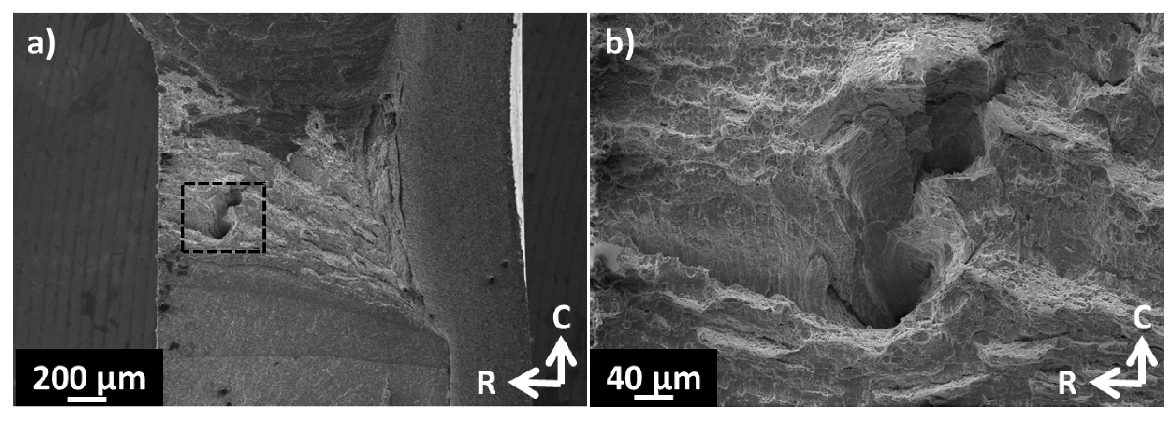
In ODS-KIT HE, the primary crack propagated unstably in the orientations C-R and C-L at RT (Figure 7b). Only minor secondary cracking is observed on the fracture surfaces of ODS-KIT HE in all the orientations and at all temperatures. The periodic steps visible on the primary fracture surfaces of C-R and C-L orientation at 200 °C and 400 °C are not secondary cracks but large dimpled regions formed due to the anisotropy in arrangement of void inducing particles [30]. More details can be found in the supplementary material. A partially arrested secondary crack is seen on the fracture surface of the L-C oriented specimen at RT (Figure 8a). Figure 8b shows a higher magnification SEM image of the same. More information about the primary fracture surfaces of both the materials can be found in references [17,18].
3.4. Secondary Fracture Surfaces
The secondary cracks were broken apart and investigated using SEM. Stereo-microscopic and SEM micrographs taken for samples tested at different temperatures are summarized in Figure 9 for the L-T orientation. The notch is on the right of all the images and the primary crack propagates towards the T direction. Secondary cracks initiate at the TS plane and then propagate in the L (depth) and the T (in-plane) directions. At RT, the presence of a predominantly cleavage fracture surface with some regions of dimples is observed (Figure 9a–c). At 200 °C, dimples (Figure 9d–f) and at 600 °C, nano-features without dimples are predominantly observed on the fracture surface (Figure 9g–i).
3.5. EBSD Misorientation Analysis
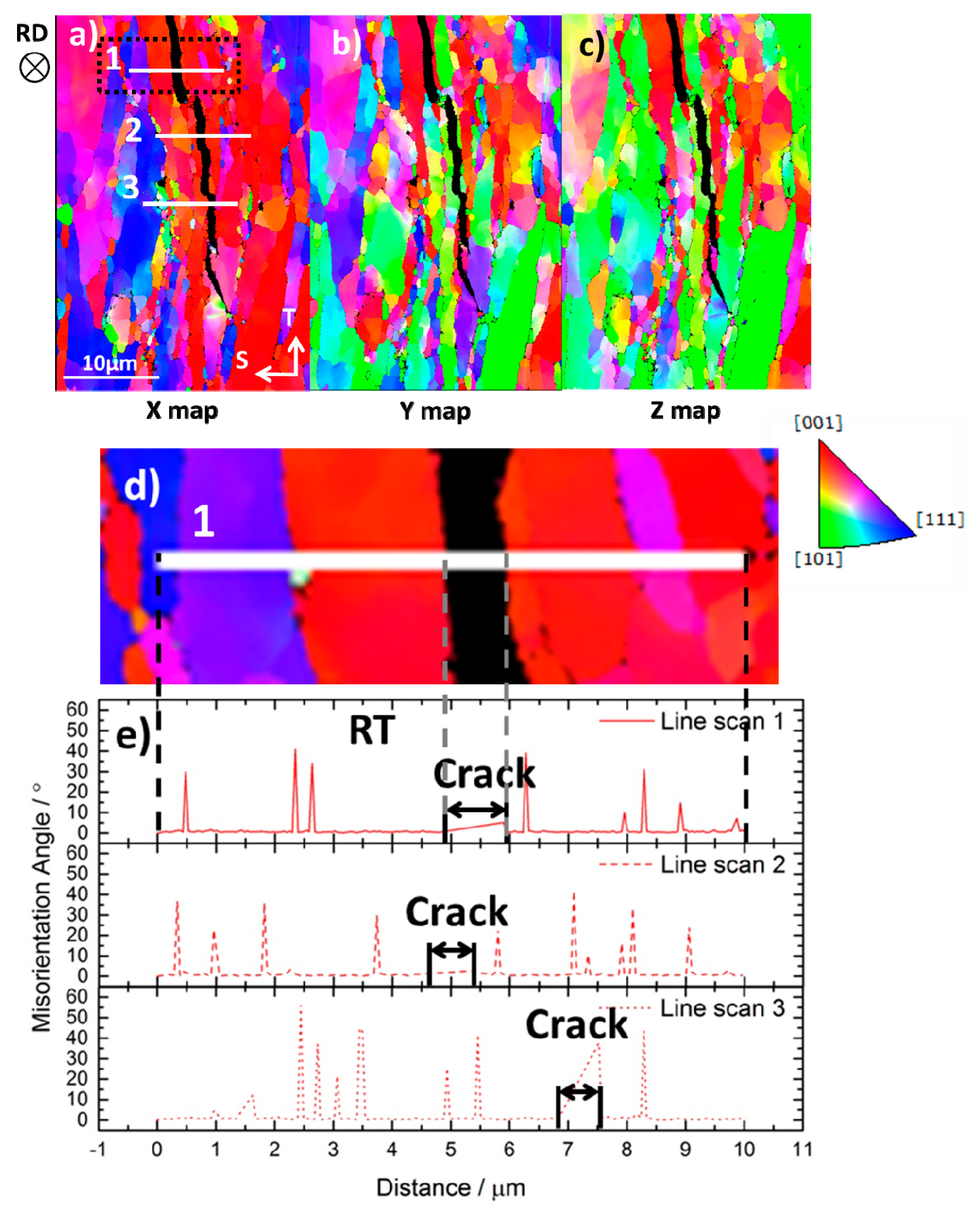
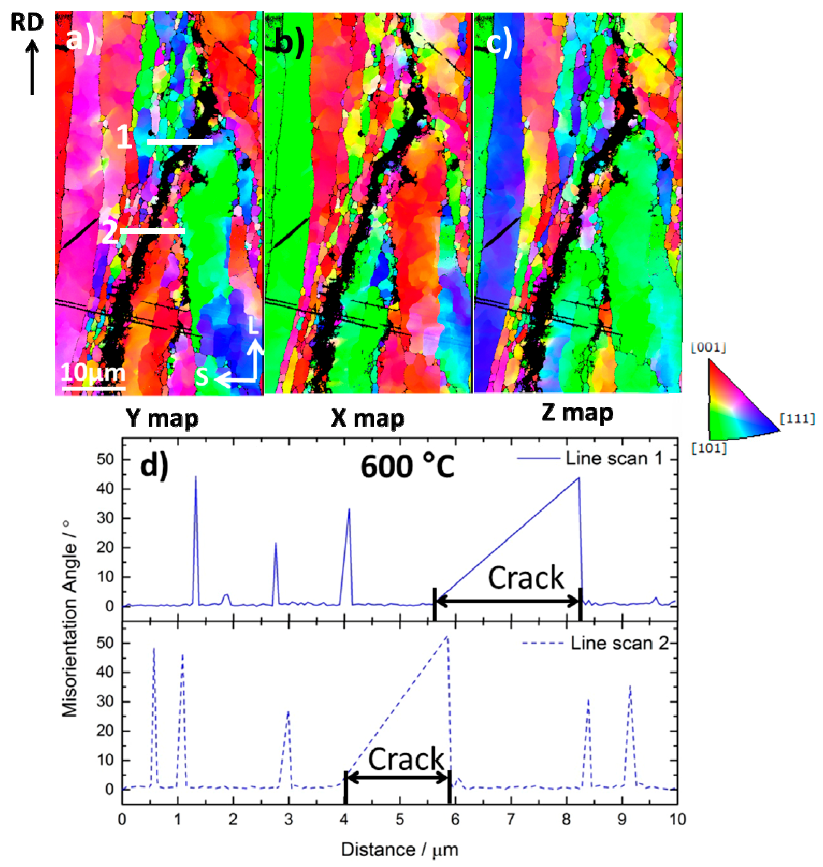
EBSD IPF maps (X, Y and Z maps) of the TS plane (a plane parallel to primary crack plane and containing a secondary crack) at RT and LS plane (a plane perpendicular to both the primary and secondary crack planes and containing a secondary crack) at 600 °C for a L-T oriented specimens are shown in Figure 10 and Figure 11, respectively. Here the X, Y and Z maps, which belong to the same secondary crack, reveal the complete information about the three dimensional grain orientations across the crack. Three lines scans were performed for the crack at RT (Figure 10e) and two for the crack at 600 °C (Figure 11d). The misorientation line scans with respect to the immediately previous point indicates that at RT, there are several locations across the crack where the misorientation angle changes by 5 degrees or less (line scans 1 and 2 in Figure 10). One such example (line scan 1) is magnified in Figure 10d. There are also few locations, where the misorientation angle changes by more than 15 degrees (line scan 3 in Figure 10a). At 600 °C, the locations of low misorientation across the secondary crack (<5°) are not observed and only high misorientations exists (Figure 11). The situation was found to be similar for T-L oriented specimens.
With respect to the morphology of the secondary crack as seen from the side, the crack edges at RT appear straighter with sharper features than at 600 °C. Similar sharp features were also observed for other ODS-KIT HR specimens at similar testing conditions close to RT.
4. Discussion
The higher fracture toughness of ODS-KIT HE as compared with ODS-KIT HR (Figure 6a and Table 3) stems predominantly from the grain morphology. Elongated coarse grains perpendicular to the crack propagation direction leads to crack blunting which increases the fracture toughness in certain orientations [17]. ODS-KIT HE has ‘cigar’ like coarse grains elongated only in one direction (the extrusion direction) while ODS-KIT HR has ‘pan-cake’ like coarse grains elongated in two directions (rolling and transverse directions). This results in lesser resistance to crack propagation in hot-rolled specimens than in hot-extruded specimens which is reflected in Figure 6b showing lower ductility or lesser area under the curve for hot-rolled than hot-extruded specimen.
It is worth mentioning that in this work, due to material and geometrical limitations, hot-rolled specimens only with “crack-divider” geometries (L-T and T-L) were investigated which typically have lower fracture toughness than hot-rolled specimens with “crack-arrestor” geometries (e.g., L-S and T-S) [13]. However, the main focus of this paper is on secondary cracks, which can be clearly understood using the crack-divider geometry in hot-rolled specimens. The crack-arrestor geometry induces no secondary cracks. For hot-extruded specimens, the terms crack divider and crack arrestor are typically not used.
4.1. General Factors Affecting Secondary Cracking
Secondary cracks form in a similar fashion as primary cracks, by cleavage fracture at low temperatures and by void growth and coalescence in the ductile regime. Ashby [32] had suggested that, void nucleation due to particle-matrix decohesion occurs when a critical stress is reached at the particle-matrix interface. For ductile fracture, when the constraint induced stress (σc) exceeds the critical stress for void nucleation (σf) in a particular plane, secondary cracks appear (Equation (1)). σf can also be referred to as the critical stress for particle cracking in case of cleavage fracture at low temperatures.
σc > σf
Both these competing stresses can be affected by the microstructural anisotropy in the material. The three main microstructural anisotropic factors which affect secondary cracking are the same factors which affect primary crack propagation [18]. These factors are:
- Particle anisotropy: Particles are arranged in the direction of the rolling/extrusion and hence facilitate crack propagation by cleavage or by void growth and coalescence depending on the test temperature.
- Crystallographic anisotropy: Due to the <110> texture induced in the direction of the rolling/extrusion, the shear modulus with respect to the longitudinal direction is different from the isotropic transverse direction.
- Grain morphology anisotropy: Coarse grains are elongated in the direction of the rolling/extrusion which results in crack blunting when the propagating crack is obstructed by the perpendicularly elongated coarse grains.
The following sub-sections discuss if the same anisotropic factors are important for the present set of materials and if yes, to what extent. In the end, a comparison is made and how secondary cracking differ in hot-rolled and hot-extruded materials is explained.
4.2. Understanding of Secondary Cracking in Hot-Rolled ODS Steels
4.2.1. Effect of Crystallographic Texture
For ODS-KIT HR, the secondary cracks propagate through the LT plane in both the L-T and T-L oriented specimens (Figure 2a). In terms of crystallographic orientation, ODS-KIT HR possesses an α fibre texture of {100} <110> (Figure 4a–c). It was reported that for body-centered cubic (BCC) polycrystalline materials with such texture, the material does not deform axisymmetrically but tends to deform by plane strain under uniaxial tensile stress along the <110> direction [4]. As a result of this, tensile stresses in {100} planes (parallel to the rolling plane LT) and compressive stresses in {110} planes (parallel to the rolling direction) are generated [33,34] which have an absolute value in the order of 1/5 and 1/3 of the material flow stress respectively [35,36]. In a BCC crystal, the most preferable cleavage planes are the {100} planes. Therefore at low temperatures, the tensile stresses arising from the plane strain condition cleave the {100} planes, aligned parallel to rolling plane (Figure 5a). As the secondary crack planes (LT planes in Figure 2a) are parallel to the cleavage planes, secondary cracks appear [37].
At higher temperatures (ductile regime), it was reported that void growth and coalescence is preferred in the <110> direction which helps secondary crack formation towards the rolling direction (L) [38]. The arrangement of Ti enriched sub-micron particles along the rolling and transverse directions also helps in void growth and coalescence (Figure 3a,b) [30]. Pre-existing pores and microcracks elongated in the direction of the rolling direction additionally contributes to secondary cracking, as reported in reference [14].
4.2.2. Effect of Grain Morphology
It was reported that the anisotropic grain morphology predominantly affects the primary crack propagation [18]. The effect is the same for secondary crack propagation. The coarse grains are elongated in the L and T directions, the former more than the latter, leading to less crack blunting and easier crack propagation in these directions. The secondary cracks propagate through the ultra-fine grains similar to primary cracks as was reported in reference [17]. For the secondary crack propagation in the L-T specimen, the crack must propagate in the L (depth) and in the T (in-plane) directions (Figure 2a). For the T-L oriented specimens, the directions inter-change but the fracture plane remains the same (LT). The crack now propagates in the T direction (depth) and L direction (in-plane). As crack propagation in these directions are less obstructed (due to less crack blunting), the critical fracture stress σf is low for the LT plane and crack blunting is less pronounced. The constraint induced stress σc is high enough to overcome the critical fracture stress in both the orientations (Equation (1)). Thus, ODS-KIT HR in the L-T and the T-L orientations is majorly affected by secondary cracking. The higher constraint induced stress in the L-T orientation (Figure 6c) results in more pronounced secondary cracking in the L-T orientation as compared with the T-L orientation [17].
4.2.3. Fracture Mechanisms
Secondary cracks initiated earlier than the primary cracks [8,17] at lower loads due to the ease of crack propagation in the secondary crack plane than in the primary crack plane [17]. To further explore the fracture mechanisms associated with secondary cracking, EBSD misorientation line scans were performed across a secondary crack lying on a plane perpendicular to the secondary crack plane. Results indicate that the secondary crack was sometimes transgranular (low misorientation angle <5°) (line scans 1 and 2 in Figure 10) and sometimes intergranular (high misorientation angle >5°) (line scan 3 in Figure 10) at RT while always intergranular at 600 °C (Figure 11). The low angle misorientations hint to the possibility of either or both transgranular cleavage and transgranular ductile fracture mechanisms. The presence of both cleavage and dimpled fracture is confirmed by SEM images of the secondary crack surface at RT (Figure 9a–c). Regions of flat cleavage facets mixed with regions of shallow dimples indicate local variations in the stresses during crack propagation. The fact that the side view of the secondary crack has predominantly sharp edges (Figure 10), suggests the preference of cleavage over ductile fracture at low temperatures. Regions of high misorientation angles at RT indicate intergranular fracture and possibly originate due to grain boundary segregations as was reported in other works [5,22,24,39]. The ratio of shear to bulk modulus also plays a role in the preference of intergranular over cleavage fracture [40]. Due to the elongated coarse grains, intergranular fracture with typical sharp facets was not observed on the fracture surfaces. Existence of dimples (Figure 9d–f) on the fracture surface at the test temperature of 200 °C indicates that the material is already in its ductile regime. The high angle misorientations at a test temperature of 600 °C (Figure 11) are observed due to intergranular fracture caused by grain boundary sliding or grain matrix deformation phenomena as reported in a previous work [41]. The side view of the crack does not exhibit sharp edges at 600 °C (Figure 11) and exhibits nano-features on the secondary crack surface (Figure 9g–i) confirming a change of fracture mechanism from transgranular to intergranular fracture.
4.3. Understanding of Secondary Cracking in Hot-Extruded ODS Steels
For hot-extruded materials, the constraint induced stress is the highest in the L-C oriented specimens. This is due to the high main stresses in the L-C orientation (Figure 6d) as a consequence of the higher primary crack blunting (higher fracture toughness) in this orientation [18]. In the L-C orientation, the primary fracture plane is the CR plane (Figure 2b). The secondary crack initiating on this plane will propagate in the C (in-plane) and L (depth) directions. Void nucleation and growth in the ductile regime is easiest along the extrusion direction (L) due to arrangement of sub-micron particles [18]. <110> crystallographic texture with respect to the extrusion direction (Figure 4d,e) [38] and UFG zones elongated in the extrusion direction also aid the crack propagation in the L direction [18]. Due to these reasons, the secondary crack can grow easily in depth (L) direction but, finds it difficult to propagate in the in-plane (C) direction. As secondary crack propagation in both directions is inter-dependent, this results in a large critical fracture stress (σf) on the CL plane. The high constraint induced stress (σc) in the L-C orientation (Figure 6d) is only partially able to overcome it at some locations (Equation (1)). As soon as a secondary crack forms, σc drops below σf, arresting the secondary crack. Partially formed secondary cracks are therefore arrested in the in-plane (C) direction (Figure 8). At low temperatures, transgranular cleavage should dominate, but only a few grains with {100} cleavage planes parallel to secondary crack planes are observed. This is due to the general symmetry of hot-extruded materials where grains with {100} cleavage planes are distributed uniformly around the extrusion axis. Therefore, cleavage fracture for secondary cracks is prevented up to a relatively low temperature as compared with ODS-KIT HR.
In the C-R orientation, the constraint induced stress (σc) is similar to that of the L-C orientation (Figure 6d). The primary fracture plane is the RL plane (Figure 2b). The secondary crack initiating on this plane will propagate in the R (in-plane) and the C (depth) directions. Secondary crack propagation is difficult in both these directions as there is no preferential alignment of sub-micron particles or ultra-fine grains along these directions and there is also no preferential crystallographic orientation along these directions. Hence the critical fracture stress (σf) for secondary cracks is the highest for the RL plane. The constraint induced stress σc cannot exceed the high σf and no secondary cracks are seen (Equation (1) is not fulfilled).
In the C-L orientation, the constraint induced stress is lower as compared with the L-C orientation (Figure 6d). The primary fracture plane is the LR plane (Figure 2b). The secondary crack initiating on this plane will propagate in the L (in-plane) and the C (depth) directions. Crack propagation is easier in the in-plane L direction but difficult in the depth C direction. The critical fracture stress (σf) is low in the C-L orientation but due to the lower constraint induced stresses (σc), Equation (1) is not fulfilled and no secondary cracks are formed.
4.4. Comparison
Previous works confirm that the hot-extruded materials have lesser propensity to secondary cracking than hot-rolled materials [9,10,21,22,42]. The difference in secondary cracking between ODS-KIT HR and ODS-KIT HE originates from the following factors:
Crystallographic texture: In ODS-KIT HR, the {100} cleavage planes, which assists cleavage fracture at low temperatures, are parallel to the rolling plane. This is the same plane where the secondary cracks operate. This is not the case in ODS-KIT HE, where due to the manufacturing process, the {100} cleavage planes are uniformly distributed around the extrusion axis. The <110> texture in the direction of rolling/extrusion on the other hand, affects both the materials similarly.
Grain morphology: In ODS-KIT HR, the critical fracture stresses for secondary crack initiation are lower due to two dimensional anisotropic grain elongations in the rolling and the transverse direction. This favours free crack propagation in two directions which coincides with the directions of secondary crack propagation. In ODS-KIT HE, only one dimensional anisotropic grain elongation in the direction of extrusion exists which is unable to support pronounced secondary cracking.
Particle distribution: The sub-micron particles responsible for void growth and coalescence in the ductile regime are arranged in the rolling/extrusion direction for both the materials. In ODS-KIT HR, the sub-micron particles are also arranged along the transverse direction providing additional support for the secondary crack formation (Figure 3b). This effect is in synergy with the effect by anisotropic grain morphology [30].
Additionally, the constraint induced stress in ODS-KIT HR is higher than in ODS-KIT HE (Figure 6b). This is because the ODS-KIT HR specimens are thicker (0.25T C(T)) than the ODS-KIT HE specimens (0.16T C(T)). The higher the constraint induced stress is, the higher the possibility of secondary cracking is. Hence, overall, hot-rolled materials are more prone to secondary cracking than hot-extruded materials. The consequence of partial or no secondary crack formation in hot-extruded specimen is unstable primary crack propagation induced by transgranular cleavage which was observed in the C-R and C-L orientations at RT. In hot-rolled specimens, secondary cracks prevent unstable crack propagation at low temperatures as reported earlier [17].
Which of the above mentioned factors is dominantly responsible for pronounced secondary cracking in ODS-KIT HR depends on the testing temperature with respect to the ductile to brittle transition temperature (DBTT) of the material. At test temperatures lower than the DBTT, the {100} cleavage planes play a dominant role. At test temperatures above DBTT, the anisotropic grain morphology plays a major role while anisotropic particle distribution provides only a minor contribution [18].
It must be noted however, that impact testing to determine the DBTT could not be performed since a large amount of material was unavailable. Small punch tests (SPT) were used alternatively to investigate the DBTT and the results confirmed that ODS-KIT HE had a higher DBTT than ODS-KIT HR. A comparative study will be published in the future. It is noteworthy however, that SPT only gives an indication about the comparative DBTT of the materials and cannot be directly compared with the traditional Charpy V notch DBTT values.
5. Conclusions
- At temperatures below the DBTT, the occurrence of secondary cracks in hot-rolled materials is assisted by the {100} cleavage planes which are aligned parallel to the rolling plane. In hot-extruded materials, these {100} cleavage planes are distributed uniformly around the extrusion axis, therefore not assisting secondary cracking.
- At temperatures higher than the DBTT, secondary cracking is more frequent in hot-rolled than in hot-extruded materials as the critical fracture stresses in secondary crack planes are lower due to the two dimensionally anisotropic elongated ‘pan-cake’ shaped grains which allows free crack propagation in two directions. In hot-extruded materials, the one dimensional ‘cigar’ like grain morphology with grains elongated in the direction of extrusion only allows free crack propagation in one direction and hence does not assist secondary cracking as much.
- Sub-micron particle arrangement in two directions assists secondary cracking more in hot-rolled material than one dimensional sub-micron particle arrangement in hot-extruded material.
- The constraint induced stress in hot-rolled materials is higher than in hot-extruded materials which also assists a higher degree of secondary cracking.
- In ODS-KIT HR at RT, secondary cracking arise predominantly through transgranular cleavage and intergranular fracture possibly due to segregations at the grain boundaries. Between RT and 600 °C, secondary cracking occurs through transgranular ductile fracture and at or above 600 °C, secondary cracking occurs through intergranular fracture due to the weakening of the grain boundaries.
Supplementary Materials
Supplementary File 1Author Contributions
Conceptualization, A.D.; Methodology, A.D. and H.-W.V.; Software, A.D. and H.-W.V.; Validation, H.-W.V., E.A. and F.B.; Formal Analysis, H.-W.V.; Investigation, A.D., E.A. and F.B.; Resources, J.H.; Data Curation, A.D. and H.-W.V.; Writing-Original Draft Preparation, A.D.; Writing-Review & Editing, H.-W.V., E.A. and F.B.; Visualization, A.D., H.-W.V., E.A. and F.B.; Supervision, H.-W.V. and E.A.; Project Administration, E.A.; Funding Acquisition, E.A.
Acknowledgments
The authors would like to thank Wolfgang Webersinke and Mario Houska for their contributions to the fracture mechanics testing of C(T) specimens, Gudrun Müller for her contributions to EBSD & SEM investigations and Michaela Rossner for metallographic preparations. Additional thanks goes to our colleagues at the workshop. This work contributes to the pilot project FRACTO of the Joint Programme on Nuclear Materials (JPNM) from the European Energy Research Alliance (EERA).
Conflicts of Interest
The authors declare no conflict of interest.
References
- Odette, G.R. Recent progress in developing and qualifying nanostructured ferritic alloys for advanced fission and fusion applications. JOM 2014, 66, 2427–2441. [Google Scholar] [CrossRef]
- Byun, T.S.; Yoon, J.H.; Wee, S.H.; Hoelzer, D.T.; Maloy, S.A. Fracture behavior of 9Cr nanostructured ferritic alloy with improved fracture toughness. J. Nucl. Mater. 2014, 449, 39–48. [Google Scholar] [CrossRef]
- Oksiuta, Z.; Hosemann, P.; Vogel, S.C.; Baluc, N. Microstructure examination of Fe-14Cr ODS ferritic steels produced through different processing routes. J. Nucl. Mater. 2014, 451, 320–327. [Google Scholar] [CrossRef]
- Chao, J.; Capdevila, C.; Serrano, M.; Garcia-Junceda, A.; Jimenez, J.A.; Pimentel, G.; Urones-Garrote, E. Notch impact behavior of oxide-dispersion-strengthened (ODS) Fe20Cr5Al alloy. Metall. Mater. Trans. A 2013, 44, 4581–4594. [Google Scholar] [CrossRef]
- Serrano, M.; García-Junceda, A.; Hernández, R.; Mayoral, M.H. On anisotropy of ferritic ODS alloys. Mater. Sci. Technol. 2014, 30, 1664–1668. [Google Scholar] [CrossRef]
- Bramfitt, B.L.; Marder, A.R. A study of the delamination behavior of a very low-carbon steel. Metall. Trans. A 1977, 8, 1263–1273. [Google Scholar] [CrossRef]
- Bourell, D.L. Cleavage delamination in impact tested warm-rolled steel. Metall. Trans. A 1983, 14, 2487–2496. [Google Scholar] [CrossRef]
- Rao, K.V.; Ritchie, R.O. Mechanisms influencing the cryogenic fracture-toughness behavior of aluminum-lithium alloys. Acta Metall. Mater. 1990, 38, 2309–2326. [Google Scholar] [CrossRef]
- Hadraba, H.; Fournier, B.; Stratil, L.; Malaplate, J.; Rouffié, A.-L.; Wident, P.; Ziolek, L.; Béchade, J.-L. Influence of microstructure on impact properties of 9–18%Cr ODS steels for fusion/fission applications. J. Nucl. Mater. 2011, 411, 112–118. [Google Scholar] [CrossRef]
- Serrano, M.; Hernández-Mayoral, M.; García-Junceda, A. Microstructural anisotropy effect on the mechanical properties of a 14Cr ODS steel. J. Nucl. Mater. 2012, 428, 103–109. [Google Scholar] [CrossRef]
- Sridharan, S. Delamination Behaviour of Composites; Woodhead Publishing: Washington, DC, USA, 2008. [Google Scholar]
- Wisnom, M.R. The role of delamination in failure of fibre-reinforced composites. Philos. Trans. R. Soc. A 2012, 370, 1850–1870. [Google Scholar] [CrossRef] [PubMed] [Green Version]
- Kimura, Y.; Inoue, T.; Yin, F.; Tsuzaki, K. Delamination toughening of ultrafine grain structure steels processed through tempforming at elevated temperatures. ISIJ Int. 2010, 50, 152–161. [Google Scholar] [CrossRef]
- Alam, M.E.; Pal, S.; Maloy, S.A.; Odette, G.R. On delamination toughening of a 14YWT nanostructured ferritic alloy. Acta Mater. 2017, 136, 61–73. [Google Scholar] [CrossRef]
- Byun, T.S.; Kim, J.H.; Yoon, J.H.; Hoelzer, D.T. High temperature fracture characteristics of a nanostructured ferritic alloy (NFA). J. Nucl. Mater. 2010, 407, 78–82. [Google Scholar] [CrossRef]
- Kalyanam, S.; Beaudoin, A.J.; Dodds, R.H., Jr.; Barlat, F. Delamination cracking in advanced aluminum-lithium alloys-Experimental and computational studies. Eng. Fract. Mech. 2009, 76, 2174–2191. [Google Scholar] [CrossRef]
- Das, A.; Viehrig, H.W.; Bergner, F.; Heintze, C.; Altstadt, E.; Hoffmann, J. Effect of microstructural anisotropy on fracture toughness of hot rolled 13Cr ODS steel—The role of primary and secondary cracking. J. Nucl. Mater. 2017, 491, 83–93. [Google Scholar] [CrossRef]
- Das, A.; Viehrig, H.W.; Altstadt, E.; Heintze, C.; Hoffmann, J. On the influence of microstructure on the fracture behaviour of hot extruded ferritic ODS steels. J. Nucl. Mater. 2017, 497, 60–75. [Google Scholar] [CrossRef]
- Kim, J.H.; Byun, T.S.; Hoelzer, D.T. Tensile fracture characteristics of nanostructured ferritic alloy 14YWT. J. Nucl. Mater. 2010, 407, 143–150. [Google Scholar] [CrossRef]
- Chauhan, A.; Litvinov, D.; Aktaa, J. High temperature tensile properties and fracture characteristics of bimodal 12Cr-ODS steel. J. Nucl. Mater. 2016, 468, 1–8. [Google Scholar] [CrossRef]
- Rouffié, A.L.; Wident, P.; Ziolek, L.; Delabrouille, F.; Tanguy, B.; Crépin, J.; Pineau, A.; Garat, V.; Fournier, B. Influences of process parameters and microstructure on the fracture mechanisms of ODS steels. J. Nucl. Mater. 2013, 433, 108–115. [Google Scholar] [CrossRef]
- Kasada, R.; Lee, S.G.; Isselin, J.; Lee, J.H.; Omura, T.; Kimura, A.; Okuda, T.; Inoue, M.; Ukai, S.; Ohnuki, S.; et al. Anisotropy in tensile and ductile–brittle transition behavior of ODS ferritic steels. J. Nucl. Mater. 2011, 417, 180–184. [Google Scholar] [CrossRef]
- Kim, J.H.; Byun, T.S.; Hoelzer, D.T.; Kim, S.-W.; Lee, B.H. Temperature dependence of strengthening mechanisms in the nanostructured ferritic alloy 14YWT: Part I—Mechanical and microstructural observations. Mater. Sci. Eng. A 2013, 559, 101–110. [Google Scholar] [CrossRef]
- Alinger, M.J.; Odette, G.R.; Lucas, G.E. Tensile and fracture toughness properties of MA957: Implications to the development of nanocomposited ferritic alloys. J. Nucl. Mater. 2002, 307, 484–489. [Google Scholar] [CrossRef]
- Hoffmann, J.; Rieth, M.; Commin, L.; Antusch, S. Microstructural anisotropy of ferritic ODS alloys after different production routes. Fusion Eng. Des. 2015, 98, 1986–1990. [Google Scholar] [CrossRef]
- Arora, K.S.; Viehrig, H.W. Evaluation of the ASTM and ISO J initiation procedures by applying the unloading compliance technique to reactor pressure vessel steels. J. Test. Eval. 2011, 39, 975–984. [Google Scholar]
- Standard Test Method for Measurement of Fracture Toughness; ASTM Standard E1820-13; ASTM International: West Conshohocken, PA, USA, 2013.
- Wallin, K. Fracture Toughness of Engineering Materials: Estimation and Application; EMAS Publishing: Warrington, UK, 2011. [Google Scholar]
- Wang, C.; Wang, M.; Shi, J.; Hui, W.; Dong, H. Effect of microstructural refinement on the toughness of low carbon martensitic steel. Scr. Mater. 2008, 58, 492–495. [Google Scholar] [CrossRef]
- Das, A. The Influence of Microstructure on the Fracture Behaviour of Ferritic ODS Steels. Ph.D. Thesis, University of Siegen, Dresden, Germany, 2018. [Google Scholar]
- Byun, T.S.; Hoelzer, D.T.; Kim, J.H.; Maloy, S.A. A comparative assessment of the fracture toughness behavior of ferritic-martensitic steels and nanostructured ferritic alloys. J. Nucl. Mater. 2017, 484, 157–167. [Google Scholar] [CrossRef]
- Ashby, M.F. Work hardening of dispersion-hardened crystals. Philos. Mag. 1966, 14, 1157–1178. [Google Scholar] [CrossRef]
- Oliver, E.C.; Daymond, M.R.; Withers, P.J. Interphase and intergranular stress generation in carbon steels. Acta Mater. 2004, 52, 1937–1951. [Google Scholar] [CrossRef]
- Zolotorevsky, N.Y.; Krivonosova, N.Y. Effect of ferrite crystals’ plastic anisotropy on residual stresses in cold-drawn steel wire. Mater. Sci. Eng. A 1996, 205, 239–246. [Google Scholar] [CrossRef]
- Gil Sevillano, J.; González, D.; Martínez-Esnaola, J.M. Heterogeneous deformation and internal stresses developed in BCC wires by axisymmetric elongation. Mater. Sci. Forum 2007, 550, 75–84. [Google Scholar] [CrossRef]
- Gil Sevillano, J.; Alkorta, J.; González, D.; Van Petegem, S.; Stuhr, U.; Van Swygenhoven, H. In situ neutron diffraction study of internal micro-stresses developed by plastic elongation in <100> textured BCC wires. Adv. Eng. Mater. 2008, 10, 951–954. [Google Scholar] [CrossRef]
- Ukai, S.; Izawa, W.; Oono, N.; Hayashi, S.; Kohno, Y.; Ohtsuka, S.; Kaito, T. Charpy impact property related to 100 cleavage fracture in 15CrODS steel. Mater. Sci. Technol. 2014, 30, 1709–1714. [Google Scholar] [CrossRef]
- Yerra, S.K.; Tekog, C.; Scheyvaerts, F.; Delannay, L.; Van Houtte, P.; Pardoen, T. Void growth and coalescence in single crystals. Int. J. Solids Struct. 2010, 47, 1016–1029. [Google Scholar] [CrossRef]
- Altstadt, E.; Serrano, M.; Houska, M.; García-Junceda, A. Effect of anisotropic microstructure of a 12Cr-ODS steel on the fracture behaviour in the small punch test. Mater. Sci. Eng. A 2016, 654, 309–316. [Google Scholar] [CrossRef]
- Pineau, A.; Benzerga, A.A.; Pardoen, T. Failure of metals I: Brittle and ductile fracture. Acta Mater. 2016, 107, 424–483. [Google Scholar] [CrossRef] [Green Version]
- Kim, J.H.; Byun, T.S.; Hoelzer, D.T. High temperature deformation mechanisms of nano-structured ferritic alloys in the context of internal variable theory of inelastic deformation. J. Nucl. Mater. 2013, 442, 458–462. [Google Scholar] [CrossRef]
- García-Junceda, A.; Hernández-Mayoral, M.; Serrano, M. Influence of the microstructure on the tensile and impact properties of a 14Cr ODS steel bar. Mater. Sci. Eng. A 2012, 556, 696–703. [Google Scholar] [CrossRef]
Figure 1.
Schematic illustration showing the two most common splitting geometries for the (a) L-T and the (b) L-S oriented specimen machined from a hot-rolled material [13].
Figure 1.
Schematic illustration showing the two most common splitting geometries for the (a) L-T and the (b) L-S oriented specimen machined from a hot-rolled material [13].
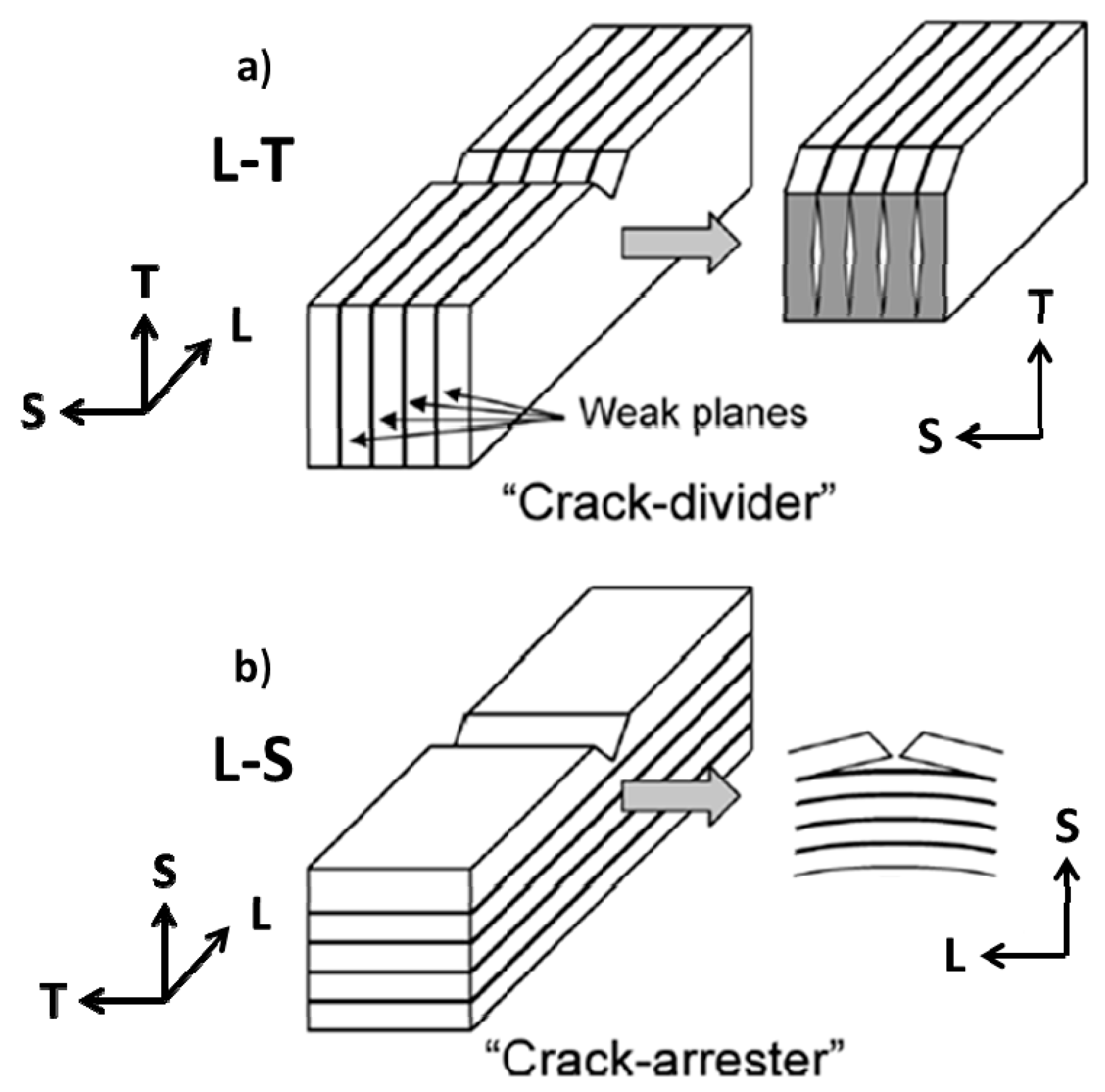
Figure 2.
A schematic illustration of main stress and constraint induced stress in C(T) specimens in (a) two orientations of hot-rolled specimen and (b) three orientations of hot-extruded specimen indicating primary and secondary crack planes.
Figure 2.
A schematic illustration of main stress and constraint induced stress in C(T) specimens in (a) two orientations of hot-rolled specimen and (b) three orientations of hot-extruded specimen indicating primary and secondary crack planes.
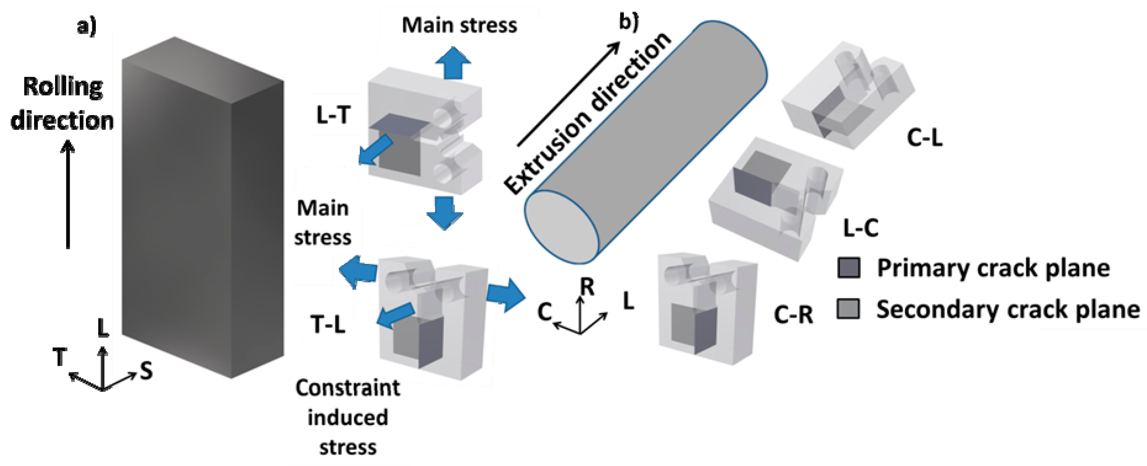
Figure 3.
Backscattered SEM images of OP-S polished surface showing aligned holes (encircled) formed after Ti-enriched particle fall out in ODS-KIT HR in the (a) LS plane and in the (b) TS plane together with the (c) longitudinal plane of ODS-KIT HE showing arranged Ti particle fall out in the longitudinal direction.
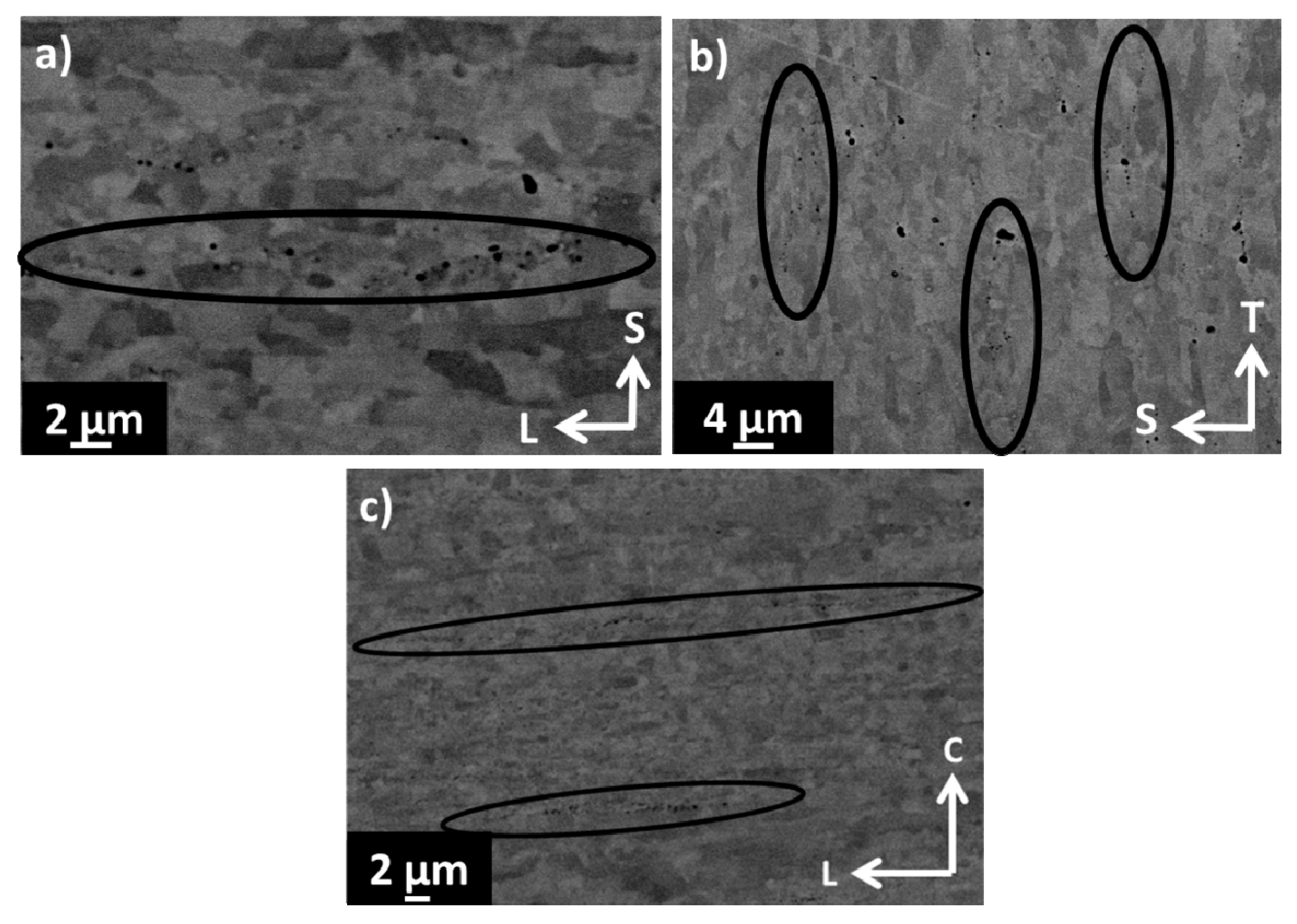
Figure 4.
Inverse pole figure Z maps of ODS-KIT HR in (a) TS (b) LT and (c) LS plane and ODS-KIT HE in (d) transversal plane (T) and (e) longitudinal plane (L) (10° misorientation angle threshold). Indicated GAR values are for coarse grains.
Figure 4.
Inverse pole figure Z maps of ODS-KIT HR in (a) TS (b) LT and (c) LS plane and ODS-KIT HE in (d) transversal plane (T) and (e) longitudinal plane (L) (10° misorientation angle threshold). Indicated GAR values are for coarse grains.

Figure 5.
Inverse pole figures of (a) LT plane in ODS-KIT HR and (b) longitudinal plane (L) in ODS-KIT HE.
Figure 5.
Inverse pole figures of (a) LT plane in ODS-KIT HR and (b) longitudinal plane (L) in ODS-KIT HE.
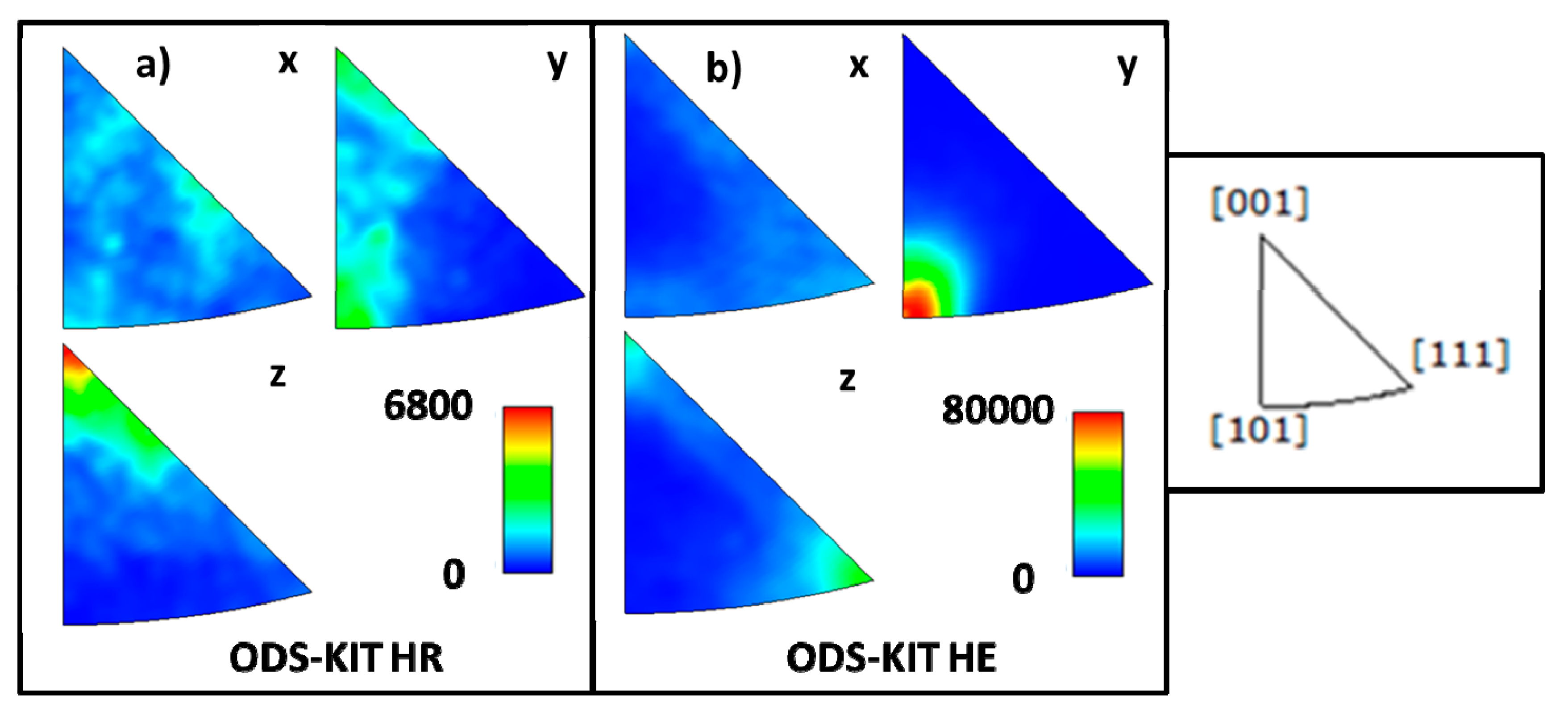
Figure 6.
Comparison of L-T oriented specimen of ODS-KIT HR with L-C oriented specimen of ODS-KIT HE using (a) Fracture toughness versus yield strength curve at various temperatures and (b) Load versus load line displacement at RT along with (c) Load versus load line displacement curve of ODS-KIT HR in all the orientations at RT and (d) Load versus load line displacement curve of ODS-KIT HE in all the orientations at RT.

Figure 7.
Stereo microscope images of (a) ODS-KIT HR and (b) ODS-KIT HE fracture surfaces at different temperatures and in different orientations.
Figure 7.
Stereo microscope images of (a) ODS-KIT HR and (b) ODS-KIT HE fracture surfaces at different temperatures and in different orientations.

Figure 8.
SEM image showing an arrested secondary crack in (a) low magnification and (b) high magnification in the L-C oriented specimen of ODS-KIT HE at RT.
Figure 8.
SEM image showing an arrested secondary crack in (a) low magnification and (b) high magnification in the L-C oriented specimen of ODS-KIT HE at RT.

Figure 9.
Stereo microscope and SEM images of secondary crack fracture surfaces of ODS-KIT HR at (a–c) RT, (d–f) 200 °C and (g–i) 600 °C for the L-T orientation. The notch is on the right of all the images and the primary crack propagates towards the T direction. Secondary cracks initiate at the TS plane and then propagate in the L (depth) and the T (in-plane) directions.
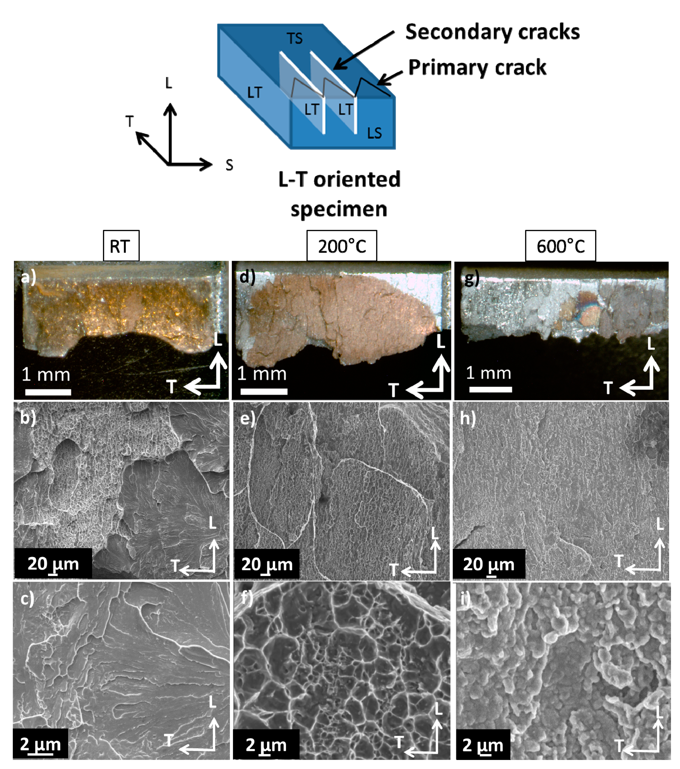
Figure 10.
Misorientation line scans across a secondary crack in an L-T oriented specimen of ODS-KIT HR using EBSD IPF (a) X map, (b) Y map and (c) Z map of the TS plane at RT. (d) Line scan 1 is magnified and (e) the corresponding misorientation versus distance graph is displayed.
Figure 10.
Misorientation line scans across a secondary crack in an L-T oriented specimen of ODS-KIT HR using EBSD IPF (a) X map, (b) Y map and (c) Z map of the TS plane at RT. (d) Line scan 1 is magnified and (e) the corresponding misorientation versus distance graph is displayed.

Figure 11.
Misorientation line scans across a secondary crack in an L-T oriented specimen of ODS-KIT HR using EBSD IPF (a) X map, (b) Y map and (c) Z map of the LS plane at 600 °C. (d) The corresponding misorientation versus distance graph is displayed for line scans 1 and 2.
Figure 11.
Misorientation line scans across a secondary crack in an L-T oriented specimen of ODS-KIT HR using EBSD IPF (a) X map, (b) Y map and (c) Z map of the LS plane at 600 °C. (d) The corresponding misorientation versus distance graph is displayed for line scans 1 and 2.


| Material | Plane | Mean Grain Size (µm) | GAR | Area Fraction (%) |
|---|---|---|---|---|
| HR | TS (0.3–3 µm) | 1 | 2 | 20.4 |
| HR | LT (1.4–10 µm) | 3 | 1.6 | 27.3 |
| HR | LS (0.4–3 µm) | 1.1 | 2 | 17.6 |
| HE | T (0.2–3 µm) | 0.78 | 1.7 | 68.9 |
| HE | L (0.2–3 µm) | 0.9 | 1.7 | 39.4 |
| Material | Plane | Mean Grain Size (µm) | GAR | Area Fraction (%) |
|---|---|---|---|---|
| HR | TS (3–13 µm) | 6 | 4 | 79.6 |
| HR | LT (10–91 µm) | 21 | 3.3 | 72.7 |
| HR | LS (3–16 µm) | 6 | 10 | 82.4 |
| HE | T (3–21 µm) | 4.7 | 2.2 | 31.1 |
| HE | L (3–34 µm) | 7.7 | 10 | 60.6 |
Table 3.
Fracture toughness (JQ) values for ODS-KIT HE and ODS-KIT HR at various temperatures (from [17,18]).
| Temperature °C | HE JQ (L-C) kJ/m2 | HE JQ (C-R) kJ/m2 | HE JQ (C-L) kJ/m2 | HR JQ (L-T) kJ/m2 | HR JQ (T-L) kJ/m2 |
|---|---|---|---|---|---|
| −100 | - | - | - | 49.2 | 45 |
| 22 | 486.27 | 97.26U | 44.07U | 78.2 | 28.4 |
| 100 | - | - | - | 45.6 | 15.8 |
| 200 | 488.52 | 146.17 | 107.54 | 43.4 | 19U |
| 400 | 300.73 | 95.6 | 78.06 | 50.1 | 9.9U |
| 600 | 19.69 | 4.04 | 0.95 | 17.1 | 6.5 |
| 700 | - | - | - | 12.9 | 5.8 |
© 2018 by the authors. Licensee MDPI, Basel, Switzerland. This article is an open access article distributed under the terms and conditions of the Creative Commons Attribution (CC BY) license (http://creativecommons.org/licenses/by/4.0/).
Share and Cite
MDPI and ACS Style
Das, A.; Viehrig, H.-W.; Altstadt, E.; Bergner, F.; Hoffmann, J. Why Do Secondary Cracks Preferentially Form in Hot-Rolled ODS Steels in Comparison with Hot-Extruded ODS Steels? Crystals 2018, 8, 306. https://doi.org/10.3390/cryst8080306
AMA Style
Das A, Viehrig H-W, Altstadt E, Bergner F, Hoffmann J. Why Do Secondary Cracks Preferentially Form in Hot-Rolled ODS Steels in Comparison with Hot-Extruded ODS Steels? Crystals. 2018; 8(8):306. https://doi.org/10.3390/cryst8080306
Chicago/Turabian StyleDas, Aniruddh, Hans-Werner Viehrig, Eberhard Altstadt, Frank Bergner, and Jan Hoffmann. 2018. "Why Do Secondary Cracks Preferentially Form in Hot-Rolled ODS Steels in Comparison with Hot-Extruded ODS Steels?" Crystals 8, no. 8: 306. https://doi.org/10.3390/cryst8080306
Note that from the first issue of 2016, this journal uses article numbers instead of page numbers. See further details here.