
Microstructure and Dielectric Properties of PTFE-Based Composites Filled by Micron/Submicron-Blended CCTO

School of Optical and Electronic Information, Huazhong University of Science and Technology, Wuhan 430074, China
*
Author to whom correspondence should be addressed.
Crystals 2017, 7(5), 126; https://doi.org/10.3390/cryst7050126
Submission received: 12 March 2017
/
Revised: 20 April 2017
/
Accepted: 25 April 2017
/
Published: 30 April 2017
(This article belongs to the Special Issue Crystal Structure of Electroceramics)
Abstract
:This paper investigated a polymer-based composite by homogeneously embedding calcium copper titanate (CaCu3Ti4O12; CCTO) fillers into a polytetrafluoroethylene matrix. We observed the composite filled by CCTO powder at different sizes. The particle size effects of the CCTO filling, including single-size particle filling and co-blending filling, on the microstructure and dielectric properties of the composite were discussed. The dielectric performance of the composite was investigated within the frequency range of 100 Hz to 1 MHz. Results showed that the composite filled by micron/submicron-blended CCTO particles had the highest dielectric constant (εr = 25.6 at 100 Hz) and almost the same dielectric loss (tanδ = 0.1 at 100 Hz) as the composite filled by submicron CCTO particles at the same volume percentage content. We researched the theoretical reason of the high permittivity and low dielectric loss. We proved that it was effective in improving the dielectric property of the polymer-based composite by co-blending filling in this experiment.
1. Introduction
Substrate materials have gained considerable attention because of their roles in the continuous development of the high-technology electronic industry [1]. Traditional polymer materials, such as polytetrafluoroethylene (PTFE) [2,3] and epoxy [4], are flexible and can be produced by a simple process. However, these materials cannot meet the developing trends of miniaturization and integration of electronic systems because of their low dielectric permittivity [5,6,7]. Ceramic/polymer composites, in which particles with high dielectric permittivity are used as fillers and polymers are used as the matrix, combine the merits of ceramics and polymers with high dielectric permittivity and excellent mechanical properties. These composites exhibit potential for various applications [8,9,10,11]. For instance, they are widely used in high charge-storage capacitors and high-speed integrated circuits, as well as other fields [12,13,14]. Materials containing calcium copper titanate (CaCu3Ti4O12; CCTO) also show potential to be applied to embedded devices, etc. Compared with CCTO/polyvinylidene fluoride (PVDF) composites, which have been widely studied, our results show lower losses, which indicate these filled CCTO/PTFE materials can be applied to fields requiring high dielectric constants and low losses, such as substrate materials.
Calcium copper titanate (CaCu3Ti4O12; CCTO) is one of the most remarkable ceramic materials because of its high dielectric permittivity, reaching as high as 104 to 105, its almost non-dependence on frequency up to 10 MHz, and its low thermal coefficient of dielectric permittivity from 100 K to 600 K [15,16]. To develop applications for CCTO, scholars aim to minimize the high dielectric loss [17,18,19]. Simultaneously, attempts have been made to explore the possibility of obtaining high dielectric permittivity composites for potential electronic components by embedding CCTO particles into polymer [20,21,22,23]. Dang [24] utilized in situ polymerization to disperse CCTO powders into a polyimide matrix and obtained a composite film with a dielectric permittivity of 49 when the volume fraction was 40 vol % at 100 Hz. Chi [25] reported that a relatively high dielectric permittivity, low loss, and low conductivity were simultaneously achieved in nano-sized CCTO/PI films. Compared with the micro-sized CCTO/PI film with a 10 vol % concentration of micro-sized CCTO, the dielectric permittivity of the nano-sized CCTO/PI film with a 3 vol % concentration of nano-sized CCTO increased by 16%. Yang [26] investigated the effect of nano- and micro-sized CCTO on the CCTO/PVDF composite. The effective dielectric constant (εr) of the composite containing 40 vol % nano-sized CCTO filler is more than 106 at 102 Hz and room temperature. This value is substantially higher than the dielectric constant of the composite containing micro-sized CCTO, with a εr value of 35.7 (at 40 vol %).
When the single-particle size of the CCTO powder is filled at high amounts, the CCTO particles cannot be totally encased by the PTFE matrix. The particles agglomerate to form voids, which are difficult to be filled by the PTFE matrix, thereby decreasing the dielectric constant of the composite. The volume percentage fraction of the ceramic filler should be less than 40% to reduce the porosity and preserve the mechanical properties. In our experiment, we fabricated a CCTO/PTFE composite film with 30 vol % filler. To solve these limitations, researchers have investigated double-particle-sized hybrids characterized by high density [27]. In this paper, we synthesized the submicro-sized CCTO powder by the oxalate co-precipitation method and the micro-sized CCTO powder by the solid-state reaction method. Both CCTO powders were blended at a proportion of 1:1 and the mixture was filled in the PTFE matrix. The microstructure and dielectric properties of the CCTO/PTFE composite with different particle sizes were investigated and compared. Moreover, the dielectric mechanism of the PTFE/CCTO composite is discussed in detail.
2. Experimental Section
Submicro-sized CCTO precursor powders were obtained through co-precipitation. The metal chlorides (CaCl2, TiCl3, and CuCl2–2H2O) were dissolved in water and added as precipitation agents to ethanol-containing oxalic acid. The precursors were calcined in air at 750 °C, 800 °C, and 850 °C for 10 h to obtain the oxide powders [28]. Micro-sized CCTO powder was synthesized by the solid-state reaction method [29]. Calcium (CaCO3, 99.9%), copper oxide (CuO, 99.9%), and titanium dioxide (TiO2, 99.9%), were purchased from Sigma-Aldrich (Chemical Reagent Co., Ltd., Shanghai, China) and used as raw materials. High-purity metal oxides were weighed based on the stoichiometric ratio and calcined at 950 °C for 10 h to obtain CCTO particles. Both CCTO powders were blended at a proportion of 1:1 and the mixture was ground with a titanate coupling agent to enhance the interface between the matrix and the filler. Emulsion polymerization was employed to disperse the CCTO powder into the PTFE emulsion (Shanghai 3F New Material Co., Ltd., Shanghai, China) with magnetic agitation at 90 °C [30]. The obtained dry mixture was smashed into a powder after heat treatment in a muffle furnace at 270 °C. The powder was pressed to obtain tablet samples approximately 18 mm in diameter and 1 mm in thickness. Cylindrically-shaped samples were prepared for microwave frequency measurements. In addition, samples were calcined at a low temperature of 370 °C to obtain the composite.
The sample structure was examined by X-ray diffraction (XRD; XRD-7000, Shimadzu, Kyoto, Japan) with Cu Kα1 radiation (λ = 0.154056 nm) over the 10°–80° 2θ range. The microstructures of the freshly-fractured cross-section of the PTFE/CCTO composites were examined using a field-emission scanning electron microscope (FESEM, Sirion 200, FEI, Eindhoven, Netherlands), and we used Image-Pro Plus 6.0 to obtain the porosity of three different particle-sized samples by calculating the area of the black part in the SEM micrographs. The thermal analysis system used in this study was TGA-DSC (METTLER TOLEDO, TGA/DSC-1). The dielectric properties of composite were measured using an impedance analyzer (Agilent 4294A, Agilent Technologies, Santa Clara, CA, USA) at room temperature in the frequency range of 100 Hz to 1 MHz. A thin layer of silver was painted on both sides of the tablet samples before measurement.
3. Results and Discussion
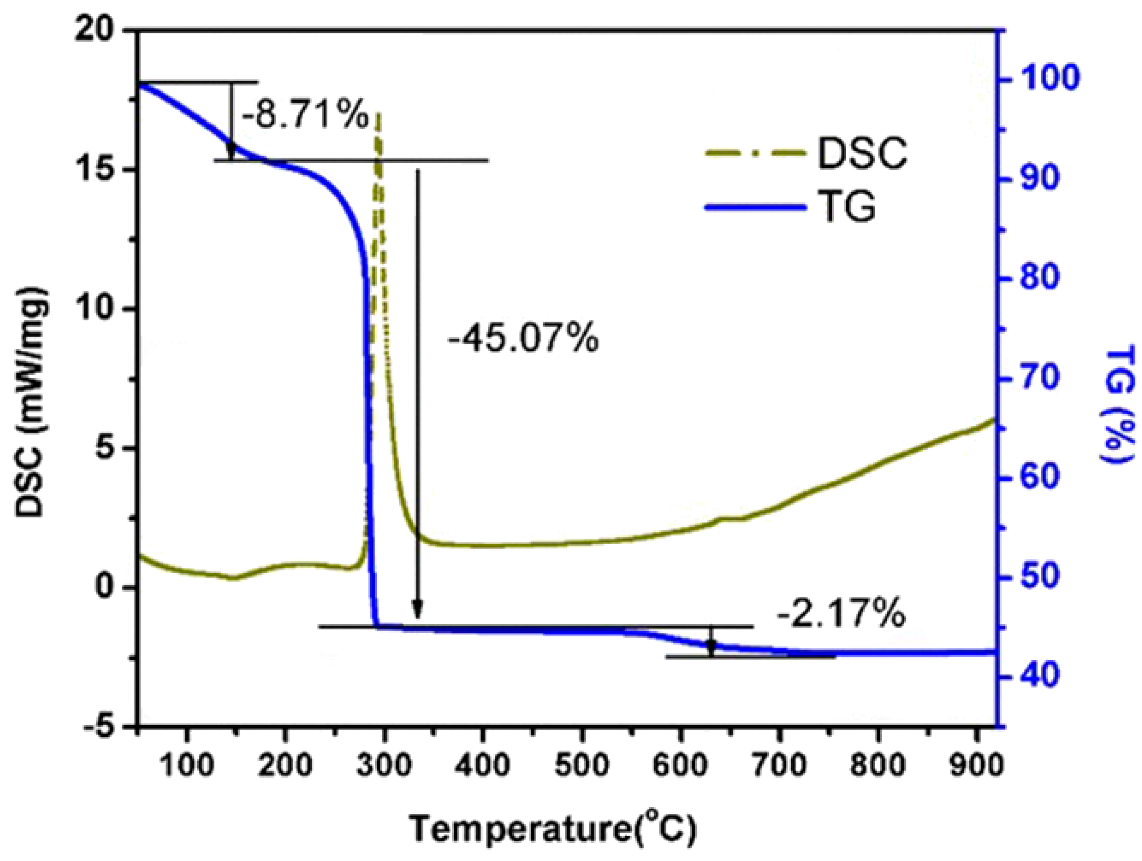
Figure 1 presents the thermal gravimetric analysis (TGA) of the CCTO precursor. The thermal process is mainly divided into three stages. The weightlessness of the CCTO precursor is about 8.71% at the first stage from 50 °C to 200 °C. The corresponding DSC curve appears to be a weak endothermic peak which is attributed to water evaporation. At the second stage, from 200 °C to 300 °C, the weightlessness of the CCTO precursor is about 45.07% and the corresponding DSC curve appears to have a sharp exothermic peak which is attributed to the combustion decomposition of organic matter, such as oxalate and nitrate. At the third stage, from 560 °C to 700 °C, as the weightlessness of the CCTO precursor is about 2.17%, and the corresponding DSC curve appears to have a weak exothermic peak which may correspond to CCTO crystallization. Figure 2 shows the XRD pattern of CCTO powders calcined at 750 °C, 800 °C, and 850 °C. CCTO appears as the major phase, and small amounts of CaTiO3 and CuO are also present in the three samples; however, TiO2 is only present in the sample calcined at 750 °C.
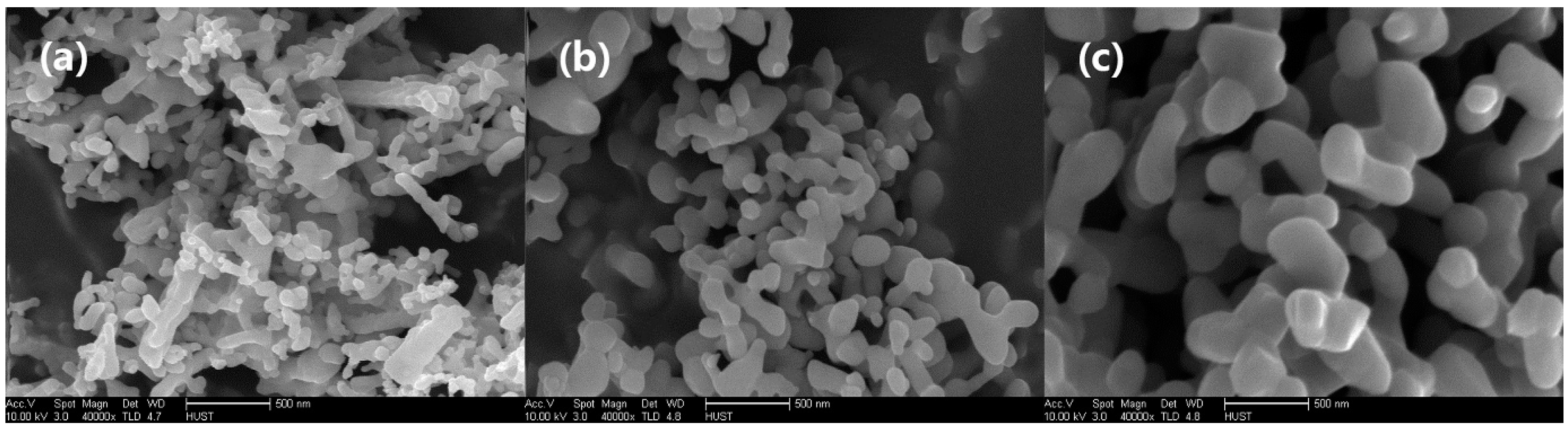
Figure 3 shows the scanning electron microscopy (SEM) images of the CCTO powder calcined at different temperatures: (a) 750 °C, (b) 800 °C, and (c) 850 °C. Some spherical and rod-like particles appear in the CCTO powders calcined at 750 °C. The CCTO powders with sizes of about 100–200 nm are uniform and spherical at the calcination temperature of 800 °C. When the temperature rises to 850 °C, the CCTO particles grow further and their sizes increase to about 300 nm to 500 nm. According to the XRD and SEM results, the synthesis temperature of the submicron CCTO powder was determined to be 800 °C, in order to obtain a smaller and homogeneous submicron grain and reflect the effect of particle size on the dielectric properties of the composites as much as possible.
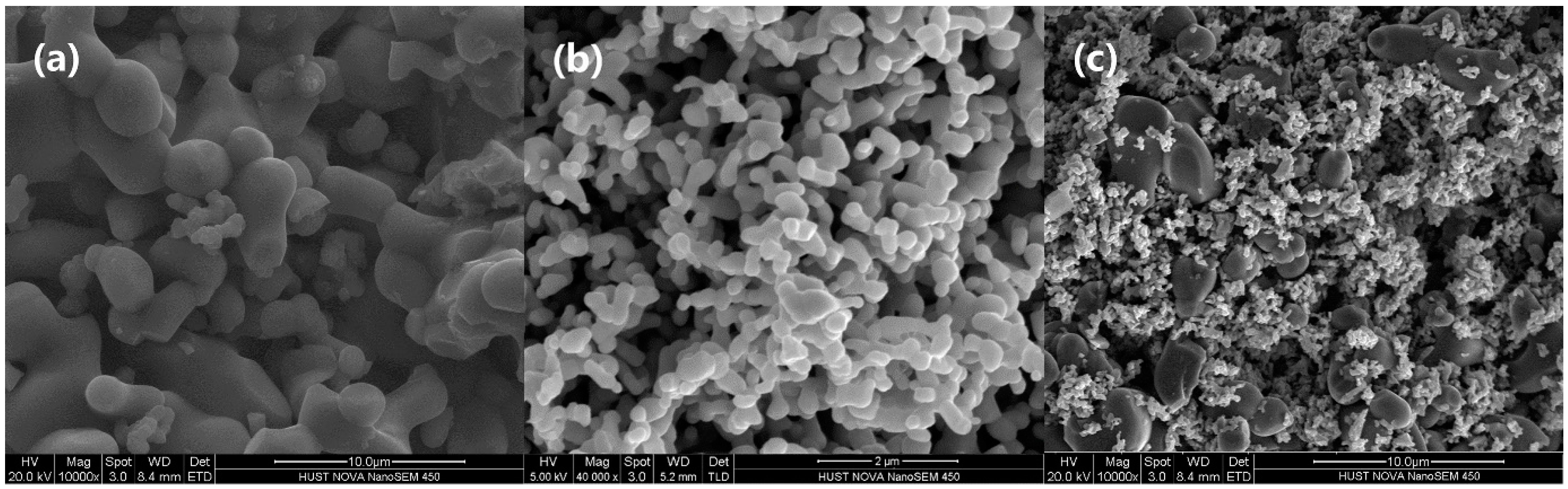
Figure 4 shows SEM micrographs of the CCTO powder at different particle sizes. The particle size of the micron CCTO powder prepared by the solid-state reaction method is not uniform, ranging from 2 μm to 10 μm. CCTO powders prepared by the co-precipitation method appear to have spherical particles with uniform sizes. However, these particles agglomerated to form a cluster with some voids existing in them. In the micron/submicron co-blended CCTO powder, micron-sized particles are uniformly distributed while submicron particles fill in the gaps between the micron-sized particles. As shown in Figure 4, the micron/submicron co-blended CCTO powder has a significantly higher filling density than the other two groups with a single particle size.
Figure 5 shows the SEM micrograph of the PTFE-based composite filled by 30 vol % CCTO powder with different particle sizes. Micron CCTO powders were uniformly coated by the PTFE matrix, while submicron CCTO powders were not completely coated by PTFE because of their agglomeration. Comparing the two kinds of composites, the composite filled by the micron/submicron co-blended CCTO powder showed the highest density because the submicron particles filled the gaps not only among micron-sized CCTO particles, but also between micron-sized CCTO particles and the PTFE matrix to minimize the surface energy of the system. According to our statistics, the porosity of the composites filled with micron, submicron, and micron/submicron co-blending CCTO is, respectively, 19.43%, 13.98%, and 11.05%. Lower porosity leads to higher dielectric permittivity [17,31], as shown in Figure 7. In addition, the surface area-volume ratio of submicron CCTO powder is 88,737 cm2/cm3, much larger than 13,425 cm2/cm3 of micron CCTO powder. The stronger interfacial polarization mostly caused by the large specific surface area also contributes to the high permittivity [21,26].
Figure 6 shows the XRD patterns of the PTFE-based composite filled with 30 vol % CCTO powder at different sizes. All three composite materials have the characteristic peak of CCTO and PTFE. The composite filled by micron CCTO has an obviously higher CCTO peak intensity than the other two groups. This is because the growth of micron CCTO ceramic particles is more complete, with the particles having better crystallinity. In addition, the great specific surface area of submicron CCTO results in diminishment of its peak intensity. Conversely, the effect results in the uniform distribution of micron-sized CCTO particles in the PTFE matrix and less damage of the PTFE chain. Therefore, the PTFE characteristic peak at 2θ = 18.2° is stronger than that of the other two groups. Furthermore, Figure 6 shows that the PTFE characteristic peak in the composite filled by micron and submicron CCTO particles is the weakest and, together with Figure 5, they indicate that the PTFE chain destruction is stronger than that of the other two groups, and the composite materials filled by micron and submicron CCTO particles exhibit the highest density.
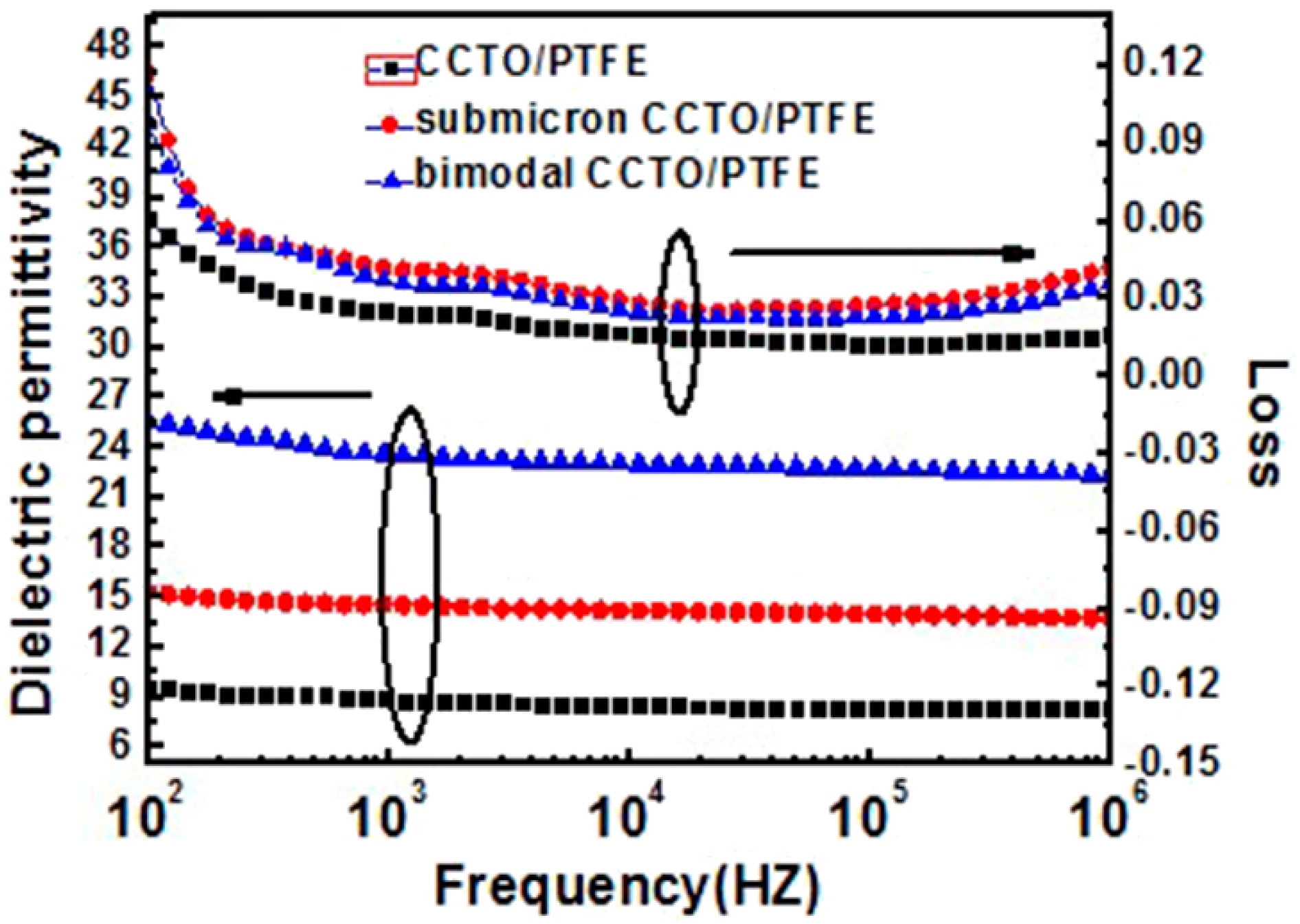
Figure 7 shows the frequency dependence of the dielectric properties of the composites with different CCTO particle sizes. All dielectric constants of the three composites show good frequency stability. Moreover, the composite filled by the double-particle-sized CCTO powder has a higher dielectric constant, which is up to 25.6 at a frequency of 100 Hz, than the other two composites. This is attributed to its stronger interfacial polarization and higher density. The dielectric constant of the composite filled by sub-micron CCTO particles is slightly higher than that of the composite filled by micron CCTO particles because a large number of voids are caused by the agglomeration of submicron CCTO particles. Additionally, the grain size effects contribute to the higher dielectric properties of the composite [32,33]. Figure 7 shows that the dielectric loss of the three composites decreased rapidly with increasing frequency at 100 Hz–1 kHz, but increased when the frequency increased to nearly 106 Hz. The dielectric loss of submicron and co-filled composites change more obviously than the micron-sized composite because of their greater specific surface area and stronger interfacial polarization.
4. Conclusions
In this paper, PTFE was filled by micron, submicron, and micron/submicron-blended CCTO powder at three different sizes. The effects of the filler particle sizes on the microstructure and dielectric properties were discussed. The research results showed that the composite filled by micron/submicron-blended CCTO particles had the highest density and dielectric constant with the same volume percentage content. The dielectric loss of the three composites decreased with an increase in the frequency. The composite filled by micron/submicron CCTO particles had a higher dielectric constant and almost the same dielectric loss as the composite filled by submicron CCTO particles, which may be attributed to the higher density of the former.
Acknowledgments
The authors would like to acknowledge financial support from the National Natural Science Foundation of China through grant No. 61172004 and the Fundamental Research Funds for the Central Universities, No. 201509.
Author Contributions
Chao Xie and Fei Liang conceived and designed the experiments; Chao Xie, Min Ma, and Xizi Chen performed the experiments; and Wenzhong Lu and Yunxiang Jia analyzed the data. All authors participated in the research, analysis, and edition of the manuscript.
Conflicts of Interest
The authors declare no conflict of interest.
References
- Youngs, I.J.; Stevens, G.C.; Voughan, A.S. Trends in dielectrics research: An international review from 1980 to 2004. J. Phys. D Appl. Phys. 2006, 39, 1267. [Google Scholar] [CrossRef]
- Murali, K.P.; Rajesh, S.; Prakash, O.; Kulkarni, A.R.; Ratheesh, R. Comparison of alumina and magnesia filled PTFE composites for microwave substrate applications. Mater. Chem. Phys. 2009, 113, 290. [Google Scholar] [CrossRef]
- Liang, F.; Zhang, L.; Lu, W.Z.; Wan, Q.X.; Fan, G.F. Dielectric performance of polymer-based composites containing core-shell Ag@TiO2 nanoparticle fillers. Appl. Phys. Lett. 2016, 108, 072902. [Google Scholar] [CrossRef]
- Prakash, B.S.; Varma, K.B.R. Dielectric behavior of CCTO/epoxy and Al-CCTO/epoxy composites. Compos. Sci. Technol. 2007, 67, 2363–2368. [Google Scholar] [CrossRef]
- Dang, Z.M.; Yuan, J.K.; Zha, J.W.; Zhou, T.; Li, S.T.; Hu, G.H. Fundamentals, processes and applications of high-permittivity polymer—Matrix composites. Prog. Mater. Sci. 2012, 57, 660. [Google Scholar] [CrossRef]
- Dang, Z.M.; Yuan, J.K.; Yao, S.H.; Liao, R.J. Flexible nanodielectric materials with high permittivity for power energy storage. Adv. Mater. 2013, 25, 6334–6365. [Google Scholar] [CrossRef] [PubMed]
- Sebastian, M.T.; Jantunen, H. Polymer-ceramic composites of 0-3 connectivity for circuits in electronics: A review. Int. J. Appl. Ceram. Technol. 2010, 7, 415–434. [Google Scholar] [CrossRef]
- Subodh, G.; Deepu, V.; Mohanan, P.; Sebastian, M.T. Dielectric response of high permittivity polymer ceramic composite with low loss tangent. Appl. Phys. Lett. 2009, 95, 062903. [Google Scholar] [CrossRef]
- Singh, P.; Borkar, H.; Singh, B.P.; Singh, V.N.; Kumar, A. Ferroelectric polymer-ceramic composite thick films for energy storage applications. AIP Adv. 2014, 4, 087117. [Google Scholar] [CrossRef]
- Pela’iz-Barranco, A. Dielectric relaxation and electrical conductivity in ferroelectric ceramic/polymer composites around the glass transition. Appl. Phys. Lett. 2012, 100, 212903. [Google Scholar] [CrossRef]
- Lee, H.J.; Zhang, S.J.; Meyer, R.J., Jr.; Sherlock, N.P.; Shrout, T.R. Characterization of piezoelectric ceramics and 1-3 composites for high power transducers. Appl. Phys. Lett. 2012, 101, 032902. [Google Scholar] [CrossRef] [PubMed]
- Lin, Y.-H.; Cai, J.; Li, M.; Nan, C.-W.; He, J. Grain boundary behavior in varistor-capacitor TiO2-rich CaCu3Ti4O12 ceramics. J. Appl. Phys. 2008, 103, 74111. [Google Scholar] [CrossRef]
- Li, W.; Schwartz, R.W. Ac conductivity relaxation processes in CaCu3Ti4O12 ceramics: Grain boundary and domain boundary effects. Appl. Phys. Lett. 2006, 89, 242906. [Google Scholar] [CrossRef]
- Amaral, F.; Rubinger, C.P.L.; Henry, F.; Costa, L.C.; Valente, M.A.; Barros-Timmons, A. Dielectric properties of polystyrene-CCTO composite. J. Non-Cryst. Solids 2008, 354, 5321–5322. [Google Scholar] [CrossRef]
- Subramanian, M.A.; Li, D.; Duan, N.; Reisner, B.A.; Sleight, A.W. High dielectric constant in ACu3Ti4O12 and ACu3Ti3FeO12 phases. J. Solid State Chem. 2000, 151, 323–325. [Google Scholar] [CrossRef]
- Homes, C.C.; Vogt, T.; Shapiro, S.M. Optical Response of High-Dielectric-Constant Perovskite-Related Oxide. Science 2001, 293, 673. [Google Scholar] [CrossRef] [PubMed]
- Liu, P.; Lai, Y.M.; Zeng, Y.M.; Wu, S.; Huang, Z.H.; Han, J. Influence of sintering conditions on microstructure and electrical properties of CaCu3Ti4O12 (CCTO) ceramics. J. Alloys Compd. 2015, 650, 59–64. [Google Scholar] [CrossRef]
- De Almeida-Didry, S.; Autret, C.; Lucas, A.; Honstettre, C.; Pacreau, F.; Gervais, F. Leading role of grain boundaries in colossal permittivity of doped and undoped CCTO. J. Eur. Ceram. Soc. 2014, 34, 3649–3654. [Google Scholar] [CrossRef]
- Tang, H.; Zhou, Z.; Bowland, C.C.; Sodano, H.A. Synthesis of calcium copper titanate (CaCu3Ti4O12) nanowires with insulating SiO2 barrier for low loss high dielectric constant nanocomposites. Nano Energy 2015, 17, 302–307. [Google Scholar] [CrossRef]
- Yang, Y.; Zhu, B.P.; Lu, Z.H.; Wang, Z.Y.; Fei, C.L.; Yin, D.; Xiong, R.; Shi, J.; Chi, Q.G.; Lei, Q.Q. Polyimide/nanosized CaCu3Ti4O12 functional hybrid films with high dielectric permittivity. Appl. Phys. Lett. 2013, 102, 042904. [Google Scholar] [CrossRef]
- Yang, Y.; Sun, H.L.; Yin, D.; Lu, Z.H.; Wei, J.H.; Xiong, R.; Shi, J.; Wang, Z.Y.; Liu, Z.Y.; Lei, Q.Q. High performance of polyimide/CaCu3Ti4O12@Ag hybrid films with enhanced dielectric permittivity and low dielectric loss. J. Mater. Chem. A 2015, 3, 4916. [Google Scholar] [CrossRef]
- Gao, L.; Wang, X.; Chen, Y.; Chi, Q.G.; Lei, Q.Q. Ni-coated CaCu3Ti4O12/low density polyethylene composite material with ultra-high dielectric permittivity. AIP Adv. 2015, 5, 087183. [Google Scholar] [CrossRef]
- Arbatti, M.; Shan, X.B.; Cheng, Z.Y. Ceramic–Polymer Composites with High Dielectric Constant. Adv. Mater. 2007, 19, 1369–1372. [Google Scholar] [CrossRef]
- Dang, Z.M.; Zhou, T.; Yao, S.H.; Yuan, J.K.; Zha, J.W.; Song, H.T. Advanced Calcium Copper Titanate polyimide. Adv. Mater. 2009, 21, 2077–2082. [Google Scholar] [CrossRef]
- Chi, Q.G.; Sun, J.; Zhang, C.H.; Liu, G.; Lin, J.Q.; Wang, Y.N.; Wang, X.; Lei, Q.Q. Enhanced dielectric performance of amorphous calcium copper titanate/polyimide hybrid film. J. Mater. Chem. C 2014, 2, 172–177. [Google Scholar] [CrossRef]
- Yang, W.H.; Yu, S.H.; Sun, R.; Du, R.X. Nano- and microsize effect of CCTO fillers on the dielectric behavior of CCTO/PVDF composites. Acta Mater. 2011, 59, 5593–5602. [Google Scholar] [CrossRef]
- Zha, J.W.; Zhu, Y.H.; Li, W.K.; Bai, J.B.; Dang, Z.M. Low dielectric permittivity and high thermal conductivity silicone rubber composites with micro-nano-sized particles. Appl. Phys. Lett. 2012, 101, 062905. [Google Scholar] [CrossRef]
- Marchin, L.; Guillemet-Fritsch, S.; Durand, B. Soft chemistry synthesis of the perovskite CaCu3Ti4O12. Prog. Solid State Chem. 2007, 36, 151–155. [Google Scholar] [CrossRef]
- Ehrhardt, C.; Fettkenhauer, C.; Glenneberg, J.; Münchgesang, W.; Leipner, H.S.; Diestelhorst, M. A solution-based approach to composite dielectric films of surface functionalized CaCu3Ti4O12 and P(VDF-HFP). J. Mater. Chem. A 2014, 2, 2266. [Google Scholar] [CrossRef]
- Barbier, B.; Combettes, C.; Barbiera, B.; Guillemet-Fritschb, S.; Chartierc, T.; Rossignolc, F.; Rumeaud, A.; Lebeyd, T.; Dutardea, E. CaCu3Ti4O12 ceramics from co-precipitation method: Dielectric properties of pellets and thick films. J. Eur. Ceram. Soc. 2009, 29, 731. [Google Scholar] [CrossRef]
- Liu, J.; Gan, D.; Hu, C.; Kiene, M.; Ho, P.S.; Volksen, W.; Miller, R.D. Porosity effect on the dielectric constant and thermomechanical properties of organosilicate films. Appl. Phys. Lett. 2002, 81, 4180–4182. [Google Scholar] [CrossRef]
- Lee, J.; Koh, J. Grain size effects on the dielectric properties of CaCu3Ti4O12 ceramics for supercapacitor applications. Ceram. Int. 2015, 41, 10442–10447. [Google Scholar] [CrossRef]
- Yu, V.; Dang, Z.; Zha, J. Micro-Nanosize Cofilled High Dielectric Permittivity Composites. In Proceedings of the IEEE 9th International Conference on the Properties and Applications of Dielectric Materials, Harbin, China, 19–23 July 2009; pp. 769–772. [Google Scholar]
Figure 1.
TG–DSC curve of the submicron CCTO precursor.

Figure 2.
XRD patterns of submicron CCTO at different calcination temperatures.
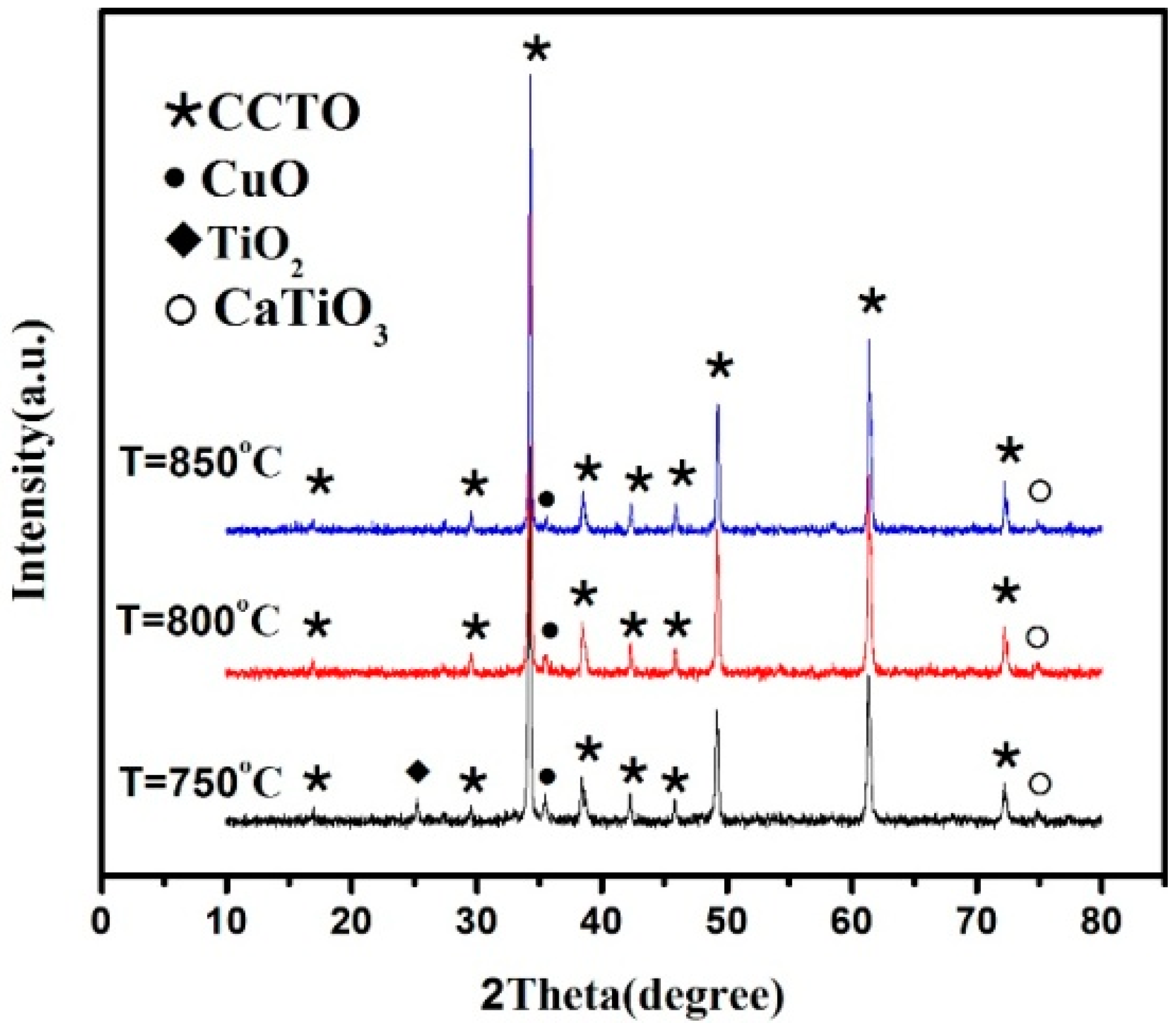
Figure 3.
SEM micrograph of the CCTO powder calcined at different temperatures: (a) 750 °C, (b) 800 °C and (c) 850 °C.
Figure 3.
SEM micrograph of the CCTO powder calcined at different temperatures: (a) 750 °C, (b) 800 °C and (c) 850 °C.

Figure 4.
SEM micrograph of CCTO powder with different particle sizes: (a) micron, (b) submicron, and (c) micron/submicron co-blending.
Figure 4.
SEM micrograph of CCTO powder with different particle sizes: (a) micron, (b) submicron, and (c) micron/submicron co-blending.

Figure 5.
SEM micrograph of the PTFE-based composite filled by different CCTO particle sizes: (a) micron CCTO filling; (b) submicron CCTO filling; and (c) micron/submicron co-blending CCTO filling.
Figure 5.
SEM micrograph of the PTFE-based composite filled by different CCTO particle sizes: (a) micron CCTO filling; (b) submicron CCTO filling; and (c) micron/submicron co-blending CCTO filling.
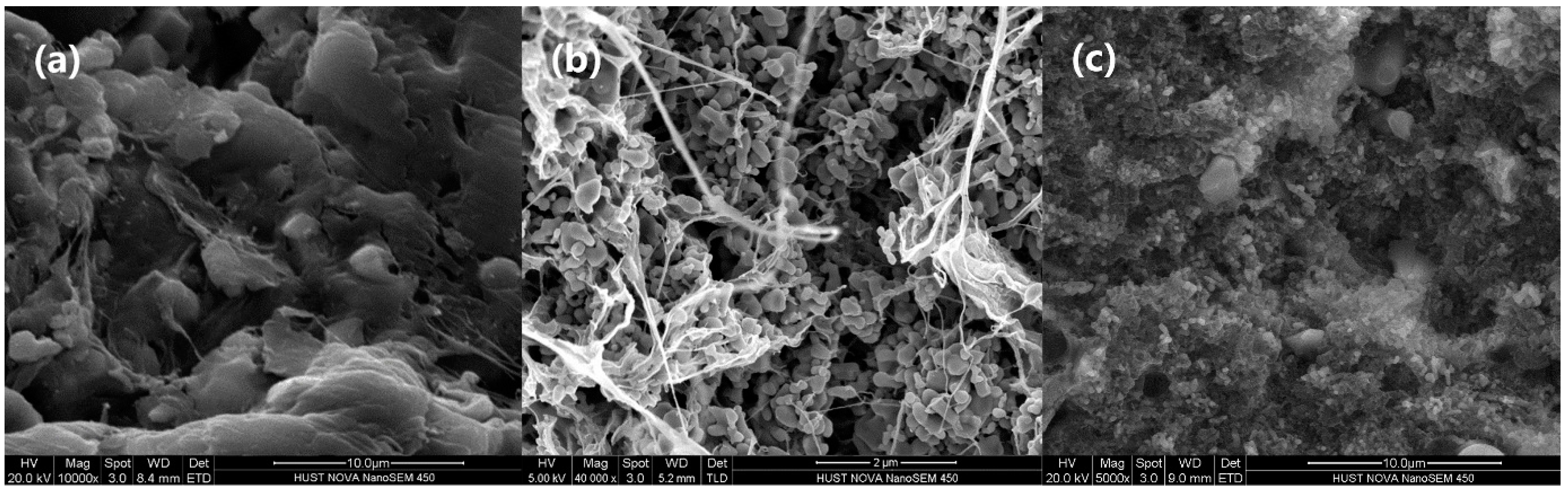
Figure 6.
XRD patterns of the PTFE-based composite filled by different CCTO particle sizes: (a) micron CCTO filling; (b) submicron CCTO filling; and (c) micron/submicron-blended CCTO filling.
Figure 6.
XRD patterns of the PTFE-based composite filled by different CCTO particle sizes: (a) micron CCTO filling; (b) submicron CCTO filling; and (c) micron/submicron-blended CCTO filling.
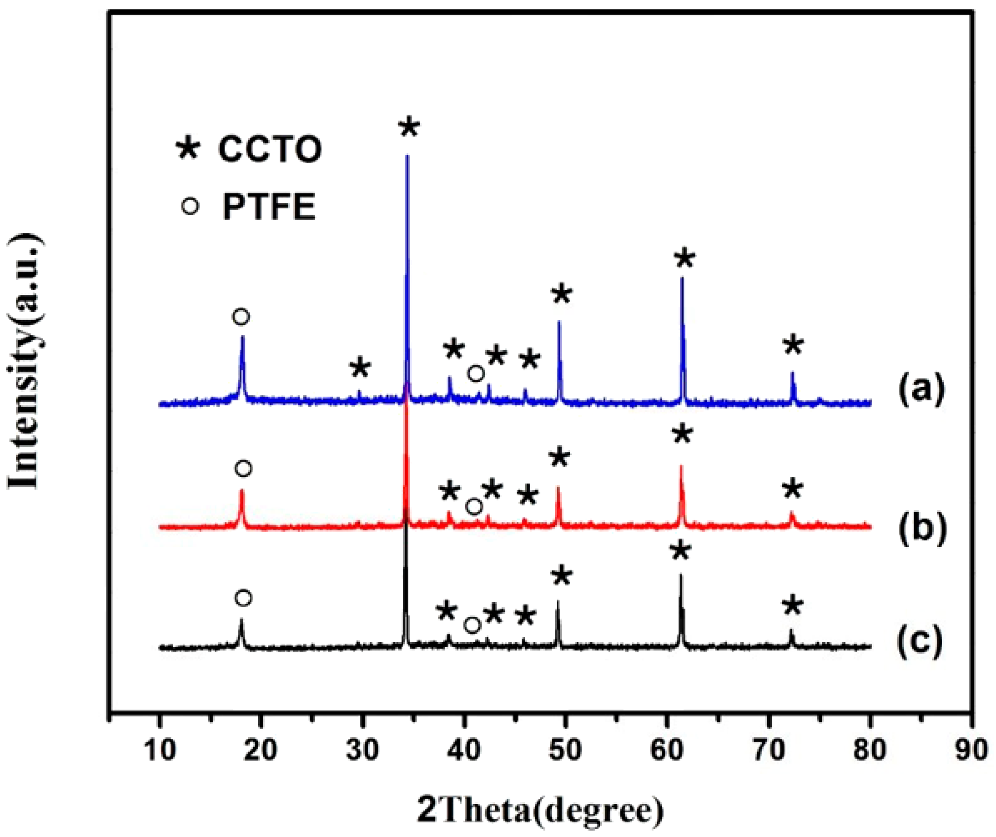
Figure 7.
Frequency dependence of the dielectric properties of the composites with various CCTO particles: (a) the relative permittivity and (b) dielectric loss.
Figure 7.
Frequency dependence of the dielectric properties of the composites with various CCTO particles: (a) the relative permittivity and (b) dielectric loss.
© 2017 by the authors. Licensee MDPI, Basel, Switzerland. This article is an open access article distributed under the terms and conditions of the Creative Commons Attribution (CC BY) license (http://creativecommons.org/licenses/by/4.0/).
Share and Cite
MDPI and ACS Style
Xie, C.; Liang, F.; Ma, M.; Chen, X.; Lu, W.; Jia, Y. Microstructure and Dielectric Properties of PTFE-Based Composites Filled by Micron/Submicron-Blended CCTO. Crystals 2017, 7, 126. https://doi.org/10.3390/cryst7050126
AMA Style
Xie C, Liang F, Ma M, Chen X, Lu W, Jia Y. Microstructure and Dielectric Properties of PTFE-Based Composites Filled by Micron/Submicron-Blended CCTO. Crystals. 2017; 7(5):126. https://doi.org/10.3390/cryst7050126
Chicago/Turabian StyleXie, Chao, Fei Liang, Min Ma, Xizi Chen, Wenzhong Lu, and Yunxiang Jia. 2017. "Microstructure and Dielectric Properties of PTFE-Based Composites Filled by Micron/Submicron-Blended CCTO" Crystals 7, no. 5: 126. https://doi.org/10.3390/cryst7050126
Note that from the first issue of 2016, this journal uses article numbers instead of page numbers. See further details here.