Article

Dopant Concentration Induced Optical Changes in Ca,Eu-α-Sialon

by
Daniel Michalik
1,*,
Tomasz Pawlik
1,
Benedykt Kukliński
2,
Agata Lazarowska
2,
Tadeusz Leśniewski
2,
Justyna Barzowska
2,
Sebastian Mahlik
2,
Marek Grinberg
2,
Barbara Adamczyk
1,
Mateusz Pławecki
3 and
Małgorzata Sopicka-Lizer
1
1
Department of Material Science and Metallurgy, Silesian University of Technology, 40-019 Katowice, Poland
2
Institute of Experimental Physics, Faculty of Mathematics, Physics and Informatics, University of Gdańsk, 80-308 Gdańsk, Poland
3
Institute of Materials Science, University of Silesia, 41-500 Chorzów, Poland
*
Author to whom correspondence should be addressed.
Crystals 2017, 7(11), 342; https://doi.org/10.3390/cryst7110342
Submission received: 17 August 2017 / Revised: 1 November 2017 / Accepted: 3 November 2017 / Published: 8 November 2017

Abstract

:
The phosphor powders of Ca(m/2)−xEuxSi12−(m+n)Alm+nOnN16−n (m = 1.6, n = 0.8, x in the range of 0–0.08) were synthesized by means of a solid state reaction in flowing nitrogen in a carbon resistant furnace and the influence of Eu concentration on the crystal structure and photoluminescent properties was thoroughly studied. The optical properties of selected α-sialon:Eu2+ samples at temperatures in the range of 10 to 500 K and pressures up to 240 kbar are presented. The crystal lattice parameters were affected by doping with europium and some increase of the unit cell volume was observed up to 6 mol % of Eu. The higher concentration of europium led to subtle changes in the overall structure of the produced sialon phosphors. It was shown that the chemical composition of Ca, Eu-α-sialon phosphor was slightly different from the designed one and the phosphor powders were contaminated by AlN. The phosphor particle surface showed significant europium and oxygen enrichment with Eu3+ but below the thin surface layer Eu2+ was dominant and higher nitrogen content was observed. After examination of absorption, excitation, and emission spectra it was found that the emission peak position shifted toward longer wavelengths with rising Eu2+ concentration from 565 nm (0.1 mol % Eu2+) to 585 nm (10 mol % Eu2+). The quantum yield of the phosphors reached the maximum at a rather low concentration of 4 mol % of Eu. Excitation spectra depend on the monitored wavelength which is typical for multisite Eu2+. The existence of many Eu2+ sites in the sample was supported by the dependence of the decay time on the monitored wavelength.

1. Introduction

The application of white light emitting diodes (LEDs) in general lighting and in display devices is an active issue in todays energy saving world. In this technology phosphors play a key role since they down-convert the blue and near ultraviolet light from p-n chip to adjust the complex LED white light.
Currently, one of the most commonly used phosphor materials for the white light emitting diode (WLED) is cerium-doped yttrium aluminum garnet Y3Al5O12:Ce3+. This compound is characterized by very high efficiency of conversion of blue light, which emits p-n chip, into the white light of the LED but the color rendering ability of Y3Al5O12 Ce3+ is unfavorable to the human eyes because of the lack of a red component in its spectrum [1]. Novel, competitive to Y3Al5O12:Ce3+ phosphors multinary nitride-aluminosilicates and nitride-oxo-alumino-silicates have been found to be attractive host lattices for Eu2+ and Ce3+ activators due to their rigid lattice with highly covalent network and excellent thermal stability [1,2,3,4,5,6,7,8,9,10,11,12,13]. The luminescence of Eu2+ is related to the parity allowed 4f65d1→4f7 transitions and consists of a broad band whose maximum varies from UV to red, depending on the host structure and crystal composition. A relatively long wavelength of the Eu2+ emission in nitride based phosphors is observed and attributed to the high covalence of the Si-N lattice bonds and the large crystal field splitting of the 4f65d1 electronic configuration of the Eu2+ coordinated by nitrogen anions. These properties together with strong absorption of light in the range from ultraviolet to blue together with high thermal resistance and chemical stability enables them to be used as excellent phosphors in white LED systems [1,7].
From early nitride phosphor research Ca-α-sialon with the formula of Ca(m/2)−xEuxSi12−(m+n)Alm+nOnN16−n m = 1.6, n = 0.8, has been extensively explored because of its excellent luminescent properties as well as chemical and thermal stability [6,7,14,15,16,17,18]. The framework of M-α-sialon (M = Li, Mg, Ca, Y, Sr, RE) is isostructural with α-Si3N4 and is built up by corner-sharing [(Si, Al) (ON)]4 tetrahedra [19,20]. The cross-substitution of (m+n) Si-N by (n) Al-O and/or (m) Al-N could result in a necessary charge balance but it is compensated for by the inclusion of the relevant metal ion (M). There are two closed interstitials available per unit cell and the M cation is coordinated by seven (N, O) anions at three different M-(N, O) distances [21]. One of them is much shorter than the other six and consequently two out of seven anionic positions are preferentially occupied by the smaller oxygen anion [6]. Such configuration prefers smaller stabilizing cations (Li, Mg, Ca, Y, Yb-Sm) but the crystal lattice expansion induced stresses could be overcome by: (i) a combination of a smaller and larger stabilizing cation (e.g., Ca2+ + Eu2+) [7], (ii) decreasing the oxygen content in aluminum-free α-Si3N4:RE (RE = Eu2+, Ce3+, Tb3+) [22] or parameters (temperature and pressure), (iii) simultaneous substitution of Al3+ and Ca2+ for Si4+ in oxygen-free Ca, Eu-α-sialon [23] with the application of relevant changes in the process.
It has been shown that such large cations as Eu2+ or Sr2+ could be solely incorporated into the α-sialon crystal lattice and both, single-phase Eu-α-sialon [24] and Sr-α-sialon:Eu2+ powders [25] have been produced and characterized. This type of crystal lattice with the excellent capability for solid solution formation gives an opportunity for tailoring the luminescent properties of the phosphor by altering the M cation in the M-α-sialon and/or by varying the oxygen/nitrogen ratio in the local environment of Eu2+ activator. The latter effect determines the actual nearest neighborhood of the Eu2+ that can influence the partial pressure of oxygen during synthesis and the resultant deviation from the designed composition.
Manufacturing of M-α-sialon ceramics was thoroughly studied in the previous century [26,27,28,29] and it has been agreed that the formation of this material involves, first, the development of transient liquid phase from oxides and AlN followed by a complex solution-diffusion-reprecipitation process with a preferential dissolution of small grains and a reprecipitation on larger ones. The covalent nature of the atomic bonds in this lattice limits the atoms diffusion besides thermodynamically governing preferential precipitation of M cations during crystallization [30,31]. In the multi-cation M-α-sialon system the selectivity of cation precipitation with preferential crystallization of the small ones has been already observed [31,32] and can lead to the formation of Eu-enriched grain boundaries [7] or particle surfaces [30]. There are no discussions in the literature in the cases if all europium cations were to be incorporated into the sialon crystal lattice or if they could enter the oxide-rich Ca-Si-Al glass phase. Moreover, the detailed studies performed on the comparison between the nominal and the measured chemical composition of Ca,Eu-α-sialon have demonstrated significant, nearly doubled, growth of the oxygen/nitrogen ratio with some deficiency of silicon [33] aside from the tough process parameters applied: gas-pressure synthesis at 1700 °C for 8 h at 1 MPa nitrogen pressure. On the other hand, careful control of the oxygen presence in the initial materials [34,35] and during the process in a reducing atmosphere [36,37] leads to low oxygen content, below 0.7 wt %, and a red-shifted emission wavelength peaking at 593 nm [36] or 595 nm [37] was observed.
Significant effort in research on europium-doped α-sialon-based phosphors has been lately undertaken in order to determine the optimum dopant concentration, its doping site, and three-dimensional distribution. A basic understanding of the reaction pathways of Eu2+-doped α-sialon is ultimately important for controlling its photoluminescent properties. It has been generally accepted that the broad excitation bands located at about 300 nm and in the range of 400–475 nm are ascribed to the electronic transition between the valence and conduction bands of the host lattice and to the excitation of Eu2+, respectively [36]. The emission bands peaking in the range of 560 to 595 nm are assigned to the 5d-4f transition in Eu2+ ions; the red shift of the emission wavelength occurs at increasing nitrogen concentration [34,35,36,37] and a growing amount of Eu.
In this paper extensive investigations of Ca(0.8−x)EuxSi9.6Al2.4O0.8N15.2 (α-sialon:Eu2+) obtained via a pressureless method with respect to the concentration of Eu2+ in the low range 0 < x < 0.08 is presented. The final phosphor powder was contaminated by a negligible amount of AlN but optimization of the manufacturing process was not a goal of this research. It is discussed in detail how Eu2+ concentration affects the emission spectrum and quantum efficiency of the phosphor. We obtained results indicating that many Eu2+ centers are present in all α-sialon samples leading to concentration dependent effects such as reabsorption and energy transfer. The optical properties of selected α-sialon:Eu2+ samples with respect to temperatures in the range of 10 to 500 K and pressures up to 240 kbar are presented. It is well known [18,25,38,39,40,41,42,43] that by changing the composition of α-sialon (which means changing the degree of substitution of Si-N by Al-O bonds and thus changing the environment around the Eu2+ ions) it is possible to tune, in a certain range, the luminescence properties of Eu2+ doped α-sialon phosphors. The main effect of high pressure is compression of the crystal, i.e., a decrease in its volume and as a consequence a decrease in interatomic distances. The results obtained under high pressure are equivalent to the results that could be obtained via synthesis of materials with similar structure but with different interatomic distances. Therefore one of the purposes of this research was to investigate the changes of luminescence properties with respect to bond lengths changed by hydrostatic pressure instead of by varying the chemical composition.

2. Experimental

Commercially available α-Si3N4 (UBE, SN-E10, >98%), Eu2O3 (Treibacher, 99,99 %), CaCO3 (POCH, >99%), AlN (HC Starck, 98%) and η-Al2O3 (Sasol, 99.96%) were used as starting powders. Starting batch with a nominal composition of Ca(0.8−x)EuxSi9.6Al2.4O0.8N15.2 (x in the range of 0–0.08) was ground in an agate mortar with acetone to form a homogeneous mixture. Detailed values of Eu substitution for Ca (x = 0; 0.0008; 0.016; 0.032; 0.048; 0.064; 0.08) were expressed as an optical activator concentration as 0; 0.1; 2; 4; 6; 8; 10 (mol %). The actual initial batch was contaminated by the excess oxygen since europium was incorporated in the form of Eu2O3 and both nitrides were not oxygen-free. Powders were then placed in an alumina crucible and heated with the rate of 10 °C/min and annealed for 2 h at 1650 °C in a graphite resistance furnace (Thermal Technology, Santa Rosa, CA, USA) in an atmosphere of flowing nitrogen (99.999%).
All measurements of the phosphors were carried out on the finely ground powder. The phase composition was analyzed by X-ray diffraction (XRD) using a PANALYTICAL Empyrean diffractometer (PANalytical B.V., Eindhoven, The Netherlands) equipped with linear detector PIXCel 1D and Johansson monochromator. Data collection was performed over a 2θ range of 10–80° with 0.01°/step and a counting time of 0.008°/s using Ni-filtered Cu Kα radiation. The crystal structure was refined by the Rietvel method using HighScorePlus system (PANalytical B.V., Almelo, The Netherlands) with the employment of ICDD-98-020-1683 standard, Rietveld fit (phase fit), Pseudo Voight (phase profile), Caglioti (FWHM) functions and Size Analysis. The powders’ morphology was studied in a scanning electron microscope (SEM) HITACHI S-3400N (Hitachi High-Technologies Corporation, Tokyo, Japan) which registered backscattered electrons image (BSE). Chemical composition of powdered specimen was carried out with the SEM equipped with an Energy Dispersive Spectrometer (EDS) system. EDS analysis was performed in the several micro-areas under various magnification with 15 kV excitement. Only the metals’ concentration was measured and then it was expressed as an average mol % of a total cation amount. Standard deviation for 10 measurements of each cation concentration was calculated and appropriate discussion on the results probability is provided. Additionally, X-ray photoelectron spectroscopy (Physical Electronics, Inc., Chanhassen, MN, USA) with a Physical Electronics PHI 5700/660 spectrometer, using monochromatized aluminum Kα radiation (hν = 1253.6 eV), at vacuum of 10−9 Torr on a specimen with x = 0.048 (Eu = 5 mol %) was applied. For high resolution spectra, the hemispherical analyzer pass energy was maintained at 11.3 eV. Measurements were performed using a 1 eV/step and 45 min acquisition time (binding energies ranging from 0 to 1400 eV) for survey scans and 0.1 eV/step and 60 min acquisition time for the high resolution scans. Then the sample was etched in Ar ions for 1, 2, and 5 min and high resolution scans were performed in the range of binding energies 1120–1180 eV typical for Eu3+ and Eu2+ 3d3/2 core levels. The analyzed sample area was set to 4 mm2. Calculations and deconvolution of lines were performed using the Multipak programme (ULVAC-PHI, Inc., Kanagawa, Japan). In order to calculate atomic concentrations, the core levels O 1s, C 1s, N 1s, Al 2p, Si 2p, Ca 2p, Eu 3d spectra were measured. Shirley background and symmetric mixed Gaussian-Lorentzian profiles were used to fit the experimental photoelectron peaks [44,45].
Binding energy values were calibrated against the hydrocarbon C 1s line (eV), present because of contamination from ambient air or transport conditions [46,47,48]. Photoluminescence excitation and photoluminescence spectra were acquired using a FluoroMax-4P TCSPC spectrofluorometer produced by Horiba (Horiba Scientific, Kyoto, Japan), containing Czerny-Turner monochromators for excitation and emission. An excitation source in this system was a 150-W ozone-free Xenon lamp. Fluorescence intensity was measured using a R928 Side-on photomultiplier. Luminescence excitation spectra under high pressures were acquired using a system consisting of a 150 W Xe lamp, two SPM2 monochromators (Carl Zeiss, Jena, Germany), and two R928 photomultipliers (Hamamatsu Photonics, Hamamatsu, Japan), the first for the luminescence and the second for reference signal detection. Steady state luminescence spectra were excited with the He-Cd laser with wavelength of 442 nm or 325 nm and DPSS laser with wavelength of 405 nm. Spectra were acquired with an Shamrock SR-750-D1 spectrometer (Andor Technology, Belfast, United Kingdom) equipped with a DU420A-OE type CCD camera.
To follow the luminescence kinetics, we used a system consisting of a PL 2143 A/SS laser and a PG 401/SH parametric optical generator (Ekspla, Vilnius, Lithuania). This system can generate 30 ps laser pulses, with a frequency of 10 Hz with wavelengths ranging from 220 to 2200 nm. The emission signal was analyzed by a Bruker Optics 2501S spectrometer (Bruker Corporation, Billerica, MA, USA) and a Hamamatsu Streak Camera model C4334-01 (Hamamatsu Photonics, Hamamatsu, Japan) with a final spectral resolution of 0.47 nm. Luminescence decays were obtained by the integration of streak camera images over the wavelength intervals. The absolute photoluminescence quantum yield was determined by QY C11347 (Hamamatsu, Photonics Hamamatsu, Japan).
High hydrostatic pressure was applied in a Merrill Bassett diamond anvil cell (DAC). Polydimethylsiloxane oil was used as the pressure-transmitting medium, and the pressure was measured by the shift of the luminescence lines of ruby.

3. Results

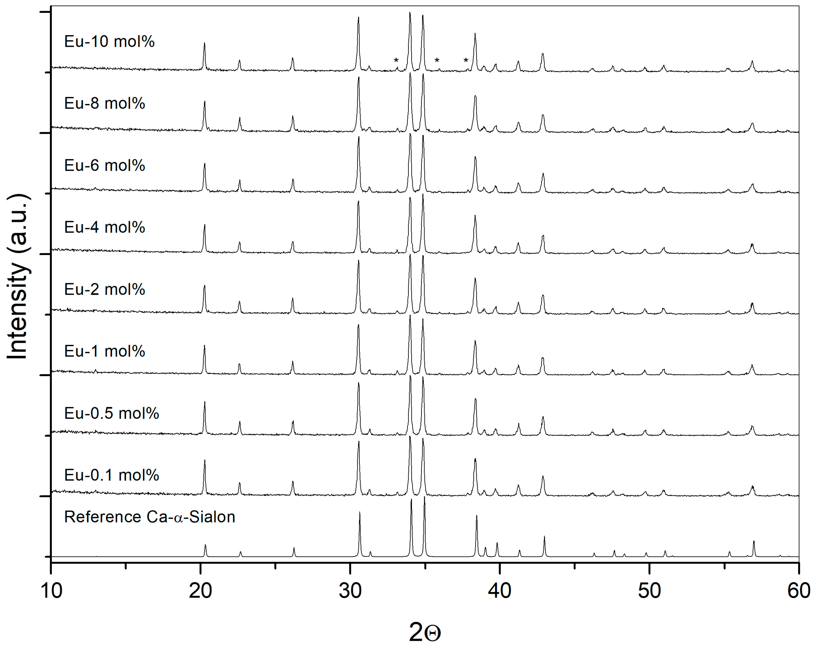
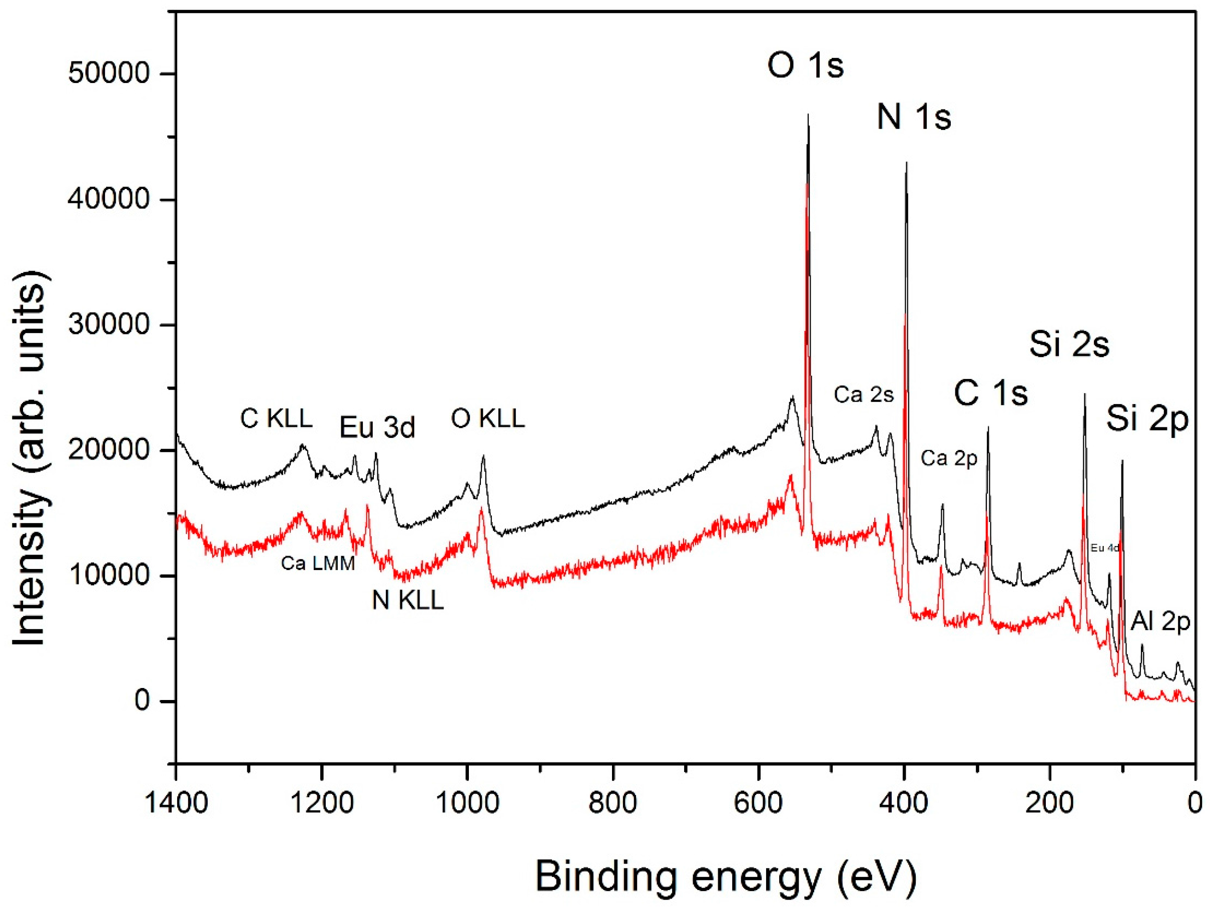
3.1. Physico-Chemical Characterization

The obtained Ca(0.8−x)EuxSi9.6Al2.4O0.8N15.2 (0 < x < 0.08) series samples are all indexed by the Ca-α-sialon phase (ICDD-98-020-1683) but all were contaminated by an amount of AlN, increasing in samples with Eu concentration over 4 mol % (Figure 1, Table 1). AlN contamination in Ca-α-sialon occurs very often if a pressureless technique of manufacturing is used, i.e., flowing nitrogen/hydrogen [23,35,43]. We were able to produce mono-phase Ca,Eu-α-sialon with the aid of the relevant fluxes and various initial compositions [49]. However, from our experience in manufacturing various sialons we know that a slight change in the initial composition usually leads to various chemical compositions of the resultant sialon powder. α- and β-sialons easily form as solid solutions with the concurrent and equivalent substitution of oxygen for nitrogen thus the actual chemical composition of the given sialon is sensitive to the local concentration of elements and partial pressure of both gases. In our study we changed the chemical composition by replacement of Ca atoms by Eu atoms. It was performed by decreasing the amount of CaCO3 and increasing the amount of Eu2O3. Thus we changed the partial pressure of the reactive gases via various amounts of evolving CO gas and excess of oxygen in Eu2O3 since it must be reduced to EuO. Therefore, we decided to keep a thermodynamic/kinetic equilibrium in the given process and to have good reproducibility of the process instead of optimization of the final composition.
All observed peaks satisfy the reflection condition, with the relevant values below of χ2 = 3.06; Rp = 8.4%; Rwp = 11.5%. The low fitting results are related to the variation in relative peak intensities compared to that of the undoped reference Ca-α-sialon. The crystallite size of Ca,Eu-α-sialon was in the narrow range of 59–74 nm and there was no clear dependence on the Eu content; the observed deviation could be rather related to the question of the process reproducibility. On the other hand, the substitution of Ca for Eu does affect the lattice parameters: both, the unit cell dimensions and the volume continuously increase with a growing amount of Eu up to 6 mol %. This effect could be expected since the ionic radius of Eu2+ (1.2 Å) is larger than that of Ca2+ in 7-fold coordination (1.06 Å) [50]. However, previous works indicated that the size of M(II) in α-sialon solid solution does not affect the lattice parameters since the radius of the cage in the parent α-Si3N4 crystal structure (~2.8 Å) is large enough to accommodate optical activator [22]. The unexpected reduction of the unit cell volume after introducing more than 6 mol % of Eu could be related to formation of Si4+ vacancies (higher amount of AlN) or to the shift of α-sialon chemical composition into the nitrogen rich corner. Previous studies on the effect of an Eu amount on Ca-α-sialon:Eu crystal structure show diverse results: increase of lattice parameters [36], no changes reported [34] or maximal values were found for the given Eu amount [43]. The explanation for such a scatter of results is, in our opinion, the various design of Ca,Eu-α-sialon m and n solid solution parameters for charge balance and the actual chemical composition of the resultant sialon phosphor.
The element data in Table 2 from EDS measurements are semi-quantitative as, amongst other factors, the sample surface is not flat, the particles are irregularly shaped, and the relative contribution from the AlN side compound in the sialon particle analysis cannot be assessed. The data can therefore only be used to assess inter-element relationships and a general shift of the measured composition in comparison to a nominal one. The chemical composition of the resultant phosphors, as measured by EDS (Table 2) shows a good correspondence between designed and measured values of the Si concentration within the range of error. On the other hand, the accuracy of the Eu capacity measurements is only on the level of its presence assessment because of the very low concentration in the phosphor powder. Standard deviation of calcium and aluminum amount is rather low and has been estimated to be in a range of +(5–12)% and −(5–8)% respectively. The last column in Table 2, however, shows the ratio of the Ca/Al concentration to be constantly over a designed one. A higher ratio of Ca:Al detected in the microareas/α-sialon grains corresponds to slightly various chemical composition of the obtained sialon phosphor powder with a shift in the direction of a higher m/2(m + n) value indicating higher than designed nitrogen content. AlN phase as measured by XRD was not incorporated into α-sialon solid solution and could be non-homogeneously distributed among sialon grains/particles. The observed deviation from the designed solid solution composition is related rather to the applied technique of phosphor manufacturing than to the Eu concentration. The effect of AlN presence was usually observed if sialon was synthesized under atmospheric pressure [35] and could be suppressed if a AlN-deficient raw materials mixture was applied [40].
XPS analysis of Eu-4 mol % sialon powder performed at the surface of 4 mm2 and at a depth of few nanometers (Table 2) showed a slightly different ratio between the main elements: the Al amount was higher than the designed one while Si was below the expected value. Moreover, the sample was significantly oxidized and some carbon quantitiy was detectable (Figure 2). However, etching the specimen with argon ions for 1 or 2 min led to a noticeable enrichment of nitrogen and silicon. The depth of etching was unknown, but the result clearly shows the oxidized surface of phosphor particles and it evidences Si losses from the particle surface. The present results show that some SiO(g) losses occurred on the particle surface and a higher quantitiy of surface Al shows preferential AlN location. These changes point to the alteration of the surface chemical composition in comparison to the interior of phosphor particles. It is also possible that the surface oxidized film is of M-Si-Al-O-N amorphous nature with higher ability for Eu3+/Eu2+ accommodation.
According to references the two peaks at 1134.7 and 1124.4 eV in the XPS spectrum can be attributed to Eu3+ and Eu2+ 3d5/2 core levels, respectively [48,51,52] while the other two peaks at 1164.8 and 1154.4 eV, can be attributed to Eu3+ and Eu2+ 3d3/2 core levels [48,51,52]. Experimental peak positions for Eu3+ 1134.7, 1164.8 and Eu2+ 1124.4 eV, 1154.4 eV are a good match for peaks from references 1134.3 and 1165.2 with 1124.1 eV and 1153.9 eV, respectively [48]. The XPS analysis suggests that the particle surface is significantly enriched in europium and it is present in both the Eu2+ and Eu3+ oxidation states.
The calcium amount is close to the designed one and does not change after etching, contrary to the Eu concentration. Obviously, the particle surface is enriched in the Eu3+ content (2/3 of the measured value) but under the thin surface layer of the powder particle, the Eu2+ content significantly dominates (Figure 3). We showed for the first time that the chemical composition of the surface layer of the phosphor particles deviates from the interior thus the luminescent properties of these materials would be altered by the fraction of the surface, namely the specific surface area.

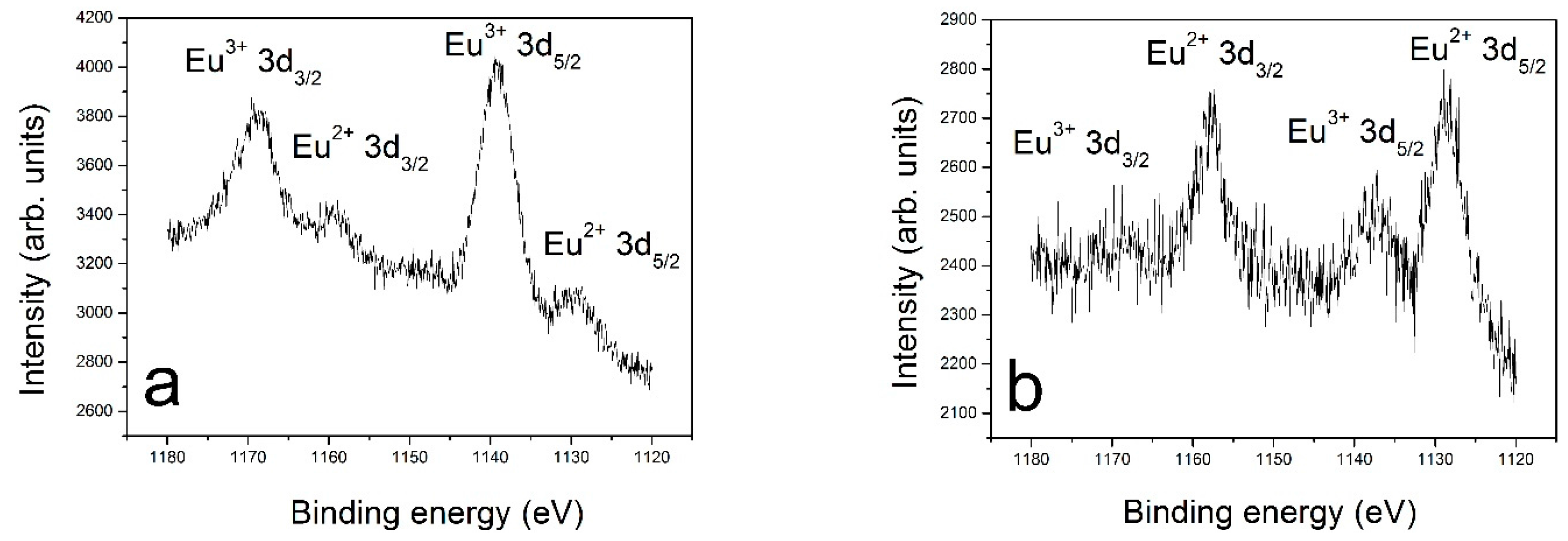
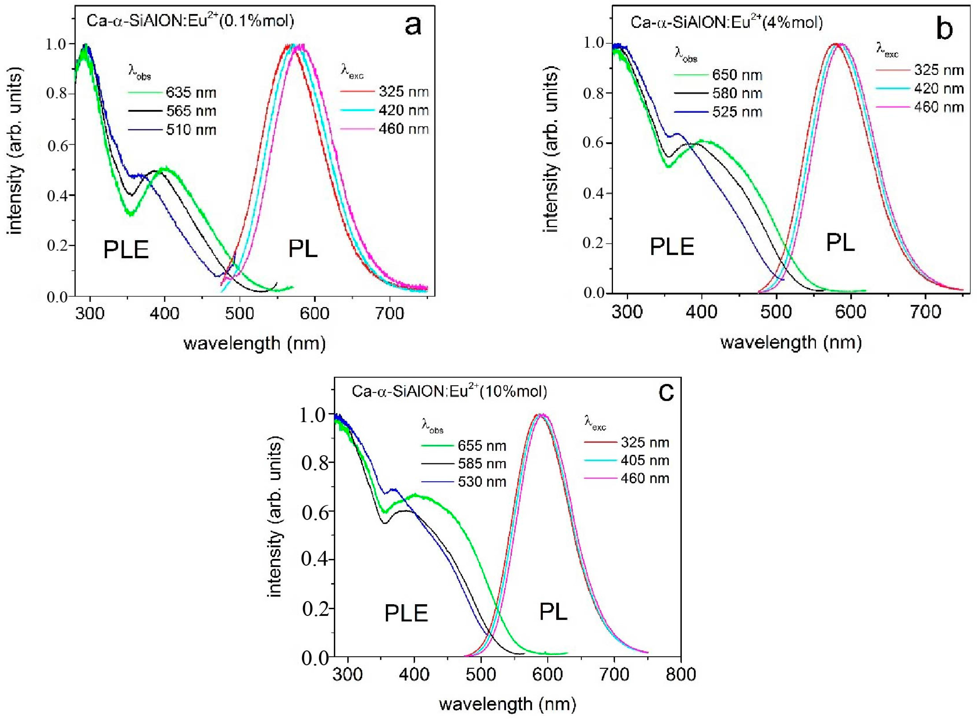
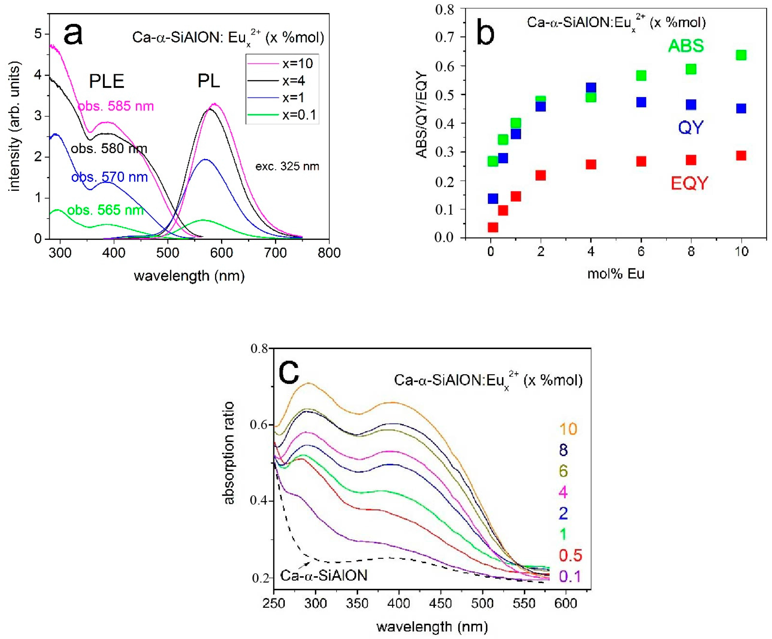
3.2. Basic Spectroscopy

The photoluminescence (PL) and photoluminescence excitation (PLE) spectra of Eu2+ doped Ca(0.8−x) EuxSi9.6Al2.4O0.8N15.2 samples with different concentration of Eu are shown in Figure 4a. The PLE spectra of all samples consist of two broad bands. One band has a peak located at approximately 300 nm which is associated with absorption of the host lattice Ca0.8Si9.6Al2.4O0.8N15.2 and the second with maximum at around 385 nm corresponds to the transitions between 4f7 the ground state and the excited states of the 4f65d1 configuration of Eu2+ions. The intensity of the PLE spectra first increases greatly from 0.1% up to 4% of Eu2+ concentrations and then does not change or only slightly increases up to 10% of Eu2+ concentration. The PL spectra of Ca(0.8−x) EuxSi9.6Al2.4O0.8N15.2 consist of a broad band in the range of 500 to 700 nm which is attributed to the transition between the lowest excited state of the 4f65d1 electronic configuration and the ground state of the 4f7 configurations of Eu2+ ion. The emission peak position shifts toward longer wavelengths with rising Eu2+ concentration from 565 nm (0.1 mol % Eu2+) to 585 nm (10 mol % Eu2+) and its intensity changes in the same manner as for PLE spectra. This optical characterization was reported earlier for Ca,Eu-α-sialon phosphor with similar composition [6,7,14,15,16,17,18,23,33,34,35,36,37,38,39,40,43]. Moreover, as it is discussed below, there is no clear relationship between AlN content and optical properties e.g.: the specimens with 0.1% and 4% of Eu2+ concentrations contain a similar amount of AlN but their PL properties are different. We would like to point out that Ca-α-sialon:Eu2+ powder without AlN contamination but with similar composition and method of manufacturing showed QY-56.83% [40], which is very close to our phosphor powder with 4 mol % Eu2+ (Figure 4b).
Figure 4b presents the absorption efficiency (ABS, green squares), quantum yield (QY, blue squares) and external quantum yield (EQY, red squares) of the Ca0.8Si9.6Al2.4O0.8N15.2 phosphor with different Eu2+ concentrations upon 420 nm excitation. The absorption efficiency of the phosphor is enhanced with the increase in the Eu2+ content as expected. External quantum yield which is the ratio of the number of photons emitted by the sample to the number of incident photons increases greatly up to 4 mol % of Eu2+ concentration and above slightly increases up to 10 mol % of Eu2+ concentration. Changes in EQY can be explained by the rise of absorption efficiency with the increase of Eu2+ concentration. EQY behavior is in good agreement with intensity changes observed in the PLE and PL spectra with the Eu2+ dopant concentration. Meanwhile the dependence of quantum yield (which is defined as ratio of the number of photons emitted to the absorbed ones) on Eu2+ concentration is unexpected. For low Eu2+ concentration this value is low and increases with concentration reaching maximum value at 4% of Eu2+ and above this value QY slightly decreases. Similar results, i.e., increase of ABS with rising Eu2+ concentration with simultaneous decreasing of QY were reported earlier [33], however their QY maximum value was attained at slightly lower Eu concentration of 3 mol %.
Normally, internal quantum yield losses are due to nonradiative processes that dissipate the absorbed energy without emitting photons and they are rather expected in samples with high Eu2+ concentrations. To explain this behavior we measured the absorption spectra of pure Ca0.8Si9.6Al2.4O0.8N15.2 host (dashed curve on Figure 4c). It is clearly visible that pure host (in the absence of emission) absorbs light over the whole considered spectral range. After absorption the energy of excitation is lost in a non-radiative processes. This host-related absorption significantly influences the correct QY measurement especially for low concentrations of doped Eu2+ ions and can explain the behavior which we observed in QY with the increase of Eu2+ concentration. The decrease of QY with increase of Eu2+ concentration above 4 mol % is related to excitation energy transfer from Eu2+ to the nonradiative recombination centers. This process will be discussed later in the paper.
Figure 5 presents the effect of excitation at different wavelengths on the normalized PL spectra and the effect of monitored luminescence at different wavelengths on the normalized PLE of Ca0.8Si9.6Al2.4O0.8N15.2:Eu2+ for samples Figure 5a with 0.1 mol % Eu2+, Figure 5b 4 mol % Eu2+ and Figure 5c 10 mol % Eu2+. It is visible that for all samples, illumination at different wavelengths (λexc = 325 nm, 405 nm, and 460 nm) affects the emission peak maximum in a way that longer excitation wavelengths produce emission peaks with maxima shifted toward longer wavelengths. This effect is most pronounced for the low concentrate sample (0.1 mol % Eu) in which at 325 nm excitation, emission peak maximum is observed at 566 nm and shifts up to 580 nm when excited at 460 nm. PLE spectra monitored at particular wavelengths show the same trend. Namely excitation spectra monitored luminescence at shorter (or longer) wavelengths than at the luminescence maximum, produces the 4f7→4f65d1 peak shifted to the shorter (or longer) wavelengths. In PLE the spectra band peak which is associated with absorption of the host lattice (Ca0.8Si9.6Al2.4O0.8N15.2) located at approximately 300 nm appear at the same wavelengths independently of the monitored luminescence energy. Such a shift of the PL band and PLE band is typical for the situation when we are dealing with Eu2+ multi-sites. The particular sites differ by the energy of the excited states of the 4f65d electronic configuration. It is interesting that the shift of the PLE band is much stronger then the shift of the PL bands.
To analyze this phenomenon one should consider that the excitation band is created by the transition to the excited state of the 4f65d electronic manifold which has the same spin (7/2) as the ground state, 8S, whereas the emission takes place always from the lowest states of the 4f65d electronic configuration. Since the 4f65d electronic configuration is formed by 4f6 electrons forming 7FJ states (spin 3) and d electron which can have spin ½, the effective spin for the 4f65d electronic configuration can be 7/2 and 5/2.

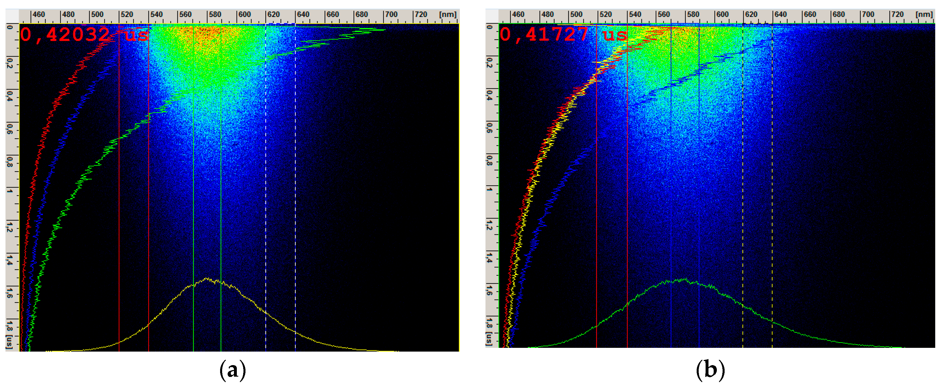
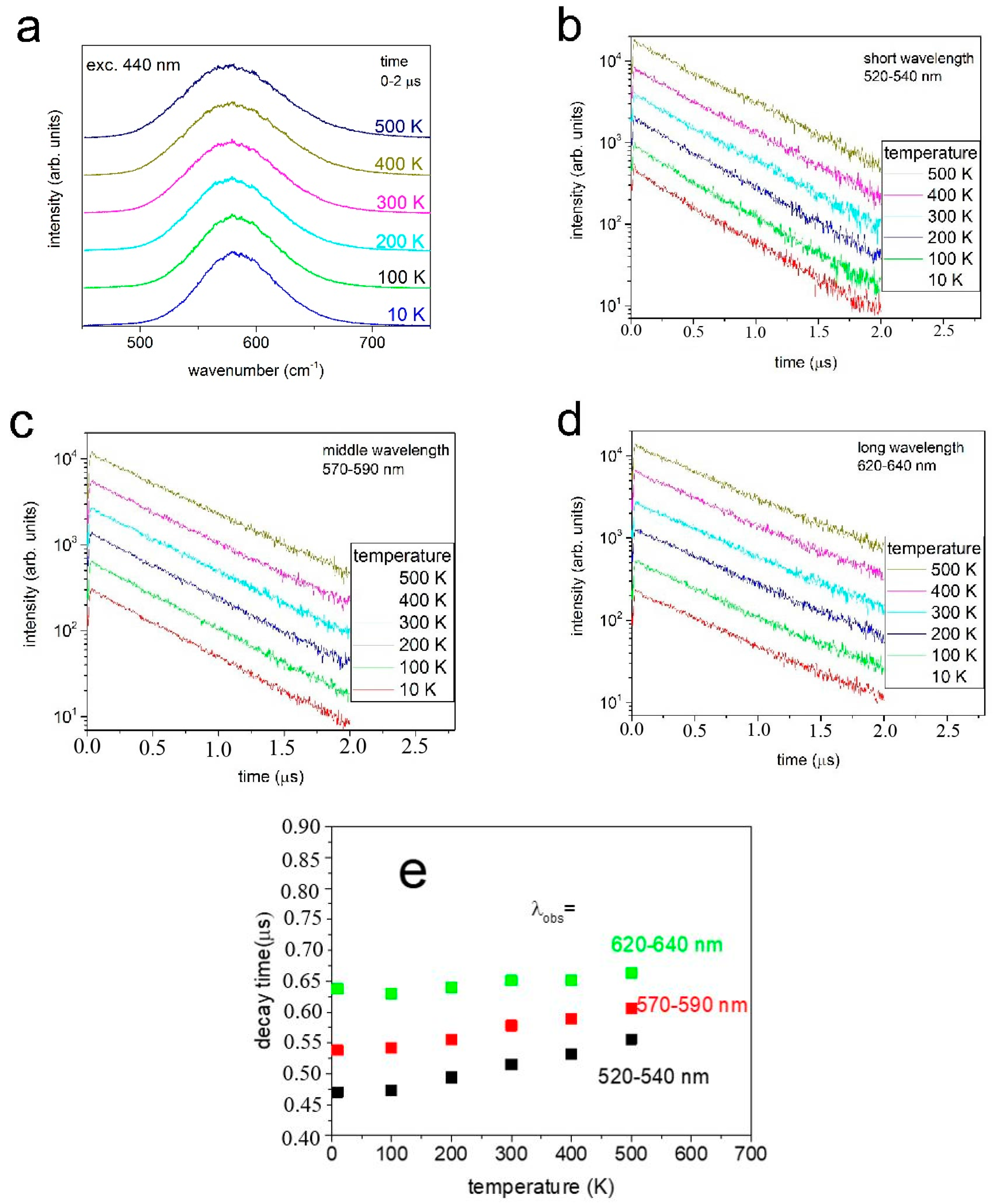
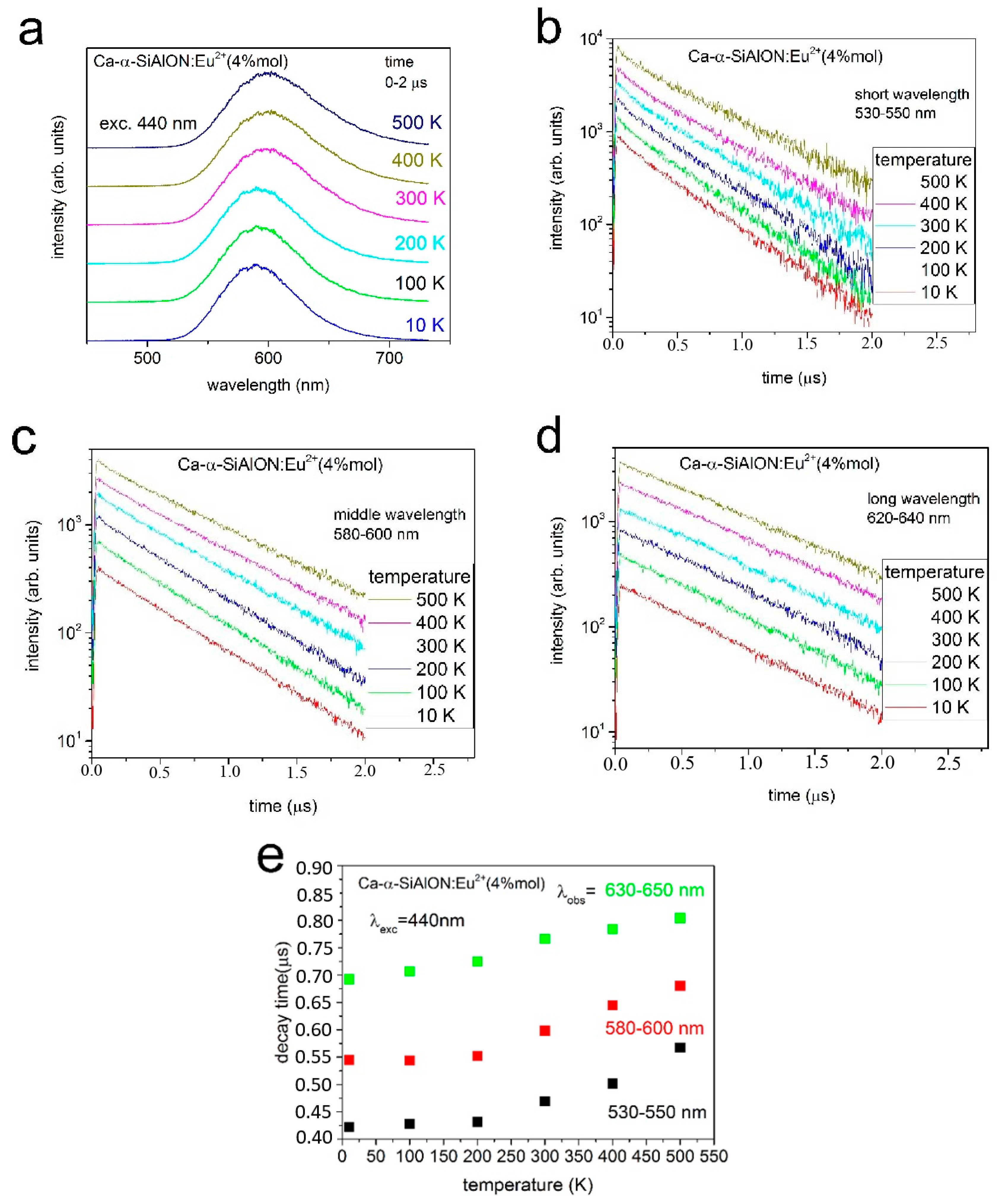
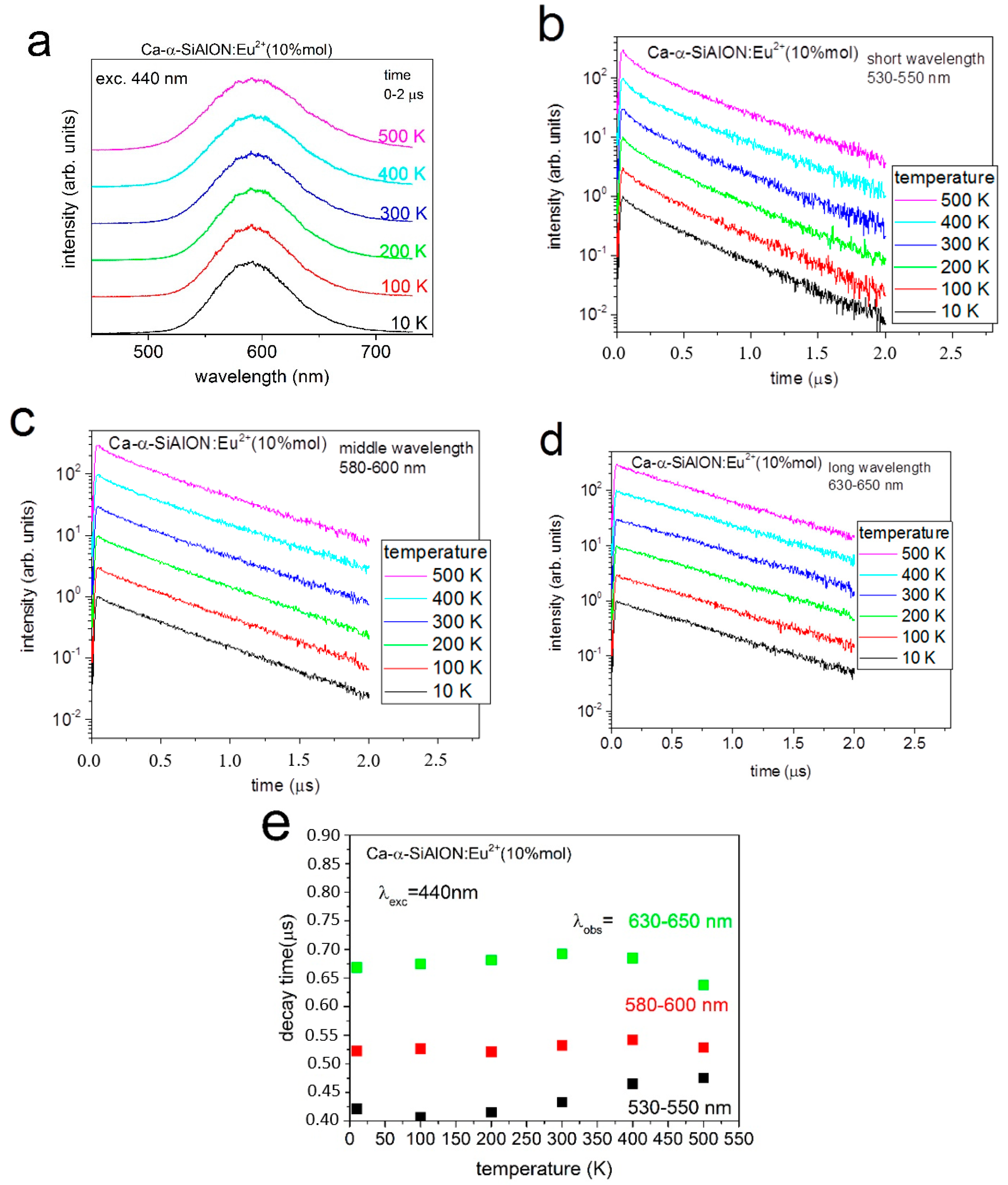
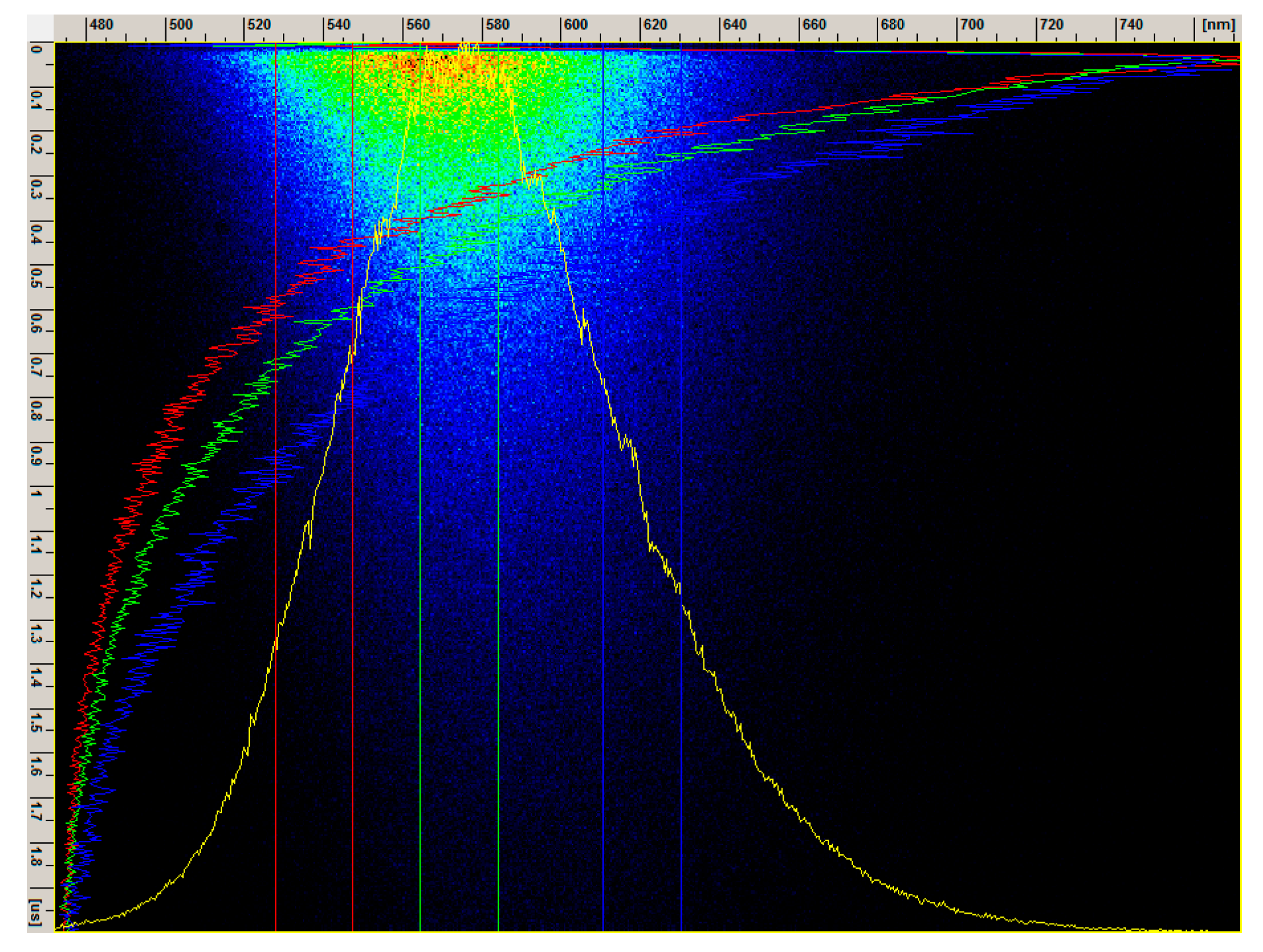
3.3. Time Resolved Spectroscopy

For more detailed consideration of the nonequivalent environment of Eu2+ centers the time-resolved luminescence spectra were measured. The main advantage of this technique is the possibility to observe spectral distribution and luminescence decay together. Figure 6a,b present the streak camera images obtained for Ca0.8Si9.6Al2.4O0.8N15.2:Eu2+ (0.1 mol %) under 440 nm pulse excitation at 10 K and 500 K.
The summary of results of TRES experiment performed in temperature range 10 and 500 K for sample Ca0.8Si9.6Al2.4O0.8N15.2:Eu2+ (0.1 mol %) with the lowest dopant concentration in the series are presented in Figure 6. Figure 6a presents luminescence spectra at different temperatures, collected in time scale 0–2 µs. At 10 K maximum of the emission band is 581 nm and FWHM (full width at half maximum) is 2284 cm−1. As the temperature increases, the maximum of the emission band shifts to higher energies and at 500 K is at 576 nm and the FWHM increases to 2990 cm−1 at 500 K.
The luminescence spectra under excitation 440 nm obtained at different temperatures for the samples contained 0.1, 4, and 10% mol Eu are presented in Figure 7a, Figure 8a, and Figure 9a, respectively. In all cases the spectra consist of broad bands peaked at 590 nm. Energies of the band maximum do not depend on temperature. One can observe only the temperature increase of the band half-widths.
Luminescence decay time increases with increasing temperature and also varies across the emission band. This phenomenon is presented on Figure 7b–e, Figure 8b–e, and Figure 9b–e. The decays are single exponential and the PL decay times are collated in Figure 7e.
Figure 7c shows the temperature dependence of luminescence decay profiles, collected over the wavelength range of 570–590 nm. The decay of short wavelength and long wavelength parts of the luminescence spectrum at different temperatures are presented in Figure 7b,d respectively. Figure 7e presents comparison of the decay times calculated by single exponential fit to the emission signal, collected in the three wavelength ranges listed above, obtained for the sample with 0.1 mol % of Eu. Figure 8b–e and Figure 9b–e present the results for the samples with 4 mol % and 10 mol % of Eu, respectively.
The dependence of the decay time on monitored wavelength supports the existence of many Eu2+ sites in the sample. Luminescence with shorter wavelength decays faster than luminescence with longer wavelength, that is in accordance with quantum mechanics which predicts that the radiative transition probability is proportional to third power of photon energy.
The increase of lifetime with increasing temperature is not a typical behavior of the luminescence centers and can be explained by thermally activated energy transfer processes. When the sites which are characterized by faster luminescence decay transfer the excitation energy to sites that are characterized by slower decay it causes the elongation of the averaged decay time. Such a process is activated thermally since increasing temperature yields an increase of spectral overlapping between the emission and absorption bands of donor and acceptor. It is visible in Figure 7b–d that the luminescence decay for the sample with 0.1 mol % concentration of Eu2+ is single exponential for all monitored wavelength whereas Figure 8b and Figure 9b,c show that the decays of luminescence with the shortest wavelength are not single exponential, the luminescence with long wavelength decay exponentially, for the samples with concentration of Eu2+ 4 mol % and 10 mol %. One can consider that the Eu2+ side with higher energy of the 4f65d state are donors and the Eu2+ sites with the lower energy of the 4f65d are acceptors. The “not single” exponential decay of the luminescence of the donors (higher energy of the luminescence) and single exponential PL decay of the acceptor (lower energy of the luminescence) is typical behavior for systems with excitation energy transfer. An additional conclusion is that the energy transfer increases when the Eu2+ concentration increases in the sample. This finding is consistent with the effect of various Eu2+ concentrations inside the crystal lattice and on the surface of sialon grains/particles. The present findings are contrary to results of Quansheng Wu et al. [34] claiming only one light luminescence center in oxygen-free Ca1.4Al2.8Si9.2N16:xEu or to the biexponential fit of the decay times in nitrogen-rich Ca-α-sialon:Eu2+ [35].

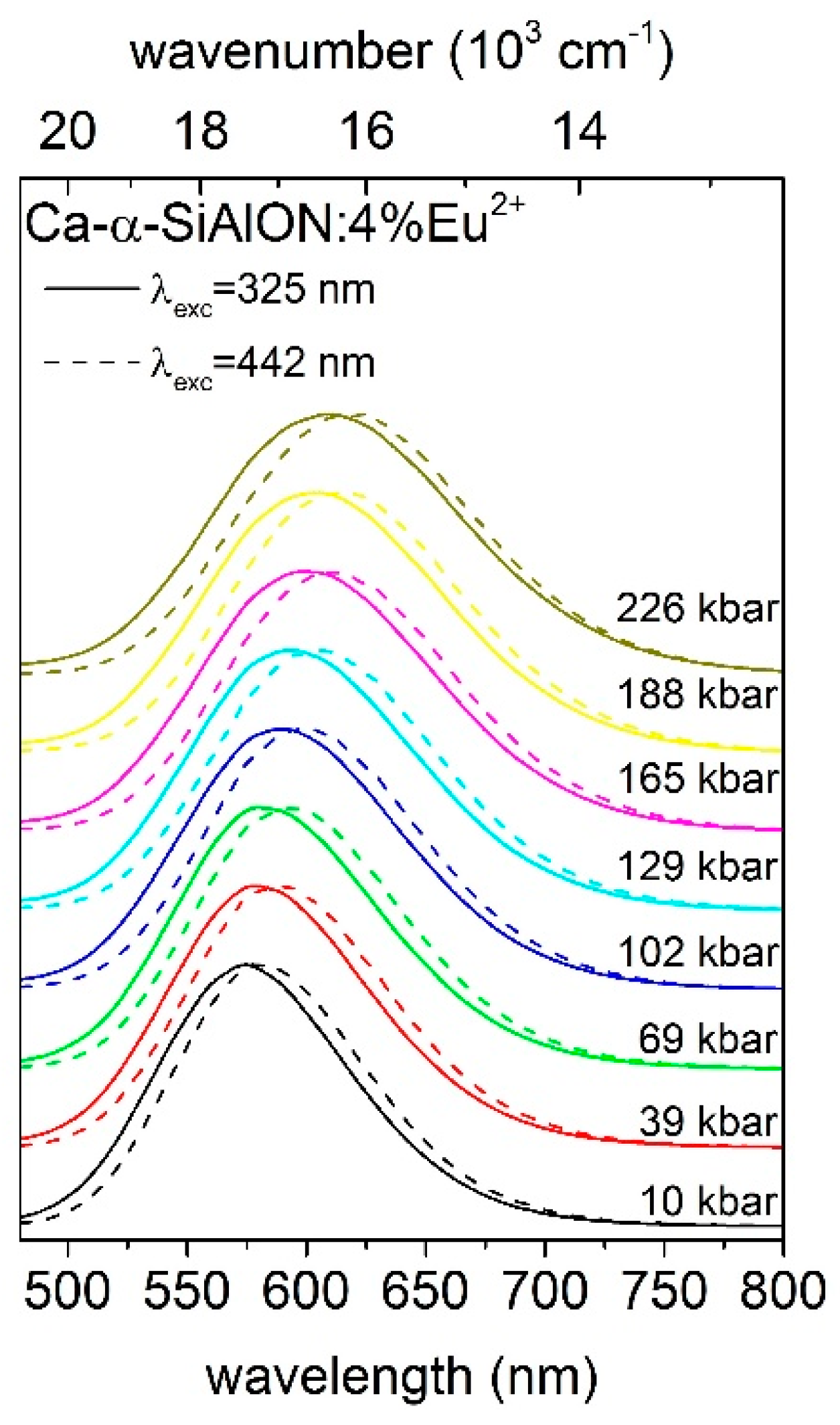
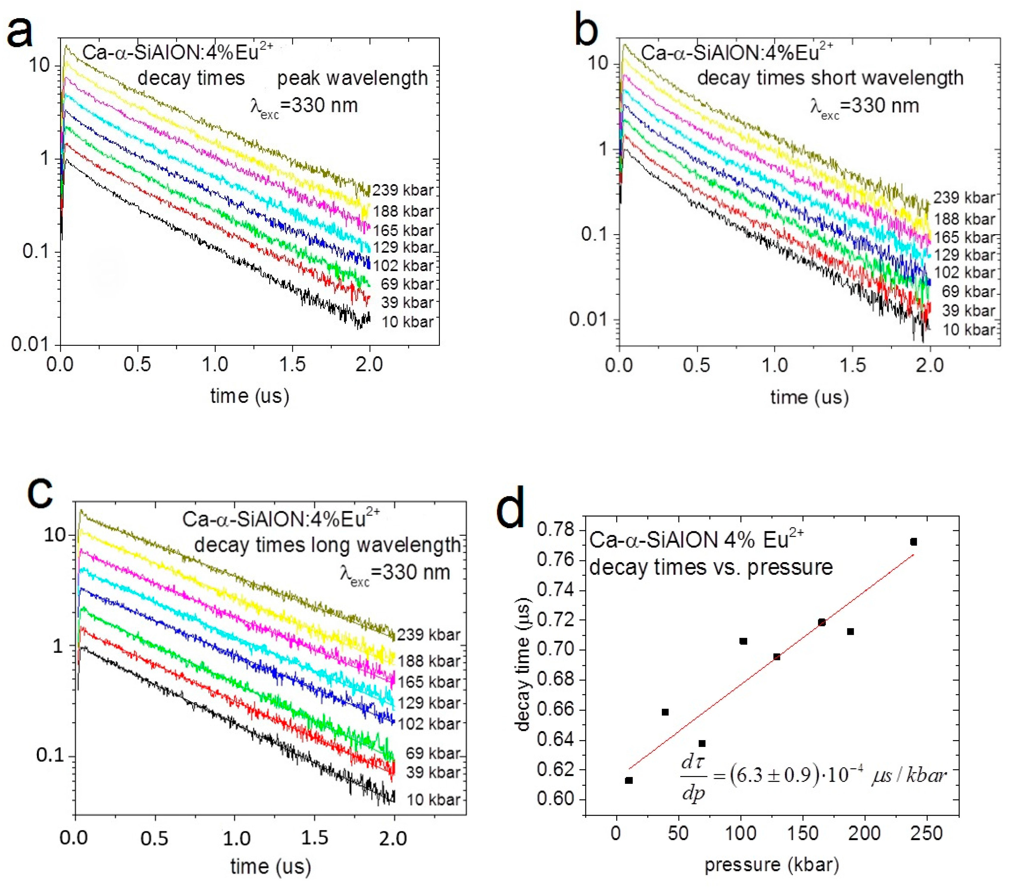
3.4. High Pressure Spectroscopy

The effect of non-single exponential decay is not very strong , therefore one can describe the luminescence decay using one parameter considered as average decay time calculated using the formula:
τ av = 1 I 0   0 I ( t ) dt
where I0 is the intensity of luminescence at t = 0. It can be seen from Figure 7e, Figure 8e, and Figure 9e that the average luminescence decay time increases with temperature and the increase is the strongest for the Eu2+ concentration equal to 4 mol %. Considering the samples with 0.1 mol % and 4 mol % of Eu2+ this effect means that energy transfer between Eu ions increases with increasing Eu content. On the other hand for the highest Eu concentration (10 mol %) evident decreasing of the luminescence decay time with increasing temperature for luminescence monitored at 580–600 nm and 630–650 nm is observed. This effect can be attributed to an increase of the probability of nonradiative processes. For the highest Eu2+ concentration many of the Eu3+ ions are close to the nonradiative centers and at temperature above 300 K the energy transfer to these centers becomes significant.
Actually there are two processes that control the luminescence decay. The energy transfer between the Eu2+ and energy transfer from Eu2+ to the nonradiative recombination centers. Both effects become more important when the concentration of Eu2+ ions increases. The increase of probability of energy transfer between Eu2+ ions is observed to increase if the Eu concentration is from 0.1 mol % to 4 mol %. In this range of concentration, transfer to the nonradiative centers is not observed. It is probably too weak in comparison to the transfer between the Eu2+ ions. However when the Eu2+ concentration reaches 10 mol % energy transfer from Eu2+ to nonradiative recombination centers become important and yield a decrease of Eu2+ lifetime at temperatures above 300 K. It should be noted that the increase of the probability of energy transfer from Eu2+ ions to the nonradiative centers for concentration of Eu larger than 4 mol % explains also the diminishing QY of the system presented in Figure 4b.
Figure 10 shows the pressure dependence of PL spectra of Ca0.8Si9.6Al2.4O0.8N15.2:4%Eu2+ at pressure ranging from ambient up to 230 kbar. PL spectra were excited with 325 and 442 nm. PL spectra exhibit the spectral shifts towards longer wavelengths with increasing pressure. The PL spectra excited with 442 nm are consistently shifted toward longer wavelengths, with respect to PL spectra excited with 325 nm. The PL peak position shifts linearly towards lower energies with increasing pressure. The rate of pressure shifts of PL excited with 325 and 442 nm, are equal to 4.28 and 4.47 cm−1/kbar, respectively. Both values are the same within the uncertainty range of the measurement. This red shift of the luminescence band with increasing pressure is related to a pressure induced increase of the crystal field splitting of the 4f65d electronic manifold and diminishing energy of the emitting state.
Figure 11 shows the streak camera image of time resolved emission spectra measurement of Ca0.8Si9.6Al2.4O0.8N15.2:Eu2+ (4 mol %). The spectral and time windows marked by red, green and blue rectangles were used to calculate the decay profiles of Ca0.8Si9.6Al2.4O0.8N15.2:Eu2+ (4 mol %) luminescence at different parts of the emission spectrum—short wavelength, peak position wavelength, and long wavelength, respectively. Decay profiles taken at these regions at different pressures are significantly different and are presented in Figure 12a–c. The decays at short wavelength of the spectrum are to some degree nonexponential. The slope of the decay profiles changes, being the greatest in the short wavelength region of the spectrum and gradually decreasing when moving towards longer wavelengths. The decay profile at the long wavelength part of the spectrum is virtually single exponential, which allows the pressure dependence of the decay times of luminescence using single exponential fitting to be calculated. The decay time values vs. pressure, obtained from single exponential fit in Figure 12c are presented in Figure 12d. The decay times of luminescence exhibit a gradual increase with increasing pressure at a rate equal to 6.3 × 10⁻⁴ kb/kbar.
The non-exponential decay of the luminescence from the short wavelength part of the spectrum and from the maximum of the PL band and single exponential decay of the PL with the longest wavelength confirms the effect of the excitation energy transfer between the Eu2+ ions, mentioned above.

4. Conclusions

Ca,Eu-α-sialon powders of the designed formula of EuxCa(0.8−x)Si9.6Al2.4O0.8N15.2 (m = 1.6, n = 0.8) were manufactured in flowing nitrogen in a graphite furnace at 1650 °C. The resultant phosphor powders were contaminated by a small amount of AlN. The chemical composition of the resultant sialon grains/particles deviates from a designed one in such a way that smaller (m+n) and n values were attained thus the composition shifted into the α-Si3N4 rich corner. Replacement of Ca2+ by Eu2+ in the α-sialon structure resulted in the expansion of the crystal lattice up to 6 mol % Eu. XPS studies of phosphor particles showed a notable difference between their thin oxidized surface and the underlying sialon grains. Both oxidation states of Eu cations were detected on the particles surface and a significant Eu concentration increase on the particle surface was confirmed.
We have shown that Eu2+ ions occupy many nonequivalent sites that differ in the energy of the emitting 4f65d state. The homogenous broadening of the PL spectrum, which is related to the electron-lattice interaction, does not allow different sites from PL and PLE spectra to be distinguished. On the other hand the evident dependence of the energy PLE band on the monitored PL wavelength shows the existence of different sites. We showed that there is excitation energy transfer from sites with higher energy of 4f65d to sites with lower energy of the 4f65d state. Additionally for 10 mol % of Eu2+ the energy transfer for the Eu2+ ions to the nonradiative centers is responsible for diminishing luminescence decay with increasing temperature. This process is also responsible for the diminishing QY of the system.
We can present a model of energy transfer between Eu2+ ions and Eu2+ ions and nonradiative centers. The model is presented in Figure 13. It is seen that energy transfer between the Eu2+ ions takes place consecutively, from the Eu2+ with higher energy of the 4f65d state to the sites with lower energy of the 4f65d state. One can observe that effective transfer cannot take place when the difference between the energy of the 4f65d states in the two sites is too large because of the small overlapping between the emission and absorption bands. Additionally our results show that transfer to the nonradiative centers although it can take place from all Eu2+ ions, is most probable from the Eu3+ ions which are characterized by the lowest energy of the 4f65d state. Such a conclusion can be drawn since the diminishing of the luminescence lifetime with increasing temperature is largest for luminescence monitored at 630–650nm (see Figure 9e).
High pressure PL measurements confirmed the multisite Eu2+ in the samples. We observed a pressure induced red shift of the Eu2+ PL band with a rate approximately equal to 4.35 cm−1/kbar. This is rather a small rate in comparison to other materials doped with Eu2+, which is usually two times larger [43].

Acknowledgments

This paper was supported by the Polish National Center for Research and Development with grants No: PBS3/A5/48/2015.

Author Contributions

The manuscript was prepared through contributions of all authors. All authors have given approval to the final version of the manuscript. Daniel Michalik conceived and designed the experiments of phosphor manufacturing, analyzed EDS and XRD data as well as solved and refined the reported structures Tomasz Pawlik performed the experiments of phosphor manufacturing and their chemical analysis, Benedykt Kukliński performed the spectroscopic experiments, Agata Lazarowska performed the emission and excitation spectra and analyzed the data, Tadeusz Leśniewski performed the spectroscopic measurements under high hydrostatic pressure and analyzed the data, Justyna Barzowska contributed in designation, performing and analyzing the spectroscopic measurements, Sebastian Mahlik analyzed the spectroscopic data, Marek Grinberg contributed partly by planning the spectroscopic experiments and the interpretation of the results, Barbara Adamczyk collected X-ray data, Mateusz Pławecki performed XPS studies and interpreted the data, Mateusz Sopicka-Lizer contributed to design of the experiments, Sebastian Mahlik, Agata Lazarowska, Marek Grinberg and Małgorzata Sopicka-Lizer contributed in writing the manuscript.

Conflicts of Interest

The authors declare no conflict of interest.

References

  1. Xie, R.J.; Hirosaki, N. Silicon-based oxynitride and nitride phosphors for white LEDs-A review. Sci. Technol. Adv. Mater. 2007, 8, 588–600. [Google Scholar] [CrossRef]
  2. Ye, S.; Xiao, F.; Pan, Y.X.; Ma, Y.Y.; Zhang, Q.Y. Phosphors in phosphor-converted white light-emitting diodes: Recent advances in materials, techniques and properties. Mater. Sci. Eng. R 2010, 71, 1–34. [Google Scholar] [CrossRef]
  3. Xie, R.J.; Hirosaki, N.; Takeda, T. Highly reliable white LEDs using nitride phosphors. J. Korean Ceram. Soc. 2012, 49, 375–379. [Google Scholar] [CrossRef]
  4. Xie, R.J.; Hintzen, H.T. Optical properties of (oxy)nitride materials: A review. J. Am. Ceram. Soc. 2013, 96, 665–687. [Google Scholar] [CrossRef]
  5. Xia, Z.; Xu, Z.; Chen, M.; Liu, Q. Recent developments in the new inorganic solid state LED phosphors. Dalton Trans. 2016, 45, 11214–11232. [Google Scholar] [CrossRef] [PubMed]
  6. Van Krevel, J.W.H.; Van Rutten, J.W.T.; Mandal, H.; Hintzen, H.T.; Metselaar, R. Luminescence properties of terbium-, cerium-, or europium-doped α-sialon materials. J. Solid State Chem. 2002, 165, 19–24. [Google Scholar] [CrossRef]
  7. Xie, R.; Mitomo, M.; Uheda, K.; Xu, F.-F.; Akimune, Y. Preparation and luminescence spectra of calcium-and rare-earth (R = Eu, Tb, and Pr)-Codoped α-SiAlON ceramics. J. Am. Ceram. Soc. 2002, 85, 1229–1234. [Google Scholar] [CrossRef]
  8. Hirosaki, N.; Xie, R.J.; Kimoto, K.; Sekiguchi, T.; Yamamoto, Y.; Suehiro, T.; Mitomo, M. Characterization and properties of green-emitting b-SiAlON: Eu2+ powder phosphors for white light-emitting diodes. Appl. Phys. Lett. 2005, 86, 211905. [Google Scholar] [CrossRef]
  9. Bachmann, V.; Ronda, C.; Oeckler, O.; Schnick, W.; Meijerink, A. Color point tuning for (Sr,Ca,Ba)Si2O2N2:Eu2+ for white light LEDs. Chem. Mater. 2009, 21, 316–325. [Google Scholar] [CrossRef]
  10. Li, Y.Q.; de With, G.; Hintzen, H.T. The effect of replacement of Sr by Ca on the structural and luminescence properties of the red-emitting Sr2Si5N8:Eu2+ LED conversion phosphor. J. Solid State Chem. 2008, 181, 515–524. [Google Scholar] [CrossRef]
  11. Li, Y.Q.; Hirosaki, N.; Xie, R.-J.; Takada, T.; Yamamoto, Y.; Mitomo, M.; Shioi, K. Synthesis, crystal and local electronic structures, and photoluminescence properties of red-emitting CaAlzSiN2+z:Eu2+ with orthorhombic structure. Int. J. Appl. Ceram. Technol. 2010, 7, 787–802. [Google Scholar] [CrossRef]
  12. Li, Y.Q.; Delsing, A.C.A.; De With, G.; Hintzen, H.T. Luminescence properties of Eu2+-activated alkaline-earth silicon-oxynitride MSi2O2-δN2+2/3δ (M = Ca, Sr, Ba): A promising class of novel LED conversion phosphors. Chem. Mater. 2005, 17, 3242–3248. [Google Scholar] [CrossRef]
  13. Search, H.; Journals, C.; Contact, A.; Iopscience, M.; Address, I.P. Luminescence properties of SrSi6N8:Eu2+. J. Mater. Sci. 2012, 75502, 2–7. [Google Scholar]
  14. Xie, R.J.; Hirosaki, N.; Sakuma, K.; Yamamoto, Y.; Mitomo, M. Eu2+-doped Ca-α-SiAlON: A yellow phosphor for white light-emitting diodes. Appl. Phys. Lett. 2004, 84, 5404. [Google Scholar] [CrossRef]
  15. Suehiro, T.; Hirosaki, N.; Xie, R.J.; Mitomo, M. Powder synthesis of Ca-α′-SiAlON as a host material for phosphors. Chem. Mater. 2005, 17, 308–314. [Google Scholar] [CrossRef]
  16. Xie, R.J.; Hirosaki, N.; Mitomo, M.; Suehiro, T.; Xu, X.; Tanaka, H. Photoluminescence of rare-earth-doped Ca-α-SiAlON phosphors: Composition and concentration dependence. J. Am. Ceram. Soc. 2005, 88, 2883–2888. [Google Scholar] [CrossRef]
  17. Li, H.L.; Hirosaki, N.; Xie, R.J.; Suehiro, T.; Mitomo, M. Fine yellow alpha-SiAlON:Eu phosphors for white LEDs prepared by the gas-reduction-nitridation method. Sci. Technol. Adv. Mater. 2007, 8, 601–606. [Google Scholar] [CrossRef]
  18. Suehiro, T.; Hirosaki, N.; Xie, R.J.; Sakuma, K.; Mitomo, M.; Ibukiyama, M.; Yamada, S. One-step preparation of Ca-alpha-SiAlON:Eu2+ fine powder phosphors for white light-emitting diodes. Appl. Phys. Lett. 2008, 92, 191904. [Google Scholar] [CrossRef]
  19. Cao, G.Z.; Metselaar, R. Alpha’-Sialon Ceramics—A Review. Chem. Mater. 1991, 3, 242–252. [Google Scholar] [CrossRef]
  20. Ekström, T.; Nygren, M. SiAION Ceramics. J. Am. Ceram. Soc. 1992, 75, 259–276. [Google Scholar] [CrossRef]
  21. Izumi, F.; Mitomo, M.; Suzuki, J. Structure refinement of yttrium α-sialon from X-ray powder profile data. J. Mater. Sci. Lett. 1982, 1, 533–535. [Google Scholar] [CrossRef]
  22. Li, Y.Q.; Hirosaki, N.; Xie, R.-J.; Takeda, T.; Mitomo, M. Photoluminescence properties of rare earth doped α-Si3N4. J. Lumin. 2010, 130, 1147–1153. [Google Scholar] [CrossRef]
  23. Wu, Q.; Ding, J.; Wang, X.; Li, Y.; Wang, Y. Structure modification and covalence variation induced by cation substitution in pure nitride Ca-α-sialon phosphor. Mater. Res. Bull. 2016, 83, 649–656. [Google Scholar] [CrossRef]
  24. Shioi, K.; Hirosaki, N.; Xie, R.-J.; Takeda, T.; Li, Y.Q. Synthesis, crystal structure and photoluminescence of Eu-α-SiAlON. J. Alloy. Compd. 2010, 504, 579–584. [Google Scholar] [CrossRef]
  25. Shioi, K.; Hirosaki, N.; Xie, R.-J.; Takeda, T.; Li, Y.Q.; Matsushita, Y. Synthesis, crystal structure, and photoluminescence of Sr-α-SiAlON:Eu2+. J. Am. Ceram. Soc. 2010, 93, 465–469. [Google Scholar] [CrossRef]
  26. Redington, M.; O’Reilly, K.; Hampshire, S. On the relationships between composition and cell dimensions in alpha-sialons. J. Mater. Sci. Lett. 1991, 10, 1228–1231. [Google Scholar] [CrossRef]
  27. Van Rutten, J.W.T.; Hintzen, H.T.; Metselaar, R. Phase formation sintering of Ca-alpha-sialon by reaction sintering. J. Eur. Ceram. Soc. 1996, 16, 995–999. [Google Scholar] [CrossRef]
  28. Mandal, H. New developments in -SiAlON ceramics. J. Eur. Ceram. Soc. 1999, 19, 2349–2357. [Google Scholar] [CrossRef]
  29. Huang, Z.K.; Tien, T.Y. Solid-liquid reaction in the system Si3N4-Y3Al5O12-Y2Si2O7 under 1 MPa of nitrogen. J. Am. Ceram. Soc. 1994, 77, 2763–2766. [Google Scholar] [CrossRef]
  30. Xu, X.; Tang, J.; Nishimura, T.; Hao, L. Synthesis of Ca-alpha-SiAlON phosphors by a mechanochemical activation route. Acta Mater. 2011, 59, 1570–1576. [Google Scholar] [CrossRef]
  31. Becher, P.F.; Painter, G.S.; Shibata, N.; Satet, R.L.; Hoffmann, M.J.; Pennycook, S.J. Influence of additives on anisotropic grain growth in silicon nitride ceramics. Mater. Sci. Eng. A 2006, 422, 85–91. [Google Scholar] [CrossRef]
  32. Jiang, J.; Wang, P.; He, W.; Chen, W.; Zhuang, H.; Cheng, Y.; Yan, D. Self-propagating high-temperature synthesis of alpha-SiAlON doped by RE (RE = Eu, Pr, Ce) and codoped by RE and Yttrium. J. Am. Ceram. Soc. 2004, 87, 703–705. [Google Scholar] [CrossRef]
  33. Sakuma, K.; Hirosaki, N.; Xie, R.J. Red-shift of emission wavelength caused by reabsorption mechanism of europium activated Ca-α-SiAlON ceramic phosphors. J. Lumin. 2007, 126, 843–852. [Google Scholar] [CrossRef]
  34. Wu, Q.; Wang, Y.; Yang, Z.; Que, M.; Li, Y.; Wang, C. Synthesis and luminescence properties of pure nitride Ca-α-sialon with the composition Ca1.4Al2.8Si9.2N16 by gas-pressed sintering. J. Mater. Chem. C 2014, 2, 829–834. [Google Scholar] [CrossRef]
  35. Park, W.J.; Song, Y.H.; Moon, J.W.; Kang, S.M.; Yoon, D.H. Synthesis and luminescent properties of Eu2+ doped nitrogen-rich Ca-alpha-SiAlON phosphor for white light-emitting diodes. Solid State Sci. 2010, 12, 1853–1856. [Google Scholar] [CrossRef]
  36. Piao, X.; Machida, K.; Horikawa, T.; Hanzawa, H. Synthesis and luminescent properties of low oxygen contained Eu2+-doped Ca-α-SiAlON phosphor from calcium cyanamide reduction. J. Rare Earth. 2008, 26, 198–202. [Google Scholar] [CrossRef]
  37. Yang, Z.; Wang, Y.; Zhao, Z. Synthesis, structure and photoluminescence properties of fine yellow-orange Ca-α-SiAlON: Eu2+ phosphors. J. Alloy. Compd. 2012, 541, 70–74. [Google Scholar] [CrossRef]
  38. Sakuma, K.; Hirosaki, N.; Xie, R.J.; Yamamoto, Y.; Suehiro, T. Optical properties of excitation spectra of (Ca,Y)-alpha-SiAlON:Eu yellow phosphors. Physica Status Solidi C Conf. 2006, 3, 2701–2704. [Google Scholar] [CrossRef]
  39. Sakuma, K.; Hirosaki, N.; Xie, R.J.; Yamamoto, Y.; Suehiro, T. Luminescence properties of (Ca,Y)-alpha-SiAlON:Eu phosphors. Mater. Lett. 2007, 61, 547–550. [Google Scholar] [CrossRef]
  40. Park, S.S.; Jang, B.Y.; Park, J.S.; Nahm, S. Crystal structures and luminescence properties of AlN-deficient Eu2+—Activated Ca-alpha-SiAlON phosphor. J. Korean Phys. Soc. 2010, 57, 990–993. [Google Scholar]
  41. Pawlik, T.; Michalik, D.; Sopicka-Lizer, M.; Lisiecki, R.; Adamczyk, B.; Pławecki, M.; Mieszczak, Ł.; Walerczyk, W. Luminescence properties of the Ca-alpha-sialon:Eu solid solution. Opt. Mater. 2016, 59, 43–48. [Google Scholar] [CrossRef]
  42. Pawlik, T.; Michalik, D.; Sopicka-Lizer, M.; Serkowski, S. Influence of m and n parameters of Ca- α-sialon: Eu solid solution on phosphor’s optical properties. Adv. Sci. Technol. 2014, 90, 149–156. [Google Scholar] [CrossRef]
  43. Chung, C.-C.; Jean, J.-H. Synthesis of Ca-α-SiAlON:Eux phosphor powder by carbothermal-reduction–nitridation process. Mater. Chem. Phys. 2010, 123, 13–15. [Google Scholar] [CrossRef]
  44. Cho, E.-J.; Oh, S.-J. Surface valence transition in trivalent Eu insulating compounds observed by photoelectron spectroscopy. Phys. Rev. B 1999, 59, 15613–15616. [Google Scholar] [CrossRef]
  45. Burian, W.; Szade, J.; O’Keevan, T.; Celiński, Z. Photoemission study of Eu valency in EuF3 ultrathin buried layers and single crystals. Phys. Status Solidi B 2004, 241, R15–R18. [Google Scholar] [CrossRef]
  46. Dhoble, S.J.; Nagpure, I.M.; Dhoble, N.S.; Molina, P. Effect of Bi ion on Eu2+ ↔ Eu3+ conversion in CaF2:Eu phosphors for RPL dosimetry. J. Mater. Sci. 2011, 46, 7253–7261. [Google Scholar] [CrossRef]
  47. Gao, G.; Reibstein, S.; Peng, M.; Wondraczek, L. Tunable dual-mode photoluminescence from nanocrystalline Eu-doped Li2ZnSiO4 glass ceramic phosphors. J. Mater. Chem. 2011, 21, 3156. [Google Scholar] [CrossRef]
  48. Maślankiewicz, P.; Szade, J.; Winiarski, A.; Daniel, P. Bridgman-Stockbarger growth and X-ray photoelectron spectroscopy study of LiY1-xEuxF4 crystals. Cryst. Res. Technol. 2005, 40, 410–418. [Google Scholar] [CrossRef]
  49. Pawlik, T.; Michalik, D.; Sopicka-Lizer, M.; Lisiecki, R. Effect of AlF3 and HBO3 fluxes on the structure and optical properties of Ca-α-sialon:Eu2+ phosphor powders. Inżynieria Materiałowa 2016, 37, 35–40. [Google Scholar]
  50. Shannon, R.D. Revised effective ionic radii and systematic studies of interatomic distances in halides and chalcogenides. Acta Crystallogr. A 1976, 32, 751–767. [Google Scholar] [CrossRef]
  51. Mezzi, A.; Kaciulis, S.; Cacciotti, I.; Bianco, A.; Gusmano, G.; Lamastra, F.R.; Fragalà, M.E. Structure and composition of electrospun titania nanofibres doped with Eu. Surf. Interface Anal. 2010, 42, 572–575. [Google Scholar] [CrossRef]
  52. Vercaemst, R.; Poelman, D.; Van Meirhaeghe, R.L.; Fiermans, L.; Laflère, W.H.; Cardon, F. An XPS study of the dopants’ valence states and the composition of CaS1−xSex:Eu and SrS1−xSex:Ce thin film electroluminescent devices. J. Lumin. 1995, 63, 19–30. [Google Scholar] [CrossRef]
Figure 1. X-ray diffraction patterns of Ca(0.8−x)EuxSi9.6Al2.4O0.8N15.2 phosphors (0 < x < 0.08). Asterisk indicates AlN related peaks.
Crystals 07 00342 g001
Figure 2. XPS survey spectrum of Eu-4 mol %-sialon of the as-received powder (bottom line) and after 1 minute Ar ions etching (upper line).
Crystals 07 00342 g002
Figure 3. The Eu 3d high resolution XPS spectrum of Eu-4 mol % sialon phosphor of the as-received powder (a) and after 2 min etching of Ar ions (b).
Crystals 07 00342 g003
Figure 4. (a) Room temperature photoluminescence (PL) spectra of Ca0.8Si9.6Al2.4O0.8N15.2:xEu2+ x [mol %] excited at 325 nm. Photoluminescence excitation (PLE) spectra of Ca0.8Si9.6Al2.4O0.8N15.2:xEu2+ observed at the maximum of luminescence band. (b) Quantum yield (QY), absorption efficiency (ABS) and external quantum yield (EQY) of Ca0.8Si9.6Al2.4O0.8N15.2:xEu2+ obtained under 420 nm excitation. (c) absorption spectra of Ca0.8Si9.6Al2.4O0.8N15.2:xEu2+.
Crystals 07 00342 g004
Figure 5. Room temperature photoluminescence (PL) spectra of Ca0.8Si9.6Al2.4O0.8N15.2:Eu2+ (x mol %) excited at different excitation wavelength and photoluminescenceexcitation (PLE) spectra of C Ca0.8Si9.6Al2.4O0.8N15.2:Eu2+ observed at different emission wavelength for (a) sample with 0.1 mol % Eu (b) sample 4 mol % Eu and (c) sample 10 mol % Eu.
Crystals 07 00342 g005
Figure 6. Time resolved luminescence spectra of Ca0.8Si9.6Al2.4O0.8N15.2:Eu2+ (0.1 mol %) excited with 440 nm at temperature 10 K (a) and 500 K (b) the abscissa represents the wavelength , the ordinate time scale. The curves represent the spectra and the PL decays.
Crystals 07 00342 g006
Figure 7. (a) Time resolved luminescence spectra of Ca0.8Si9.6Al2.4O0.8N15.2:Eu2+ (0.1 mol %) observed in the time range 0–2 μs, excited with 440 nm at various temperature. (bd) Luminescence decay curves of Ca0.8Si9.6Al2.4O0.8N15.2 Eu2+ (0.1 mol %,) excited with 440 nm at different temperatures. Luminescence decays are monitored at three region of wavelength (b) 520–540 nm (c) 530–550 nm and (d) 570–590 (e) Decay times calculated by single exponential fit of decay profiles for the selected region of luminescence wavelength.
Crystals 07 00342 g007
Figure 8. (a) Time resolved luminescence spectra of Ca0.8Si9.6Al2.4O0.8N15.2:Eu2+ (4 mol %) observed in the time range 0–2 μs, excited with 440 nm at various temperature. (bd) Luminescence decay curves of Ca0.8Si9.6Al2.4O0.8N15.2:Eu2+ (4 mol %) excited with 440 nm at different temperatures. Luminescence decays are monitored at three region of wavelength (b) 530–550 nm (c) 580–600 nm (d) 630–650 nm (marked with rectangles) (e) Decay times calculated by single exponential fit of decay profiles for the selected region of luminescence wavelength.
Crystals 07 00342 g008
Figure 9. (a) Time resolved luminescence spectra of Ca0.8Si9.6Al2.4O0.8N15.2:Eu2+ (10 mol %) observed in the time range 0–2 μs, excited with 440 nm at various temperature. (bd) Luminescence decay curves of Ca0.8Si9.6Al2.4O0.8N15.2:Eu2+ (10 mol %) excited with 440 nm at different temperatures. Luminescence decays are monitored at three region of wavelength (b) 530–550 nm (c) 580–600 nm (d) 630–650 nm (marked with rectangles) (e) Decay times calculated by single exponential fit of decay profiles for the selected region of luminescence wavelength.
Crystals 07 00342 g009
Figure 10. Pressure dependent emission spectra of Ca0.8Si9.6Al2.4O0.8N15.2:4%Eu2+. excited at 325 nm (solid line) and 442 nm (dashed line).
Crystals 07 00342 g010
Figure 11. Time resolved luminescence spectra of Ca0.8Si9.6Al2.4O0.8N15.2:Eu2+ (4 mol %) excited with 330 nm at pressure 10 kbar. The red, green, and blue region are the spectral windows used to acquire decay profiles at the short wavelength, peak wavelength, and long wavelength region of the spectrum, respectively.
Crystals 07 00342 g011
Figure 12. (a) Decay profiles of Ca0.8Si9.6Al2.4O0.8N15.2:4% Eu2+vs. pressure taken at peak wavelength. (b) Decay profiles of Ca0.8Si9.6Al2.4O0.8N15.2:4% Eu2+ vs. pressure taken at short wavelengths. (c) Decay profiles of Ca0.8Si9.6Al2.4O0.8N15.2:4% Eu2+ vs. pressure taken at long wavelengths (near the right HWHM point). (d) Decay times of long wavelength luminescence vs. pressure.
Crystals 07 00342 g012
Figure 13. Diagram representing the energy transfer between the Eu2+ ions (represented by the ground 4f7 and excited states 4f65d) in Ca,Eu-α-sialon and between the Eu2+ ions and nonradiative centers.
Crystals 07 00342 g013
Table 1. Phase composition and lattice parameters of the samples with various amount of Eu.
Eu [at %]Phase Composition [wt %]Unit Cell [Å]Volume [Å3]Crystallite Size [nm]
Ca-α-sialonAlNac
REF 7.838(0)5.703(0)350.3595
0.198.41.67.840(5)5.701(3)350.478574 ± 1
298.41.67.842(2)5.702(6)350.710567 ± 1
498.61.47.842(1)5.702(9)350.720069 ± 1
698.02.07.843(5)5.704(7)350.956060 ± 1
898.02.07.842(9)5.704(2)350.871559 ± 1
1097.92.47.841(1)5.703(1)350.642871 ± 1
Table 2. Chemical composition by EDS of the chosen phosphor powders and XPS results for specimen Eu-4 mol %.
SpecimenChemical Composition Mol %Ca/Al
Molar Ratio
EuCaSiAl
designed0.016.247518.750.333
Eu-0.1 mol %08.1 ± 0.475.7 ± 0.616.2 ± 0.80.5
designed0.2567518.750.32
Eu-4 mol %0.33 ± 0.157.7 ± 1.075 ± 0.916.9 ± 1.30.45
Eu-4 mol %/XPS2.456.171.819.60.31
designed0.635.637518.750.301
Eu-10 mol %0.89 ± 0.176.9 ± 0.5575.3 ± 0.816.9 ± 1.10.41

