Article

Investigation of Ni/SiO2 Fiber Catalysts Prepared by Different Methods on Hydrogen production from Ethanol Steam Reforming

by
Sareena Mhadmhan
1,
Paweesuda Natewong
2,3,
Natthawan Prasongthum
1,3,
Chanatip Samart
4 and
Prasert Reubroycharoen
2,5,*
1
Program in Petrochemistry, Faculty of Science, Chulalongkorn University, Bangkok 10330, Thailand
2
Center of Excellence on Petrochemical and Materials Technology Chulalongkorn University Research Building, Bangkok 10330, Thailand
3
Clean Energy Technologies Research Institute (CETRI), Faculty of Engineering & Applied Science, University of Regina, Regina, Saskatchewan S4S0A2, Canada
4
Department of Chemistry, Thammasat University, Pathumthani 12120, Thailand
5
Center of Excellence in Catalysis for Bioenergy and Renewable Chemicals (CBRC), Department of Chemical Technology, Faculty of Science, Chulalongkorn University, Bangkok 10330, Thailand
*
Author to whom correspondence should be addressed.
Catalysts 2018, 8(8), 319; https://doi.org/10.3390/catal8080319
Submission received: 12 July 2018 / Revised: 31 July 2018 / Accepted: 2 August 2018 / Published: 4 August 2018
(This article belongs to the Special Issue Catalysis in Steam Reforming)

Abstract

:
Ni/SiO2 (Ni/SF) catalysts were prepared by electrospinning of the SF followed by impregnation. The performance of the Ni/SF catalysts for hydrogen production from ethanol steam reforming at various conditions was investigated in comparison with a conventional Ni/silica porous (Ni/SP) catalyst. The influence of the Ni/SF catalyst preparation methods on the catalytic activity and stability in ethanol steam reforming was also studied. The catalysts were prepared by three different preparation techniques: impregnation (IM), deposition precipitation (DP) and strong electrostatic adsorption (SEA). The Ni/SF catalyst exhibited higher performances and stability than the Ni/SP catalyst. The H2 yields of 55% and 47% were achieved at 600 °C using the Ni/SF and Ni/SP catalysts, respectively. The preparation methods had a significant effect on the catalytic activity and stability of the Ni/SF catalyst, where that prepared by the SEA method had a smaller Ni particle size and higher dispersion, and also exhibited the highest catalytic activity and stability compared to the Ni/SF catalysts prepared by IM and DP methods. The maximum H2 yield produced from the catalyst prepared by SEA was 65%, while that from the catalysts prepared by DP and IM were 60% and 55%, respectively, under the same conditions. The activity of the fiber catalysts prepared by SEA, DP and IM remained almost constant at all times during a 16 h stability test.

Graphical Abstract

1. Introduction

Hydrogen (H2) is generally recognized as an alternative energy source to replace fossil fuels, as it can be directly utilized in a fuel cell to generate electricity. Currently, almost 50% of fuel H2 is produced from natural gas or light oil fraction by steam reforming [1]. The use of fossil-based feedstock is unsustainable and generates an enormous amount of undesirable greenhouse gases. Therefore, an alternative pathway to reduce environmental emissions will be needed for the production of H2 in the future. Ethanol is an interesting renewable source for H2 production, since it is a clean source derived from biomass, which is widely available around the world at a relatively low cost. Currently, ethanol is mainly obtained from the fermentation of corn grains, sugar cane, wheat straw and other starch-rich materials. The ethanol steam reforming (ESR) process is regarded as one of the most cost-effective methods for H2 production at relatively low cost [2,3,4]. The overall ESR for H2 production can be given below:
CH3CH2OH + 3H2O → 2CO2 + 6H2
During the ESR, a number of side reactions may simultaneously occur such as dehydration, decomposition, dehydrogenation and coking. Therefore, the reaction mechanism is more complicated and numerous products may form during the reaction including acetaldehyde, acetone, ethylene, CO, CO2, CH4 and carbon deposition, depending on operating conditions and catalysts used [5].
A variety of catalytic materials, including transition and noble metals (Ni, Co, Ru, Rh, Pd, Pt, etc.) have been extensively investigated in the ESR. Nickel (Ni)-based catalysts have long been used in commercial reforming processes due to their low cost, high performance, and wide availability [6,7]. However, Ni catalysts are easily deactivated by carbon deposition, which limits their industrial application in the ESR.
Supported catalysts usually have enhanced properties, such as mechanical strength, catalytic activity and stability. Porous silica (SP) is commonly used as a support for Ni catalysts in the ESR due to its high specific surface area [8,9]. However, pore blockage by carbon formation is a drawback of the SP [10,11]. It has been reported that the pore size of mesoporous silica can be developed incorporating different pore size regimes (micro, meso, and macro). The incorporation of hierarchical combinations of multiple-scale pores can enhance the surface area and pore volume of silica, which can enable functionalization of the pore wall and strong interaction with various species [12]. The use of silica fibers (SF) has been considered as a promising alternative support material because of their non-porous structure which can easily access their active sites as contrasted with the traditional use of pores. Reubroycharoen et al. [13] have prepared a fibrous Ni/SiO2 catalyst for the steam reforming of glycerol. They reported that the fibrous catalyst exhibited high catalytic activity and stability. Nevertheless, aggregation and sintering of Ni catalysts can easily happen owing to the weak interaction between the metal and support [14,15]. It has been reported that the catalytic durability of catalysts is strongly dependent on the metal particle size, metal dispersion and shape of the catalyst/support. Traditional preparation methods, such as impregnation (IM), have been widely used for the preparation of Ni-based catalysts. However, with this method it is difficult to control the size, morphology and dispersion of the catalyst particles. To overcome this, several other preparation methods have been investigated, such as the use of combustion, polyol, sol-gel, deposition precipitate (DP) and strong electrostatic adsorption (SEA) methods [16,17,18]. The SEA method has been widely used for preparation of highly dispersed metal particles via electrostatic attraction of oppositely charged particles. The precursors can be deposited onto the surface of oxide support at the pH of the strongest electrostatic attraction. Point of zero charge (PZC) is a pH value of a medium where the hydroxyl groups of the support surface are neutral. At pH values above PZC, the surface hydroxyl groups are deprotonated and negatively charged, thus they could attract cations, whereas at pH values below PZC, the surface is protonated and positively charged, so it could adsorb anions [19]. The DP method can also result in small size and dispersion of active metal particles by adding a new compound (e.g., alkaline solution) to a precursor solution to prevent formation of bulk phases in the solution [20].
In this work, the catalytic activity of Ni/SF catalysts at various conditions were compared with Ni/SP catalysts in the ESR. The influence of the preparation method (IM, DP and SEA) on the catalytic activity and stability of the Ni/SF catalyst was also investigated.

2. Results and Discussion

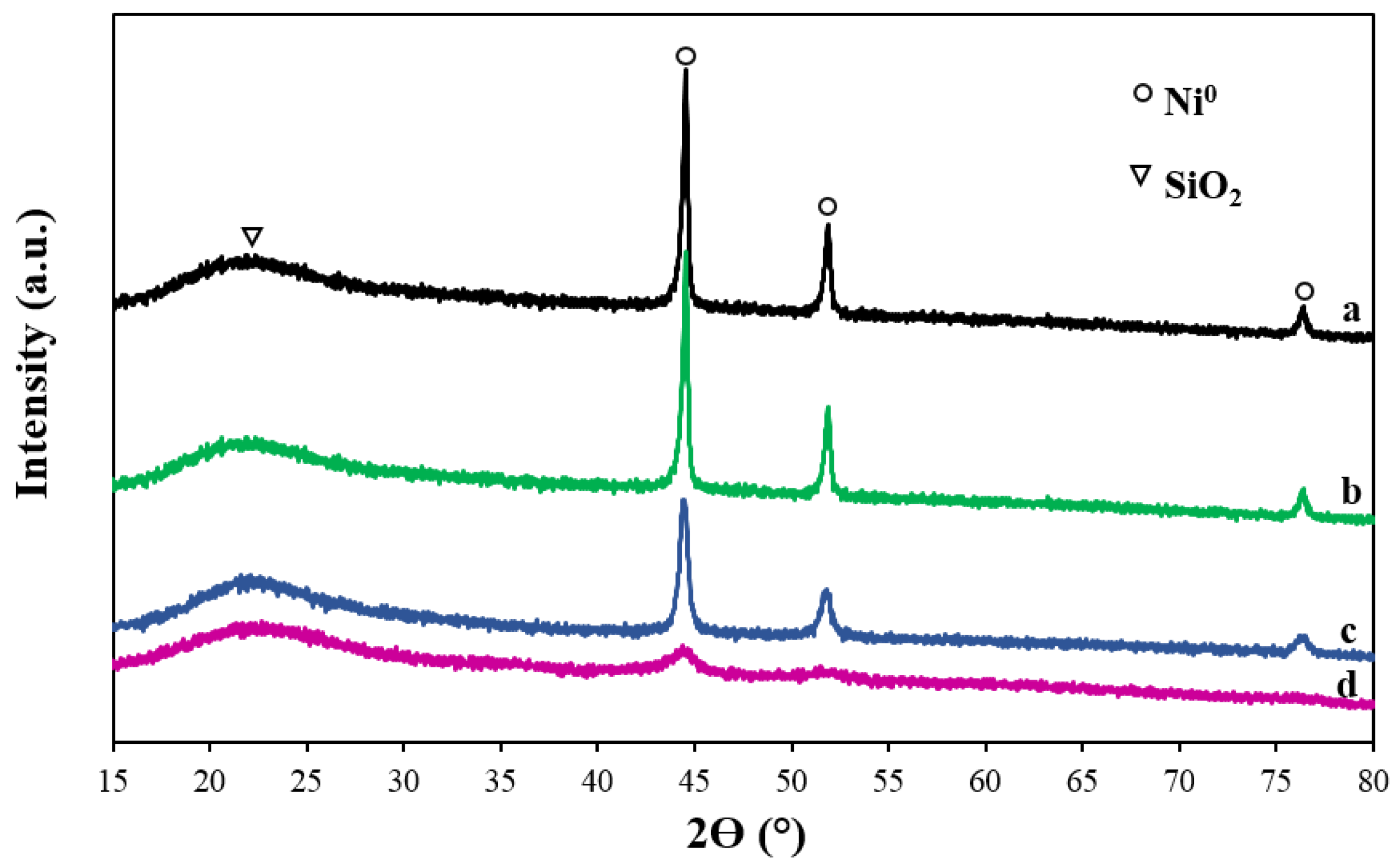
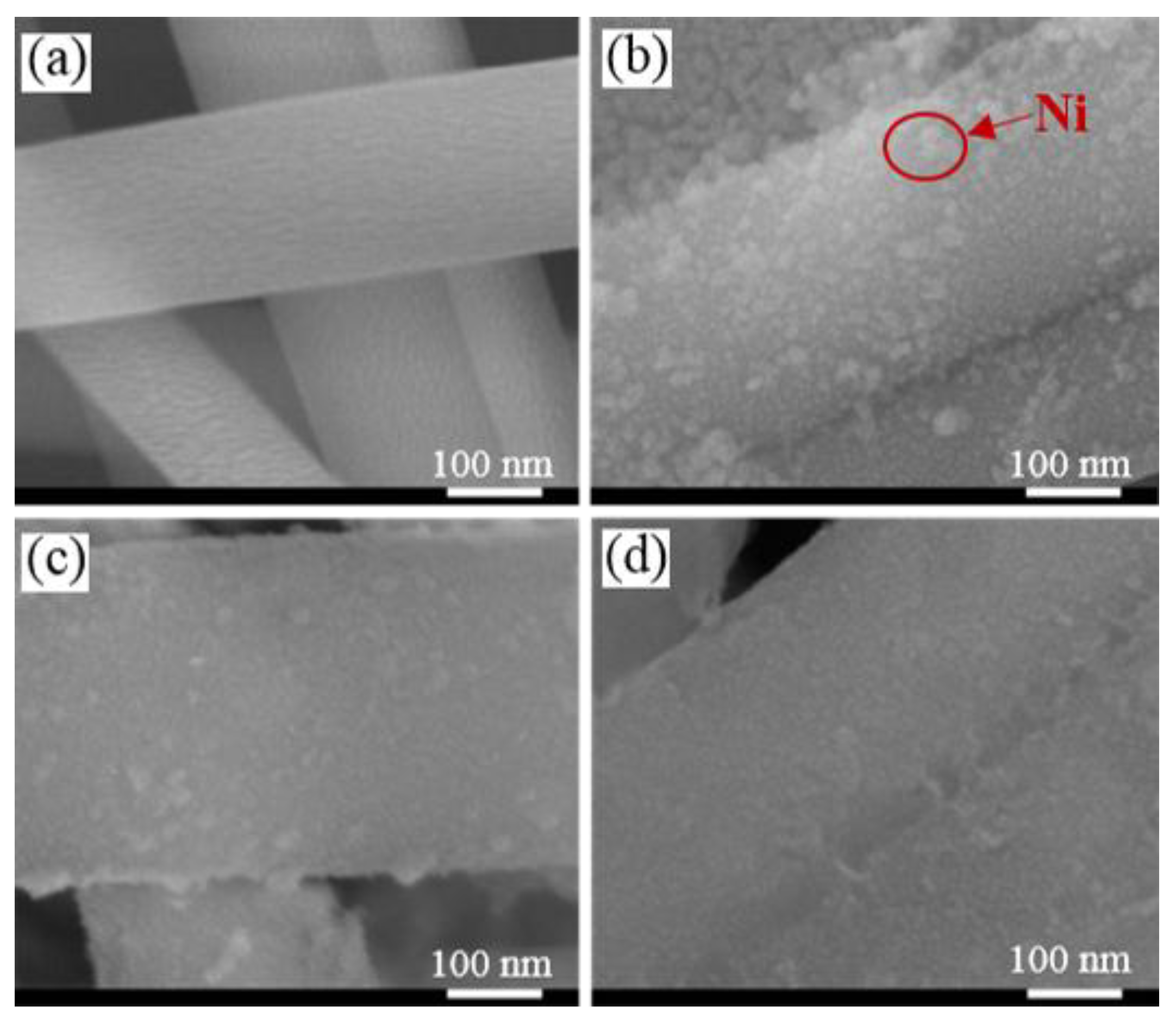
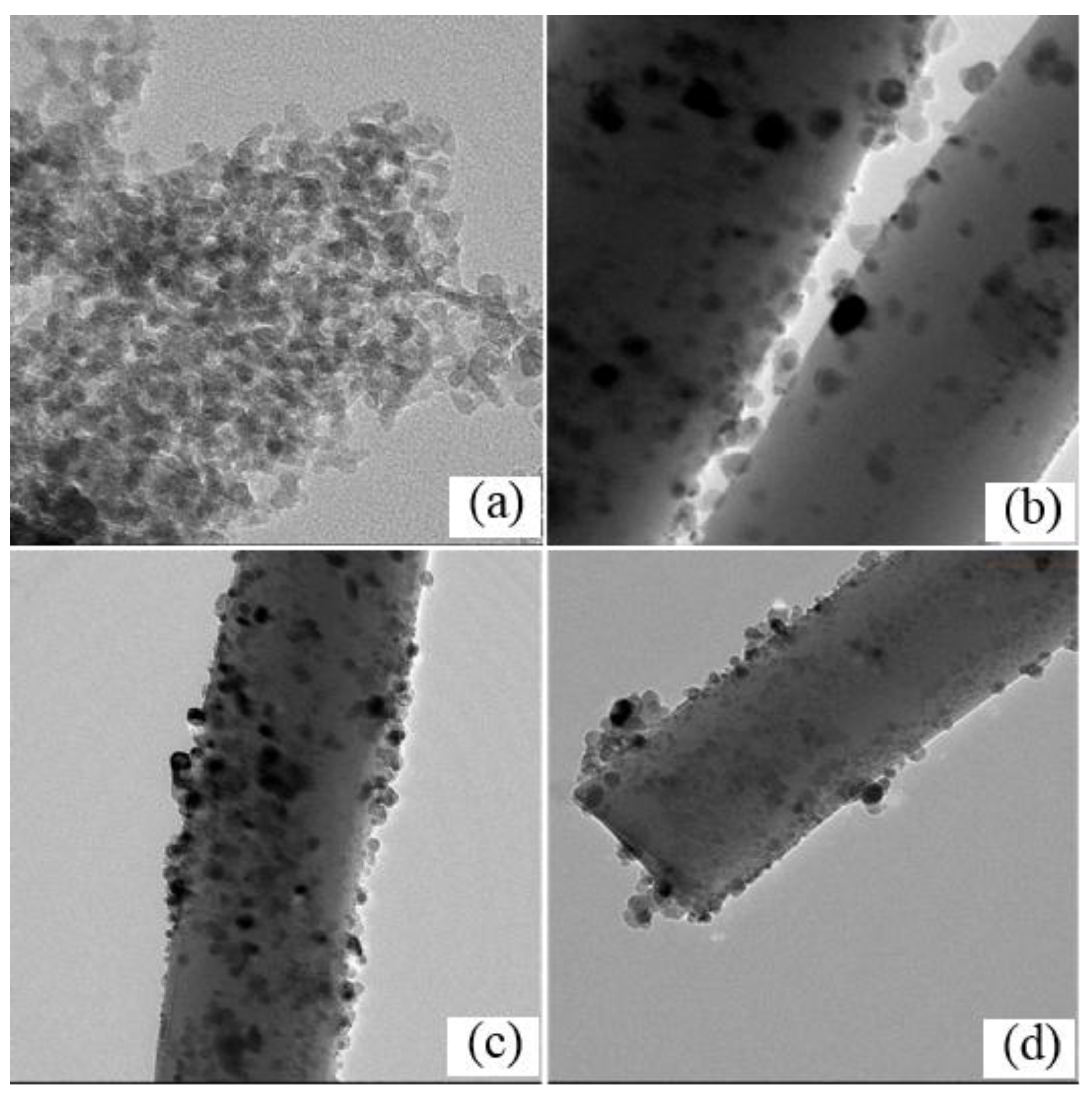
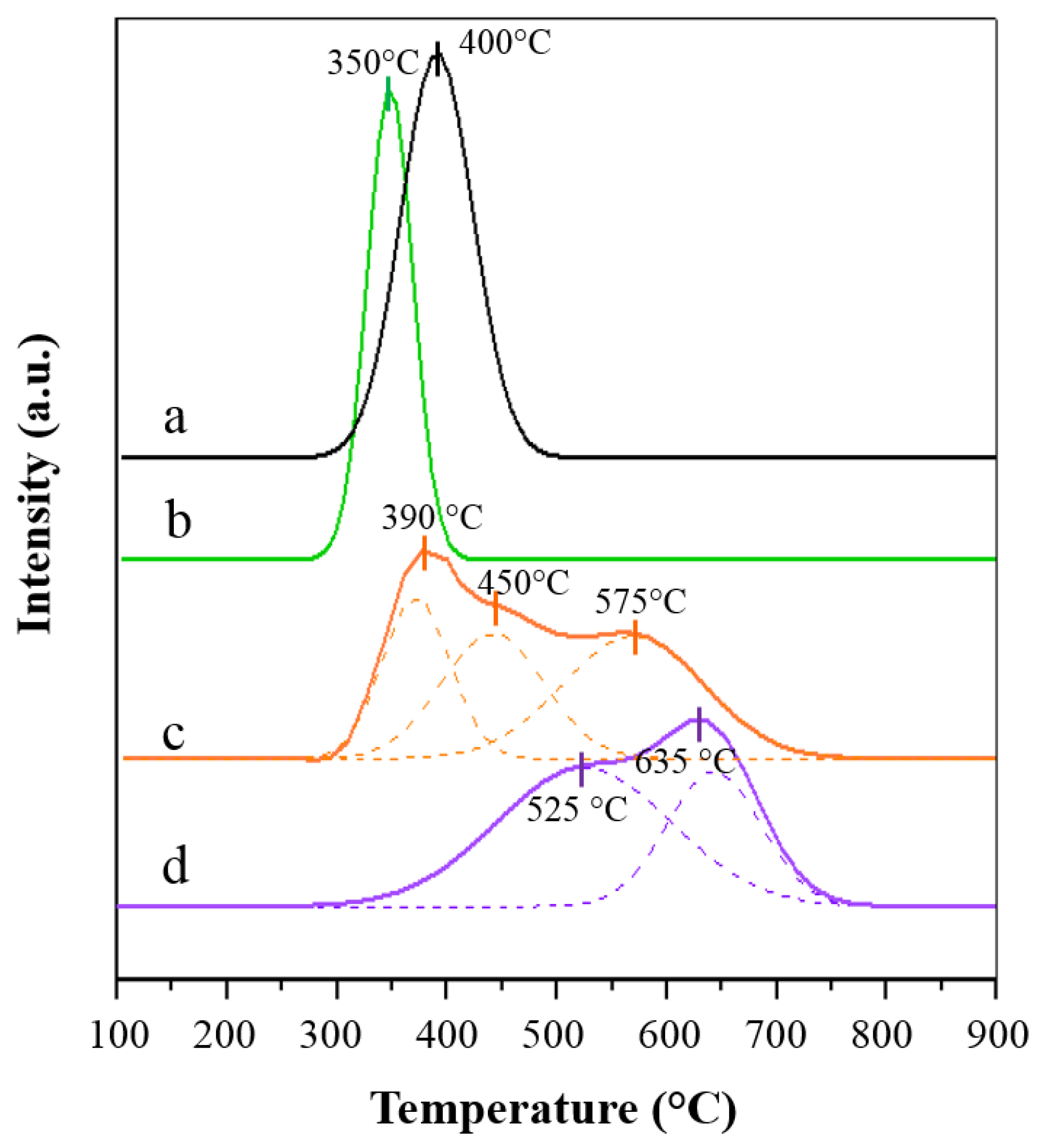
2.1. Characterization of the Catalysts

The actual contents of Ni measured by energy dispersive X-ray analysis (EDX) are shown in Table 1. It is evident from the results that the Ni loadings of samples except the Ni/SF-SEA sample were 11 wt.%, which was fairly similar to the theoretical value. The actual Ni content of the Ni/SF-SEA sample was 8 wt.%, which was a little lower than the theoretical composition because Ni was washed by water in the filtration step. It should be mentioned that some other additional techniques, such as inductively coupled plasma atomic emission spectroscopy (ICP) and X-ray fluorescence spectroscopy (XRF) would be required to ensure the true quantification of Ni.
The textual properties, including the SBET, VP and average pore diameter (DP) of the Ni-based catalyst and respective support, as well as the Ni content and NiO crystallite size are presented in Table 1. The SF support exhibited a markedly smaller SBET and VP than the SP support, due to its non-porous nature, while after adding Ni to the SF support by IM method, the SBET increased slightly from 5.9 to 9.9 m2/g, which was attributed to decorating of NiO on the SF surface. The different preparation methods had a signification effect on the textual properties of the Ni/SF catalysts. The surface of the Ni/SF catalyst prepared by the IM had a smaller SBET (9.9 m2/g) and VP (0.011 cm3/g) than that of catalysts prepared by the DP and SEA methods. In the case of the catalyst prepared by DP and SEA methods, the SBET increased significantly. The SBET of Ni/SF-DP and Ni/SF-SEA catalysts were 26.7 and 35.9 m2/g, respectively. Klaigaew et al. [21] have recently reported the effect of catalyst preparation method on the textual properties of catalyst. The results found that the catalysts prepared by the DP and SEA methods could promote higher dispersed metals on the supports which increased the SBET.
Figure 1 shows representative X-ray diffraction (XRD) patterns of the fresh catalysts. The broad diffraction peak appearing with an equivalent Bragg angle at 2θ = 22°, corresponded to amorphous silica (JCPDS file No. 86-0681). The diffraction peaks centered at 44.5° and 51.9°, respectively, and were assigned to the Ni phase [22]. The XRD crystal sizes of NiO and Ni are also shown in Table 1. The crystallite sizes of Ni and NiO in the Ni/SP-IM catalyst were 32 and 15, respectively, and in the Ni/SF-IM catalyst were 32 and 22, respectively. The metal sizes of Ni increased significantly after reduction which was probably due to sintering. The crystallite sizes of Ni and NiO in the Ni/SF-IM catalyst were larger than that of the Ni/SP-IM catalyst probably due to its lower surface area. However, the Ni and NiO crystallite sizes were clearly smaller when the catalysts were prepared via DP and SEA methods, implying the catalyst prepared via DP and SEA methods helped to decrease the catalyst particle sizes. The crystallite sizes of metal after reduction of the Ni/SF-DP and Ni/SF-SEA catalysts were almost unchanged implying that the Ni/SF-DP and Ni/SF-SEA catalysts gave an excellent sintering-resistance. The larger NiO crystallite size for the catalyst prepared by IM was probably due to the migration or accumulation of NiO species during thermal treatment, while the catalysts prepared by the DP method provided smaller metal particles because of the introduction of basic reagent to form metal compounds with a low solubility [20,21]. This can control nucleation of the active metal to occur only on the support and not in the bulk solution which led to the formation of small particles. In the case of the catalysts prepared by the SEA method, small NiO crystallite size could be achieved by a change in pH of the SF-support surface to contain hydroxyl groups, which act as adsorption sites for metal complexes and facilitate the deposition of a metal phase, forming small particles [19].
Figure 2 shows the morphology of the SF-support and fresh catalysts, as analyzed by FESEM, where the surface of the SF support was smooth with an average outer diameter of 171 nm. The NiO was found to disperse the surface of SF-support of the catalyst prepared by all three different methods. However, in the Ni/SF-IM catalyst, the NiO seemed to be aggregated and poorly dispersed. Some multiparticles of NiO, including small and large particle sizes, were observed in the Ni/SF-DP catalyst, while, in the Ni/SF-SEA catalyst, NiO were well dispersed and clearly smaller than in the Ni/SF-IM and Ni/SF-DP catalysts. These features likely contributed the SBET of the SF-supported catalysts. The well dispersed and small metal particles could result in increasing the SBET.
The transmission electron microscopy (TEM) micrographs of the fresh catalysts are presented in Figure 3, where the darker points are the metal particles and the lighter ones are the Si support. The spherical shaped NiO particles were observed on the Si support in all the catalysts. The TEM micrograph of the SF-supported Ni catalysts formed via the three different methods; the NiO particles were small and highly dispersed on the external surface of the SF-support, particularly in the Ni/SF-DP and Ni/SF-SEA catalysts. The estimated particle sizes of NiO obtained from the TEM images range from 7 to 20 nm, and are shown in Table 1. The average particle size of the catalysts was ranked as follows: Ni/SF-SEA < Ni/SF-DP < Ni/SP-IM < Ni/SF-IM. Thus, the NiO particle size of the catalyst prepared via SEA showed the smallest NiO particle size (7 nm). These results were in good agreement with the XRD results.
The Hydrogen temperature-programmed reduction (H2-TPR) profiles of the fresh catalysts are shown in Figure 4. In the Ni/SP-IM and Ni/SF-IM catalysts, only a single reduction peak was observed at 350 °C and 400 °C, respectively, corresponding to the reduction of NiO to Ni0. The reduction temperature of the Ni/SP-IM catalyst was higher than that for the Ni/SF-IM catalyst due to smaller NiO particle size. In the Ni/SF-DP catalyst, there were three reduction temperatures. The first reduction peak was assigned to the reduction of NiO with large particle sizes or those with a weak interaction with the support. The second and the third peaks were the reduction of NiO with either small metal particles or those with a strong interaction with the support [23]. As for the Ni/SF-SEA catalyst, there were two reduction peaks and both were shifted towards a higher temperature compared to the Ni/SF-IM and Ni/SF-DP catalysts. These were attributed to the fact that the active NiO particles in the Ni/SF-SEA catalyst were smaller and more highly dispersed [24]. The presence of the reduction peak at a higher temperature (above 500 °C) in the Ni/SF-DP and Ni/SF-SEA catalysts indicated that the interactions between the supported phase and the support were stronger compared to the catalyst prepared by the IM. Similar results have been obtained by Jiao et al. [19]; the reduction temperature of SEA prepared samples determined by TPR was significantly higher than that of impregnation prepared samples. Nakanishi et al. [25] compared the catalytic activities of the Co prepared using different preparation methods, such as impregnation, incipient wetness, physical mixing and precipitation methods and reported that cobalt interacted strongly with the support surface for the catalyst prepared by precipitation method. It should be mentioned that some other additional techniques, such as X-ray photoelectron spectroscopy (XPS), would be required to ensure the interactions of Ni metal and support. Additional information about the physico-chemical properties of Ni/SiO2 samples has been reported elsewhere [19,26].
The metal dispersion of the catalysts was measured using H2 chemisorption, with the results shown in Table 1. The catalyst prepared via IM showed the lowest Ni dispersion probably due to the migration or accumulation of Ni species during hydrothermal treatment, while the catalysts prepared by DP and SEA exhibited higher Ni dispersion. The maximum Ni dispersion was obtained with the Ni/SF-SEA catalyst, which was consistent with its smaller Ni particle size. These results indicated that the catalysts prepared via SEA and DP significantly enhanced the dispersion of Ni.
Overall, the results from the XRD, SEM, TEM, H2-TPR and H2 chemisorption analyses indicated that the catalysts prepared by the DP and SEA methods improved the dispersion of NiO as well as provided smaller metal particles compare to the Ni/SF-IM catalyst. The improvement of dispersion of NiO-species via SEA method can be attributed to the modification of the SF-support surface by changing pH before adding Ni solution to the support. Consequently, the hydroxyl group of the support would be deprotonated to negative charge which could attract Ni cations, which facilitated the formation of smaller NiO particles [19]. The DP method provided high metal dispersion via the formation of a metal hydroxide in the solution by the addition of an ammonia into the precursor solution. The metal hydroxide is low solubility and prefers nucleation on the support to the bulk solution [20].

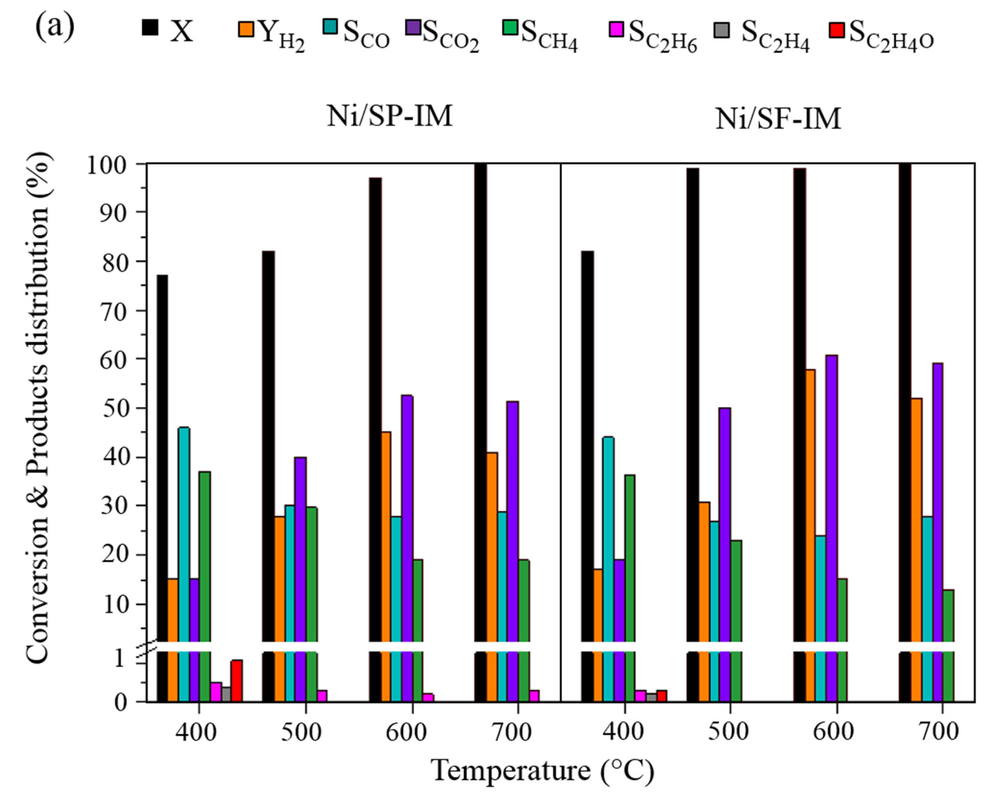
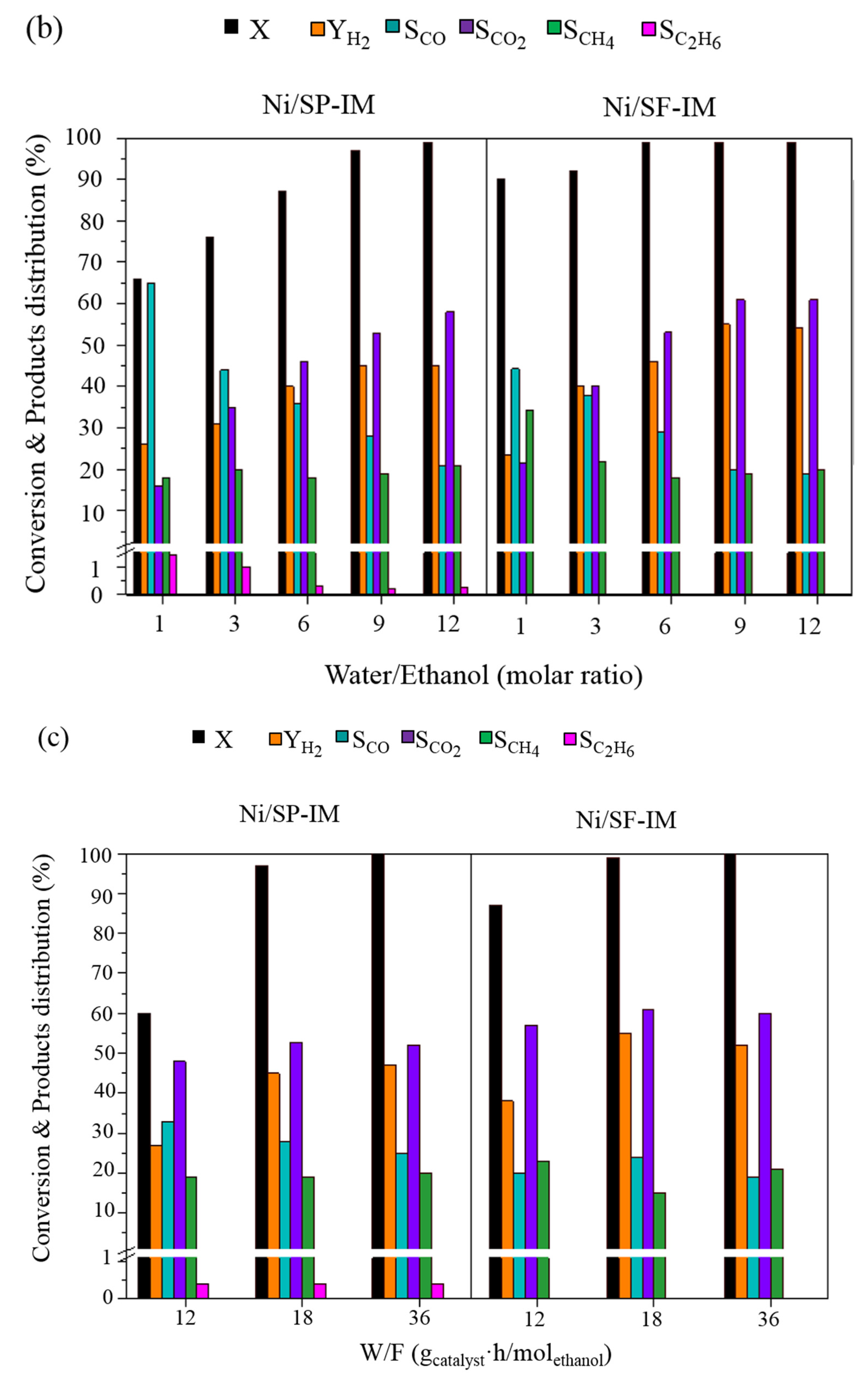
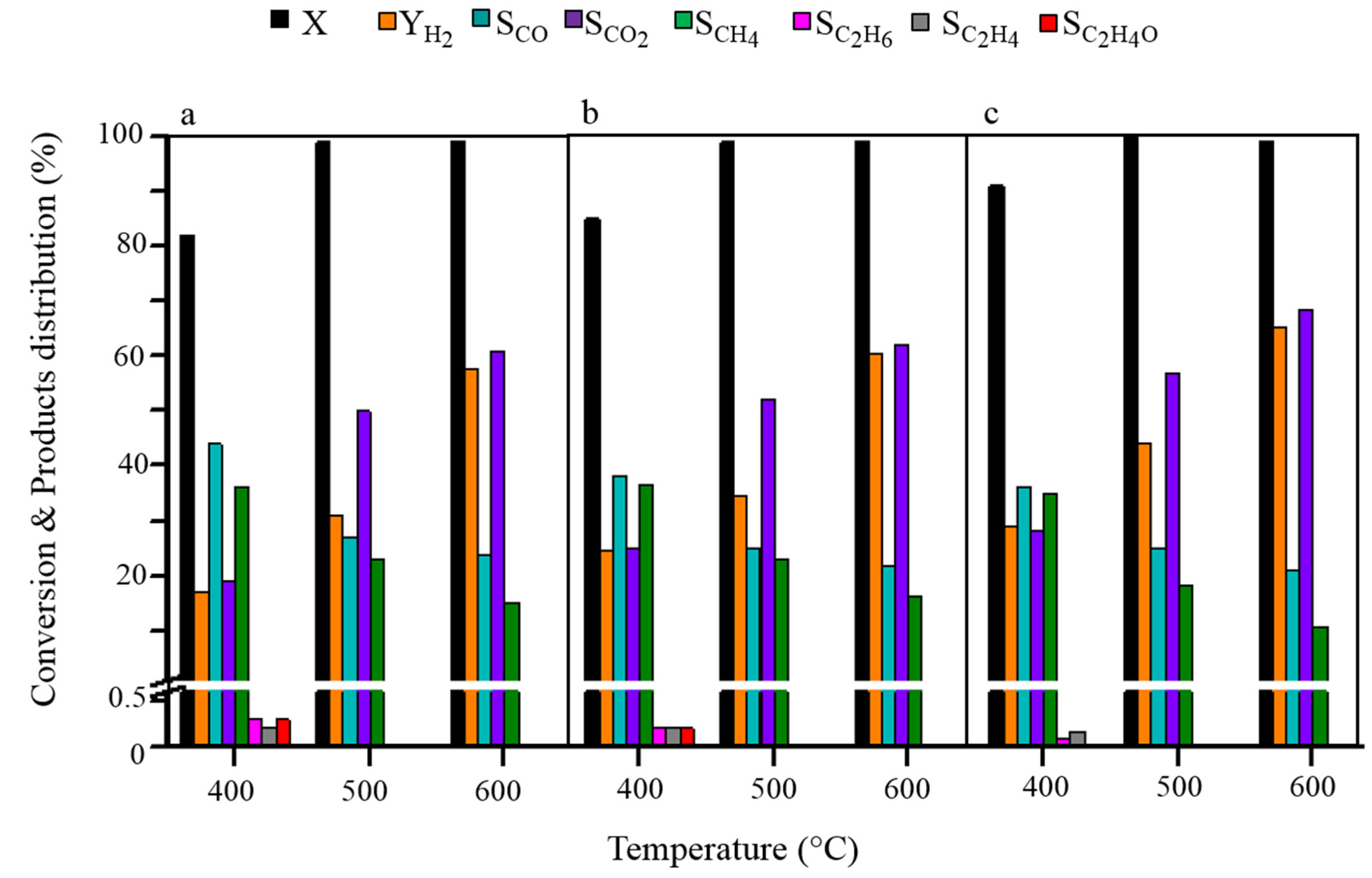
2.2. Catalytic Performance
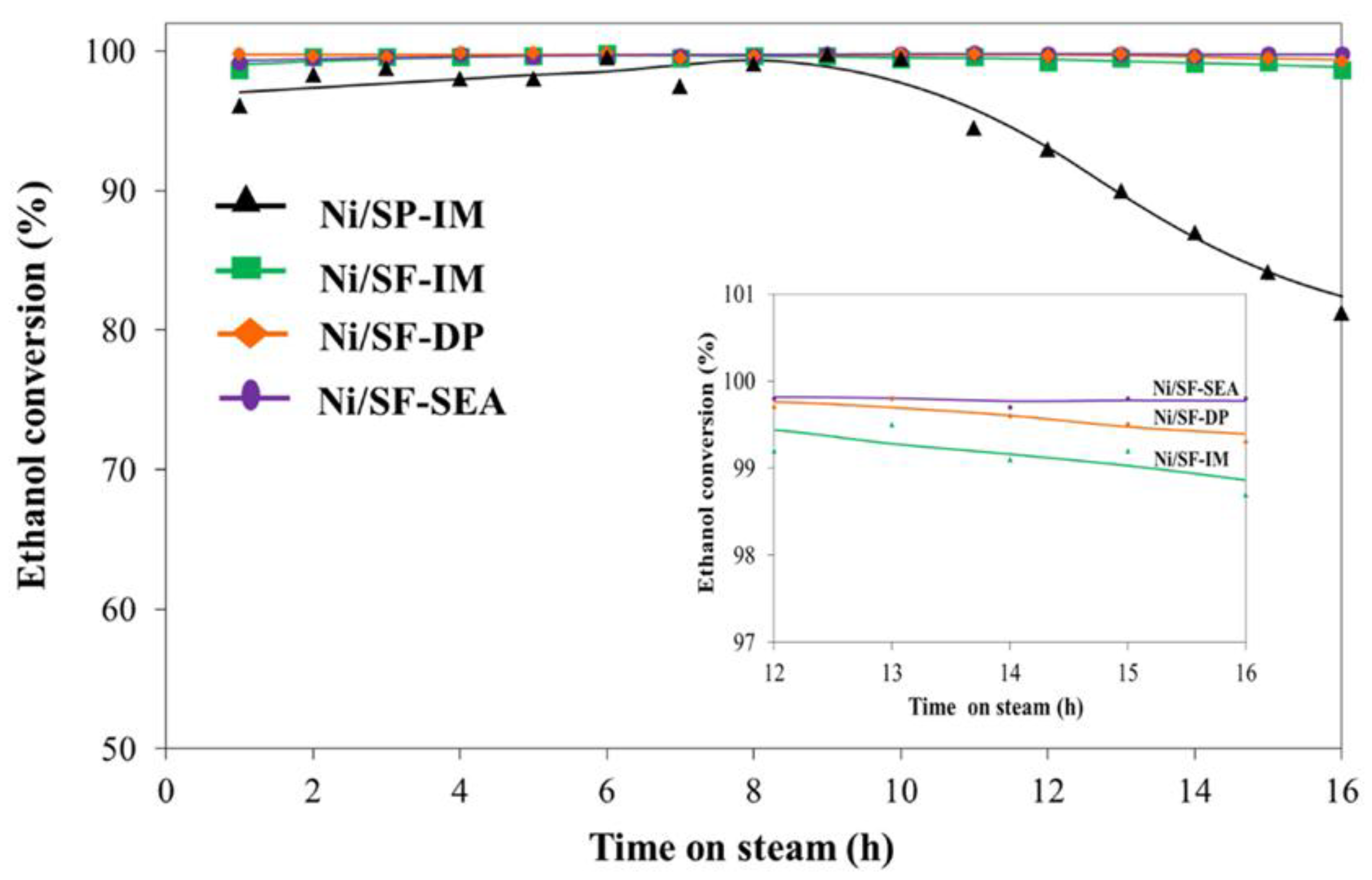
Figure 5a shows the ethanol conversion level and product selectivity of the SP- and SF-supported Ni catalysts at different reaction temperatures (400–700 °C) in the ESR. It can be clearly seen that the catalytic activity of both catalysts increased with increasing reaction temperature. The ethanol conversion level of the Ni/SF-IM catalyst was almost complete at temperature of 500 °C, while the ethanol conversion level of the Ni/SP-IM catalyst was accomplished at 700 °C. At lower temperature (400 °C), the C2 products (ethane, ethylene and acetaldehyde) were obtained, which was attributed to the low activity in C−C bond breaking of Ni. The formation of acetaldehyde was attributed to the dehydrogenation of ethanol (CH3CH2OH → CH3CHO + H2). According to the literatures [5,8,27], acetaldehyde was considered as an intermediate product in the ESR which can either decompose to CO and CH4 through C−C bond breaking or transform to ethane and water by the cleavage of the C−O bond of acetaldehyde and addition of hydrogen. As temperature increased, the traces of ethylene and acetaldehyde were no longer detected, whereas the trace of ethane was still detected for the Ni/SP-IM catalyst throughout the whole range temperature studied. The results suggested that the Ni/SF-IM catalyst had a higher C−C bond cleavage activity. This was attributed to the non-porous nature and open structure of the SF support, with the active Ni catalyst dispersed and exposed on the external surface which facilitated the reduction of NiO species to be active species. As evidenced by TPR analysis, the reduction of NiO species in the Ni/SF-IM catalyst was easier compared to in the Ni/SP-IM catalyst, implying the Ni/SF-IM catalyst had higher activity [13,28]. Increasing temperature from 400 to 600 °C, the concentration of CH4 dropped gradually, while the H2 yield and CO2 selectivity increased. The activity of Ni in cleaving C−C bond was enhanced, and so facilitated steam reforming of ethanol and acetaldehyde. The steam reforming of acetaldehyde also explained the increase in H2 yield as it is thermodynamically favored at a higher temperature. The maximum H2 yield for the Ni/SF-IM and Ni/SP-IM catalysts were 55% and 47%, respectively. The high H2 yield and CO2 selectivity of the Ni/SF-IM catalyst indicated that it facilitated the CH4 steam reforming and water-gas shift (WGS) reactions. However, when the ESR reaction temperature was increased from 600 to 700 °C, there was a slight decrease in the amount of H2 and CO2, while the selectivity of CO increased slightly. The decrease in the H2 yield likely reflects that the WGS reaction is negligible at temperatures above 600 °C because of the exothermic nature of the WGS reaction. Nevertheless, the reverse WGS (H2 + CO2 → H2O + CO) became favorable, leading to the increased CO selectivity and decreased CO2 selectivity [29].
The effect of the steam/ethanol (S/E) molar ratio on the ethanol conversion level and product distribution was investigated over a range of 1–12 at 600 °C and a space time of 18 gcat.·h/mol[EtOH], with the results shown in Figure 5b. The ethanol conversion level with the Ni/SF-IM and Ni/SP-IM catalysts increased as the S/E molar ratio increased to 9, while the H2 yield and CO2 selectivity also increased progressively, and the CO and CH4 selectivity decreased gradually. That a higher water content increased the ethanol conversion level and H2 yield was attributed to it favoring the ethanol and methane steam reforming and WGS reactions [6]. Figure 5b, observing that the values of H2 yield, EtOH conversion and selectivities were basically the same when using water/ethanol 9 and 12. It could be deduced that values of water/ethanol higher than 9 were not needed to enhance the ESR. For economic perspective, operation at much higher water content could increase operating energy costs for evaporation of water [30]. Furthermore, it could be observed that in the products of the tests with Ni/SP-IM there is, even in a small percentage, some C2H6 decreasing with higher values of water/ethanol; for Ni/SF-IM instead, C2 compounds were not detected at all. This fact could also be attributed to the higher C-C bond cleavage activity of the Ni/SF-IM catalyst, primarily due to its non-porous nature and open structure of the SF support. As observed by SEM and TEM, the metal species were dispersed on the external surface which could be easily accessible to the reactants. Comparison between the Ni/SP-IM and Ni/SF-IM catalysts, revealed that the ethanol conversion level with the Ni/SF-IM catalyst reached completion faster than that with the Ni/SP-IM catalyst as its reduction was easier resulting in higher activity compared to the Ni/SP-IM catalyst.
The effects of space time (W/F) on the ethanol conversion level and products distribution were investigated over a space time range from 12 to 36 gcat.·h/mol[EtOH] at 600 °C and S/E molar ratio of 9. As shown in Figure 5c, ethanol conversion level obtained with the Ni/SP-IM and Ni/SF-IM catalysts increased as the space time increased. The H2 yield also tended to increase as the space time increased. This phenomenon can be explained in terms of the contact time between the reactants and active sites of the catalyst. At a lower space time, the contact time between the reactants and the active sites of the catalyst was too short, giving a low ethanol conversion level and H2 yield. At a higher space time, the ethanol molecules have sufficient contact time with the catalyst for cleavage of their C−C and O−H bonds, resulting in a high ethanol conversion level and H2 yield [29]. However, the ethanol conversion level and selectivity of all products did not significantly change when the space time was further increased from 18 to 36 gcat.·h/mol[EtOH]. Thus, the optimum conditions for ESR was selected as 600 °C, a S/E molar ratio of 9 and a W/F 18 gcat.·h/mol[EtOH]. The maximum H2 yield obtained with the Ni/SP-IM and Ni/SF-IM catalysts were 47 and 55%, respectively.
The effect of the Ni-based catalyst preparation methods on the ethanol conversion level with various reaction temperature (S/E molar ratio of 9 and W/F 18 gcat.·h/mol[EtOH]) is shown in Figure 6. The ethanol conversion levels obtained with the Ni/SF-IM, Ni/SF-DP and Ni/SF-SEA catalysts at 400 °C were about 82%, 86% and 91%, respectively. The acetaldehyde selectivity with the Ni/SF-IM and Ni/SF-DP catalysts was 0.2% while it was not detected with the Ni/SF-SEA catalyst. Thus, the Ni/SF-SEA catalyst had a higher C−C cleavage ability than the other two catalysts. As the ESR reaction temperature increased up to 500 °C, the ethanol conversion level reached almost 100% and no C2 products were detected with all the catalysts. The CO2 selectivity and H2 yield increased while the CO and CH4 selectivities decreased due to the enhanced WGS and methane steam reforming reactions, with an increased H2 yield (>60%) being obtained with the Ni/SF-DP and Ni/SF-SEA catalysts. According to these results, the Ni/SF-SEA catalyst exhibited a higher catalytic activity and produced a higher H2 yield than those catalysts prepared by IM and DP methods which is attributed to its high surface area, smaller particle sized and better dispersed Ni particles on the surface of the SF support, resulting in excellent capability to access nickel active sites.
Table 2 summarizes the C balance (%) of the catalysts from the ESR at 600 °C, W/F of 18 gcat.·h/mol[EtOH] and a S/E molar ratio of 9. The products consisted of gases and solid carbon. The solid carbon was determined by TGA analysis. The solid carbon can contribute to the deactivation of catalysts in steam reforming by decreasing available activate sites of the catalyst and accessibility to the reactants. As observed in Table 2, the results indicated that the SF-catalysts produced lower solid carbon than the Ni/SP-IM catalyst. In comparison to the different Ni/SF preparation method, the Ni/SF-DP and Ni/SF-SEA catalysts exhibited lower solid carbon but produced higher gas products. As evidenced by the TPR results, the Ni/SF-DP and Ni/SF-SEA catalysts showed the strong interaction between metal and support that could effectively reduce carbon deposition during the reaction [28].
Table 3 shows the comparison of H2 yield from the ethanol steam reforming over Ni-based catalysts in this study with H2 yield in the literature reviews. The table shows that H2 yield over the supported-Ni catalyst prepared by the SEA method was higher than that over the supported-Ni catalysts obtained using the impregnation method.

2.3. Stability Test

The stability of the Ni/SP-IM, Ni/SF-IM, Ni/SF-DP and Ni/SF-SEA catalysts were evaluated in the ESR over 16 h at 600 °C, W/F of 18 gcat.·h/mol[EtOH] and a S/E molar ratio of 9, with the results shown in Figure 7. The ethanol conversion level obtained with the Ni/SF-IM, Ni/SF-DP and Ni/SF-SEA catalysts reached almost 100% within 1 h of reaction and remained almost constant throughout the 16 h time on stream. In contrast, the initial activity for the Ni/SP-IM catalyst was lower compared to other catalysts. The maximum ethanol conversion level was 95% at 6 h of reaction and then it dropped gradually after 8 h of reaction probably due to the catalyst deactivation. Additionally, as shown in the stability test (Figure 7 inset), the Ni/SF-SEA catalyst exhibited much higher stability as compared to other catalysts. The main cause of catalyst deactivation in the ESR is reported to be the formation of carbon and sintering on the catalyst [23], and this was evaluated and discussed in section characterization of the spent catalysts.

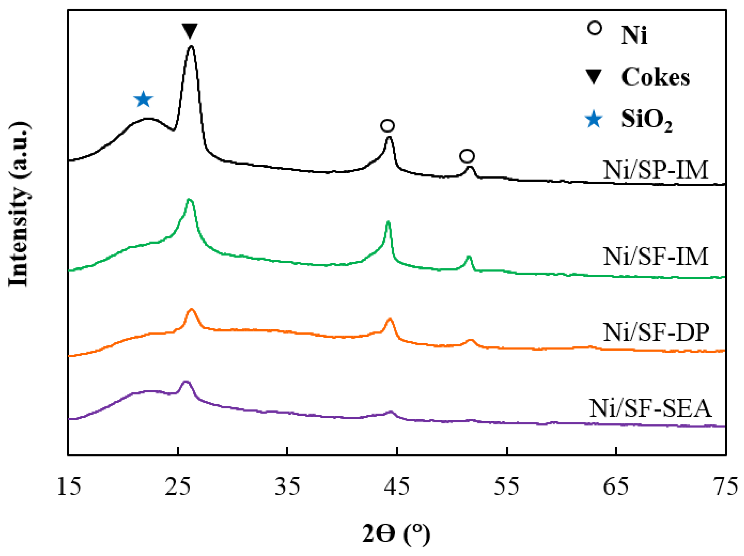
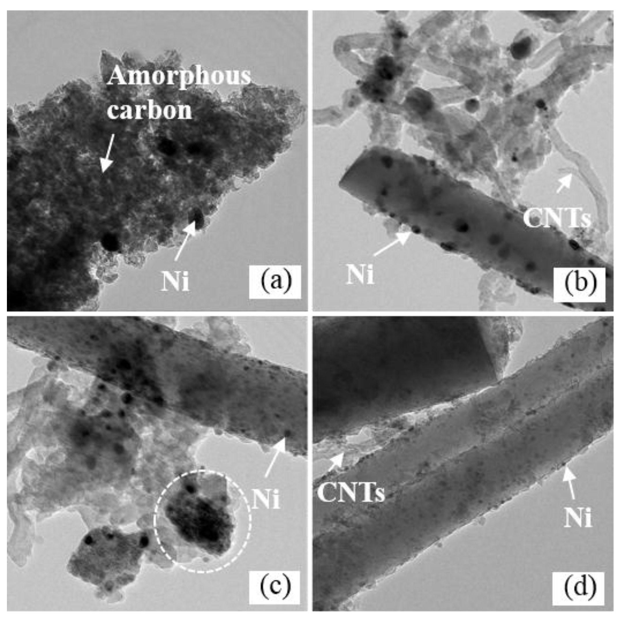
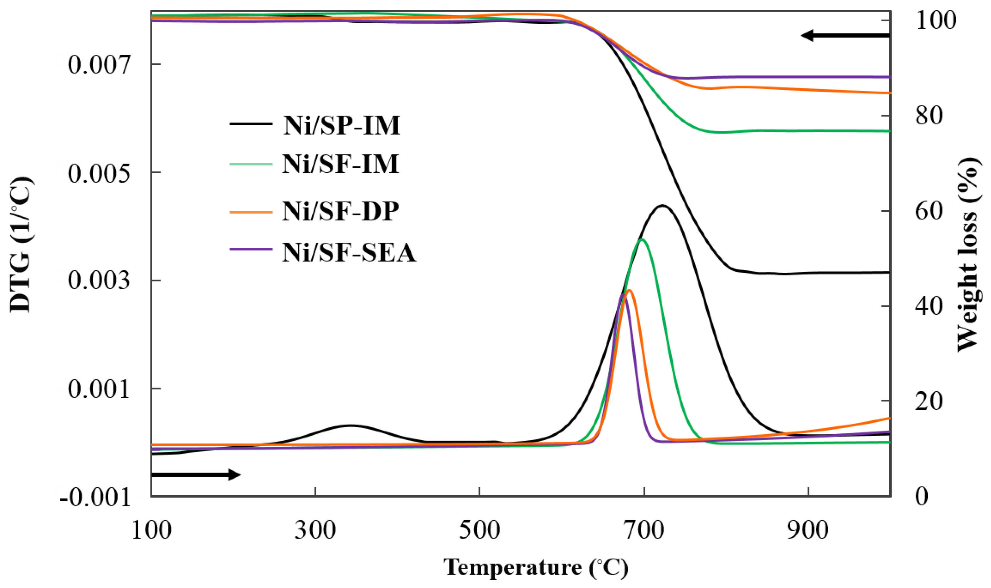
Characterization of the Spent Catalysts

In order to understand the cause of catalyst deactivation leading to the loss of activity, XRD, TEM and thermogravimetry and differential thermogravimetry (TG/DTG) analyses were performed to examine the spent catalysts after a 16 h ESR reaction (stability test).
The XRD patterns of the spent catalysts are presented in Figure 8. The diffraction peak at a 2θ of 26° was assigned to the formation of carbon on the surface of the catalysts. The intensity of the carbon peak for the SP-supported catalyst was higher than that for the SF-supported catalyst, suggesting that the carbon deposition was much more significant on the SP catalyst [34]. The peaks located at a 2θ of 44.5° and 51.9° for all spent catalysts were assigned to metallic Ni [32]. The Ni crystallite sizes for all the spent catalysts as calculated from the Scherrer’s equation, are presented in Table 2. The Ni crystallite sizes in all the catalysts increased after the ESR reaction due to the sintering of the metal. The Ni crystallite sizes were ranked in the order: Ni/SF-IM (37 nm) > Ni/SP-IM (36 nm) > Ni/SF-DP (16 nm) > Ni/SF-SEA (8 nm). The results suggested that the catalyst prepared by the DP and SEA methods showed less aggregation of the active Ni during steam reforming because of the strong interaction between the metal and support.
Carbon deposition on a catalyst generally happens in a steam reforming reaction via methane decomposition, Boudouard reaction and ethylene polymerization. According to Ma et al. [23], large metal particles were favorable for the Boudouard reaction and methane decomposition that accounted for the large amount of accumulated carbon. The high nickel dispersion and strong metal−support interaction effectively suppressed metal aggregation which could help to reduce carbon deposition, therefore enhancing the stability of the nickel catalyst. Zhang et al. [35] reported the preparation methods had a significant effect on the catalytic activity and stability of Ni catalyst. The catalyst obtained via ammonia evaporation method had stronger metal−support interaction and better nickel dispersion compared to that obtained via conventional impregnation. Naeem et al. [17] have found a severe deactivation on the catalyst from carbon deposition. Encapsulation carbon on metal particles significantly decreased catalytic activity but filamentous carbon with metal particles being on the top of the carbon could be still active and exposed by reactants. TEM micrographs of the spent catalysts are shown in Figure 9; the Ni/SP-IM catalyst showed a significant amount of amorphous carbon, which seemed to widely cover the active sites of the catalyst. This led to closed active sites on the catalyst and, therefore, is likely to be the reason for the reduced ethanol conversion level after 10 h time-on-stream. On the other hand, the carbon deposition in the form of filaments was clearly observed on the SF-supported catalysts and large Ni particles were observed at the top of the filaments where they could be accessible by the reactants. Therefore, it was the reason why the SF-supported catalysts showed better catalytic stability. As shown in Table 2, the metal particle sizes of the catalysts increased after the steam reforming reaction. It was clearly observed that the particle size for Ni/SF-IM catalyst increased significantly compared to those for the Ni/SF-DP and Ni/SF-SEA catalysts. Thus, the catalysts prepared by the DP and SEA methods effectively suppressed sintering, which was attributed to the strong interaction between the active phase and support, which then maintained a good dispersion of the active species in the catalysts during the ESR; the good interaction of Ni with the support also helped the reduction of the carbon deposition effect, thus giving higher performances and maintaining a better stability in the ESR tests.
The TG/DTG curves of the spent catalysts are presented in Figure 10. The Ni/SP-IM catalyst showed two decomposition peaks at around 300–450 °C and 600–850 °C, with the first assigned to the decomposition of amorphous carbon and the second assigned to the decomposition of graphitic carbon [36,37]. In contrast, only one decomposition peak (500–700 °C) was observed on the SF-supported Ni catalysts, which was attributed to the decomposition of graphitic carbon. The spent Ni/SP-IM catalyst showed a higher carbon deposit than the spent Ni/SF-IM catalyst. It has been reported that deposition of carbon on porous catalysts occurred inside the pore, and it is difficult to remove by gasification via the reaction of water with the carbon deposit, resulting in a higher accumulation of carbon deposits [28,32]. In contrast, the SF-supported Ni catalysts had no pores and the active sites were dispersed on the external surface of the SF, which could easily contact with the reactants. Therefore, carbon deposition on the Ni/SF-IM catalyst could easily be removed by gasification via a reaction of the carbon deposit with water, resulting in a lower amount of carbon deposit. Overall, the SF-supported catalysts showed excellent coking resistance. Comparison of the different Ni/SF preparation methods, revealed that the amount of carbon deposition on the Ni/SF-DP and Ni/SF-SEA catalysts were lower than the Ni/SF-IM catalyst, reflecting the stronger interaction between the Ni and SFs that effectively prevented the carbon deposition on the catalysts during the steam reforming reaction [38]. The weight loss percentages of the catalysts were in the sequence: Ni/SP-IM >Ni/SF-IM >Ni/SF-DP > Ni/SF-SEA.

3. Experimental

3.1. Catalyst Preparation

The SF used as a catalyst support in this work was synthesized through the combination of sol-gel and electrospinning techniques [39] to give 160–170 nm diameter SF. The SP (Fuji Silysia Chemical Ltd., 1D silica support 20–40 mesh) was used as a comparative support for the Ni in the ESR. The Ni/SF and Ni/SP catalysts were prepared by the IM with a fixed Ni loading for all catalysts of 10 wt.%. Subsequently, to compare the effect of the preparation method, the Ni/SF catalysts were prepared in a similar way except using the IM, DP and SEA methods as detailed below.
(a) IM
Nickel nitrate hexahydrate (Ni(NO3)2•6H2O; Merck, Darmstadt, Germany) as the Ni precursor was dissolved in deionized water (DW). This solution was then added dropwise onto the SF or SP support and after impregnation the resultant catalyst was dried at 110 °C overnight and then calcined at 500 °C for 2 h. The catalysts prepared by the IM from SP and SF supports were named as Ni/SP-IM and Ni/SF-IM, respectively.
(b) DP
In the DP method, Ni(NO3)2•6H2O was dissolved in DW and ammonia solution (28 wt.%) was slowly added until the pH of the solution reached 9. The SFs were then added to this solution, kept for 12 h at room temperature and then filtered and washed with DW until the pH was close to 7. The obtained catalyst was dried at 110 °C for 12 h and then calcined at 500 °C for 2 h to yield the Ni/SF-DP catalyst.
(c) SEA
The SF, used as the catalyst support, was added to DW and adjusted to pH 12 using ammonia solution [19]. The Ni precursor, Ni(NO3)2•6H2O, was dissolved in DW and was added into the above SF suspension. The obtained suspension was filtered and washed in DW until pH 7 before being dried at 110 °C for 12 h and calcined at 500 °C for 2 h to yield the Ni/SF-SEA catalyst3.2. Characterization of the catalysts

3.2. Characterization of the Catalysts

The specific surface area (SBET) and pore volume (VP) of each catalyst were measured from the nitrogen (N2) adsorption-desorption isotherms using a Micromeritics ASAP 2020 instrument. Energy dispersive X-ray analysis (EDX), performed on a Rayny EDX-700 instrument, was used to determine the actual amount of the Ni (as NiO) on each catalyst. Hydrogen temperature-programmed reduction (H2-TPR) was conducted by using a Micromeristics TPD/TPR 2920 system. The reactor temperature was heated up to 900 °C at a heating rate of 10 °C/min. The determination of the crystal structure was analyzed by X-ray diffraction (XRD) in a Bruker D8 Advance equipped with Cu-Kα radiation with the radiation source CuKα, operating in the 2θ angle range of 5-80° with a resolution of 0.02°. The crystal size of the catalyst was calculated from Scherrer’s equation using 2θ = 42.8° for NiO and 44.5° for Ni. The active metal surface of the catalyst was determined by H2 chemisorption using BELCAT-B (BEL Japan, Inc.) instruments. The samples were reduced at 700 °C for 1 h under 10%H2/Ar mixed gas flow. After that, the temperature was cooled down to room temperature and the chemisorption was carried out by pulsing of a 10% H2/Ar. The active surface area of Ni was calculated from the volume of H2 adsorbed by assuming the stoichiometric ratio Hadsorbed/Nisurface of 1 and a density of active sites on the surface of 1.54 × 10⁻¹⁹ atoms/m2 [23]. Field emission scanning electron microscopy (FESEM) were performed with a JSM-7610F model microscope to obtain images of the morphology of all catalysts, along with transmission electron microscopy (TEM) using a FEI Tecnai G2 20 TEM/STEM/EDX to examine the catalyst particle sizes. The amount of carbon deposition on the surface of the catalysts was determined by thermogravimetric analysis (TGA) with a TG/DTG 1 (Mettler Toledo) instrument under oxygen atmospheres at a heating rate of 5 °C min−1 from room temperature to 900 °C.

3.3. Catalyst Performance in the ESR

The performance of each catalyst in the ESR was evaluated in a fixed-bed reactor with 0.2 g of catalyst. Prior to the ESR operation, the catalysts were reduced in situ at 700 °C in a flow of 1:8 (v/v) H2:N2 at 40 mL/min for 1 h. The desired ratio of water: Ethanol was then fed into the evaporator (150 °C) using a HPLC pump along with a N2 flow at 20 mL/min to help conduct the steam into the reactor. The effects of the reaction temperature (400, 500, 600 and 700 °C), S/C molar ratio (1, 3, 6, 9, and 12) and W/F (12, 18 and 36 gcat.·h/mol[EtOH]) on the ethanol conversion level and gas production were studied. A new fresh catalyst was used at each condition and the reaction time was 6 h. The gaseous products obtained at the outlet of the reactor were analyzed on-line with gas chromatography (GC, Shimadzu GC-14B). A thermal conductivity detector (TCD) with a TDX-01 column was used for H2, CO2, CH4, and CO. The other one is a flame ionization detector (FID) with a Porapak-Q column for possible organic species including C2H4, C2H6, CH3CHO, and CH3COCH3. The unreacted ethanol was analyzed offline by FID.
The ethanol conversion level (XEtOH), the yield of H2 (YH2) and the products distribution of the carbon containing gas products (CH4, CO, CO2, C2H4, C2H6, CH3CHO and CH3COCH3) were determined from [8]:
XEtOH (%) = (EtOH, in – EtOH, out)/ (EtOH, out) × 100,
YH2 (%) = (moles H2 produced / (6 × moles EtOH converted)) × 100
Si (%) = (mole of gaseous product i) / (mole all gaseous products)

4. Conclusions

The catalytic activity of SP- and SF-supported Ni catalysts in the ESR reaction were evaluated at various conditions. The optimum conditions for a high yield of H2 was a reaction temperature of 600 °C, S/E molar ratio of 9 and a W/F of 18 gcat.·h/mol[EtOH]. The SF-supported Ni catalysts exhibited higher activity and stability than the SP-supported ones. The maximum H2 yield produced from the Ni/SF-IM catalyst was 55%, while that from the Ni/SP-IM catalyst was 47% under the same conditions. The effect of different preparation methods for the Ni/SF catalyst in the ESR was also investigated. The catalysts were prepared by IM, DP and SEA methods, and the Ni/SF-SEA catalyst was found to exhibit the highest ESR catalytic activity in terms of giving the highest H2 yield of 65%. The SEA method resulted in better control of the particle size of the Ni phase, while strong interactions between the Ni phase and support could prevent aggregation of the active metal particles and maintain their dispersion on the support during the ESR; the good interaction of Ni with the support also helped the reduction of the carbon deposition effect, thus giving higher performances and maintaining a better stability in the ESR tests.

Author Contributions

S.M., N.P and P.R. conceived and designed the experiments; S.M. and N.P. performed the experiments; analyzed the data; C.S. contributed analysis tool; P.R., S.M., N.P. and P.N. wrote the paper; all authors discussed the results and commented on the manuscript.

Acknowledgments

The authors are very grateful to a Center of Excellence on Petrochemical and Materials Technology and Overseas Academic Presentation Scholarship for Graduate Students, Graduate School, Chulalongkorn University for financial support.

Conflicts of Interest

The authors declare no conflict of interest.

References

  1. Benito, M.; Sanz, J.L.; Isabel, R.; Padilla, R.; Arjona, R.; Daza, L. Bio-Ethanol Steam Reforming: Insights on the Mechanism for Hydrogen Production. J. Power Sources 2005, 151, 11–17. [Google Scholar] [CrossRef]
  2. Contrerasa, J.L.; Salmones, J.; Colín-Luna, J.A.; Nuño, L.; Quintana, B.; Córdova, I.; Zeifert, B.; Tapia, C.; Fuentes, G.A. Catalysts for H2 production using the ethanol steam reforming (a review). Int. J. Hydrogen Energy 2014, 39, 18835–18853. [Google Scholar] [CrossRef]
  3. Carvalho, F.L.S.; Asencios, Y.J.O.; Bellido, J.D.A.; Assaf, E.M. Bio-ethanol steam reforming for hydrogen production over Co3O4/CeO2 catalysts synthesized by one-step polymerization method. Fuel Process. Technol. 2016, 142, 182–191. [Google Scholar] [CrossRef]
  4. Bej, B.; Pradhan, N.C.; Neogi, S. Production of hydrogen by steam reforming of ethanol over alumina supported nano-NiO/SiO2 catalyst. Catal. Today 2014, 237, 80–88. [Google Scholar] [CrossRef]
  5. Mattos, L.V.; Jacobs, G.; Davis, B.H.; Noronha, F.B. Production of hydrogen from ethanol: Review of reaction mechanism and catalyst deactivation. Chem. Rev. 2012, 112, 4094–4123. [Google Scholar] [CrossRef] [PubMed]
  6. Zhang, L.; Li, W.; Liu, J.; Guo, C.; Wang, Y.; Zhang, J. Ethanol steam reforming reactions over Al2O3.SiO2-supported Ni–La catalysts. Fuel 2009, 88, 511–518. [Google Scholar] [CrossRef]
  7. Vincenzo, P.; Concetta, R.; Eugenio, M.; Antonio, R. Renewable Hydrogen from Ethanol Reforming over CeO2-SiO2 Based Catalysts. Catalysts 2017, 7, 226. [Google Scholar] [CrossRef]
  8. Vicente, J.; Ereña, J.; Montero, C.; Azkoiti, M.J.; Bilbao, J.; Gayubo, A.G. Reaction pathway for ethanol steam reforming on a Ni/SiO2 catalyst including coke formation. Int. J. Hydrogen Energy 2014, 39, 18820–18834. [Google Scholar] [CrossRef]
  9. Cerritos, R.C.; Ramírez, R.F.; Alvarado, A.F.A.; Rosales, J.M.M.; García, T.V.; Esquivel, I.R.G. Steam reforming of ethanol over Ni/Al2O3-La2O3 catalysts synthesized by sol-gel. Ind. Eng. Chem. Res. 2011, 50, 2576–2584. [Google Scholar] [CrossRef]
  10. Sadeghzadeh, S.M. Ionic liquid immobilized onto fibrous nano-silica: A highly active and reusable catalyst for the synthesis of quinazoline-2,4(1 H,3 H)-diones. Catal. Commun. 2015, 72, 91–96. [Google Scholar] [CrossRef]
  11. Chinthaginjala, J.K.; Seshan, K.; Lefferts, L. Preparation and application of carbon-nanofiber based microstructured materials as catalyst supports. Ind. Eng. Chem. Res. 2007, 46, 3968–3978. [Google Scholar] [CrossRef]
  12. Hassan, M.A.; Sudarsanam, P.; Field, M.R.; Patel, J.; Bhargava, S.K. Effect of a Swelling Agent on the Performance of Ni/Porous Silica Catalyst for CH4−CO2 Reforming. Langmuir 2017, 33, 10632–10644. [Google Scholar]
  13. Reubroycharoen, P.; Tangkanaporn, N.; Chaiya, C. Ni/SiO2 fiber catalyst prepared by electrospinning technique for glycerol reforming to synthesis gas. Stud. Surf. Sci. Catal. 2010, 175, 689–693. [Google Scholar] [CrossRef]
  14. Zhang, Q.; Wang, M.; Zhang, T.; Wang, Y.; Tang, X.; Ning, P. A stable Ni/SBA-15 catalyst prepared by the ammonia evaporation method for dry reforming of methane. RSC Adv. 2015, 5, 94016–94024. [Google Scholar] [CrossRef]
  15. Backman, L.B.; Rautiainen, A.; Lindblad, M.; Krause, A.O.I. The interaction of cobalt species with alumina on Co/Al2O3 catalysts prepared by atomic layer deposition. Appl. Catal. A Gen. 2009, 360, 183–191. [Google Scholar] [CrossRef]
  16. López, E.; Kim, J.; Shanmugharaj, A.M.; Ryu, S.H. Multiwalled carbon nanotubes-supported nickel catalysts for the steam reforming of propane. J. Mater. Sci. 2011, 47, 2985–2994. [Google Scholar] [CrossRef]
  17. Naeem, M.A.; Al-Fatesh, A.S.; Abasaeed, A.E.; Fakeeha, A.H. Activities of Ni-based nano catalysts for CO2–CH4 reforming prepared by polyol process. Fuel Process. Technol. 2014, 122, 141–152. [Google Scholar] [CrossRef]
  18. Schwarz, J.A.; Contescu, C.; Contescu, A. Methods for Preparation of Catalytic Materials. Chem. Rev. 1995, 95, 477–510. [Google Scholar] [CrossRef]
  19. Jiao, L.; Regalbuto, J.R. The synthesis of highly dispersed noble and base metals on silica via strong electrostatic adsorption: I. Amorphous silica. J. Catal. 2008, 260, 329–341. [Google Scholar] [CrossRef]
  20. Munnik, P.; de Jongh, P.E.; de Jong, K.P. Recent developments in the synthesis of supported catalysts. Chem. Rev. 2015, 115, 6687–6718. [Google Scholar] [CrossRef]
  21. Klaigaew, K.; Samart, C.; Chaiya, C.; Yoneyama, Y.; Tsubaki, N.; Reubroycharoen, P. Effect of preparation methods on activation of cobalt catalyst supported on silica fiber for Fischer–Tropsch synthesis. Chem. Eng. J. 2015, 278, 166–173. [Google Scholar] [CrossRef]
  22. Jose, A.C.; Alicia, C.; Arturo, J.V.; Montaña, L. Effect of Ce and Zr Addition to Ni/SiO2 Catalysts for Hydrogen Production through Ethanol Steam Reforming. Catalysts 2015, 5, 58–76. [Google Scholar] [CrossRef]
  23. Ma, H.; Zeng, L.; Tian, H.; Li, D.; Wang, X.; Li, X.; Gong, J. Efficient hydrogen production from ethanol steam reforming over La-modified ordered mesoporous Ni-based catalysts. Appl. Catal. B Environ. 2016, 181, 321–331. [Google Scholar] [CrossRef]
  24. He, L.; Lin, Q.; Liu, Y.; Huang, Y. Unique catalysis of Ni-Al hydrotalcite derived catalyst in CO2 methanation: Cooperative effect between Ni nanoparticles and a basic support. J. Energy Chem. 2014, 23, 587–592. [Google Scholar] [CrossRef]
  25. Nakanishi, M.; Uddin, Md. A.; Kato, Y.; Nishina, Y.; Hapipi, A.M. Effects of preparation method on the properties of cobalt supported β-zeolite catalysts for Fischer-Tropsch synthesis. Catal. Today 2017, 291, 124–132. [Google Scholar] [CrossRef]
  26. Yang, M.; Jin, P.; Fan, Y.; Huang, C.; Zhang, N.; Weng, W.; Chen, M.; Wan, H. Ammonia-assisted synthesis towards a phyllosilicate-derived highly-dispersed and long-lived Ni/SiO2 catalyst. Catal. Sci. Technol. 2015, 5, 5095–5099. [Google Scholar] [CrossRef]
  27. Wang, H.; Liu, Y.; Wang, L.; Qin, Y.N. Study on the carbon deposition in steam reforming of ethanol over Co/CeO2 catalyst. Chem. Eng. J. 2008, 145, 25–31. [Google Scholar] [CrossRef]
  28. Natewong, P.; Prasongthum, N.; Mhadmhan, S.; Reubroycharoen, P. Fibrous platelet carbon nanofibers-silica fiber composite supports for a Co-based catalyst in the steam reforming of acetic acid. Appl. Catal. A Gen. 2018, 560, 215–224. [Google Scholar] [CrossRef]
  29. Mondal, T.; Pant, K.K.; Dalai, A.K. Catalytic oxidative steam reforming of bio-ethanol for hydrogen production over Rh promoted Ni/CeO2–ZrO2 catalyst. Int. J. Hydrogen Energy 2015, 40, 2529–2544. [Google Scholar] [CrossRef]
  30. Trane, R.; Dahl, S.; Skjøth-Rasmussen, M.S.; Jensen, A.D. Catalytic steam reforming of bio-oil. Int. J. Hydrogen Energy 2012, 37, 6447–6472. [Google Scholar] [CrossRef]
  31. Ma, H.; Zhang, R.; Huang, S.; Chen, W.; Shi, Q. Ni/Y2O3-Al2O3 catalysts for hydrogen production from steam reforming of ethanol at low temperature. J. Rare Earths 2012, 30, 683–690. [Google Scholar] [CrossRef]
  32. Prasongthum, N.; Xiao, R.; Zhang, H.; Tsubaki, N.; Natewong, P.; Reubroycharoen, P. Highly active and stable Ni supported on CNTs-SiO2 fiber catalysts for steam reforming of ethanol. Fuel Process. Technol. 2017, 160, 185–195. [Google Scholar] [CrossRef]
  33. Liu, L.; Ma, X.; Li, J. Hydrogen production from ethanol steam reforming over Ni/SiO2 catalysts: A comparative study of traditional preparation and microwave modification methods. Int. J. Energy Res. 2014, 38, 860–874. [Google Scholar] [CrossRef]
  34. Li, D.; Zeng, L.; Li, X.; Wang, X.; Ma, H.; Assabumrungrat, S.; Gong, J. Ceria-promoted Ni/SBA-15 catalyst for ethanol steam reforming with enhanced activity and resistance to deactivation. J. Appl. Catal. B 2015, 176, 532–541. [Google Scholar] [CrossRef]
  35. Zhang, C.; Yue, H.; Huang, Z.; Li, S.; Wu, G.; Ma, X.; Gong, J. Hydrogen Production via Steam Reforming of Ethanol on Phyllosilicate-Derived Ni/SiO2: Enhanced Metal-Support Interaction and Catalytic Stability. ACS Sustain. Chem. Eng. 2013, 1, 161–173. [Google Scholar] [CrossRef]
  36. Palacio, R.; Gallego, J.; Gabelica, Z.; Batiot-Dupeyrat, C.; Barrault, J.; Valange, S. Decomposition of ethanol into H2-rich gas and carbon nanotubes over Ni, Co and Fe supported on SBA-15 and Aerosil. Appl. Catal. A Gen. 2015, 504, 642–653. [Google Scholar] [CrossRef]
  37. Prasongthum, N.; Chaiya, C.; Samart, C.; Guan, G.; Natewong, P.; Reubroycharoen, P. Co-production of hydrogen and carbon nanotube-silica fiber composites from ethanol steam reforming over an Ni-silica fiber catalyst. Monatsh. Chem. 2017, 148, 1311–1321. [Google Scholar] [CrossRef]
  38. Peng, H.; Ma, Y.; Liu, W.; Xu, X.; Fang, X.; Lian, J.; Wang, X.; Li, C.; Zhou, W.; Yuan, P. Methane dry reforming on Ni/La2Zr2O7 treated by plasma in different atmospheres. J. Energy Chem. 2015, 24, 416–424. [Google Scholar] [CrossRef]
  39. Ratanathavorn, W.; Samart, C.; Reubroycharoen, P. Tinospora crispalike ZSM-5/silica fibers synthesized by electrospinning and hydrothermal method. Mater. Lett. 2015, 159, 135–137. [Google Scholar] [CrossRef]
Figure 1. Representative XRD patterns of the reduced (a) Ni/SP-IM, (b) Ni/SF-IM, (c) Ni/SF-DP and (d) Ni/SF-SEA catalysts.
Catalysts 08 00319 g001
Figure 2. Representative SEM micrographs of the calcined (a) SF, (b) Ni/SF-IM, (c) Ni/SF-DP and (d) Ni/SF-SEA.
Catalysts 08 00319 g002
Figure 3. Representative TEM micrographs of the calcined (a) Ni/SP-IM, (b) Ni/SF-IM, (c) Ni/SF-DP and (d) Ni/SF-SEA catalysts.
Catalysts 08 00319 g003
Figure 4. Representative H2-TPR profiles of the (a) Ni/SP-IM, (b) Ni/SF-IM, (c) Ni/SF-DP and (d) Ni/SF-SEA catalysts.
Catalysts 08 00319 g004
Figure 5. Effect of the (a) reaction temperature at S/E molar ratio of 9, W/F of 18 gcat.·h/mol[EtOH], (b) S/E molar ratio in the feed at 600 °C, W/F of 18 gcat.·h/mol[EtOH] and (c) the space time (W/F) at 600 °C, S/E molar ratio of nine on the ethanol conversion level and products distribution in the ESR with the Ni/SP-IM and Ni/SF-IM catalysts within 6 h time on stream.
Catalysts 08 00319 g005aCatalysts 08 00319 g005b
Figure 6. Effect of the Ni-based catalyst preparation methods (a) Ni/SF-IM, (b) Ni/SF-DP and (c) Ni/SF-SEA on the ethanol conversion level with various reaction temperatures (S/E molar ratio of 9 and W/F 18 gcat.·h/mol[EtOH] within 6 h time on stream).
Catalysts 08 00319 g006
Figure 7. The stability of the Ni/SP-IM, Ni/SF-IM, Ni/SF-DP and Ni/SF-SEA catalysts in the ESR.
Catalysts 08 00319 g007
Figure 8. Representative XRD patterns of the spent catalysts after a 16 h stability test.
Catalysts 08 00319 g008
Figure 9. Representative TEM micrographs of the spent (a) Ni/SP-IM, (b) Ni/SF-IM, (c) Ni/SF-DP and (d) Ni/SF-SEA catalysts after a 16 h stability test.
Catalysts 08 00319 g009
Figure 10. Representative TG/DTG curves of the spent catalysts after a 16 h stability test.
Catalysts 08 00319 g010
Table 1. Properties of the supports and the catalysts prepared by various methods.
SamplesSBET (m2/g)Vp (cm3/g)Dp (nm)Ni Content a (%)NiO Size (nm)Ni0 Size (nm)Ni Dispersion (%) e
XRD bTEM cXRD d
SP236.31.16112.4-----
SF5.90.00110.2-----
Ni/SP-IM240.21.16712.7111513321.040
Ni/SF-IM9.90.01110.3112220320.121
Ni/SF-DP26.70.0285.8111413130.660
Ni/SF-SEA35.90.0295.987780.829
a Ni content was analyzed by EDX; b Crystallite size of NiO was calculated from Scherrer’s equation using 2θ = 42.8°; c Crystallite size of NiO was determined by the TEM images using the SemAfore program; d Crystallite size of reduced Ni was calculated from Scherrer’s equation using 2θ = 44.8°; e Determined by H2 chemisorption.
Table 2. %C balance of the Si-supported Ni catalysts and Particle sizes of the spent Si-supported Ni catalysts.
SamplesC Balance a (%)Particle Size of Spent Ni0 (nm)
CgasCliquidCsolidXRD bTEM c
Ni/SP-IM73.28-26.103735
Ni/SF-IM76.80-22.223634
Ni/SF-DP83.66-16.251617
Ni/SF-SEA83.43-16.1788
a Carbon balance was determined at 600 °C, W/F of 18 gcat.·h/mol[EtOH], S/E molar ratio of 9 and time on steam of 6 h; b Crystallite size of Ni was calculate from Scherrer’s equation; c Crystallite size of Ni was determined by the TEM images using the SemAfore program.
Table 3. Comparison of the H2 yield of the Ni/SF catalysts with catalysts reported in literatures.
Catalysts%Ni LoadingPreparation MethodTemp. (°C)S/C
(Mole Ratio)
YH2 (%)Ref.
Ni/SF11DP500935This study
Ni/SF8SEA500945This study
Ni/SF11DP600960This study
Ni/SF8SEA600965This study
Ni/Al2O320IM5001325[31]
Ni/SiO2 fiber11IM500940[32]
Ni/SiO210IM6001260[33]

