Numerical Investigations of the Influencing Factors on a Rotary Regenerator-Type Catalytic Combustion Reactor

Key Laboratory for Power Machinery and Engineering of Ministry of Education, Shanghai Jiao Tong University, Shanghai 200240, China
*
Author to whom correspondence should be addressed.
Catalysts 2018, 8(5), 173; https://doi.org/10.3390/catal8050173
Submission received: 13 March 2018
/
Revised: 8 April 2018
/
Accepted: 10 April 2018
/
Published: 24 April 2018
(This article belongs to the Special Issue Catalytic Oxidation of Methane)
Abstract
:Ultra-low calorific value gas (ULCVG) not only poses a problem for environmental pollution, but also createsa waste of energy resources if not utilized. A novel reactor, a rotary regenerator-type catalytic combustion reactor (RRCCR), which integrates the functions of a regenerator and combustor into one component, is proposed for the elimination and utilization of ULCVG. Compared to reversal-flow reactor, the operation of the RRCCR is achieved by incremental rotation rather than by valve control, and it has many outstanding characteristics, such as a compact structure, flexible application, and limited energy for circulation. Due to the effects of the variation of the gas flow and concentration on the performance of the reactor, different inlet velocities and concentrations are analyzed by numerical investigations. The results reveal that the two factors have a major impact on the performance of the reactor. The performance of the reactor is more sensitive to the increase of velocity and the decrease of methane concentration. When the inlet concentration (2%vol.) is reduced by 50%, to maintain the methane conversion over 90%, the inlet velocity can be reduced by more than three times. Finally, the highly-efficient and stable operating envelope of the reactor is drawn.
1. Introduction
Methane is the second largest greenhouse gas after carbon dioxide, and has a global warming potential over 21 times higher than carbon dioxide [1]. Consequently, the effect of methane on climate change is almost equivalent to carbon dioxide. It is estimated that, by 2020, the world’s methane growth rate will be about 12–16% [2]. Ultra-low calorific value gas (ULCVG), gas calorific value of less than 3 MJ/Nm3, is a low methane concentration and high volumetric flow case, thus, the utilization via flaring processes can be achieved merely under the conditions of supplemental fuel. Obviously, heat or electrical generation from the utilization of ULCVG can provide a significant economy, since ULCVG is often discharged directly into the environment without utilization. In addition, utilization of ULCVG will provide an opportunity to earn carbon credits, and a further benefit would be achieved. In 2015, China produced 63% of its energy from coal, and has about 11,000 coal mines, but the elimination and utilization technologies of coal mine methane are not applied by a majority of small coal mines. Consequently, the utilization rate is only 35.3%. According to the Chinese 13th Five-Year plan, the utilization rate above 50% and 2800 MW electricity from mine gas should be realized in 2020. Therefore, the utilization of ULCVG is a crucial and valuable mission.
Catalytic combustion can be adapted for a wide range of concentrations and low-temperature operation, achieving low or zero emissions of CO and NOx [3,4,5]. Therefore, catalytic combustion is recommended as the best option due to low and variable concentrations of ventilation air methane (VAM), as well as its high volumetric flow [6]. In the view of economy and feasibility, CFRR (catalytic flow reversal reactor), TFRR (thermal flow reversal reactor), lean burn gas turbines, and CMR (catalytic monolith reactor) can mitigate lower-heat value gas [7,8,9]. However, not all the VAM is used to provide energy production in the TFRR and CFRR system, because some of the energy is stored directly by the reactor to attain autothermal operation. For TFRR and CFRR, the necessary amount of methane to sustain a reaction is 0.12% and 0.45%, respectively, and providing additional fuel or electrical heating is necessary on the conditions of lower VAM concentrations [10]. Moreover, how to use TFRR and CFRR to produce electricity continuously is an intractable problem, as the methane concentration is mutative overtime. By virtue of the exceedingly low pressure drop, high geometrical area, high mechanical strength, and high resistance to dust, CMR is deemed to be more suitable for power generation applications than TFRR and CFRR [7]. However, prior to CMR a recuperator is required to preheat the incoming flow. Additionally, a CMR is more efficient and cost effective than CFRR for the elimination of volatile organic compounds (VOCs) [11].
In the past decade, the Commonwealth Scientific and Industrial Research Organization (CSIRO) had been developing a novel gas turbine system, which includes a CMR and regenerator [12]. Recently, a prototype unit had been successfully developed and commissioned by CSIRO. The experimental results demonstrated that this system can produce 19–20 kW of electricity output at very low methane concentrations (0.8 vol %) [13]. Nevertheless, the volume of the regenerator accounts for almost 40% of the entire system, and some methane should be discarded in order to avoid catalyst deactivation when the methane concentration is high.
A system for the utilization and mitigation of VAM, named VamTurBurner©, was presented [10,14]. A gas turbine with natural gas as the fuel is used to produce electricity and preheat the incoming ventilation air directly to overcome the catalytic ignition temperature of methane. Hence, the high-temperature combustion product is a source of heat, which enters heat exchangers or steam turbines to generate thermal or electrical productions. However, the application of this system is limited, because a gas turbine is essential to preheat the incoming VAM for the operation of this system.
A rotary regenerator was patented by Fredrik Ljungstrom as early as 97 years ago, which had a round disk or drum making for a large heat-transfer surface. Compared to traditional heat exchangers, a rotary regenerator with higher thermal efficiency is a possibility to achieve the autothermal operation [15]. As the matrix drum rotates, hot gas flows through and heats a portion of the disk, while cold incoming gas flows in the opposite direction through the remaining preheated portion. By virtue of the rotation of the matrix drum, heat is stored and rejected alternately by each matrix element [16].
Thus far, the rotary reactor is competitive to the other reversal flow reactors, such as CFRR and TFRR, with two similarities: treating lower-heat value gas and applying internal regeneration of the reaction heat to sustain the oxidation reaction. However, the rotary reactor has a unique advantage as the operation depends on the rotation of the reactor, not the control of a series of valves, which is helpful to minimize conversion losses during flow switching. Therefore, a rotary reactor can overcome the unavoidable reduction of the valve lifetime from the reversal reactor for the elimination of VOCs, and had a better performance than valve-operated reverse-flow. Moreover, a rotating reverse-flow reactor had a significantly more compact structure and flexible operation than the system including a rotary regenerator and a catalytic reactor [17,18].
When the rotary regenerator is used in a gas turbine system, due to the very large pressure difference between the inlet gas and outlet exhaust gas, during continuous rotation, the sealing system is difficult to keep from leaking gas. In order to prevent the radial leakage and develop efficient utilization technology of ULCVG, an incremental rotary reactor, a rotary regenerator-type catalytic combustion reactor (RRCCR), is proposed based on the principles of flameless combustion and rotary technology. If the rotation angle is reasonable, there is no difference between incremental rotation and continuous rotation in terms of thermodynamic or heat transfer [19]. However, incremental rotation has outstanding advantages on controlling radial leakage than continuous rotation. The feasibility of RRCCR was proved in our previous research [20]. Therefore, based on the typical parameters of a 100 kW stage gas turbine, this research gives priority to explore the influence of the changes of the inlet velocity and concentration on the performance of the RRCCR. The results are beneficial to develop a more efficient and convenient technology.
2. Results and Discussion
2.1. Effect of Inlet Velocity
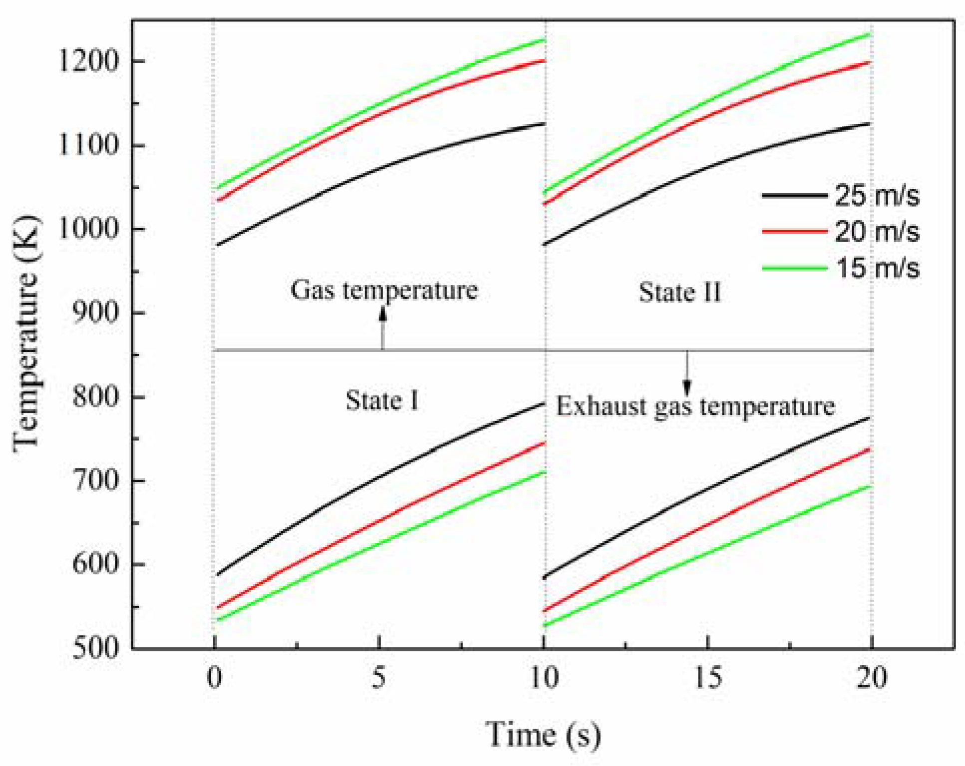
Through the operation of 11 periods, the RRCCR is in the cyclic steady state (CSS), and only the parameters in CSS are important for scientific analysis. Then, the performance and parameters of the RRCCR have periodic characteristics. Consequently, only parameters in one period during the CSS are analyzed, and the time shown in this paper is in one period, using a relative expression. In fact, the ULCVG flow is fluctuating, which directly reflects the change of the inlet velocity. In order to simplify the calculation, three cases are simulated and analyzed assuming that the inlet methane concentration is fixed at 2%, and the inlet velocity is defined as three cases, 15 m/s, 20 m/s, and 25 m/s, respectively.
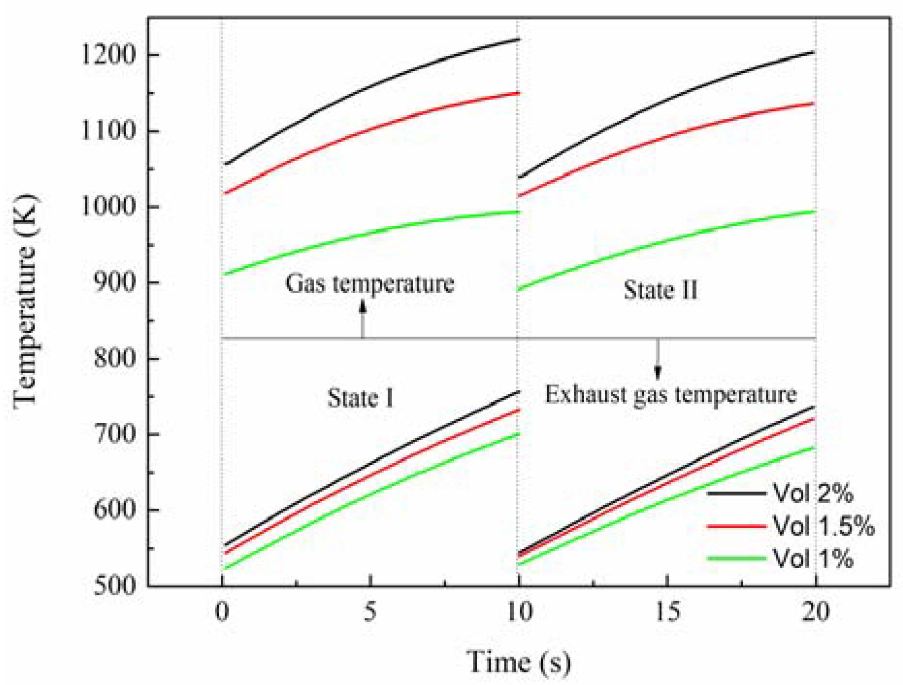
In Figure 1 state I is between two adjacent dashed lines on the left side, and state II is between two adjacent dashed lines on the right side. The gas temperature is in areas above the solid line, while the exhaust gas temperature is in areas below the solid line. When the inlet velocity is raised from 20 m/s to 25 m/s, at the initial time the outlet gas temperature decreases by around 5%, from 1035 K to 981 K, and the outlet exhaust gas temperature increases by about 9%, while at the end time the outlet gas temperature decreases by about 6%, from 1198 K to 1125 K, and the outlet exhaust gas temperature increases by about 5.7%. Therefore, it is concluded that, as the inlet velocity increases, the outlet gas temperature decreases monotonically, and the outlet exhaust gas temperature increases gradually. Consequently, increasing inlet velocity lessens the performance of the reactor. Nevertheless, when the inlet velocity is reduced from 20 m/s to 15 m/s, at the initial time the outlet gas temperature increases by around 1%, from 1035 K to 1049 K while, at the end time, the outlet gas temperature increases by about 3%, from 1198 K to 1232 K. Based on the inlet velocity of 20 m/s, there is the same increment or decrement of velocity, but the different variations of temperature reveal that the outlet gas temperature is more sensitive to the increment of the inlet velocity, which should be paid more attention in the design process. Additionally, it can be seen that the variation of the outlet exhaust gas temperature is approximately linear due to the effect of thermal inertia of the reactor wall. Further, this rule can be used to roughly evaluate the outlet exhaust gas temperature.
As implied in Figure 2, the inlet velocity exerts an important effect on the methane conversion rate. As the inlet velocity increases, the methane conversion rate decreases. When the inlet velocity increases from 20 m/s to 25 m/s, the maximum methane conversion rate is reduced by about 5%, from 95% to 90%, while the minimum value is greatly reduced by about 16%, from 90% to 75%. However, when the inlet velocity is reduced from 20 m/s to 15 m/s, the maximum methane conversion rate is only raised by about 4%, but up to 99%, while the minimum value is changed from 90% to 95%, an increment of 5%. The gas residence time in the channel becomes short due to the improving inlet velocity, resulting in the decrease of the density of the adsorption reaction. Therefore, there are less time and fewer species for reactions to take place, which can decrease the methane conversion rate. There is the same variation of the inlet velocity by 25%, but the outlet gas temperature and methane conversion rate have differences of about 2–6 times, meaning that the performance of the RRCCR is sensitive to the increase of the inlet velocity. Meanwhile, there is a critical value for the inlet velocity. If the inlet velocity is less than that value, it is difficult to improve the performance of the RRCRR. Therefore, there is a stable and narrow range for the inlet velocity to maintain the superior performance of the reactor.
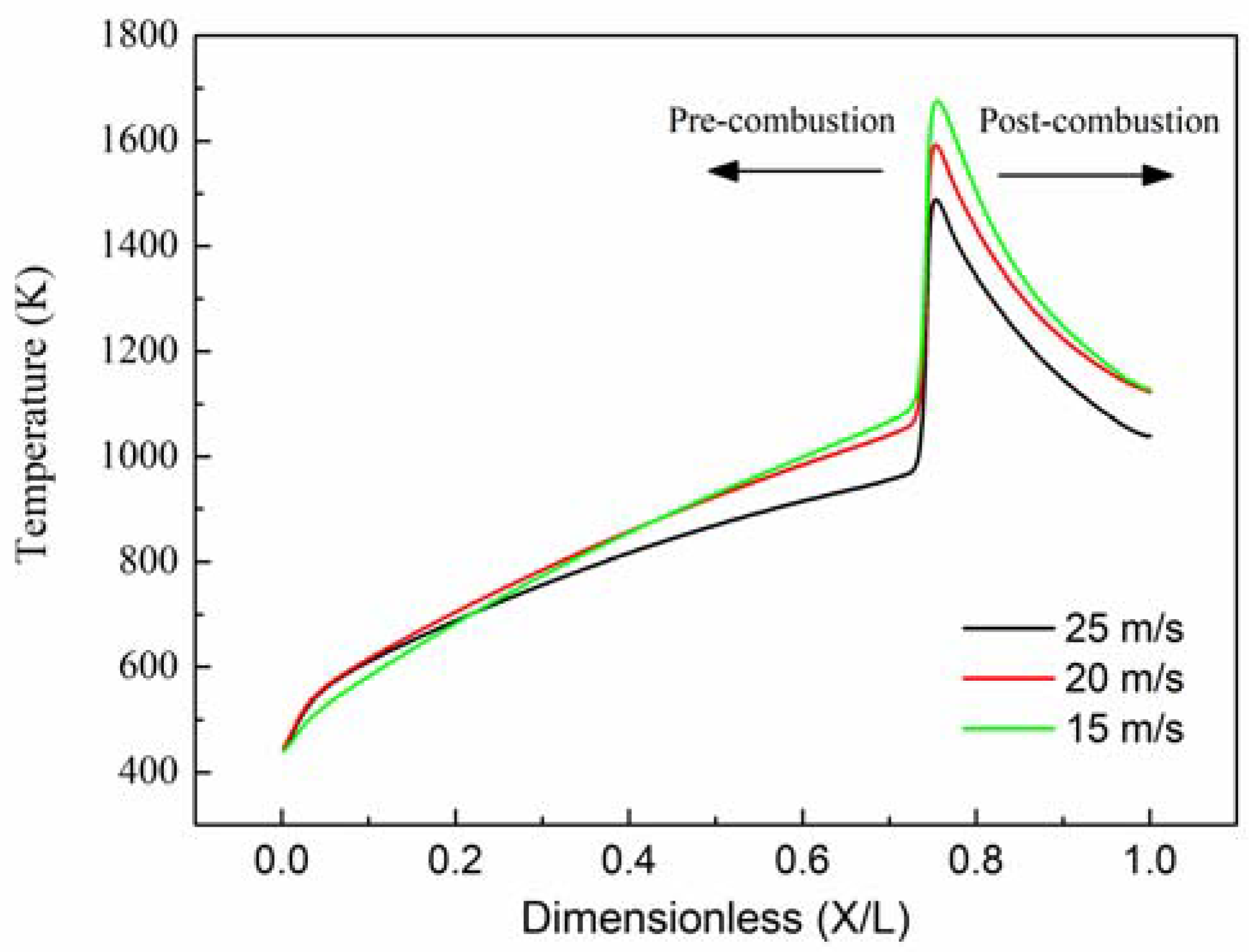
In that the temperature of hot-spots gradually increase in the same location, just the profiles of wall temperature at the end time of each state are required to be analyzed and shown in Figure 3. Clearly, the profiles of the wall temperature have a similar trend even at different inlet velocities. The wall temperature increases slightly at the pre-combustion zone, and decreases rapidly at the post-combustion zone. Due to the low thermal conductivity, the upstream heat transfer through the wall is choked. Consequently, it is easy to form hot-spots at the location of ignition zone. Additionally, the temperature of hot-spots is over 1000 K at the end time of state I/II, and it can be seen as a successive ignition source which is extremely beneficial to the catalytic ignition of methane. Nonetheless, increasing the inlet velocity can result in the decrease of the temperature of hot-spots, and rotation is favorable to avoid the further accumulation of heat in the reactor.
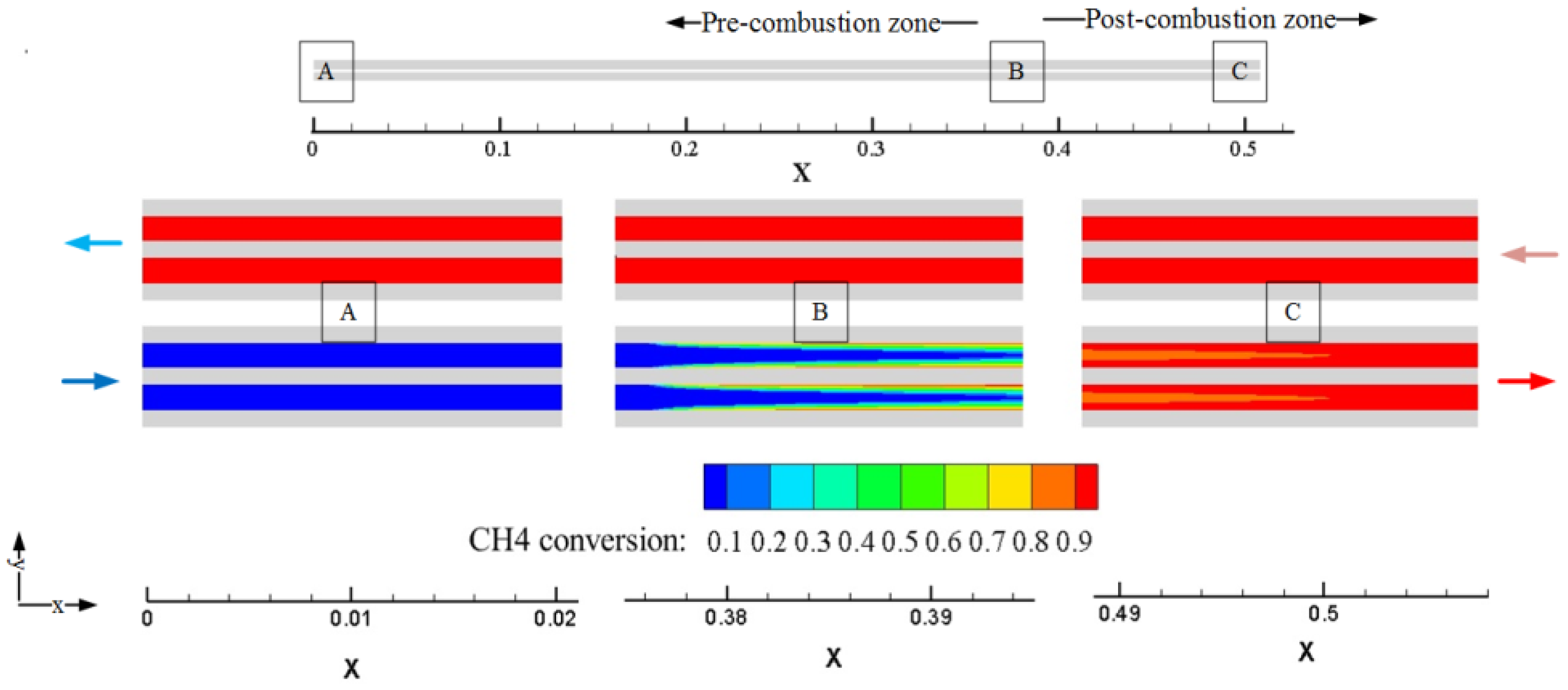
Since there is a high aspect ratio of the channel (about 423), the contour of partial amplification is used to analyze the methane conversion in the channel. Figure 4 shows the calculation model and the contour of partial amplification in zone A, B, and C. The contour at zone A demonstrates that the methane is not oxidized, as there is only heat transfer at the pre-combustion zone. It is apparent at zone B that the catalytic combustion starts from the surface of the reactor, and quickly expands to the middle area along the flow direction. Through continued combustion at the post-combustion zone, the methane conversion is over 90% at zone C, and the distribution of the outlet gas temperature is relatively uniform.
2.2. Effect of Inlet Concentration
If methane is completely converted, the estimated adiabatic flame temperature increase by 265 K per 1%vol. of methane [21], meaning that methane concentration exerts a direct impact on performance of the reactor. The investigations on the effect of inlet concentration are helpful to master the performance of the reactor, because the inlet methane concentration is fluctuating with the actual ULCVG flow. First, the inlet velocity is fixed at 20 m/s, and the effects of three different methane concentrations (1%, 1.5%, and 2%) on the performance of the reactor are, respectively, studied. Finally, the inlet velocity is also changed according to the low methane concentration to maintain a high outlet gas temperature and methane conversion rate, so that high performance can be achieved.
It can be seen in Figure 5 that, during operation, as methane concentration increases, the outlet gas temperature also increases, but the outlet exhaust gas temperature is gradually reduced. For different methane concentrations, the outlet gas temperature is very different. A typical methane concentration (1.5%) increases by approximately 33%, and the increase of the outlet gas temperature is about 6–8%. However, it should be noted that the methane concentration (1.5%) decreases by approximately 33%, and the outlet gas temperature drop is about 8–20%. Especially in the conditions of 1% vol. and 20 m/s, it is difficult to achieve the CSS, because the outlet gas temperature becomes smaller and smaller. The reduction of the methane concentration reduces the density of the adsorption reaction, which further decreases the outlet gas temperature. Eventually, it is unable to establish the self-sustaining operation of the reactor. As mentioned previously, it can be drawn that when the inlet velocity is fixed, there is a corresponding range of methane concentrations to achieve satisfactory performance of the reactor, but the actual concentration will vary depending on the system of interest.
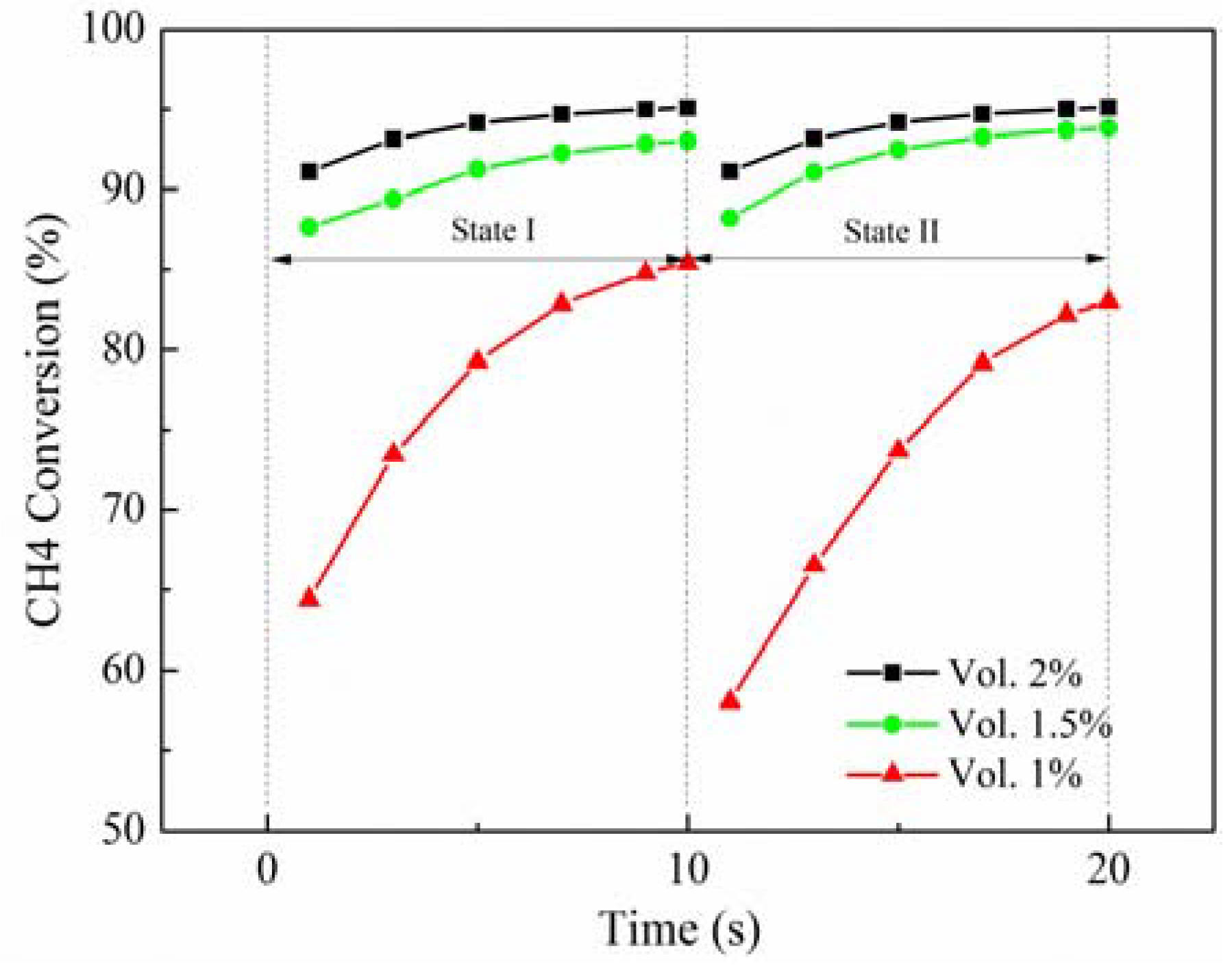
Figure 6 demonstrates that the methane conversion rate is reduced as the inlet methane concentration decreases. For example, under the condition of 2% methane, the methane conversion rate is higher than 91%. Under the condition of 1.5% methane, the methane conversion rate is approximately 86–92%. However, with 1% methane, during the operation of the reactor, eventually the self-operation cannot be achieved, since the amount of oxidized methane is getting smaller and smaller. Fortunately, due to the thermal inertia of the reactor wall, the reactor with mediocre performance can still maintain for a certain time under the condition of high inlet velocity (20 m/s). Therefore, the lower inlet methane concentration needs smaller inlet velocity so that methane has sufficient residence time to occupy the active vacancy.
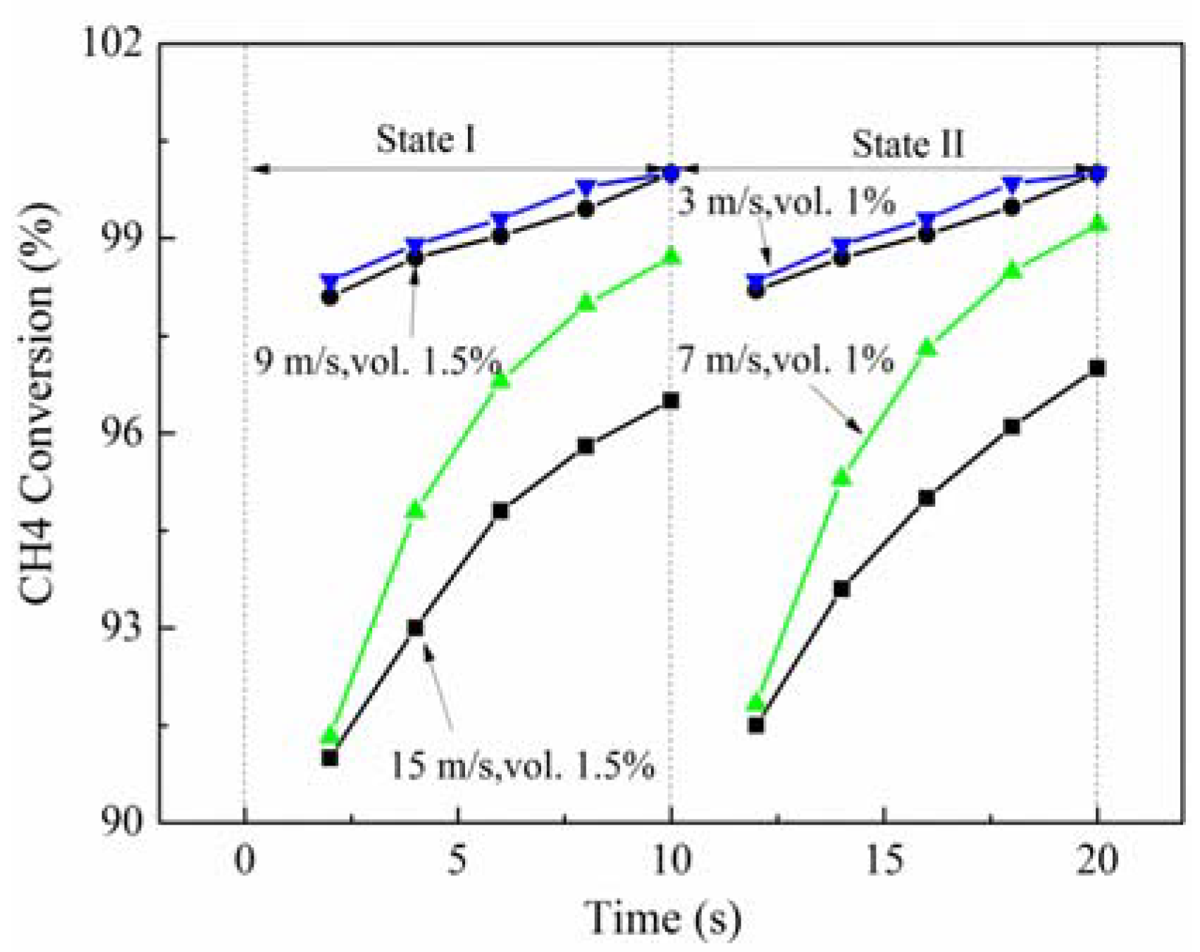
In the conditions of high inlet velocity (20 m/s) and low concentration (1%vol.), the reactor cannot be stable. Based on the previous results, the reduction of the inlet velocity is beneficial to improve the methane conversion rate. Thus, the effects of low inlet velocities on the combustion of methane are studied at low inlet concentration (1.5% and 1%vol.). The results presented in Figure 7 indicate that, at low concentration (1.5%vol.), when the inlet velocity is 15 m/s, the methane conversion rate is over 90%. When the inlet velocity is reduced to 9 m/s, the methane is almost completely oxidized. Additionally, when the inlet methane concentration is lower (1%vol.), the methane conversion is above 90% at the inlet velocity of 7 m/s, and above 97% at the inlet velocity of 3 m/s.
When the methane concentration is low, reducing the inlet velocity is the most direct method to maintain the reactor at high performance. When the methane concentration is high, a high inlet velocity will decrease the reactor performance, and a low inlet velocity will result in the wall temperature to be close to the permissible limit of most materials.
2.3. OperationalDiagram
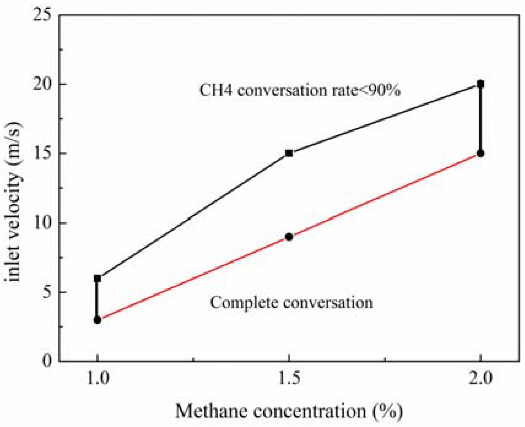
According to the previous results, the inlet velocity and concentration have a major impact on the stability and performance of the reactor. To determine the highly-stable and efficient working envelops, some restrictions are given, such as methane conversion over 90%, and an outlet exhaust gas temperature below 750 K.
The operating map of the RRCCR can be found in Figure 8. The high-velocity limit is determined by the upper curve. The velocity is above this curve, leading to a reduction of the methane conversion rate, and even combustion blowout. The low-velocity limit is determined by the lower curve, which is determined by the nearly complete methane conversion. Between the two curves, the reactor has superior performance which is desired to be maintained in actual operation. Even if the inlet concentration is variable, there is a reasonable inlet velocity to enable the reactor to achieve efficient and stable operation. Hence, this finding is very helpful for design, but actual values should vary according to the system of interest.
3. Rotary Regenerator Type Catalytic Combustion Reactor
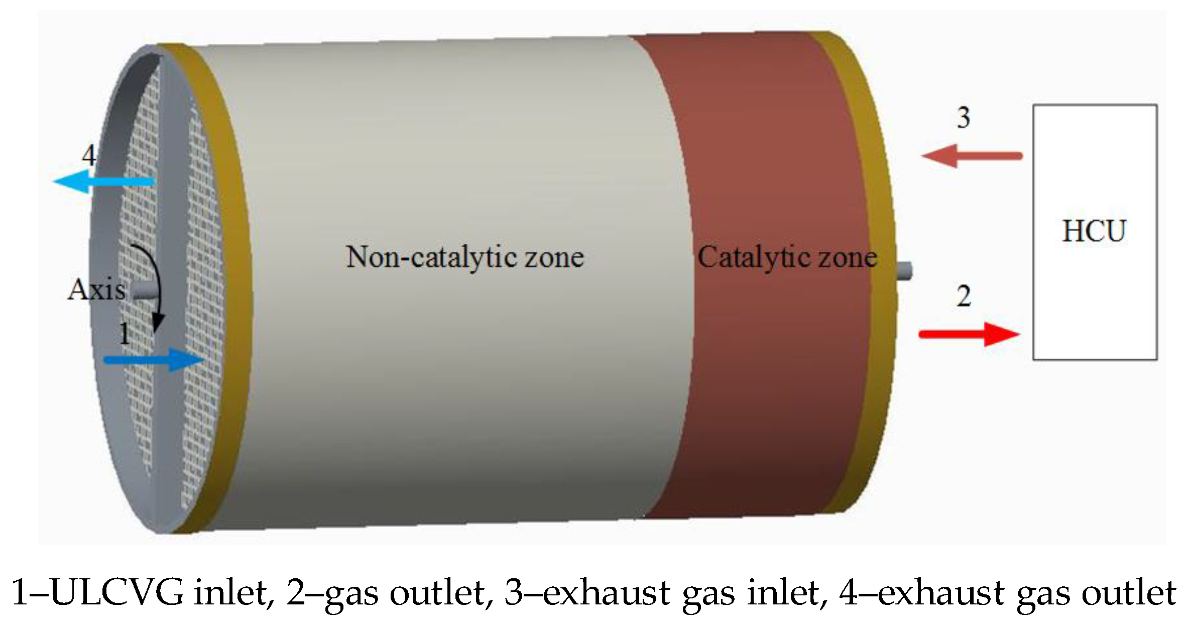
A schematic diagram of the RRCCR is shown in Figure 9, and it can be seen that the main part is a ceramic monolith reactor with walls coated by a porous material including catalytically-active particles. Monolith structures play a significant role in energy applications and environmental protection, which includes integration of various process operations, such as chemical reactions, separation, and heat exchange [22]. The concept of the RRCCR is proposed based on the principles of catalytic combustion for lean concentration and low-temperature ignition. The principle of autothermal operation is that sufficient preheating can be achieved by heat storage and be released alternately in the incremental rotary reactor. In contrast to the metal regenerator, the ceramic core can effectively allow more heat to be recovered and reused [19]. For convenience of description, the RRCCR is artificially divided into combustion and heat sides, eliminating ULCVG mainly at the combustion side and achieving exhaust gas heat recovery primarily at the heat side.
Natural gas as the primary fuel is used to launch the reactor and achieve the cyclic steady state. Then the fuel is transformed to ULCVG. Compressed ULCVG pours into the reactor from 1 and is heated to the catalytic ignition temperature of methane. Subsequently, high-temperature gas is generated due to the exothermic reaction. The high-temperature gas releases heat in the heat consumption unit (HCU) and enters the reactor in the opposite direction again. Then the exhaust gas releases heat which is trapped inside the reactor bed on the heat side. Finally, the exhaust gas is discharged into the environment from 4.
Owing to the limited heat storage and incoming cold gas flow, after a period of time the reactor wall cannot preheat the ULCVG to undergo flameless combustion. However, the incremental rotation through a certain number of degrees, such as 90 or 180 degrees, can realize the combustion again, because in the reactor a part of the heat side with sufficient heat is changed to a part of the combustion side. After the spinning motion, the reactor will be suspended for a semi-cycle, approximately from 5 to 20 s. Here the rotation plays the role of a flow reversal valve. Finally, the operational stability is realized through this circulation.
The RRCCR with ULCVG as the primary fuel can provide energy products with ultra-low pollution emission and has a compact structure and flexible operation. Additionally, all the high-temperature gas production is used directly to produce electricity or other energy, and exhaust gas is merely applied to preheat the incoming mixture airflow. Moreover, the RRCCR can be used in distributed energy generation systems. The production would be a source of heat, and can be used to drive a turbine to provide electricity, or can be used in a heat exchanger to produce hot water for local inhabitants. Furthermore, residual heat can be used by an organic Rankine cycle system to generate electricity.
4. Numerical Models and Simulation Approach
4.1. Model Geometry and Mesh
For a monolith reactor model, usually only one channel is required to be analyzed due to assuming that all channels behave essentially alike. However, during the operation of the RRCCR, the catalytic combustion and heat recovery occur on different sides, and only one channel cannot reflect the characteristic of the RRCCR. Since the reactor rotates 180 degrees each time, a reduced 2D model shown in Figure 10 with four parallel channels is presented, enabling the assessment of the effects of different velocities and concentrations on the performance of the RRCCR. The geometry model described herein is reasonably simplified in order to save simulation resources and cost, which can simulate the coupling of the fluid flow, rotation, heat transfer, and catalytic combustion. For this model, the combustion occurs in the two adjacent channels, while the heat recovery occurs in the other two adjacent channels. The related parameters can be found in Table 1.
Both solid and fluid fields are generated by a quadrilateral mesh. However, different mesh generation strategies in fluid and solid domains are adopted due to the difference between the anisotropy of the fluid near the wall and the isotropy of the solid. As the fluid field, the mesh node spacing (0.01 mm) is refined close to the wall in the radial direction. As the solid field, the grid node spacing (0.3 mm) is uniform in the radial direction. The mesh independent verification is studied by 30,000, 60,000, and 120,000 mesh cells, respectively. Finally, the 60,000 mesh cells case is adopted regarding the accuracy and calculation cost.
4.2. Reaction Mechanism and Mathematical Model
Since the gas calorific value is less than 3 MJ/Nm3 and the height size is smaller than the quenching diameter (less than 2.25 mm) of the gas phase reaction with low thermal conductivity, the gas phase reaction is ignored [23]. Additionally, as the aspect ratio of a channel is very high (about 423), the radiation transport is neglected as it has scarcely any effect on the temperature distribution within the monolith channels for the ceramic support materials [24]. Computational Fluid Dynamics (CFD) models are able to predict a very complex flow field, even combined with catalytic combustion, which is used for the management, design, and operation of catalytic reactors [25,26]. Hence Ansys Fluent 15.0 (ANSYS, Pittsburgh, PA, USA), combining multi-step methane reactions on Pt, is used to perform this simulation. This mechanism contains seven adsorption reactions, 11 surface reactions, and five desorption reactions involving 11 surface species, i.e., Pt(s), CH3(s), CH2(s), CH(s), C(s), CO2(s), CO(s), H2O(s), OH(s), H(s), and O(s) [27].
The calculated models are 2D unsteady, all the mathematical models are described as follows, and the model equations are discretized by a finite volume formulation based on quadrilateral mesh.
Continuity equation:
Momentum equation:
Energy equation:
Component equation:
Solid wall heat conduction equation:
Ideal gas equation:
4.3. Simulation Methods and Boundary Conditions
The period of the RRCCR, including state I and state II, is 20 s. The stationary time is 10 s in each state. At the end time of each state, the reactor is rotated rapidly by 180 degrees. Therefore, the rotation time is neglected. The numerical calculation is carried out by modifying the position of the inlet and outlet according to Figure 10 and Table 2. For example, in state I, the ULCVG comes into the reactor from inlet 1, and leaves the reactor from outlet 2. In state II, however, the inlet and outlet location of the ULCVG is changed: the ULCVG enters the reactor from inlet 4 and leaves the reactor from outlet 3.
In a typical 100 kW stage microturbine, the pressure ratio is about 3 and the temperature drop in the turbine is about 220 K. Through the compressor, the ULCVG with a temperature of 427 K is admitted into the reactor. Hence, the temperature drop in the HCU is assumed to be 220 K. A user-defined function (UDF) is adopted to decrease the outlet gas temperature by 220 K as the inlet condition of exhaust gas temperature after each time step. The mathematical specification of the boundary conditions is drawn up as below.
State I:
T3(t) = T2(t) − 220
State II:
T2(t) = T3(t) − 220
Coupled thermal conditions are used between the reactor wall and fluid, because both of them are in the transient case. The reaction mechanism is assigned to the interface of the fluid and reactor wall from 74.2 to 100% L. In addition, at the fluid/wall interface, no-slip and no normal species diffusive flux boundary conditions are used. The incoming flow is laminar due to the low Reynolds number, and the fluid density is assumed to be that of an ideal gas. The transport coefficients, such as viscosity and thermal conductivity, are calculated by the ideal gas mixing law, and mass diffusion coefficients are calculated by the kinetic theory. These coefficients depend on temperature and composition. The time step is set as 0.002 s, which is smaller than the residence time of gas traveling through the reactor (~0.02 s). The material of the reactor is selected by cordierite and, therefore, an-isotropic thermal conductivity is assigned to the solid field. At the entrance of the RRCCR, fixed flat profiles are assumed for velocity, species concentration, and temperature. The inlet and outlet boundary conditions are also listed in Table 2. Additionally, a linear temperature distribution from 420 K to 950 K is assigned to the initial wall by UDF. Parallel functions are used by means of the segregated solver of ANSYS Fluent 15.0 and the cyclic steady state (CSS) is obtained after 11 periods.
is the methane conversion rate, defined as:
where Cch4,in is the inlet methane concentration (by volume). Cch4,out is the outlet methane concentration (by volume).
4.4. Model Validation
According to our previous study [28], a CFD simulation is carried out based on the reaction mechanism to validate the accuracy.
In the experiment, the premixed fuel is adjusted to the desired pressure by a pressure reducer then passes through a 15 kW electric heater, and finally enters the catalytic combustion chamber for the catalytic reaction. There are two water-cooled probes before and after the catalytic combustion chamber to collect the sample. Finally the content of each component in the sample gas is measured by a gas chromatograph. The length of the ceramic monolith reactor is 127 mm. The diameter is 90 mm. The wall thickness is 0.18 mm, and the diameter of each channel is 1.27 mm.
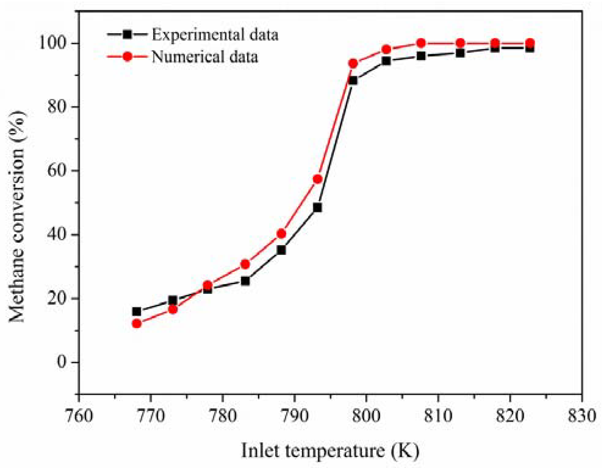
The experimental and numerical data are given in the Figure 11 under the boundary conditions of an inlet concentration of 1.96%, an inlet velocity of 6 m/s, and an inlet pressure of 2.04 kPa. The relative error between computations and experimental data is less than 7%, the main reason is that it is difficult to guarantee the operation of the experiment at the adiabatic condition. Figure 11 illustrates that the methane conversion has a satisfactory agreement between them. The methane conversion increases with the temperature increase of the incoming premixed fuel. Therefore, it is believed that the numerical models adopted in this study are reasonably accurate.
5. Conclusions
RRCCR is a promising and feasible technology, which is worthy to be popularized for the utilization of ULCVG. It not only diminishes the effect of methane on the greenhouse effect, but also expands the supplement of energy. The influences of inlet velocity and concentration on the reactor are analyzed by CFD technology. In general, inlet velocity and methane concentration affect not only the gas temperature, exhaust gas outlet temperature, and methane conversion rate, but also the temperature of hot-spots in the reactor wall, which can be seen as a continuous ignition source. Thus the occurrence of catalytic combustion is not only due to sufficient preheating, but also the presence of hot spots.
First, as the inlet velocity increases, the outlet gas temperature and methane conversion rate decrease. However, the performance of RRCCR is more sensitive to the increase of velocity, which needs more attention in the design process. For example, when the inlet velocity (20 m/s) increases by 25%, the outlet gas temperature decreases by 5~6%, and the methane conversion decreases by 6–17%. On the contrary, when the inlet velocity (20 m/s) is reduced by 25%, the outlet gas temperature increases by 1–3%, and the methane conversion increases by less than 3%. As a result, in order to improve the performance of the reactor, there is only a narrow range of inlet velocities to be used.
Finally, with the increase of methane concentration, the outlet gas temperature, methane conversion rate, and peak temperature of the reactor wall have a similar trend. Relatively speaking, the performance of the RRCCR is more sensitive to the decrease of methane concentration, which should be paid more attention in the design process. When the inlet concentration is low, reducing the inlet velocity is an effective method to increase the methane conversion rate and achieve the self-sustained operation of the reactor. Moreover, when the inlet concentration (2%vol.) is reduced by 50%, the inlet velocity should be reduced by about three times to maintain methane conversion rate above 90%.
Author Contributions
Y.W. and Z.S. conceived and designed the numerical experiments; Z.S. and Z.B. performed the numerical experiments; Z.S. and X.L. analyzed the data; Z.S. and Y.W. wrote the paper.
Acknowledgments
This work was supported by the National Technology Research and Development Program of China (2014AA052803) and the National Natural Science Fund (51376123).
Conflicts of Interest
The authors declare no conflict of interest.
Nomenclature
| CMR | Catalytic monolith combustor |
| CSS | Cyclic steady state |
| HCU | Heat consumption unit |
| ULCVG | Ultra low calorific value gas |
| VAM | Ventilation air methane |
| Ds | Diffusioncoefficient (m2 s−1) |
| Wt | Reactor wall thickness (m) |
| Hd | Hydraulic diameter (m) |
| h | Mixture or solid enthalpy (J kg−1) |
| hs | Enthalpy of specie s (J kg−1) |
| L | Reactor length (m) |
| Ms | Molar mass of specie s (kg mol−1) |
| p | Pressure (Pa) |
| Rcs | Generation or consumption rate (kg m−3 s−1) |
| R | The universal gas constant, R = 8.314 (J mol−1 K−1) |
| Sh | Heat sources due to chemical reactions (J m−3 s−1) |
| t | Time (s) |
| T | Solid or gas temperature (K) |
| ui | Velocity components (m s−1) |
| xi | x or y direction in Cartesian coordinates |
| y | Vertical coordinates |
| Ys | Mass fraction of species s |
| Greek letters | |
| ρ | Gas or solid density (kg m−3) |
| μ | Mixture viscosity coefficient (N s−1 m−2) |
| λs | Thermal conductivity of specie s (W m−1 K−1) |
| λw | Solid thermal conductivity (W m−1 K−1) |
| Subscripts | |
| s | s-th species |
| i, j | x or ydirection |
References
- Warmuzinski, K. Harnessing methane emissions from coal mining. Process Saf. Environ. Prot. 2008, 86, 315–320. [Google Scholar] [CrossRef]
- Karakurt, I.; Aydin, G.; Aydiner, K. Mine ventilation air methane as a sustainable energy source. Renew. Sustain. Energy Rev. 2011, 15, 1042–1049. [Google Scholar] [CrossRef]
- Betta, R.A.D.; Schlatter, J.C.; Yee, D.K.; Loffler, D.G.; Shoji, T. Catalytic combustion technology to achieve ultra low NOx emissions: Catalyst design and performance characteristics. Catal. Today 1995, 26, 329–335. [Google Scholar] [CrossRef]
- Carroni, R.; Griffin, T. Catalytic, hybrid lean combustion for gas turbines. Catal. Today 2010, 155, 2–12. [Google Scholar] [CrossRef]
- Zaza, F.; Luisetto, I.; Serra, E.; Tuti, S.; Pasquali, M. Catalytic Combustion of Methane by Perovskite-Type Oxide Nanoparticles as Pollution Prevention Strategy. J. Renew. Sustain. Energy 2016, 1749, 020003. [Google Scholar]
- Setiawan, A.; Kennedy, E.M.; Stockenhuber, M. A review on the development of combustion technology for methane emitted from coal mine ventilation air systems (VAM). Energy Technol. 2017, 5, 521–538. [Google Scholar] [CrossRef]
- Su, S.; Beath, A.; Guo, H.; Mallett, C. An assessment of mine methane mitigation and utilisation technologies. Prog. Energy Combust. Sci. 2005, 31, 123–170. [Google Scholar] [CrossRef]
- Karakurt, I.; Aydin, G.; Aydiner, K. Sources and mitigation of methane emissions by sectors: A critical review. Renew. Energy 2012, 39, 40–48. [Google Scholar] [CrossRef]
- Gosiewski, K.; Matros, Y.S.; Warmuzinski, K.; Jaschik, M.; Tanczyk, M. Homogeneous vs. catalytic combustion of lean methane—Air mixtures in reverse-flow reactors. Chem. Eng. Sci. 2008, 63, 5010–5019. [Google Scholar] [CrossRef]
- Cluff, D.L.; Kennedy, C.A.; Bennett, J.G.; Foster, P.J. Capturing energy from ventilation air methane a preliminary design for a new approach. Appl. Therm. Eng. 2015, 90, 1–13. [Google Scholar] [CrossRef]
- Su, S.; Agnew, J. Catalytic combustion of coal mine ventilation air methane. Fuel 2006, 85, 1201–1210. [Google Scholar] [CrossRef]
- Everaert, K.; Baeyens, J. Catalytic combustion of volatile organic compounds. J. Hazard. Mater. 2004, 109, 113–139. [Google Scholar] [CrossRef] [PubMed]
- Su, S.; Yu, X. A 25 kWe low concentration methane catalytic combustion gas turbine prototype unit. Energy 2015, 79, 428–438. [Google Scholar] [CrossRef]
- Martinez, D.M.; Cluff, D.L.; Jiang, X. Numerical investigation of the burning characteristics of ventilation air methane in a combustion based mitigation system. Fuel 2014, 133, 182–193. [Google Scholar] [CrossRef] [Green Version]
- Iloeje, C.O.; Zhao, Z.; Ghoniem, A.F. A reduced fidelity model for the rotary chemical looping combustion reactor. Appl. Energy 2017, 190, 725–739. [Google Scholar] [CrossRef]
- Skiepko, T.; Shah, R.K. A comparison of rotary regenerator theory and experimental results for an air preheater for a thermal power plant. Exp. Therm. Fluid Sci. 2004, 28, 257–264. [Google Scholar] [CrossRef]
- Luzi, C.D.; Martínez, O.M.; Barreto, G.F. Autothermal reverse-flow reactors: Design and comparison of valve-operated and rotary systems. Chem. Eng. Sci. 2016, 148, 170–181. [Google Scholar] [CrossRef]
- Luzi, C.D.; Martínez, O.M.; Barreto, G.F. Rotary reverse flow reactor vs. adiabatic reactor with regenerative preheating-Design and comparison. Chem. Eng. Sci. 2017, 166, 246–261. [Google Scholar] [CrossRef]
- Wilson, D.G.; Ballou, J.M. Design and Performance of a High-Temperature Regenerator having very High Effectiveness, Low Leakage and Negligible Seal Wear. In Proceedings of the ASME Turbo Expo 2006: Power for Land, Sea, Air, Barcelona, Spain, 8–11 May 2006. [Google Scholar]
- Sang, Z.K.; Bo, Z.M.; Liu, X.; Weng, Y.W. Characteristic Analysis of a Rotary Regenerative type Catalytic Combustion Reactor for Ultralow Calorific Value Gas. ASME J. Energy Resour. Technol. 2017, 139, 062208. [Google Scholar] [CrossRef]
- Gosiewski, K.; Pawlaczyk, A.; Jaschik, M. Energy recovery from ventilation air methane via reverse-flow reactors. Energy 2015, 92, 13–23. [Google Scholar] [CrossRef]
- Gokalp, B. Using the three-way catalyst monolith reactor for reducing exhaust emissions. J. Renew. Sustain. Energy 2012, 4, 043114. [Google Scholar] [CrossRef]
- Ohadi, M.M.; Buckley, S.G. High temperature heat exchangers and microscale combustion systems: Applications to thermal system miniaturization. Exp. Therm. Fluid Sci. 2001, 25, 207–217. [Google Scholar] [CrossRef]
- Mazumder, S.; Grimm, M. Numerical Investigation of Radiation Effects in Catalytic Combustion. In Proceedings of the ASME-JSME Thermal Engineering Summer Heat Transfer Conference, Vancouver, BC, Canada, 8–12 July 2007. [Google Scholar]
- Benedetto, A.D.; Sarli, V.D.; Russo, G. Effect of geometry on the thermal behavior of catalytic micro-combustors. Catal. Today 2010, 155, 116–122. [Google Scholar] [CrossRef]
- Benedetto, A.D.; Landi, G.; Sarli, V.D.; Barbato, P.S.; Pirone, R.; Russo, G. Methane catalytic combustion under pressure. Catal. Today 2012, 197, 206–213. [Google Scholar] [CrossRef]
- Deutschmann, O.; Schmidt, R. Numerical Modeling of Catalytic Ignition. Symp. Int. Combust. 1996, 26, 1747–1754. [Google Scholar] [CrossRef]
- Yin, J.; Weng, Y. Investigation of combustion and thermodynamic performance of a lean burn catalytic combustion gas turbine system. Energy Convers. Manag. 2011, 52, 1711–1720. [Google Scholar] [CrossRef]
Figure 1.
The gas temperature at different inlet velocities; Cin,ch4 = 2%.

Figure 2.
The effect of inlet velocities on the methane conversion rate; Cin,ch4 = 2%.

Figure 3.
Profiles of wall temperature along the axis on combustion side. t = 10 s, Cch4,in = 2%.

Figure 4.
Contour of methane conversion. v = 20 m/s, t = 10 s, Cch4,in = 2%.

Figure 5.
The effect of methane concentrations on the gas temperature; v = 20 m/s.

Figure 6.
The effect of concentrations on the methane conversion rate. v = 20 m/s.

Figure 7.
Effect of inlet velocities and concentrations on the methane conversion rate.

Figure 8.
Operational map for methane catalytic combustion on Pt. λw = 5 W/m/K.

Figure 9.
Schematic illustration of a rotary regenerator-type catalytic combustion reactor.

Figure 10.
Schematic of the computational model.
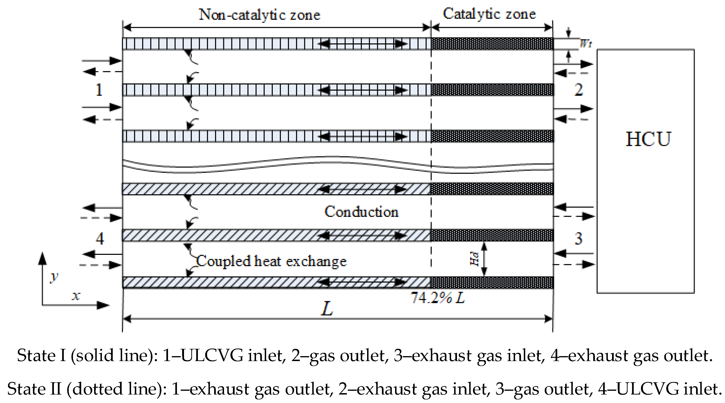
Figure 11.
Verification of the model: methane conversion.


Table 1.
Parameters of a reactor channel.
| Single Channel | Catalyst | The Properties of Cordierite | ||||
|---|---|---|---|---|---|---|
| Hd mm | Wt mm | L mm | Catalyst | Load Density kg mol m−2 | Specific Heat J kg−1 K−1 | Thermal Conductivity Wm−1 K−1 |
| 1.2 | 0.4 | 508 | Pt | 2.7063 × 10⁻⁹ | 970 | 5 |
Table 2.
Switch order and boundary conditions.
| State | Gas Name | No. Inlet | Boundary Condition | Value/m/s, K | Gas Name | No. Outlet | Boundary Condition | Values/bar |
|---|---|---|---|---|---|---|---|---|
| State I | ULCVG | 1 | Velocity inlet | u, 427 | Gas | 2 | Pressure outlet | 3 |
| Exhaust gas | 3 | Mass flow inlet | UDF | Exhaust gas | 4 | Pressure outlet | 1.15 | |
| State II | ULCVG | 4 | Velocity inlet | u, 427 | Gas | 3 | Pressure outlet | 3 |
| Exhaust gas | 2 | Mass flow inlet | UDF | Exhaust gas | 1 | Pressure outlet | 1.15 |
© 2018 by the authors. Licensee MDPI, Basel, Switzerland. This article is an open access article distributed under the terms and conditions of the Creative Commons Attribution (CC BY) license (http://creativecommons.org/licenses/by/4.0/).
Share and Cite
MDPI and ACS Style
Sang, Z.; Bo, Z.; Lv, X.; Weng, Y. Numerical Investigations of the Influencing Factors on a Rotary Regenerator-Type Catalytic Combustion Reactor. Catalysts 2018, 8, 173. https://doi.org/10.3390/catal8050173
AMA Style
Sang Z, Bo Z, Lv X, Weng Y. Numerical Investigations of the Influencing Factors on a Rotary Regenerator-Type Catalytic Combustion Reactor. Catalysts. 2018; 8(5):173. https://doi.org/10.3390/catal8050173
Chicago/Turabian StyleSang, Zhenkun, Zemin Bo, Xiaojing Lv, and Yiwu Weng. 2018. "Numerical Investigations of the Influencing Factors on a Rotary Regenerator-Type Catalytic Combustion Reactor" Catalysts 8, no. 5: 173. https://doi.org/10.3390/catal8050173
Note that from the first issue of 2016, this journal uses article numbers instead of page numbers. See further details here.