Combining Carbon Fibers with Ni/γ–Al2O3 Used for Syngas Production: Part A: Preparation and Evaluation of Complex Carrier Catalysts

Ministry of Education of Key Laboratory of Energy Thermal Conversion and Control, School of Energy and Environment, Southeast University, Nanjing 210096, China
*
Author to whom correspondence should be addressed.
Catalysts 2018, 8(12), 658; https://doi.org/10.3390/catal8120658
Submission received: 1 November 2018
/
Revised: 20 November 2018
/
Accepted: 27 November 2018
/
Published: 13 December 2018
Abstract
:To promote the adsorption and activation of carbon dioxide in the dry reforming of methane (DRM), Ni and Al2O3 were coprecipitated on activated carbon fibers (ACF). Various characterization methods were adopted in order to investigate the surface characteristics of different catalysts. Chemisorption characterization results, such as H2-temperature programmed reduction (H2-TPR), H2-temperature programmed desorption (H2-TPD), and CO2-temperature programmed desorption (CO2-TPD) illustrated that ACF in a nickel-based catalyst could enhance the basic sites and improve the metal dispersion on a catalyst surface, which is beneficial for the adsorption and activation of feed gas. The coprecipitated coating on ACF proved by scanning electron microscope (SEM) can prevent the carbon of ACF from participating in the reaction, while retain good surface properties of carbon fibers. X-ray diffraction (XRD) patterns illustrated that the ACF in a nickel-based catalyst could decrease the crystallite size of the spinel NiAl2O4, which is beneficial for methane reforming. In addition, the Fourier transform infrared spectroscopy (FTIR) of different catalysts revealed that the added ACF could provide abundant functional groups on the surface, which could be the intermediate product of DRM, and effectively promote the reaction. Different to the catalyst supported on single alumina, the performance evaluation and stability test proved that the catalyst added with ACF exhibited a better catalytic performance especially for CO2 conversion. Moreover, based on the characterization results as well as some related literature, the dry reforming mechanism over optimum catalyst was derived.

1. Introduction
The syngas (H2 and CO) commonly used for organic synthesis is mainly obtained by coal gasification and the steam reforming of methane (SRM) [1]. In recent years, the carbon dioxide reforming of methane (DRM) has attracted considerable attention [2,3] for its comprehensive utilization of two main greenhouse gases [4,5].
For the moment, the catalyst used for SRM is a nickel-based catalyst supported on alumina, because of its low cost and relatively high activity [6,7,8]. However, it is not recommendable to apply into DRM directly, for the easy carbon deposition and sintering [9]. To modify the catalyst with a great anti-coking performance is a prerequisite for DRM industrialization. It is known that carbon deposition is due to the active carbon from methane cracking, which cannot promptly react with CO2, thus becoming inactive carbon. Compared with steam, carbon dioxide with less carbon removal capacity cannot remove the intermediate carbon in a timely manner. So, the key to eliminating carbon deposition is to promote the activation of CO2. It has been proven that the support greatly affects the activation of CO2 during DRM, due to the varying active surface area and acid base property [10]. Related literature indicates that Lewis basic sites on support could promote the chemisorption of CO2 and accelerate eliminating coke by the reaction of CO2 with deposited coke to form CO during the DRM reaction [11,12]. So, various metal oxides [13,14,15,16,17,18,19] (La2O3, SiO2, MgO, CaO, ZnO, CeO2, TiO2, ZrO2, and so on) are applied for the modification of supports.
Carbon material, as a unique catalyst carrier, has attracted much attention for its great surface characteristics [20,21,22]. Much research about nickel-based catalysts supported on carbon materials [23,24] has been reported. For example, Bradford [25] and Ferreira-Aparicio [26] prepared the Ru-based catalyst, supported on carbon black and graphite, respectively, used for DRM, and illustrated that the support serves as a collector of CHX species, which reduces the residence time of carbon species on Ru phase, and therefore leads to a very stable catalyst. Among the numerous carbon materials, the alkaline activated carbon fibers (ACF) draw our attention, for their high specific surface area, rich functional groups, and abundant basic sites on surface [27]. However, based on our former research [28], the pure carbon fibers that served as support could easily react with CO2 and lead to the deactivation of the catalyst, because of the pore structure collapse; although they could restrain carbon deposition.
Herein, we consider the combination of carbon fibers and nickel-based alumina catalyst systems. The great surface characteristics of carbon fibers will contribute to the adsorption and activation of CO2. In this work, nickel and alumina would be coprecipitated on the surface of ACF. A series of nickel-based catalysts were configured by combining γ–Al2O3 with ACF powder by coprecipitation. The obtained catalysts would be applied in DRM to illustrate the catalytic performance. Then, the mechanism of reforming would be investigated based on the related characterization results.
2. Results and Discussion
In this work, to obtain the optimum proportion of ACF to γ–Al2O3, various catalysts with different mass ratios of ACF/γ–Al2O3 (from 0:10 to 10:0) were prepared by coprecipitation. The catalytic performance of the different prepared catalysts at 650 °C and 750 °C are shown in Figure S1. It is found that the optimum ratio of ACF/γ–Al2O3 is 5:5. So, in the following research, the mass ratio of ACF/γ–Al2O3 for complex carrier catalysts would be 5:5. This kind of catalyst will be named as Ni–γ–Al2O3/ACF, and the catalysts supported on single γ–Al2O3 and ACF will be named Ni–γ–Al2O3 and Ni/ACF, respectively.
2.1. Characteristic of Catalysts
2.1.1. Surface Characterization
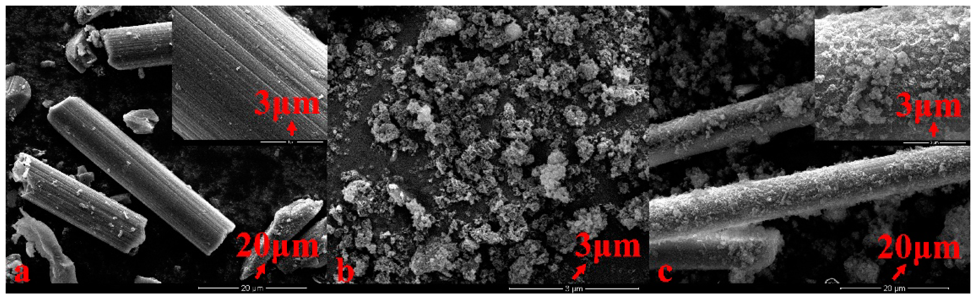
To illustrate the surface morphology of the prepared catalysts, SEM was conducted as shown in Figure 1. It can be found that the solid solution of the nickel and alumina uniformly covers the surface of the carbon fibers. The coprecipitated coating can effectively inhibit the carbon of ACF from participating into the reaction, while retaining the good surface properties of the fibers. Meanwhile, the added ACF could also remarkably improve the surface structure of the nickel-based catalyst, especially for the specific surface area, as shown in Table S1, which is favorable for the adsorption of raw gas. In addition, we conducted an energy dispersive spectroscopy (EDS) of the catalysts Ni–γ–Al2O3/ACF, as shown in Figure S2. Based on the EDX result, the mass content of Ni on the surface of the catalyst is 1.43%. Because of the co-precipitation method, some of the nickel is covered by alumina, which results in the smaller mass content of Ni on the surface of the catalyst than the total Ni loading in the catalyst.
2.1.2. Chemisorption Characterization
To better explain the influence of ACF on the catalyst system, the chemisorption characterizations (H2-temperature programmed reduction (H2-TPR), H2-temperature programmed desorption (H2-TPD), and CO2-temperature programmed desorption (CO2-TPD)) were conducted, as shown in Figure 2.
The interaction between the active metal and support was revealed by H2-TPR, as shown in Figure 2a. When the nickel and alumina coprecipitated on the surface of ACF, the reduction peak appears at a higher temperature compared with the nickel-based catalyst coprecipitated with single alumina or ACF. It can be considered that the addition of ACF leads to the stronger metal–support interaction, which is beneficial to anti sintering. This could be attributed to the formation of the spinel of NiAl2O4, which would be proven by the subsequent XRD. To obtain the proportion of Ni in direct contact with alumina (and that is able to produce NiAl2O4 spinel) and the proportion of Ni in direct contact with ACF, we conducted the peak fitting of the H2-TPR curve of the catalyst Ni–Al2O3/ACF, as shown in in Figure S3 and Table S2. With the combined proportion of the peak area with the result of EDS, the proportion of the different nickel on the catalyst surface could be calculated. The proportion of the free nickel, the nickel in direct contact with ACF, and the nickel in direct contact with the alumina is 0.174%, 0.094%, and 1.623%, respectively.
As is known to all, the role of support is to provide a high specific surface area so that the active metal can be maximally dispersed [29]. The H2-TPD could illustrate the metal dispersion and active sites. As presented in Figure 2b, the H2 desorption temperature for the catalyst supported on alumina is about 460 °C. The minimum peak area and lower desorption temperature proves the poor metal dispersion of the catalyst supported on the alumina. While for the catalyst supported on ACF, the higher specific surface area results in a much better metal dispersion, which leads to the larger desorption peak area and higher desorption temperature existing at 660 °C. When the nickel and alumina coprecipitated on the surface of ACF, the H2-TPD of the catalyst supported on double supports exhibits two desorption peaks at 580 °C and 890 °C, respectively. It has been proven that there are two kinds of active sites for the catalyst supported on complex supports. The first desorption peak existing at 580 °C is the active site resulting from the combination of nickel and alumina. The second desorption peak existing at 890 °C is the active site resulting from the combination of nickel and carbon fibers. Compared to the catalysts supported on a single support, the desorption peak of the active site from the combination of the nickel and alumina is enhanced, while the desorption peak of the active site from the combination of nickel and carbon fibers is decreased. This is consistent with the two reduction peaks of the catalysts shown by H2-TPR.
Another function of support is to provide the acid or basic sites [29] on the catalyst surface, which is beneficial for the adsorption and activation of feed gas. The CO2-TPD of three catalysts was conducted in order to investigate the basic sites on the surface, as presented in Figure 2c. Each catalyst presents three desorption peaks, which correspond with weak, intermediate strength, and strong basic sites, respectively. It is mainly the intermediate strength and strong basic sites on the surface of the catalyst Ni/ACF. While for the catalyst supported on alumina, it is mainly the weak basic site on the surface. As we know, the basic site is favored for the adsorption and activation of carbon dioxide [10,11,12]. When adding the ACF into the nickel-based catalyst supported on alumina, the basic sites on the catalyst surface are strengthened. The strengthened intermediate strength and strong basic sites are helpful for the adsorption of acid carbon dioxide, because of the abundance of the OH group. So, in consideration of the results of the specific surface area and pore structure parameters, it is concluded that the ACF could promote the chemisorption and activation of CO2.
2.1.3. X-Ray Diffraction
To explain the chemisorption characterization results and illustrate the crystal structure of the prepared catalysts, the XRD for ACF, Ni-Al2O3, and Ni-Al2O3/ACF was conducted as shown in Figure 3. The two catalysts were not reduced before XRD. As can be seen in Figure 3, both of the catalysts exhibit three diffraction peaks of spinel NiAl2O4 around 37°, 45°, and 66°. However, because of the addition of ACF, the crystallite size of the spinel in the different catalysts in different. Table 1 shows the crystallite sizes of the spinel at different two-Theta in two catalysts, calculated by the Scherrer equation [30]. After adding ACF into the catalyst Ni–Al2O3/ACF, the crystallite size of the spinel is obviously smaller than that in Ni–Al2O3. The smaller structure of the spinel NiAl2O4 is beneficial to anti sintering.
2.1.4. Fourier Transform Infrared
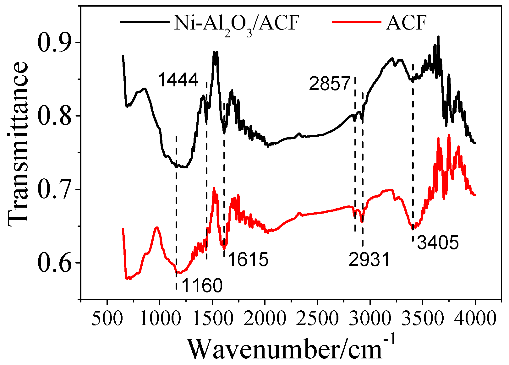
To reveal the different functional groups on the catalyst surface, the FTIR spectra of ACF and catalyst Ni–Al2O3/ACF was conducted, as shown in Figure 4. The broad adsorption peak at 3405 cm−1 could be attributed to the –OH stretching vibration [31], and the weak adsorption peaks at 2931 cm−1, 2857 cm−1, and 1160 cm−1 could be ascribed to the stretching vibration of –CH3, –CH2–, and –CH–, respectively [32]. The characteristic adsorption peak at 1615 cm−1 is generated by the C=C or C–O stretching vibration [33]. The weak adsorption peak at 1444 cm−1 is due to the stretching vibration of CH3O– [34]. The FTIR spectra reveals that the added ACF in the catalyst Ni–Al2O3/ACF provides abundant oxygen functional groups and methyl groups on the surface, which could be the intermediate product of dry reforming methane, and effectively promote the reaction. The abundant functional groups from ACF could provide the basic sites on the catalyst surface, which is favored for the adsorption and activation of CO2.
2.2. Evaluation of Catalytic Performance
2.2.1. Catalyst Stability Test
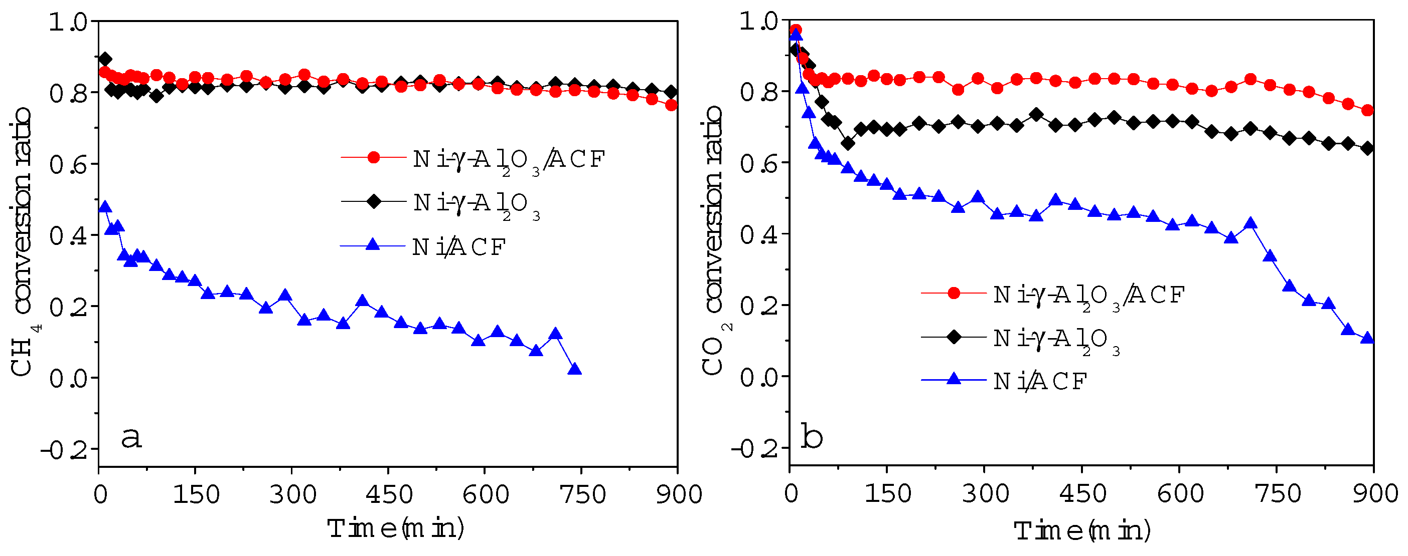
To illustrate the influence of the added ACF on the catalytic performance, the stability test of three catalysts (the ratios of ACF/γ–Al2O3 are 5:5, 0:10, and 10:0, respectively) at 750 °C were conducted, as presented in Figure 5. Apparently, combining ACF with γ–Al2O3 is beneficial for the catalytic performance. Compared with the other two catalysts, the catalyst supported on single ACF is easy to inactivate in 900 min. However, when adding ACF into the nickel-based alumina system, the catalytic performance was different. It can be found that the added ACF leads to the remarkable increase in the CO2 conversion ratio at 750 °C for catalyst Ni–γ–Al2O3/ACF. The catalyst supported on the composite supports shows no obvious deactivation in 900 min. This could be ascribed to three reasons. The first is that the coprecipitated coating of Ni and Al2O3 on the ACF surface, proven by the SEM result, could restrain the carbon of the ACF from participating in reforming, while retaining the good surface properties of the fibers. Then, the ACF with abundant basic sites, proven by CO2-TPD, is helpful for the chemisorption and activation of CO2 [10,11,12], and could accelerate the removal of deposited coke to form CO during reforming. Furthermore, the theoretically ideal solid solution [35] of Ni and Al2O3 formed by the coprecipitation method is beneficial to control the particle size of metallic nickel, and could improve the catalytic performance.
2.2.2. Carbon Equilibrium in Gas Phase
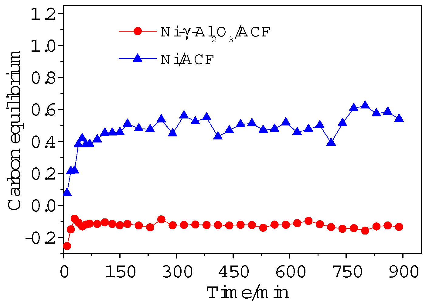
Our former research proved that the carbon from the support could be involved in reforming for the catalyst supported on the single ACF, which leads to the rapid deactivation [28]. The combination of ACF and alumina by coprecipitation could solve the problem effectively. The carbon equilibrium of dry reforming in the gas phase with two catalysts (Ni–γ–Al2O3/ACF and Ni/ACF) is calculated, as presented in Figure 6. For the catalyst supported on a single ACF, the carbon content in the produced gas is nearly 50% higher than that in the feed gas, which could illustrate that the carbon of the ACF is remarkably involved in reforming. While the combined ACF with alumina acts as composite supports, the extra carbon content for the catalyst is decreased remarkably. The covered solid solution of nickel and alumina on the surface, proven by SEM, could effectively prevent the carbon of ACF from participating in the reaction.
2.2.3. Catalytic Performance at Different Temperatures
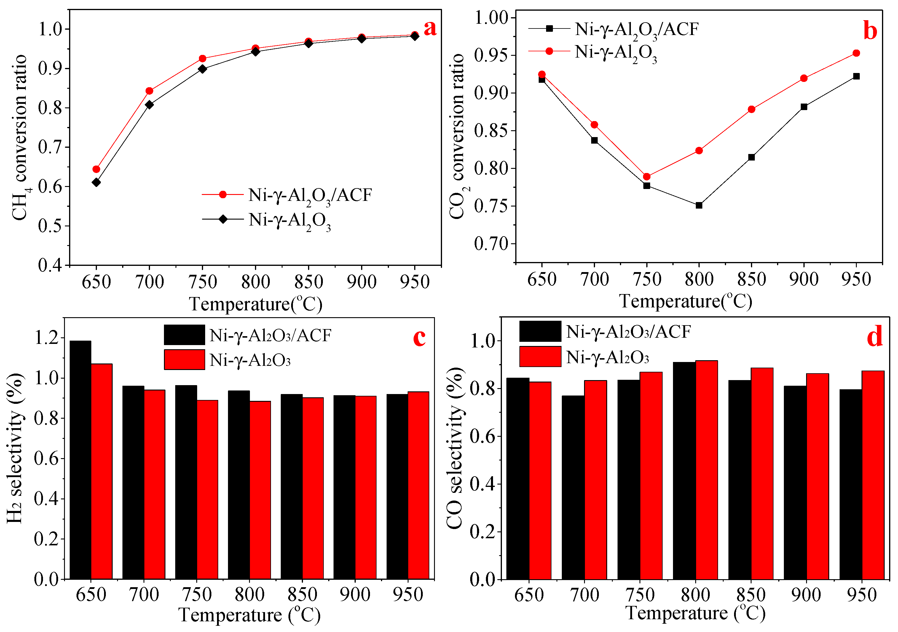
To further illustrate the unique advantages of ACF, the catalytic performance of two catalysts (Ni–γ–Al2O3/ACF and Ni/ACF) at different temperatures was conducted, as shown in Figure 7. Apparently, adding ACF into the nickel-based catalyst supported on the alumina is beneficial for the catalytic performance at different temperatures, especially for the conversion ratio of CO2. At a higher temperature, the conversion ratio of CO2 for catalyst Ni–γ–Al2O3/ACF is much higher than that without ACF. The added ACF for the catalyst Ni–γ–Al2O3/ACF promotes the chemisorption and activation of CO2, which could accelerate the reaction between the adsorbed CO2 and the intermediate active carbon from methane dissociation [11], which then leads to the higher conversion ratio of CH4 and CO2. Furthermore, with the increase of temperature, the conversion ratio of CO2 decreases first and then increases. For the methane reforming system, the increased temperature is beneficial for the endothermic reactions, including the dry reforming of methane and methane cracking, while it inhibits the exothermic reaction, including the reaction between ACF and CO2. The combined effects of these reactions lead to this phenomenon. In addition, it can be seen that the selectivity of both H2 and CO is near 1, which indicates that the main reaction in the feed gas was a dry gas reforming reaction with only a few side reactions.
2.3. Mechanism Analysis for Reforming
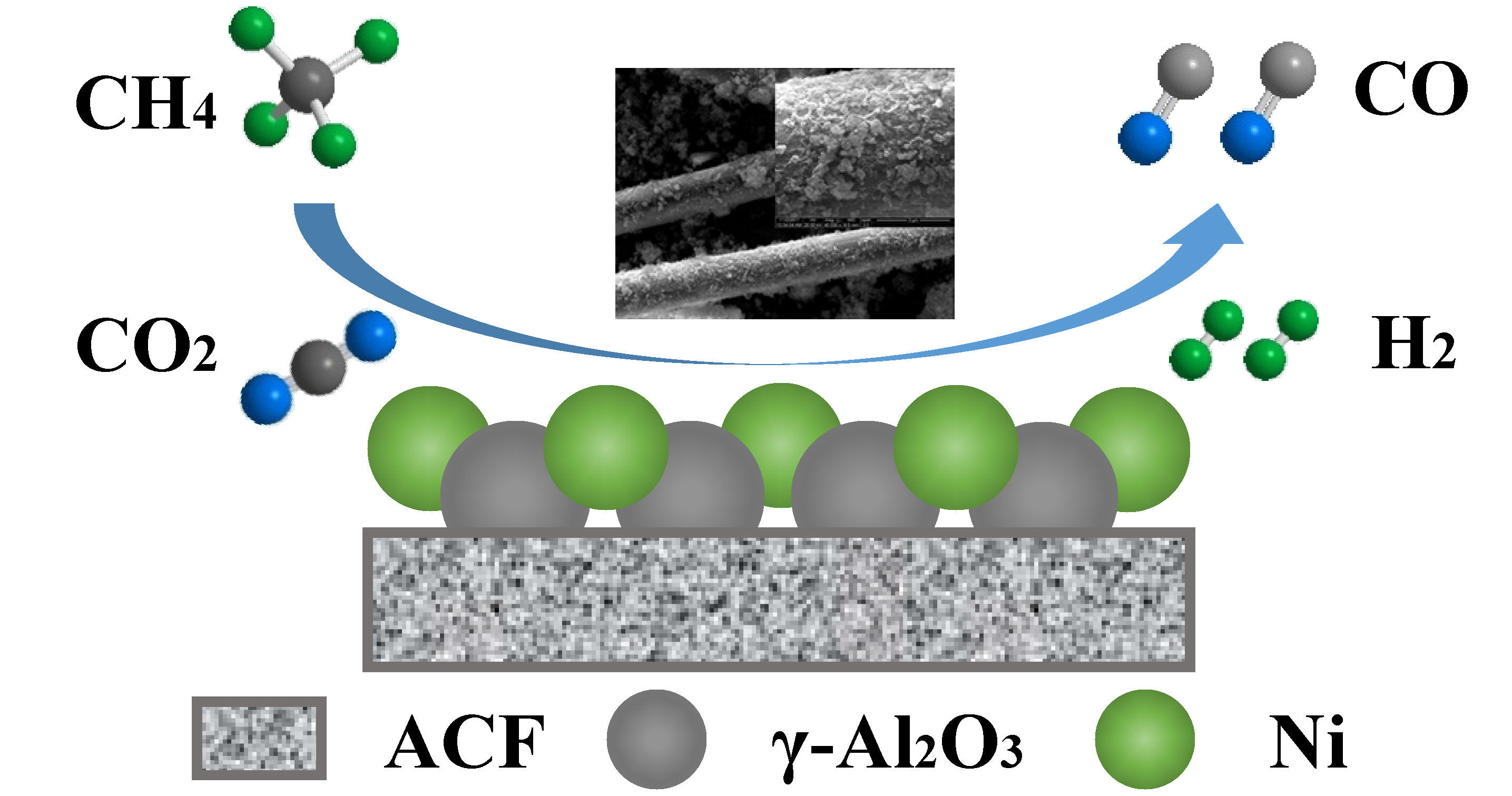
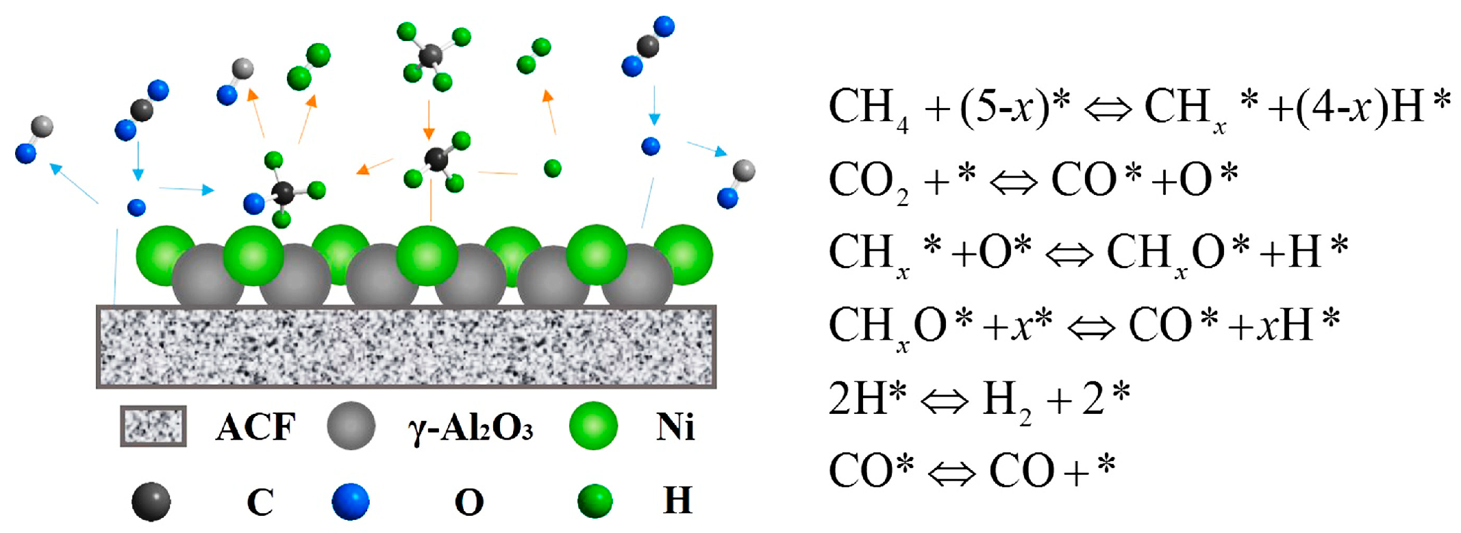
The relevant research about the mechanism of dry reforming shows that the CH4 activation (breaking of the C–H bond) favorably occurs on the Ni crystallites in the catalyst, while CO2 is preferentially adsorbed on the support [36]. For this study, CO2-TPD illustrated that the CO2 would be adsorbed on Al2O3 and ACF, respectively. The FTIR spectra reveals that the added ACF in the catalyst supports the abundant oxygen functional groups and methyl groups on the surface, which could be the intermediate product of dry reforming methane. So, based on the characterization results and the reaction steps of heterogeneous catalysis (adsorption–surface reaction–desorption), the dry reforming mechanism of catalyst Ni–γ–Al2O3/ACF (ACF:Al2O3 = 1:1) could be derived, as seen in Figure 8.
Generally, the adsorbed methane is activated by nickel, and is dissociated to release the CHX and H fragments. The carbon dioxide will be adsorbed by the supports (ACF or Al2O3), followed by activation. Then, the adsorbed CO2 will release the CO and O fragment. The CHX fragment combined with the O fragment will generate the CHXO fragment, then produce the CO and H fragment. The H fragment could merge to release H2.
3. Materials and Methods
3.1. Preparation of Catalyst
The coprecipitation method is applied for the catalyst preparation. The chopped polyacrylonitrile-based activated carbon fibers with around 100 meshes were selected to serve as the support. The solutions of aluminum nitrate, nickel nitrate, and sodium carbonate with different proportions were selected as the precursor of precipitant. The catalyst could be prepared by the following steps. Firstly, adding a certain amount of ACF into a beaker with 100 mL deionized water and stirring in a water bath at 40 °C. Then, the solutions of aluminum nitrate, nickel nitrate, and sodium carbonate with different proportions were added into that beaker by peristaltic pumps. The precipitant would be coprecipitated on the surface of the ACF, and was aged 30 min. Then, the filtered precipitant would be washed by deionized water, until the pH was neutral, and was then dried at 105 °C, followed with calcination for 2 h at 600 °C. Finally, the unreduced catalyst would be obtained. A series of nickel-based catalysts were configured, with different mass ratios of γ–Al2O3 to ACF, ranging from 0:10 to 10:0. Based on our former research [28], the optimum mass content of Ni for all of the catalysts is 5%.
3.2. Catalysts Evaluation
The catalytic performance of the different catalysts was evaluated in a fixed bed reactor, as shown in Figure S3. Before the reaction, the catalysts would be reduced in a hydrogen atmosphere of 50 mL/min at 650 °C for 2 h. Then, 0.5 g of the catalyst was loaded in a vertical tubular furnace, whose inner diameter is 8 mm. The nitrogen was selected as the carrier gas. The produced gas was collected by a gas bag of 500 mL for analysis, after first being dried by silica gel.
In order to better reflect the catalytic performance, some parameters have been defined. The CH4 conversion ratio is defined as Equation (1), as follows:
where is the CH4 flow rate in the feed gas, and is the CH4 flow rate in the out products.
The CO2 conversion ratio is defined as Equation (2), as follows:
where is the CO2 flow rate in the feed gas, and is the CO2 flow rate in the out products.
The H2 selectivity and CO selectivity is defined as Equations (3) and (4), as follows:
where is the H2 flow rate in the out products.
The carbon equilibrium in gas phase before and after reaction is defined as Equation (5), as follows:
where is the CO flow rate in the out products.
3.3. Catalyst Characterization and Product Analysis
The gas composition was analyzed by a gas chromatograph (GC5890N, Kejie Co., Ltd., Nanjing, China) equipped with a thermal conductivity detector (TCD) and a flame ionization detector (FID). The chemisorption characterizations (H2-TPR, H2-TPD, and CO2-TPD) (FineSorb3010, Finetec Co., Ltd., Hengzhou, China) were conducted to illustrate the interaction between the active metal and the support, metal dispersion, and the surface basic sites, respectively. A field emission scanning electron microscopy (SEM) (FEI Inspect F50, Thermo Fisher Scientific, Waltham, MA, USA) was applied to investigate the surface topography of the prepared catalysts. Furthermore, the various functional groups on the catalyst’s surface were illustrated by FTIR spectra (Nicolet-6700, Thermo Fisher Scientific, Waltham, MA, USA). The XRD (Smart lab 3, Rigaku, Tokyo, Japan) was applied to investigate the crystal structure of the prepared catalysts. A specific surface area and pore size analyzer (V-Sorb 2800P, Gold APP Instruments Corporation, Beijing, China) was applied to obtain the specific surface area and pore structure parameters.
4. Conclusions
In this study, Ni and Al2O3 were coprecipitated on ACF in order to obtain various catalysts with a different ratio of Al2O3 to ACF, used for DRM. Some conclusions could be drawn as follows. The optimum ratio of Al2O3 to ACF is 5:5. The added ACF in the catalyst Ni/γ–Al2O3/ACF is beneficial for the catalytic activity in DRM, especially for the conversion of CO2 at different temperatures. The coprecipitated coating of Ni and Al2O3 on the ACF surface proved by SEM could restrain the carbon of the ACF from participating in reforming, while retaining the good surface properties of the fibers. Furthermore, the chemisorption characterization results (H2-TPD, H2-TPR, and CO2-TPD) revealed that adding ACF into a nickel-based catalyst could enhance the basic sites and improve the metal dispersion on the catalyst surface, which is beneficial for the adsorption and activation of feed gas. The XRD patterns illustrated that adding ACF into the catalyst Ni–Al2O3 could decrease the crystallite size of the spinel NiAl2O4, which is beneficial for methane reforming. In addition, the FTIR spectra of different catalysts revealed that the added ACF in the catalyst could provide abundant oxygen functional groups and methyl groups on the surface, which could be the intermediate product of DRM, and effectively promote the reaction.
Supplementary Materials
The following are available online at https://www.mdpi.com/2073-4344/8/12/658/s1: Figure S1: Catalytic performance with different ratio of ACF to γ-Al2O3; Figure S2: EDS of the catalysts Ni-γ-Al2O3/ACF; Figure S3: Peak analysis of H2-TPR result of the catalyst Ni-γ-Al2O3/ACF; Figure S4: Schematic diagram of experimental apparatus for DRM; Table S1: specific surface area and pore structure parameters of two catalysts (Ni/γ–Al2O3, Ni–Al2O3/ACF); Table S2: Fitting results.
Author Contributions
Conceptualization, L.Y. and M.S.; methodology, L.Y.; validation, M.S.; investigation, L.Y. and Y.W.; resources, M.S.; data curation, L.Y.; writing—original draft preparation, L.Y.; writing (review and editing), L.Y., M.S., and J.X.; project administration, M.S.; funding acquisition, M.S.
Funding
This research was funded by the National Natural Science Foundation of China (grant number 51576048), the Fundamental Research Funds for the Central Universities, and the Postgraduate Research and Practice Innovation Program of Jiangsu Province (grant number KYCX17_0082).
Conflicts of Interest
The authors declare no conflict of interest. The funders had no role in the design of the study; in the collection, analyses, or interpretation of data; in the writing of the manuscript; or in the decision to publish the results
References
- Li, D.; Li, R.; Lu, M.; Lin, X.; Zhan, Y.; Jiang, L. Carbon dioxide reforming of methane over Ru catalysts supported on Mg-Al oxides: A highly dispersed and stable Ru/Mg(Al)O catalyst. Appl. Catal. B-Environ. 2017, 200, 566–577. [Google Scholar] [CrossRef]
- Khavarian, M.; Chai, S.; Mohamed, A.R. The effects of process parameters on carbon dioxide reforming of methane over Co-Mo-MgO/MWCNTs nanocomposite catalysts. Fuel 2015, 158, 129–138. [Google Scholar] [CrossRef]
- Fan, C.; Zhu, Y.A.; Yang, M.L.; Sui, Z.J.; Zhou, X.G.; Chen, D. Density functional theory-assisted microkinetic analysis of methane dry reforming on Ni catalyst. Ind. Eng. Chem. Res. 2015, 54, 5901–5913. [Google Scholar] [CrossRef]
- Daza, C.E.; Moreno, S.; Molina, R. Co-precipitated Ni-Mg-Al catalysts containing Ce for CO2 reforming of methane. Int. J. Hydrog. Energy 2011, 36, 3886–3894. [Google Scholar] [CrossRef]
- Zhang, X.; Yang, C.; Zhang, Y.; Xu, Y.; Shang, S.; Yin, Y. Ni-Co catalyst derived from layered double hydroxides for dry reforming of methane. Int. J. Hydrog. Energy 2015, 40, 16115–16126. [Google Scholar] [CrossRef]
- Rogers, J.L.; Mangarella, M.C.; D’Amico, A.D.; Gallagher, J.R.; Dutzer, M.R.; Stavitski, E.; Miller, J.T.; Sievers, C. Differences in the Nature of Active Sites for Methane Dry Reforming and Methane Steam Reforming over Nickel Aluminate Catalysts. ACS Catal. 2016, 6, 5873–5886. [Google Scholar] [CrossRef]
- Lertwittayanon, K.; Youravong, W.; Lau, W.J. Enhanced catalytic performance of Ni/α-Al2O3 catalyst modified with CaZrO3 nanoparticles in steam-methane reforming. Int. J. Hydrog. Energy 2017, 42, 28254–28265. [Google Scholar] [CrossRef]
- Yao, L.; Galvez, M.E.; Hu, C.; Costa, P.D. Mo-promoted Ni/Al2O3 catalyst for dry reforming of methane. Int. J. Hydrog. Energy 2017, 42, 23500–23507. [Google Scholar] [CrossRef]
- Sepehri, S.; Rezaei, M. Ce promoting effect on the activity and coke formation of Ni catalysts supported on mesoporous nanocrystalline γ-Al2O3 in autothermal reforming of methane. Int. J. Hydrog. Energy 2017, 42, 11130–11138. [Google Scholar] [CrossRef]
- Wang, S.; Lu, G.Q.; Millar, G.J. Carbon Dioxide Reforming of Methane to Produce Synthesis Gas over Metal-Supported Catalysts: State of the Art. Energy Fuels 1996, 10, 896–904. [Google Scholar] [CrossRef]
- Meshkani, F.; Rezaei, M. Nanocrystalline MgO supported nickel-based bimetallic catalysts for carbon dioxide reforming. Int. J. Hydrog. Energy 2010, 35, 10295–10301. [Google Scholar] [CrossRef]
- Bachiller-Baeza, B.; Mateos-Pedrero, C.; Soria, M.A.; Guerrero-Ruiz, A.; Rodemerck, U.; Rodríguez-Ramos, I. Transient studies of low-temperature dry reforming of methane over Ni-CaO-ZrO2-La2O3. Appl. Catal. B-Environ. 2013, 129, 450–459. [Google Scholar] [CrossRef]
- Nair, M.M.; Kaliaguine, S.; Kleitz, F. Coke resistant nanostructured Ni/La2O3 catalyst for dry reforming of methane. High Surface Area Mesoporous Perovskites for Catalytic Applications. ACS Catal. 2014, 4, 3837–3846. [Google Scholar] [CrossRef]
- Zhang, L.; Zhang, Q.; Liu, Y.; Zhang, Y. Dry reforming of methane over Ni/MgO-Al2O3 catalysts prepared by two-step hydrothermal method. Appl. Surf. Sci. 2016, 389, 25–33. [Google Scholar] [CrossRef]
- Alipour, Z.; Rezaei, M.; Meshkani, F. Effect of alkaline earth promoters (MgO, CaO, and BaO) on the activity and coke formation of Ni catalysts supported on nanocrystalline Al2O3 in dry reforming of methane. J. Ind. Eng. Chem. 2014, 20, 2858–2863. [Google Scholar] [CrossRef]
- Singha, R.K.; Yadav, A.; Agrawal, A.; Shukla, A.; Adak, S.; Sasaki, T.; Bal, R. Synthesis of highly coke resistant Ni nanoparticles supported MgO/ZnO catalyst for reforming of methane with carbon dioxide. Appl. Catal. B-Environ. 2016, 191, 165–178. [Google Scholar] [CrossRef]
- Liu, Z.; Grinter, D.C.; Lustemberg, P.G.; Nguyen-Phan, T.D.; Zhou, Y.; Luo, S.; Waluyo, I.; Crumlin, E.J.; Stacchiola, D.J.; Zhou, J.; et al. Dry Reforming of Methane on a Highly-Active Ni-CeO2 Catalyst: Effects of Metal-Support Interactions on C-H Bond Breaking. Angew. Chem. Int. Ed. 2016, 55, 7455–7459. [Google Scholar] [CrossRef] [PubMed]
- He, D.; Luo, Y.; Tao, Y.; Strezov, V.; Nelson, P.; Jiang, Y. Promoter Effects on Nickel-Supported Magnesium Oxide Catalysts for the Carbon Dioxide Reforming of Methane. Energy Fuels 2017, 31, 2353–2359. [Google Scholar] [CrossRef]
- Van Keulen, A.N.J.; Seshan, K.; Hoebink, J.H.B.J.; Ross, J.R.H. TAP Investigations of the CO2 Reforming of CH4 over Pt/ZrO2. J. Catal. 1997, 166, 306–314. [Google Scholar] [CrossRef]
- Song, M.; Zhang, W.; Chen, Y.; Luo, J.; John, C.C. The preparation and performance of lignin-based activated carbon fiber adsorbents for treating gaseous streams. Front. Chem. Sci. Eng. 2017, 11, 328–337. [Google Scholar] [CrossRef]
- Song, M.; Yu, L.; Wang, K.; Jin, B. The preparation and adsorption performance of sewage sludge based carbon adsorbents by one step fluidized bed pyrolysis methods. Fresenius Environ. Bull. 2017, 26, 1883-U4. [Google Scholar]
- Tang, X.; Song, M.; Yu, L.; Wang, X. Comparison and application of different component municipal solid wastes based carbon on adsorption of carbon dioxide. Int. J. Green Energy 2017, 14, 135–140. [Google Scholar] [CrossRef]
- Song, Q.; Xiao, R.; Li, Y.; Shen, L. Catalytic carbon dioxide reforming of methane to synthesis gas over activated carbon catalyst. Ind. Eng. Chem. Res. 2008, 47, 4349–4357. [Google Scholar] [CrossRef]
- Zhang, Y.; Zhang, G.; Zhang, B.; Guo, F.; Sun, Y. Effects of pressure on CO2 reforming of CH4 over carbonaceous catalyst. Chem. Eng. J. 2011, 173, 592–597. [Google Scholar] [CrossRef]
- Bradford, M.C.; Vannice, M.A. CO2 reforming of CH4 over supported Ru catalysts. J. Catal. 1999, 183, 69–75. [Google Scholar] [CrossRef]
- Ferreira-Aparicio, P.; Marquez-Alvarez, C.; Rodrıguez-Ramos, I.; Schuurman, Y.; Guerrero-Ruiz, A.; Mirodatos, C. A transient kinetic study of the carbon dioxide reforming of methane over supported Ru catalysts. J. Catal. 1999, 184, 202–212. [Google Scholar] [CrossRef]
- Wei, Y.; Song, M.; Yu, L.; Tang, X. Preparation of ZnO-Loaded Lignin-Based Carbon Fiber for the Electrocatalytic Oxidation of Hydroquinone. Catalysts 2017, 7, 180. [Google Scholar] [CrossRef]
- Yu, L.; Song, M.; Gao, R.; Wei, Y. Preparation and application of nickel based carbon fibers for the steam reforming of methane. React. Kinet. Mech. Catl. 2017, 120, 477–488. [Google Scholar] [CrossRef]
- Frontera, P.; Aloise, A.; Macario, A.; Antonucci, P.L.; Crea, F.; Giordano, G.; Nagy, J.B. Bimetallic Zeolite Catalyst for CO2 Reforming of Methane. Top. Catal. 2010, 53, 265–272. [Google Scholar] [CrossRef]
- Tantis, I.; Dozzi, M.V.; Bettini, L.G.; Chiarello, G.L.; Dracopoulos, V.; Selli, E.; Lianos, P. Highly functional titania nanoparticles produced by flame spray pyrolysis. Photoelectrochemical and solar cell applications. Appl. Catal. B-Environ. 2016, 182, 369–374. [Google Scholar] [CrossRef]
- Ma, Y.; Yan, C.; Xu, H.; Liu, D.; Shi, P.; Zhu, Y.; Liu, J. Enhanced interfacial properties of carbon fiber reinforced polyamide 6 composites by grafting graphene oxide onto fiber surface. Appl. Surf. Sci. 2018, 452, 286–298. [Google Scholar] [CrossRef]
- Chen, H.; Cai, Q.; Wu, J.; Xia, X.; Liu, H.; Luo, Z. Interfacial enhancement of carbon fiber/nylon 12 composites by grafting nylon 6 to the surface of carbon fiber. Appl. Surf. Sci. 2018, 441, 538–545. [Google Scholar]
- Fei, J.; Duan, X.; Luo, L.; Zhang, C.; Qi, Y.; Li, H.; Feng, Y.; Huang, J. Grafting methyl acrylic onto carbon fiber via Diels-Alder reaction for excellent mechanical and tribological properties of phenolic composites. Appl. Surf. Sci. 2018, 433, 349–357. [Google Scholar] [CrossRef]
- Ruiz-Rosas, R.; Bedia, J.; Lallave, M.; Loscertales, I.G.; Barrero, A.; Rodríguez-Mirasol, J.; Cordero, T. The production of submicron diameter carbon fibers by the electrospinning of lignin. Carbon 2010, 48, 696–705. [Google Scholar] [CrossRef]
- Li, L.; Zhang, L.; Shi, X.; Zhang, Y.; Li, J. Carbon dioxide reforming of methane over nickel catalysts supported on mesoporous MgO. J. Porous Mater. 2014, 21, 217–224. [Google Scholar] [CrossRef]
- Pakhare, D.; Spivey, J. A review of dry (CO2) reforming of methane over noble metal catalysts. Chem. Soc. Rev. 2014, 43, 7813–7837. [Google Scholar] [CrossRef] [PubMed]
Figure 1.
SEM of the catalysts: (a) activated carbon fibers (ACF); (b) Ni–γ–Al2O3; (c) Ni–γ–Al2O3/ACF.
Figure 1.
SEM of the catalysts: (a) activated carbon fibers (ACF); (b) Ni–γ–Al2O3; (c) Ni–γ–Al2O3/ACF.

Figure 2.
Chemisorption characterizations for different catalysts (a) H2-temperature programmed reduction (H2-TPR); (b) H2-temperature programmed desorption (H2-TPD); (c) CO2-temperature programmed desorption (CO2-TPD).
Figure 2.
Chemisorption characterizations for different catalysts (a) H2-temperature programmed reduction (H2-TPR); (b) H2-temperature programmed desorption (H2-TPD); (c) CO2-temperature programmed desorption (CO2-TPD).
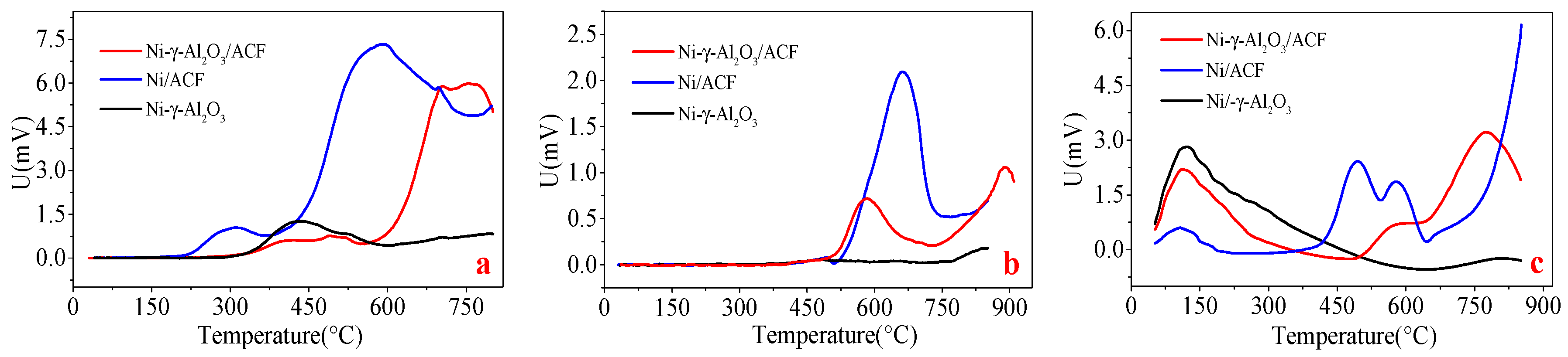
Figure 3.
XRD patterns for ACF, Ni–Al2O3, and Ni–Al2O3/ACF (JCPDS cards no. 75-1621, 74-1081, and 71-1179).
Figure 3.
XRD patterns for ACF, Ni–Al2O3, and Ni–Al2O3/ACF (JCPDS cards no. 75-1621, 74-1081, and 71-1179).

Figure 4.
Fourier transform infrared spectroscopy (FTIR) spectra of ACF and catalyst of Ni–Al2O3/ACF.
Figure 4.
Fourier transform infrared spectroscopy (FTIR) spectra of ACF and catalyst of Ni–Al2O3/ACF.

Figure 5.
Catalyst stability test (a: CH4 conversion ratio; b: CO2 conversion ratio). Gas hourly space velocity (GHSV): 24,000 mL·h−1·g−1; detailed reaction conditions: CH4: 50 mL/min; CO2: 50 mL/min; N2: 100 mL/min; catalyst dosage: 0.5 g; temperature: 750 °C; test time: 900 min.
Figure 5.
Catalyst stability test (a: CH4 conversion ratio; b: CO2 conversion ratio). Gas hourly space velocity (GHSV): 24,000 mL·h−1·g−1; detailed reaction conditions: CH4: 50 mL/min; CO2: 50 mL/min; N2: 100 mL/min; catalyst dosage: 0.5 g; temperature: 750 °C; test time: 900 min.

Figure 6.
Calculation of carbon equilibrium. GHSV: 24,000 mL·h−1·g−1; detailed reaction conditions: CH4: 50 mL/min; CO2: 50 mL/min; N2: 100 mL/min; catalyst dosage: 0.5 g; temperature: 750 °C; test time: 900 min.
Figure 6.
Calculation of carbon equilibrium. GHSV: 24,000 mL·h−1·g−1; detailed reaction conditions: CH4: 50 mL/min; CO2: 50 mL/min; N2: 100 mL/min; catalyst dosage: 0.5 g; temperature: 750 °C; test time: 900 min.

Figure 7.
Catalytic activity at different temperatures (a: CH4 conversion ratio; b: CO2 conversion ratio; c: H2 selectivity; d: CO selectivity). GHSV: 24,000 mL·h−1·g−1; detailed reaction conditions: CH4: 50 mL/min; CO2: 50 mL/min; N2: 100 mL/min; catalyst dosage: 0.5 g.
Figure 7.
Catalytic activity at different temperatures (a: CH4 conversion ratio; b: CO2 conversion ratio; c: H2 selectivity; d: CO selectivity). GHSV: 24,000 mL·h−1·g−1; detailed reaction conditions: CH4: 50 mL/min; CO2: 50 mL/min; N2: 100 mL/min; catalyst dosage: 0.5 g.

Figure 8.
Schematic of elementary reaction of dioxide reforming of methane (DRM) with Ni–γ–Al2O3/ACF.
Figure 8.
Schematic of elementary reaction of dioxide reforming of methane (DRM) with Ni–γ–Al2O3/ACF.


Table 1.
Crystallite size of spinel for Ni–Al2O3 and Ni–Al2O3/ACF.
| Samples | 2-Theta (°) | FWHM (°) | Crystallite Size of NiAl2O4 (nm) | Average Crystallite Size of NiAl2O4 (nm) |
|---|---|---|---|---|
| 5% Ni–Al2O3 | 37.16 | 0.898 | 9.333 | 10.5 |
| 45.279 | 0.749 | 11.492 | ||
| 66.7 | 0.894 | 10.638 | ||
| 5% Ni–Al2O3/ACF | 37.381 | 0.873 | 9.607 | 9.1 |
| 45.086 | 1.018 | 8.449 | ||
| 66.482 | 1.036 | 9.168 |
FWHM: full width at half maxima.
© 2018 by the authors. Licensee MDPI, Basel, Switzerland. This article is an open access article distributed under the terms and conditions of the Creative Commons Attribution (CC BY) license (http://creativecommons.org/licenses/by/4.0/).
Share and Cite
MDPI and ACS Style
Yu, L.; Song, M.; Wei, Y.; Xiao, J. Combining Carbon Fibers with Ni/γ–Al2O3 Used for Syngas Production: Part A: Preparation and Evaluation of Complex Carrier Catalysts. Catalysts 2018, 8, 658. https://doi.org/10.3390/catal8120658
AMA Style
Yu L, Song M, Wei Y, Xiao J. Combining Carbon Fibers with Ni/γ–Al2O3 Used for Syngas Production: Part A: Preparation and Evaluation of Complex Carrier Catalysts. Catalysts. 2018; 8(12):658. https://doi.org/10.3390/catal8120658
Chicago/Turabian StyleYu, Lei, Min Song, Yuexing Wei, and Jun Xiao. 2018. "Combining Carbon Fibers with Ni/γ–Al2O3 Used for Syngas Production: Part A: Preparation and Evaluation of Complex Carrier Catalysts" Catalysts 8, no. 12: 658. https://doi.org/10.3390/catal8120658
Note that from the first issue of 2016, this journal uses article numbers instead of page numbers. See further details here.