Article

Metal Oxide Nanoparticles Supported on Macro-Mesoporous Aluminosilicates for Catalytic Steam Gasification of Heavy Oil Fractions for On-Site Upgrading

1
Grupo de Investigación en Fenómenos de Superficie–Michael Polanyi, Facultad de Minas, Universidad Nacional de Colombia Sede-Medellín. Kra 80 No. 65-223 Medellín, Colombia
2
Grupo de Investigación Industrial en Diseño de Materiales a partir de Minerales y Procesos (IDIMAP), Sumicol S.A.S., Sabaneta, 055450, Colombia
*
Authors to whom correspondence should be addressed.
Catalysts 2017, 7(11), 319; https://doi.org/10.3390/catal7110319
Submission received: 28 September 2017 / Revised: 16 October 2017 / Accepted: 16 October 2017 / Published: 29 October 2017
(This article belongs to the Special Issue Design Challenges for Catalytic and Photocatalytic Reactors)

Abstract

:
Catalytic steam gasification of extra-heavy oil (EHO) fractions was studied using functionalized aluminosilicates, with NiO, MoO3, and/or CoO nanoparticles with the aim of evaluating the synergistic effect between active phase and the support in heavy oil on-site upgrading. Catalysts were characterized by chemical composition through X-ray Fluorescence, surface area, and pore size distribution through N2 adsorption/desorption, catalyst acidity by temperature programmed desorption (TPD), and metal dispersion by pulse H2 chemisorption. Batch adsorption experiments and catalytic steam gasification of adsorbed heavy fractions was carried out by thermogravimetric analysis and were performed with heavy oil model solutions of asphaltenes and resins (R–A) in toluene. Effective activation energy estimation was used to determine the catalytic effect of the catalyst in steam gasification of Colombian EHO. Additionally, R–A decomposition under inert atmosphere was conducted for the evaluation of oil components reactions with active phases and steam atmosphere. The presence of a bimetallic active phase Inc.reases the decomposition of the heavy compounds at low temperature by an increase in the aliphatic chains decomposition and the dissociation of heteroatoms bonds. Also, coke formation after steam gasification process is reduced by the application of the bimetallic catalyst yielding a conversion greater than 93%.

1. Introduction

With the depletion of conventional sources of crude oil, heavy oil (HO) and extra heavy oil (EHO) became an important alternative for the oil and gas industry [1,2,3]. Alberta in Canada, the Orinoco belt between Colombia and Venezuela, as well as China, Russia, and Mexico are regions with the most important heavy oil resources [4,5]. In Colombia, the production of HO and EHO represents about 60% of the current oil production, and the key reserves are located in the Eastern Plains and the Middle Magdalena Valley areas with 9 and 1.7 billion barrels of estimated reserves respectively [6,7,8]. Due to the severe declining of light and medium oil reserves in Colombia, it is expected that the production of HO and EHO will constitute more than 90% of the Colombian production [6].
The HO and EHO production have technical and economic challenges related to its physical and chemical properties that make difficult the transport and processing of the oil [9,10]. The specific gravity of these fluids are from 10 to 20° of American petroleum institute gravity (API) for HO and lower than 10° API for EHO [9,11], and this is associated with the high content of heavy compounds such as resins and asphaltenes [12]. Asphaltenes self-association and functional groups with C–S and C=S bonds provide viscosities greater than 103 cP [11,13]. Additionally, due the low H/C ratio in the crude, and the appreciable content of heteroatoms (N, O, S) and metals (Fe, Ni, V), in refinery, at least 50 wt % of the HO and EHO correspond to vacuum residues with boiling points above 773 K [14,15].
Pipelining is the most convenient method for crude transportation and its derived products, but the supply of HO and EHO through pipelines involve high-pressure drops, clogging of the lines and multiphase flow formation [9,16]. Moreover, there are some pipeline requirements such a viscosity lower than 300 cSt at 303 K, API gravity higher than 18° API and a water content lower than 0.5% [17]. Consequently, the viability of HO and EHO production depends on the techniques used to increase the oil mobility through the pipeline. There are some alternatives such as the viscosity reduction based on the dilution with a lighter oil or a derivate, the formation of an oil-water emulsion, or increasing the system temperature to improve the HO and EHO properties [18].
Blending heavy oils with lighter oils, condensates or alcohols is the most used method for viscosity reduction [9,19,20]. Nevertheless, the use of a specific solvent is influenced by the compatibility of the fluids and the yield in the solvent recovery process [17]. The ratio of solvent in the mixture ranges from 20 to 40 vol % to avoid high pressure drops or the use of high temperatures through the pipeline [9,17,21]. The increase in the transport volume due the dilution of the HO or EHO requires pipelines with a larger diameter and the growth of the supplied energy by pumps [9]. Also, a solvent recovery process and the construction of a pipeline from the site of solvent recovery to the well are necessary [18,21]. The incompatibility of fluids could lead to the destabilization and precipitation of asphaltenes and paraffin, improving the clogging and the fouling of the pipeline and the equipment in the refinery [22,23,24,25]. Also, because the use of large amounts of solvent is necessary, the availability and the price fluctuations of solvent and crude oil make the economic viability of the technique rather difficult [26]. In this context, Colombia needs to import naphtha from Canada and the United States to dilute the produced heavy oils [27].
When the application of solvents for viscosity reduction is not available, the emulsification of the crude oil is an option to meet the pipeline specifications [28]. The stability and viscosity of the heavy crude oil in water emulsions (O/W) are affected by the surfactant concentration, mixing process, the pH and the salinity of the aqueous phase [29,30,31]. The required water amount to generate an O/W emulsion could be at least 50 vol %, and the surfactant necessary to keep the emulsion stable could impact the viscosity of the system [31]. The compatibility of the produced water and oil together with the availability of water near the wall, affect the application of this method [32]. The reduction of the friction between the pipeline and the heavy oil with the use of drag reducing additives or the generation of an annular and core flow is another approach for the heavy oil transport [9]. The drag reducing agents are surfactants, fibers or polymers that act like regime modifiers, trying to keep in laminar flow the oil transport [33,34,35].
Refining technologies related to physicochemical upgrading could be used to increase the API gravity, decrease the viscosity, the pollutants in the crude, and increase the value per barrel in the market [9,36]. Refining applications such as visbreaking coupled with in-situ techniques like the Steam-Assisted Gravity Drainage are commonly used in Canada’s bitumen upgrading [37,38]. Nevertheless, the synthetic crude conversion is a function of the heavy fraction composition, where the yield of light crude production means high coke production [39]. Many kinds of processes such as thermal cracking, catalytic cracking, hydrocracking and thermal catalytic steam gasification are methods proposed for the partial upgrading of the heavy oil and are based on the cracking of compounds with more than 30 molecules of carbon [40,41]. However, carbon residue deposition, catalyst deactivation due to the heavy metals content in the feedstock (such as Ni, V) are the most common problem related to heavy oil upgrading [42]. Consequently, the heavy oil upgrading on surface demands the development of catalyst with the ability to adsorb the heaviest fraction and then promote the cracking of adsorbed molecules with a low coke production [43].
The catalyst comprises an active phase preferably supported on a macro or mesoporous material [44]. Several researchers have reported the adsorptive behavior between the heavy oil fraction with carbon [45], clays [46,47,48], kaolin [49], silica [50], and alumina [51], López-Linares et al. [52] evaluated the visbroken residue and the asphaltenes adsorption on kaolin and clay, associating the high aromaticity and nitrogen content with the adsorptive behavior of the heavy fraction. Marriot et al. [53] suggested the hydrogen production based on the adsorption and gasification of the unstable heavy fraction during the visbreaking process with kaolin as the adsorbate. Due to the low cost of the mesoporous materials, textural properties modification like as pore size and surface area are used to improve the adsorptive capacity [54]. The active phase comprises metal oxides on the support surface, and there are mostly Ni, Mo, W and Co [44,55,56]. Nevertheless, the combination of those metals in the active phase could lead a better catalytic behavior [53,57]. Heavy fractions of Maya crude oil were converted to lighter products with an increase in the API gravity from 20.9 to 25.2 in a hydroprocessing process with the evaluation of CoMo/Al2O3 and NiMo/Al2O3 catalyst [58]. Also, alkali metals were investigated since their catalytic reactivity in the steam gasification of the asphaltenes in high with the following trend of reactivity Cs > Rb > K > Na > Li [59,60,61]. Other authors [41,62] have focused their efforts in the investigation of other oxide catalysts such as TiO2, Fe2O3, and ZrO2 due to the successful production of lighter fuels from atmospheric-distilled residual oil (AR) by catalytic cracking in a steam atmosphere.
The potential application of metal oxide nanoparticles as an alternative to the current techniques in heavy oil upgrading [63,64] could lead the employment of materials with different surface nature for heavy fractions adsorption and subsequent catalytic decomposition at relatively low temperatures [65]. In this sense, various commercial and synthesized metal oxides as Al2O3, SiO2, Fe3O4, Co3O4, TiO2, MgO, CaO, and NiO show high capacity and affinity for asphaltene adsorption and decomposition [66,67,68,69,70]. Researchers suggest NiO nanoparticles as the materials with the higher asphaltene adsorption activity with a significant decrease in the temperature and activation energy in the asphaltenes decomposition [71]. Ni–Pd bimetallic nanocatalysts supported on SiO2, TiO2 or Al2O3 nanoparticles for steam gasification of Colombian asphaltenes showed better results in asphaltene decomposition rather than the monometallic ones, and the non-functionalized supports [65,72]. Also, the same bimetallic nanocatalyst supported on SiO2 was evaluated in thermal decomposition of resin I and asphaltenes blend in oxidative atmosphere showing the catalytic activity of these materials in the heavy fraction decomposition [73].
Hassan et al. [43] observed that the adsorption and subsequent steam gasification of adsorbed asphaltenes could be improved by the incorporation of 3 wt % of NiO nanoparticles into mesoporous–macroporous metakaolin in comparison with the NiO-free metakaolin. The availability and reduced cost of mesoporous–macroporous materials as clay and kaolin, and its adsorptive affinity towards polar hydrocarbons is an object of interest in the application as supports of bimetallic nanocatalyst [59,74,75]. In this sense, the heavy oil upgrading on surface conditions require catalysts with high and stable activity through heavy oil decomposition in a steam atmosphere at high temperature, good resistance to coke, sulfur compounds, and heavy metals deposition [76].
In this context, the primary objective of this work is the evaluation of microparticulate materials, such as kaolin, and clay obtained from Colombian mineral resources functionalized with nanoparticles of NiO, MoO3, CoO and their combinations on the decomposition of heavy fractions of crude oil such as resins and asphaltenes. The decomposition of the heavy fractions of crude oils is achieved at relatively low temperatures aiming at the early upgrading of heavy and extra-heavy oils. Adsorption and subsequent catalytic steam gasification of both asphaltenes and resins is studied. A correlation between the adsorptive process and the catalytic activity of the nanoparticle-functionalized materials based on affinity, self-association of the adsorbate and effective activation energy is for the first time reported. The adsorption behavior of the crude oil heavy compounds was described by the solid–liquid equilibrium (SLE) model and was correlated with the catalytic activity of the synthesized materials. This work provides potential applications of nanoparticle technology for heavy oil processing and production, which could be a viable alternate green technology.

2. Results and Discussion

2.1. Catalyst Characterization

The chemical composition of fresh clay and metakaolin supports obtained from X-ray Fluorescence (XFR) is shown in Table 1. Compounds as SiO2 and Al2O3 are the main oxides presents in the supports structure, with a minor content of Fe2O3 and TiO2. Other oxides such, CaO, MgO, Na2O and BaO are present with contents <1 wt %. More than 80% of the content in both materials are SiO2 and Al2O3, with a similar SiO2 composition but with a difference of more than 10% of the Al2O3 content between both supports. In addition, from Table 1 it can be observed that the SiO2/Al2O3 ratios are 2.4 and 1.5 for Clay and Metakaolin, respectively.
Surface area (SBET) pore size distribution (PSD) of the materials were obtained through the N2 adsorption/desorption experiments, the results are listed in Table 2. The PSD of the virgin supports showed range of sizes corresponding to mesopores in the structure of the support for values between 20 to 100 Å [77]. For metakaolin, a bimodal behavior is observed with peaks at 39 and 27 Å. However, for clay a single peak is observed at 23 Å.
The TPD profile obtained with the adsorption/desorption of NH3 molecules in the samples gives information related to the type of acidity present in the sample based on the desorption peaks [78]. For aluminosilicates, the Al–OH and Si–OH functional groups are responsible for the NH3 adsorption [79,80]. TPD-NH3 profiles of ammonia desorption for clay, metakaolin, and their functionalization are shown in Figure 1 and results of total acidity are listed in Table 2. From Figure 1 two predominant peaks at 590 K and 845 K for fresh clay can be observed due to the presence of Lewis and Brønsted sites [79,81]. The low-temperature peak observed in a TPD profile is related to the Lewis sites. Furthermore, the high-temperature peak is associated with the Brønsted sites, because the energy required to promote the NH3 desorption is higher [80]. In the case of metakaolin, the thermal process in the material preparation could contribute to the collapse of the layers in its structure, hindering the diffusion of the NH3 in the sample. Hence, it can be said that clay structure presents a high contribution of the acidity for the acid sites inside the material through an easier NH3 diffusion. It can be observed a reduction of the total acidity for the clay-supported catalysts after the metal oxide impregnation, and this could be due to the pores blockage by the metal oxide formation, decreasing the NH3 diffusion and adsorption through the clay structure. Also, when comparing Ni-containing materials, higher acidity values are observed and is in agreement with Peña et al. [82] who evaluated the supported metal oxide (Mn, Cu, Cr, Co, Fe, V, and Ni) in TiO2 for catalytic reduction of NO with NH3 and observed that TiO2-Ni catalyst offers a higher acidity in comparison with the Co supported catalyst.
Pulse H2 chemisorption measured the covered metal surface after functionalization process to identify the formation of metal oxide nanoparticles troughs the H2 consumption. Results of the metal oxide mean particle size for the studied samples is shown in Table 2. For this metal combinations, the alloy formation is expected between the different evaluated active phases [83,84,85], and the results of mean particle size and the dispersion degree are based on the cluster size and dispersion degree of the alloy formed. The obtained results confirm the formation of metal oxide nanoparticles over the support surface. It can be observed from Table 2 that mean particle size for compounds synthesized over the clay surface have an average value of 4.5 nm, while for the KMoNi and KMoCo samples the mean particles sizes are higher with values of 8.9 and 13.5 nm, respectively. Hence, it can be said that the formation of the oxide nanoparticles over the material surface may be influenced by the porous structure of the material. Dispersion of the active material over the support surface was about 10% for clay and between 15% and 20% for metakaolin.

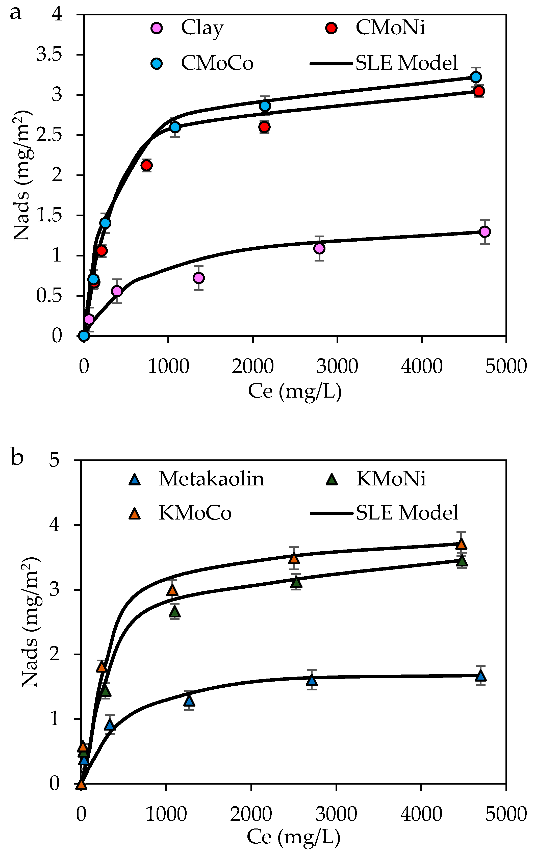
2.2. Adsorption Isotherms of Resins and Asphaltenes

Due to the high molecular weight of the heavy fractions compounds, the diffusion of these molecules through the pores in a porous material is low [43]. For this reason, textural properties such the volume and pore diameter are more important in the heavy fraction adsorption than the specific surface area of the material [52]. Furthermore, adsorption isotherms of R–A are shown in Figure 2a,b for (a) clay-supported and (b) metakaolin-supported catalysts together with the SLE model fit. In accordance with the International Union of Pure and Applied Chemistry (IUPAC), the obtained adsorption isotherms follow a Type Ib behavior, which means a strong interaction between the available active zones in the adsorbent and the R–A mixture [77,86,87]. However, the asphaltenes–resins interactions and a lower amount of functional groups, as well as low polarity in resins structure, could affect the interactions between the adsorbent and adsorbate [69,88,89]. The low asphaltenes concentration and the colloidal state of the adsorbate affects the asphaltene–asphaltene interactions, indicating that the adsorption process could be governed by the interaction of the adsorbent with the asphaltene-surrounding resins [25,89]. A heterogeneous adsorbent with multiple selectivities for heavy fraction would be more efficient attracting the heavy compounds to the catalyst surface. In this sense, the MoCo catalysts show the highest adsorptive capacity of the heavy fraction for both clay and metakaolin supports. The selectivity towards the active phase generates an improvement in the self-association (i.e., K parameter of the SLE model) of the heavy oil fraction over the catalyst surface and follows the trend KMoCo > KNiMo > CMoCo > KNiMo > Metakaolin > Clay. A suitable catalyst for the heavy fraction adsorption by longer pores and higher surface acidity results in a better adsorptive behavior. In addition, a higher acidity in the active sites generates an improvement in the affinity between the adsorbate and the adsorbent, showing a reduction in the H parameter. For a better comprehension of the adsorption process, the experimental data was described by the SLE model [90]. The values of the obtained model parameters and their associated R2 and Root Mean Square Error (RSME%) values are shown in Table 3.
For KNiMo material, a higher total acidity could lead a strong adsorption process, due to the relation between the adsorption affinity (i.e., H lower) and the total acidity reported in Table 2. Franco et al. [68] and Nassar et al. [69] showed that relationship exists between the surface acidity and the adsorption capacity of asphaltenes. Attraction forces between the O- and N-containing functional groups of the heavy fraction with active sites available for the adsorption process is expected to be an important adsorption mechanism [91,92]. The high clay acidity is associated with a better diffusion of NH3 molecules through the pores of the particle due to their low particle diameter [93]. However, the available acid sites for heavy fraction adsorption is less, due to the aggregates formed in the R–A systems that decrease the diffusion capacity through the porous materials. It has been reported that the addition of resins to asphaltene solutions changes the self-aggregation of the asphaltenes [94]. The stabilization effect of resins has been attributed to form smaller structures preventing the flocculation of the asphaltenes particles [95,96]. Spiecker et al. [97] found that with an R–A ratio of about 10:1 in toluene solutions, R–A aggregates correlated a length between 11–14 Å. This indicates that the active acid sites where the adsorption could happen are less than the total acid sites of the particle. In this sense, a surface impregnation with the metals leads to active sites that are more available for R–A adsorption.

2.3. Catalytic Steam Gasification of Heavy Fractions

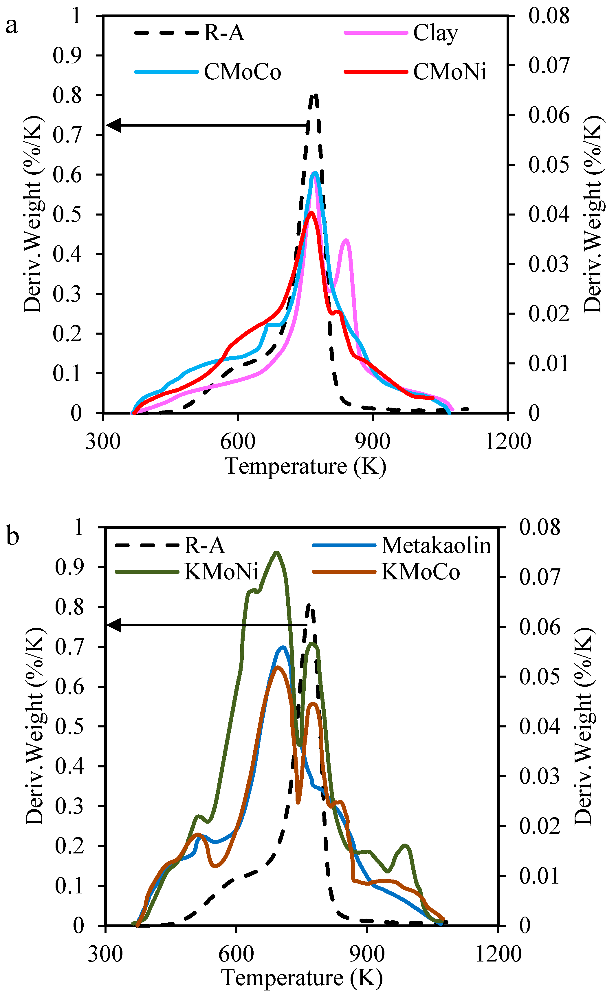
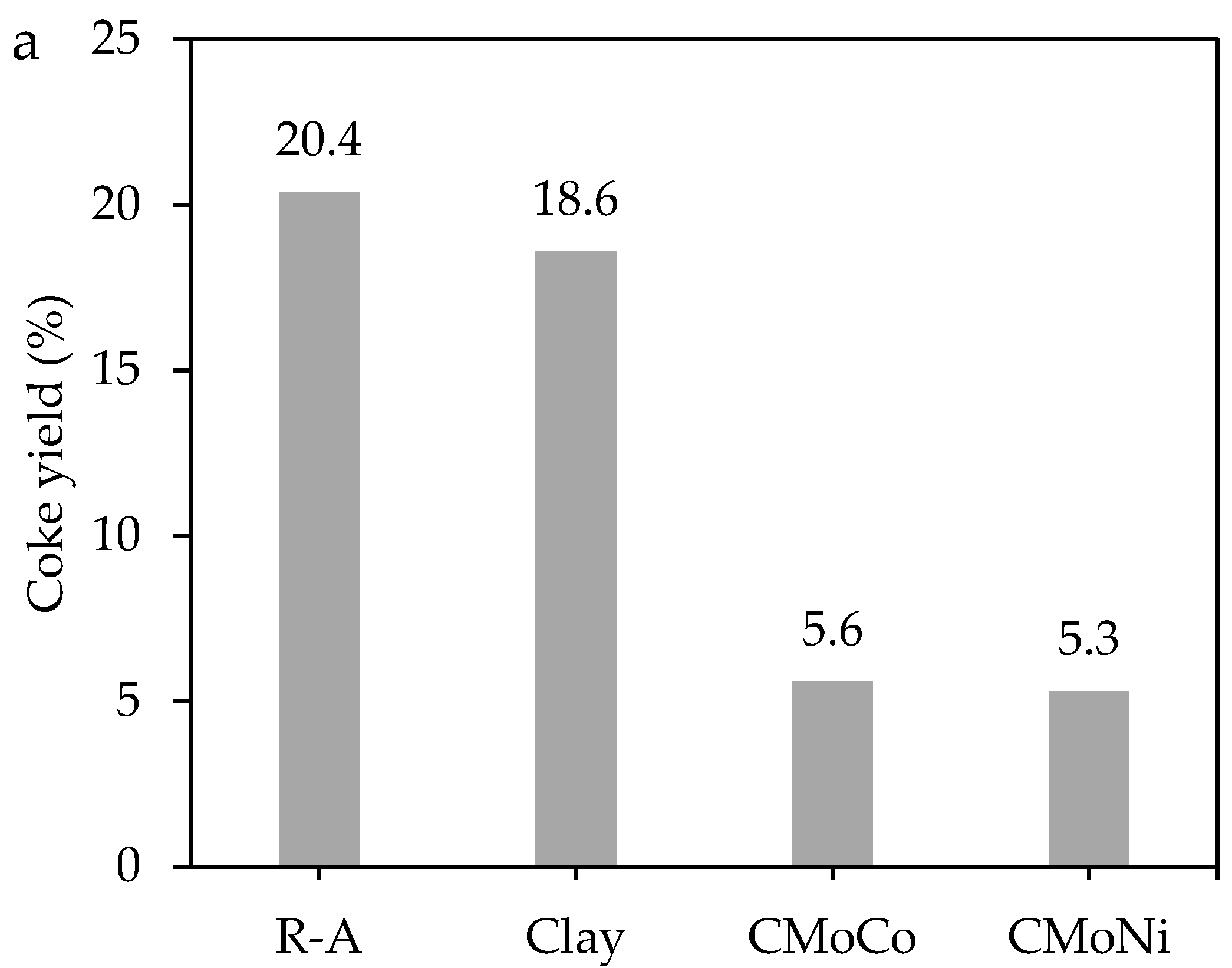
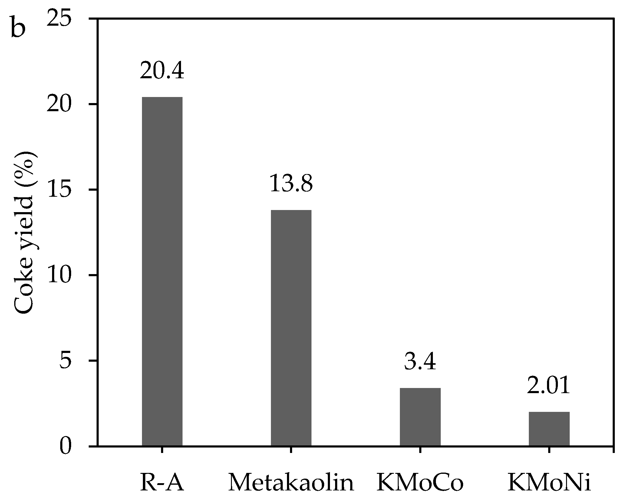
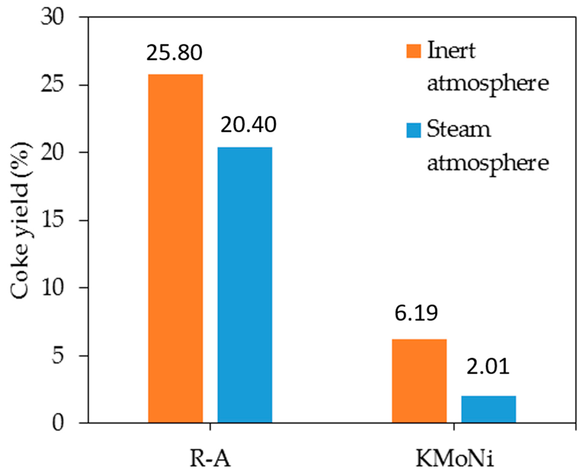
2.3.1. Mass Loss Analysis

The catalytic steam gasification tests of the heavy fraction in the presence and absence of the catalysts were performed in an N2 atmosphere saturated with H2O(g). Figure 3 shows the plots of rate of mass loss for catalytic steam gasification in the presence and absence of (a) clay and (b) metakaolin-supported materials. Two characteristic zones can be observed for the rate of mass loss for the R–A mixture, and are associated with the aliphatic chains and aromatic rings decomposition in both heavy fractions [25]. From the asphaltenes and resins structure, it is supposed that R–A blend presents a higher aliphatic chains proportion than the aromatic rings, because of a low asphaltenes content. For lower temperatures (before 700 K), alkyl chains break up and dissociation of S–C and N–C bonds of the surrounded aliphatic chains in the micelle structure is expected [25,98,99]. R–A decomposition begins at approximately 470 K in the absence of the materials and is reduced about 100 K in the presence of the catalysts associated with an enhancement of the functionalized supports in the aliphatic chains decomposition for both active phases [7]. Hence, metakaolin surface contribution generates a synergetic effect in the R–A steam gasification in comparison with the results observed for functionalized clay. The main decomposition peak for R–A mixture is observed at 773 K, which is attributed to aromatics rings decomposition [13]. However, in the presence of the synthesized metakaolin-supported catalysts, this temperature can be reduced significantly, probably related to the chemical content (Al2O3 and SiO2) and the pore size distribution that could determine the interaction degree of the adsorbed species and the adsorbate. Metakaolin bimetallic catalysts reduce the R–A main peak decomposition more than 100 K, with a clear contribution of both active phases. KMoNi profile present 3 main decompositions peaks instead of the KMoCo series, which presents 2 decompositions peaks. The main decomposition peak for R–A in presence of KMoNi is observed at 695 K and 707 K for KMoCo. The magnitude of the mass changes as a function of temperature at 500 K is higher for KMoNi than KMoCo catalyst, suggesting a higher rupture of short and long alkyl groups for KMoNi sample [7]. It could be inferred that peak observed at 780 K would be due to the presence of MoO3 nanoparticles in the decomposition test of the MoNi and MoCo series, nevertheless, a higher magnitude in KMoNi decomposition profile propose a better synergistic effect between Mo–Ni than Mo–Co in the polycyclic aromatics hydrocarbons cracking [72]. For this reason, the behavior differences between the magnitudes of the decomposition profile of the adsorbed R–A species in MoNi- and MoCo-containing materials could be associated such a higher catalytic activity of the MoNi couple. NiO nanoparticles present in the MoNi series enhanced the catalytic behavior of a Mo bimetallic catalyst for heavy fractions decomposition as a result of a high acidity in comparison with MoCo series.
The R–A decomposition in the presence and absence of KMoNi sample under an inert atmosphere is shown in Figure 4. The KMoNi catalyst under inert atmosphere enhances the R–A cracking at lower temperatures by the presence of active sites which catalyzes the chains rupture [100]. Virgin R–A decomposition begins at 545 K and 485 K for pyrolysis and steam gasification process respectively, which suggests that the steam atmosphere improve the short and long chain rupture by the saturation and partial oxidation of the molecules [101]. For steam gasification, water catalytic dissociation products are used for organic free radicals saturation and oxidation/reforming reactions [59]. At lower temperatures, a higher profile magnitude for steam gasification of adsorbed R–A onto KMoNi, which suggest the formation of free radical saturations and reforming reactions with the short and longs chains of the surrounding aromatics rings in R–A species. Differences between the KMoNi profiles in steam and inert atmosphere in the high-temperature zone suggest that NiO nanoparticles in presence of steam minimize the condensation of free radicals by the addition of hydrogen in the radicals structures [102].
After the steam gasification process, the coke formation was evaluated by heating the samples in an oxidative atmosphere at a flow of 100 mL/min and a heating rate of 20 K/min. Conversion degree of the R–A mixture in the absence and presence of the catalysts is shown in Figure 5 for (a) clay and (b) metakaolin-supported materials. Heavy oil fractions conversion was enhanced by the presence of metal oxide nanoparticles as active phase of the materials, remaining the following coke trend for R–A steam gasification: R–A (18.6%) > Clay (20.4%) > Metakaolin (13.8%) > CMoCo (5.6%) > CMoNi (5.3%) > KMoCo (3.4%) > KMoNi (2.1%). The results suggest that the evaluated bimetallic catalyst promote a low coke yield, enhance the conversion of the heavy compounds at low temperatures and reduce the feasibility of deactivation by the coke presence on the catalyst surface.
Figure 6 shows the coke yield for virgin and adsorbed R–A on KMoNi surface under steam and inert atmospheres. Steam injection as a source of hydrogen allows the coke yield reduction for virgin and adsorbed R–A by the saturation and reforming of free radicals obtained fom thermal cracking [59]. In this sense, for inert atmosphere the coke yield of virgin and adsorbed R–A is 25.8% and 6.19%. Nevertheless, coke yield under steam atmosphere for virgin and adsorbed R–A is 20.4% and 2.01%.

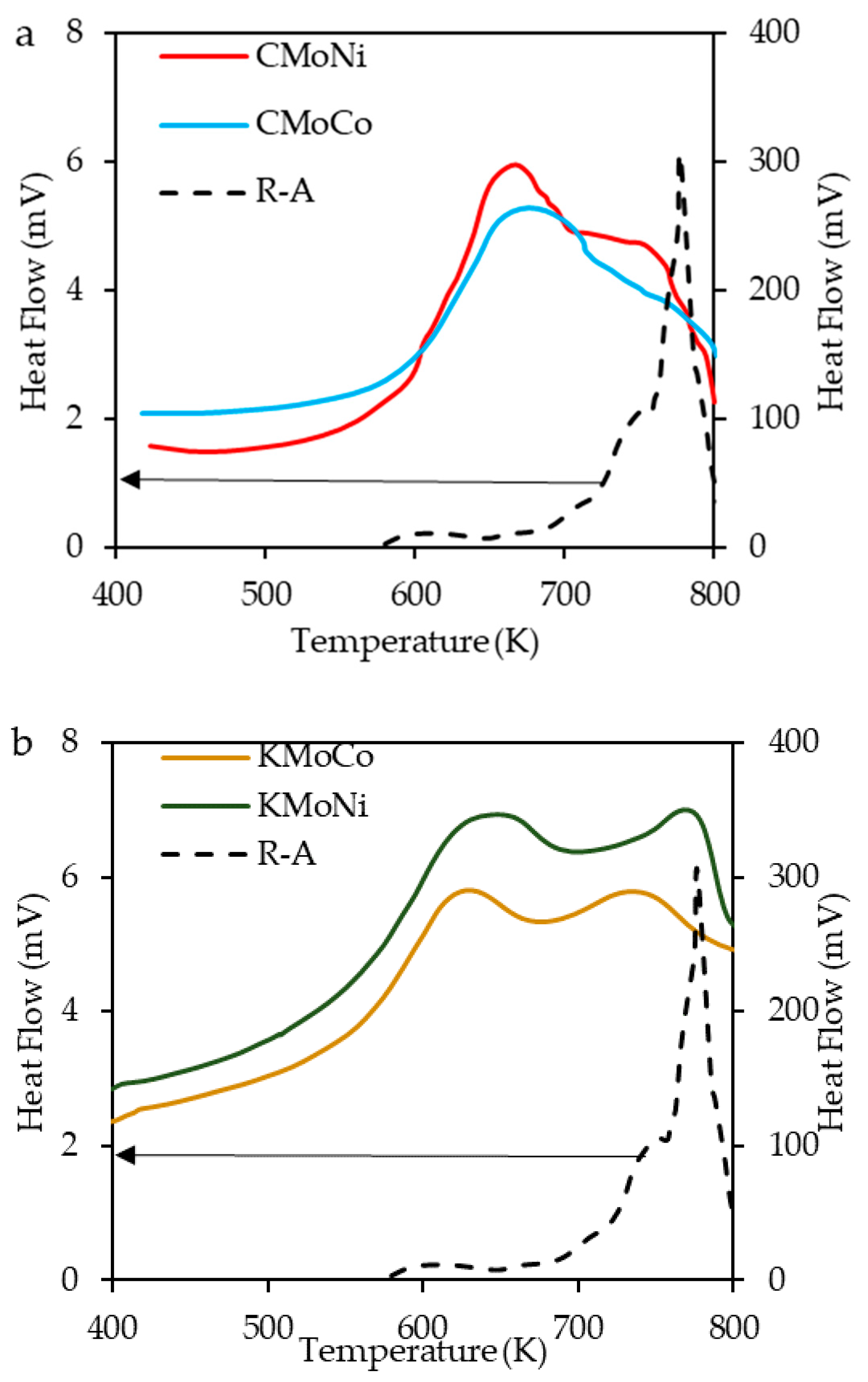
2.3.2. Differential Scanning Calorimetry (DSC) Analysis

Differential scanning calorimetry (DSC) experiments under air atmosphere were carried out for the adsorbed R–A on the bimetallic catalyst surface and represented in Figure 7, with the aim to identify the reactions zones in the R–A decomposition. The catalytic behavior of supported clay catalyst is denoted by an exothermic reaction for temperatures below to 700 K, indicating the enhancement of the aliphatic chains decomposition. Two characteristics peaks on the heat flow are observed during the decomposition of adsorbed species in the presence of the catalysts with metakaolin as support, with similar results as the profile mass loss, representative to a high aliphatic and aromatic rings decomposition.

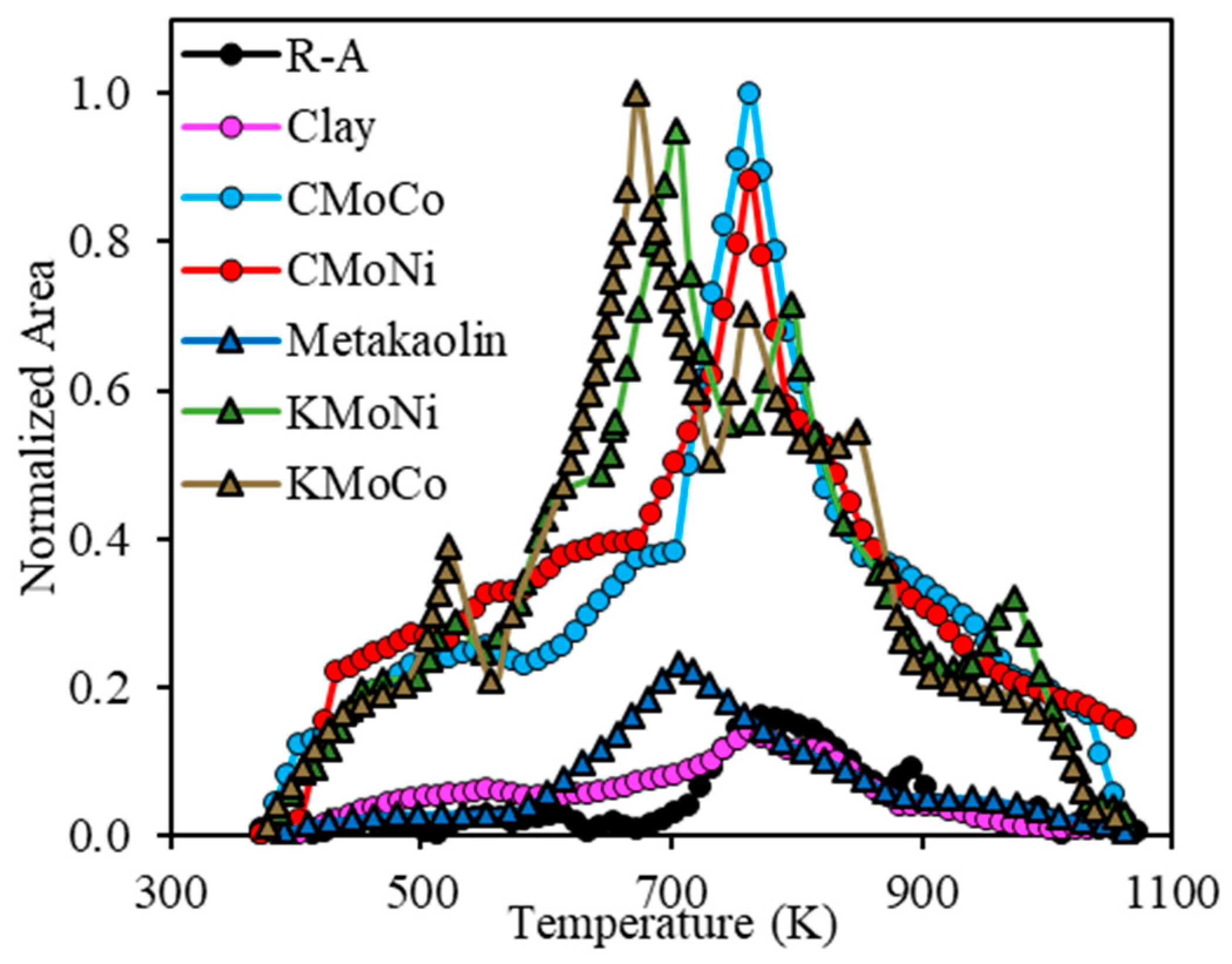
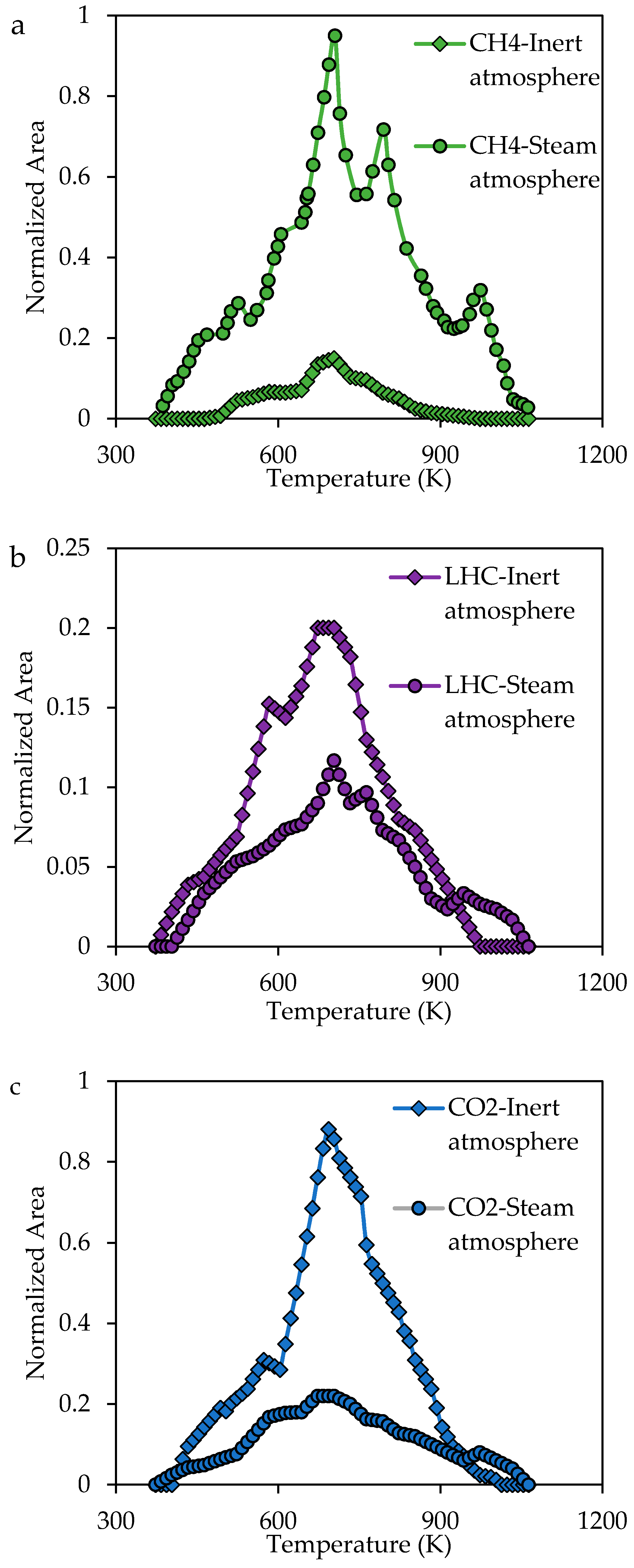
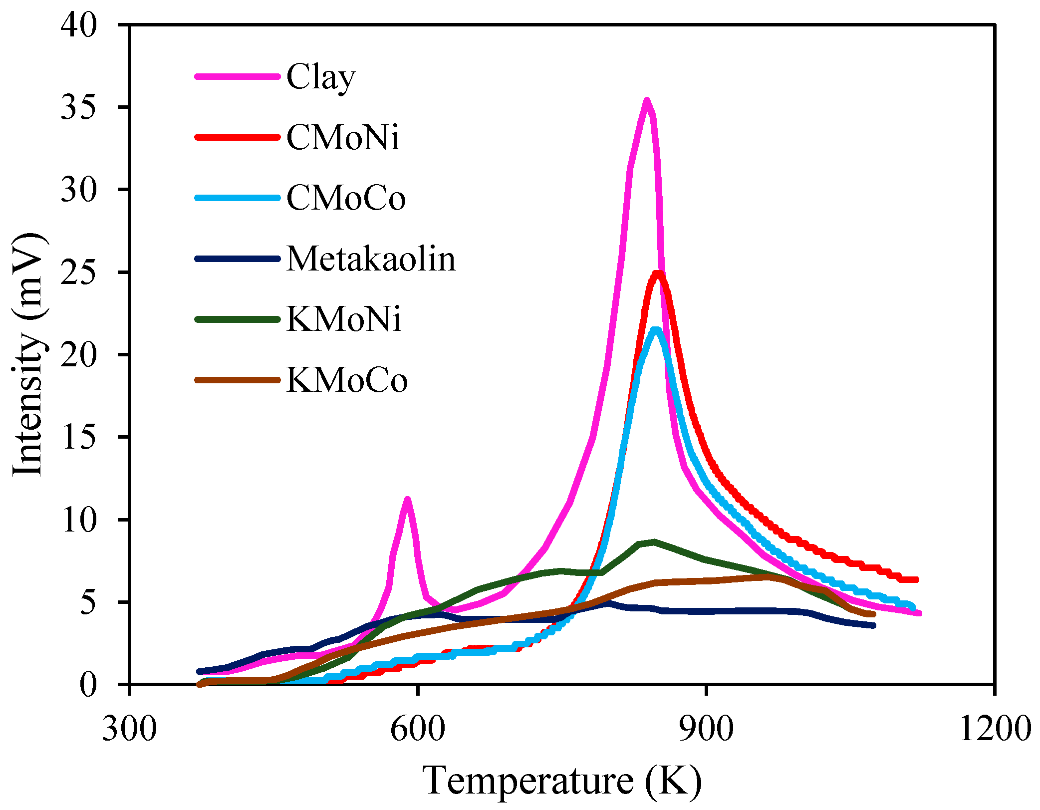
2.3.3. Analysis of the Evolution of the Gaseous Product during the Steam Gasification Process

The selectivity behavior during the catalytic process was studied by tracing the produced gasses using FTIR analysis [72,100,103]. Steam gasification of R–A fractions as carbonaceous source contains reactions such as water-gas shift reaction, partial oxidation, steam reforming reactions, boundary equilibrium reaction and methanation [72]. Different gasses could be involved in R–A decomposition, namely CO, CH4, O2, CO2 and H2. Nevertheless, H2 and O2 were eliminated for the present study, because of water signal interference [7]. Similarly, CO2 production was low in comparison with that of CH4. The CH4 production during the R–A gasification in the presence and absence of nanomaterials are shown in Figure 8. Because the CH4 band intensity for metakaolin bimetallic catalysts was always higher than the intensity reported in the others systems, the results were normalized based on the CH4 produced by the presence of KMoNi. The CH4 production by the steam gasification of the adsorbed heavy fraction compounds in the virgin supports does not show an increase in light hydrocarbons conversion, suggesting a low selectivity of the evaluated aluminosilicates in the methanation reaction [104]. The CH4 production is lower for clay support in comparison with the metakaolin material, probably due to a suitable structure that endorses the interaction between the active sites and the heavy fractions. However, supports functionalization process enhanced the CH4 production by the presence of different active sites, confirming the catalytic activity of the functionalized catalysts. Metal oxide nanoparticles guarantee a high CH4 production at lower temperatures [100], also promote the R–A conversion into light products with the following trend KMoCo < KMoNi < CMoCo < CMoNi < K < R–A < C. Partial oxidation, water-gas and steam reforming are associated with CO production, however, the evolution profile does not show a representative CO production in the evaluated catalyst, suggesting the promotion of the methanation reaction.
Evolution profiles of light hydrocarbons (LCH), CO2, CO and CH4 for R–A decomposition in presence of KMoNi under inert and steam atmospheres are shown in Figure 9. Panels (a) and (b) in Figure 9 show the CH4 and LHC production profiles under inert and steam atmosphere and panel (c) in Figure 9 displays the CO2 profiles under both atmospheres. Under inert atmosphere R–A is converted mainly to CO2, light hydrocarbons, and CH4 with a less extent. Also, oxygen sources present on catalyst structure and R–A functional groups are probably used in CO2 production during the thermal cracking by the reaction of free carbon radicals and the oxygen sources [13]. From Figure 9a,b it is observed that steam injection has hydrogen source contribute to a less condensation of light hydrocarbons by the cracking of LCH and saturation of free radicals [59], which means a higher yield in methane production under steam atmosphere. Carbon oxides profiles from Figure 9 shows a higher CO2 production under inert atmosphere instead of the CO2 production under steam atmosphere, suggesting that steam atmosphere improve the methanation of carbon oxides produced in reactions such partial oxidation, steam reforming and water–gas shift reactions [59,72].

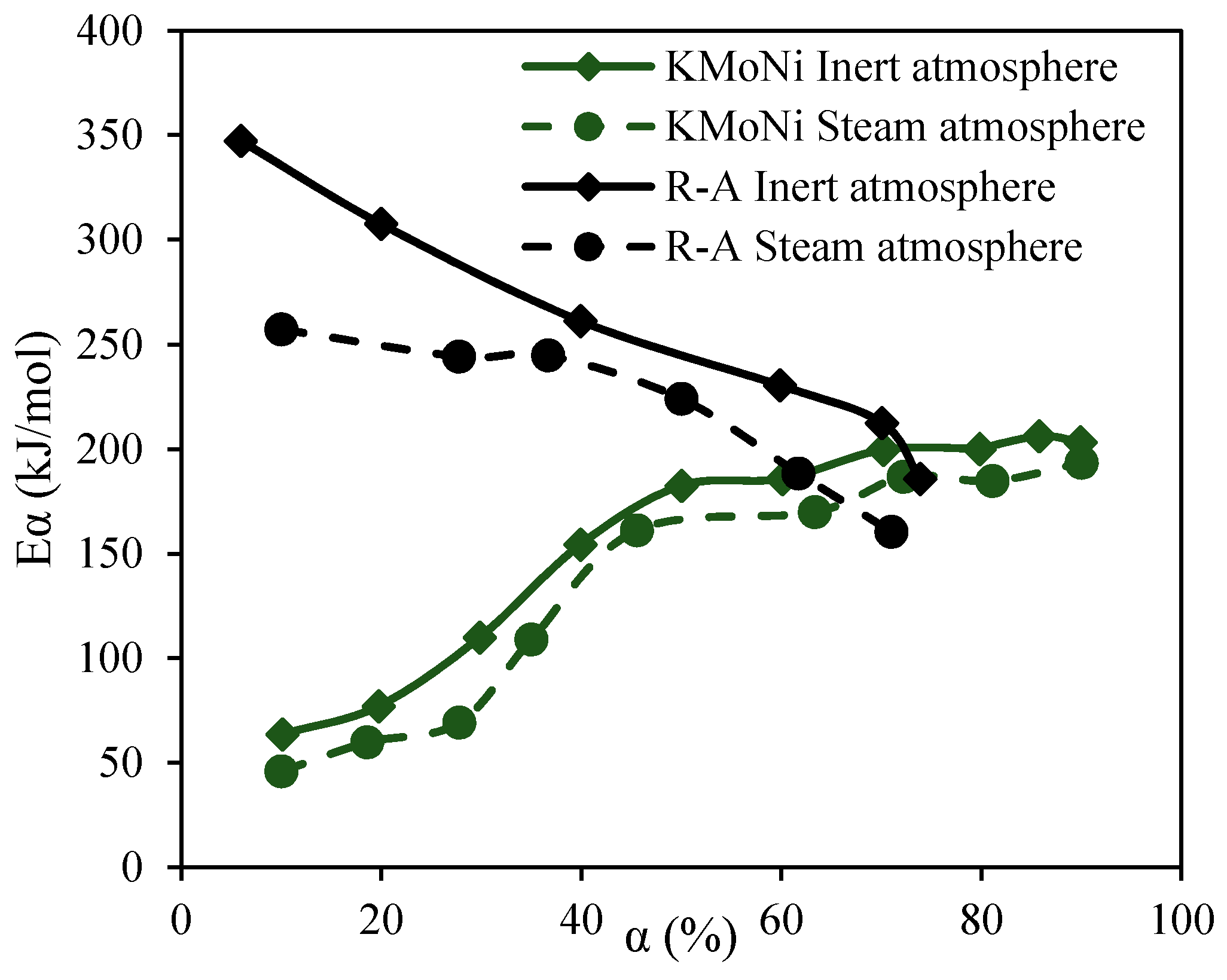
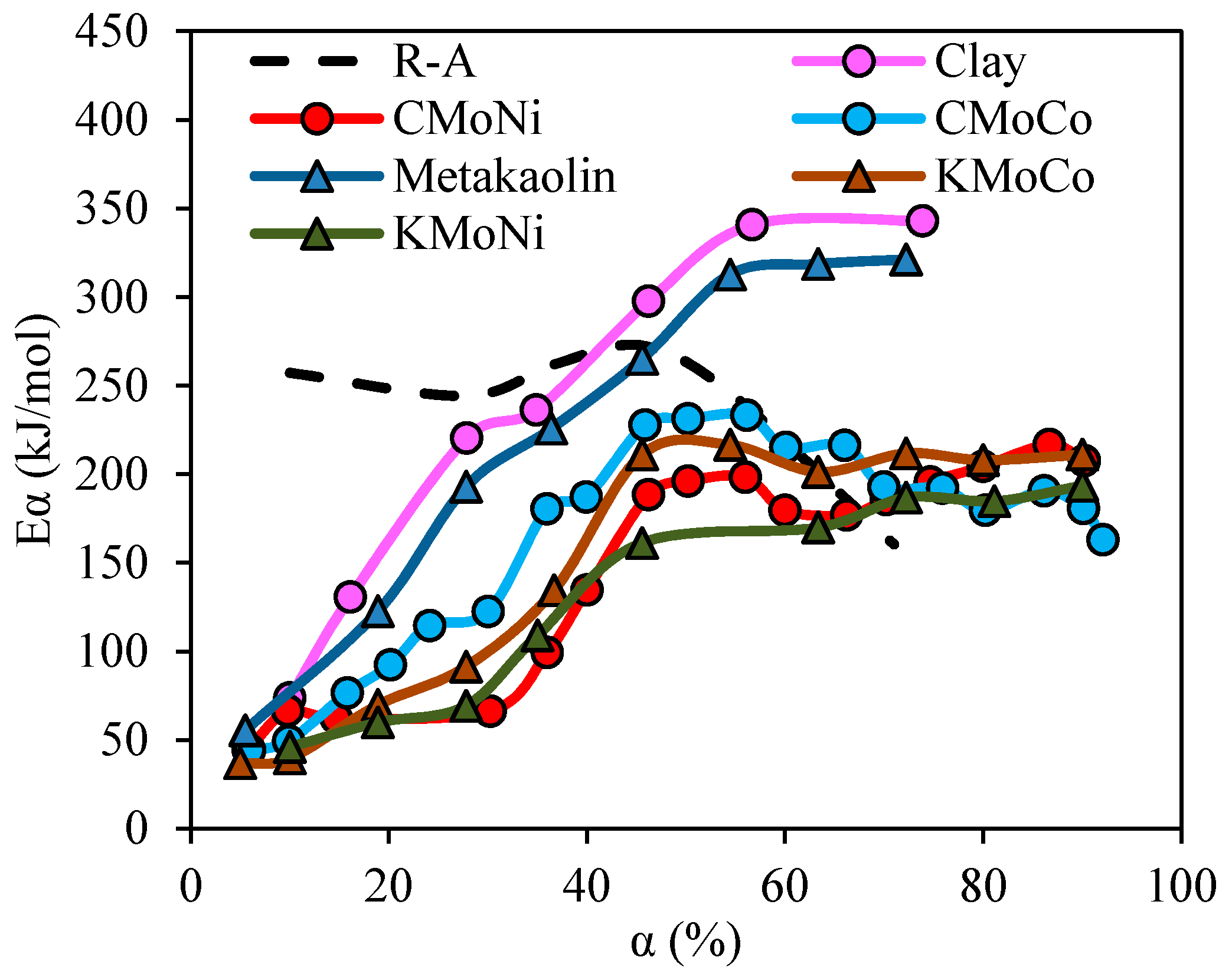
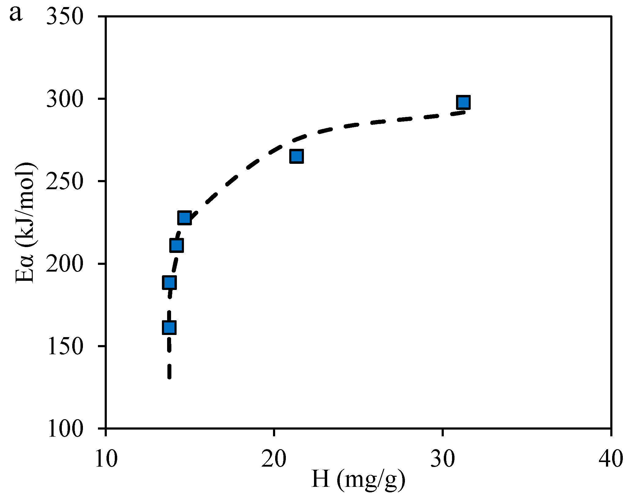
2.3.4. Effective Activation Energies

Effective activation energy (Eα) was calculated using isoconversional OFW method by thermogravimetric measurements at three different heating rates between 10 and 30 K/min to validate the catalytic activity of the evaluated catalysts. Figure 10 shows the estimated effective activation energies as a function of the conversion degree. R–A effective activation energies decreased as the conversion increase, while the Eα value for adsorbed R–A has the opposite trend. In virgin supports, for a conversion degree lower than 40%, the required energy is lowered in comparison with R–A compounds. The interaction between small aggregates adsorbed onto support surface is the first step in steam gasification of adsorbed species, requiring low amounts of energy. However, the decomposition of bigger aggregates and new compounds from addition reactions generates an increase in the activation energy required, suggesting the weakness of the active sites on the support surface in the gasification of heavy fractions compounds. In this sense, metakaolin supports exhibit a decrease in activation energy in all the conversion range in comparison with clay support, probably due to more available active sites from a higher pore size distribution and greater dispersion of the active phase over the support surface. Functionalized catalysts show reductions greater than 20% in the effective activation energy estimation for all the samples. Differences between the activation energy of MoNi- and MoCo-containing materials are associated with a higher affinity (lower H) between the R–A compounds and the MoNi-containing materials observed during the adsorption process, which lead a lower activation energy than MoCo-containing materials.
Figure 11 displays the estimated effective activation energy for virgin and adsorbed R–A onto KMoNi for steam and inert atmospheres. The activation energy required for virgin R–A decomposition at α = 60% is reduced 18% by the steam injection. Furthermore, the activation energy for adsorbed R–A fraction onto KMoNi surface at steam atmosphere is 10% less than the inert atmosphere. Steam injection as hydrogen source promote hydrocarbon steam gasification reactions, which reduce the coke formation, the estimated activation energy by the OFW method and enhance the production of valuable gases as CH4.
The comparison between adsorptive and catalytic behavior is presented in Figure 12a–c. Figure 12a suggest a relationship between H parameter for SLE model with the activation energy required for the decomposition of the heavy fractions, whereas a suitable support structure contributes to the reduction of the energy required after the functionalization process. Hence, it can be said that there is a synergistic effect between the active phases and the supports in the catalytic steam gasification of the adsorbed compounds. The presence of active phases with different selectivities improves the R–A aggregation at the primary active site, but also contribute in a heavy fraction cracking by the improvement in the catalyst affinity as observed in Figure 12b. For this reason, evaluated bimetallic catalyst exhibits and improvement in the aggregate adsorption with available active sites for reaction and subsequently heavy fractions decomposition into lighter products.

3. Materials and Methods

3.1. Materials and Chemical

Kaolin and clay microparticles with 10 µm and 2 µm in mean particle size, respectively, were provided by Suministros de Colombia (Sumicol S.A.S.) and were used as supports of the active phase. The kaolin was first calcinated at 1073 K yielding a Metakaolin support. Salt precursors, Ni(NO3)2·(6H2O) (Merck KGaA, Darmstadt, Germany), (NH4)6Mo7O24 (Merck KGaA, Darmstadt, Germany) and CoCl2 (J.T Baker, USA), as well as distilled water, were used for functionalization of the supports [105,106]. Toluene (99.5%, Merk KGaA, Darmstadt, Germany) was used to prepare heavy oil model solutions. An extra heavy crude oil, produced from a reservoir in the center of Colombia was the source of the heavy oil compounds used in this work. This crude oil has 6.4° API (with a specific gravity of 0.9745), the viscosity of 6 × 10⁶ at 298 K and contents of saturates, aromatics, resins, and asphaltenes of 19.2, 16.2, 52.0 and 12.6 wt %, respectively. Also, almost the 51 wt % of the crude has normal boiling point greater than 573 K. For resins and asphaltenes isolation, the extra-heavy crude oil was mixed with n-heptane (99%, Sigma-Aldrich, St. Louis, MO, USA) in a ratio of 40 mL of n-heptane per 1 g of crude oil. The solution was sonicated for 2 h and then stirred for 20 h at 200 rpm. Later, the mixture was centrifuged for 45 min at 4500 rpm and asphaltenes were recovered by filtration [107]. The deasphalted oil (DAO) obtained from asphaltenes extraction process was mixed with chromatographic silica (Sigma-Aldrich, St. Louis, MO, USA) in a 1:1 mass ratio and further stirred at 300 rpm for 24 h for separating the resins. The silica is filtered from the solution and then added to a Chloroform (Sigma-Aldrich, St. Louis, MO, USA) solution in a ratio of 10 mL per gram of crude for the purpose to generate the resins desorption [108,109]. The solution was stirred for 24 h at 200 rpm and then centrifuged for 45 min at 4500 rpm. Finally, the supernatant was evaporated and the resins were obtained.

3.2. Catalyst Preparation

The supports were first dried at 393 K for 6 h to eliminate any humidity, and impregnated using an aqueous solution based on the desired precursor salts. The salt precursors concentration in the aqueous solution used for the impregnation was achieved at a metal oxide content from 2.5 wt % for each metal on the catalyst surface. For this, Mo-Ni and Mo-Co combinations were employed for clay and metakaolin functionalization. The solid was calcined at 450 °C for 1 h, yielding an oxide catalyst [110]. The supported catalysts obtained in this study are denoted by the initial letter of the support and the symbols of the cations of the resulting metal oxides after calcination. For instance, the material CNiMo is a catalyst impregnated with 2.5 wt % of Ni and 2.5 wt % of Mo supported in clay and the material KMoCo is a catalyst impregnated with 2.5 wt % of Mo and 2.5 wt % of Co supported in metakaolin.

3.3. Catalyst Characterization

The virgin supports were analyzed using X-ray Fluorescence (XFR) analysis with a Rigaku spectrometer, equipped with a graphite monochromator using CuKα radiation (40 kV) and angular domain scanned 6° ≤ 2θ ≤ 70°. N2 adsorption and desorption experiments at 77 K were conducted in an Autosorb-1 from Quantachrome after outgassing samples overnight at 413 K. The surface area of the materials was calculated using the Brunauer–Emmett–Teller (BET) method [111], and the pore size distribution curves were obtained from desorption isotherms by the Barret–Joyner–Halenda (BJH) method [112]. Temperature programmed desorption with NH3 (TPD-NH3) experiments were performed to measure the total acidity of the prepared catalyst with the aim to correlate the surface acidity with the catalytic behavior in the decomposition tests. Approximately 100 mg of each prepared catalyst was dried at 473 K for 1 h under He flow in a U-shaped quartz tube. Then, a fixed amount of 10 vol % NH3 in He at 80 mL/min was introduced to be adsorbed at 373 K for 1 h. The carrying gas was changed again to pure He at 80 mL/min at 373 K for 1 h and finally heated up to 1143 K at 10 K/min [72]. A calibrated Thermal conductivity detector (TCD) with a constant flow of He at 80 mL/min senses the changes in the flow of the gas through the instrument, due to the desorption of the NH3 in the heating ramp [80,113]. The instrument used to TPD-NH3 experiments was a Chembet 3000 (Quantachrome Instruments, Boynton Beach, FL, USA). The determination of metal dispersion and average metal particles sizes in supported catalyst were performed by pulse chemisorption using H2 titration with the Chembet 3000 (Quantachrome Instruments, Boynton Beach, FL, USA). About 100 mg of the samples were placed in a U-shaped quartz tube dried at 473 K for 1 h. Then, the catalysts were reduced at 973 K for 1 h in 10 vol % H2 in Ar at 80 mL/min and purged with flowing Ar for 1 h until the samples reach atmosphere temperature (298 K). Hydrogen pulses continued until no additional uptake of H2 was observed. Due to the interactions between the metals on the support surface, the formation of alloys generates different adsorption behaviors between each of the components and their mixtures. For this reason, average metal particles sizes and metal dispersion are related to the bimetallic cluster formed in the support surface [83,84,85].

3.4. Batch Adsorption Experiments

According to the SARA heavy fraction content (asphaltenes and resins) in the extra heavy oil, the asphaltenes and resins have a mass ratio corresponding to 20:80 respectively in the oil matrix. Hence, batch adsorption experiments were performed at 298 K for different concentrations of a 20:80 mixture of resins and asphaltenes (R–A). The R–A mixtures were added in toluene at concentrations from 100 to 5000 mg/L and for a ratio of the solution volume to the dry mass of catalyst of 10 g/L [114]. The solutions were stirred for 24 h to ensure the maximum adsorption of the heavy compounds. Finally, the catalysts with adsorbed heavy compounds were separated from the solutions and dried to remove any traces of solvent. The amount of the heavy fraction in the adsorbed phase was measured by thermogravimetric analyses (TGA) with a Q50 analyzer (TA Instruments, Inc., New Castle, DE, USA). Thermogravimetric analyses, in this case, were performed under an air flow of 100 mL/min with a heating rate of 5 K/min from 373 to 1173 K. The differences in the mass loss between the virgin catalyst and catalyst with adsorbed species determine the total amount adsorbed [89].

3.5. Catalytic Steam Gasification of Asphaltenes and Resins

For the catalytic steam gasification of adsorbed heavy compounds over the catalyst, samples were submitted to TGA using a Q50 analyzer (TA Instruments, Inc., New Castle, DE, USA) coupled with an IRAffinity-1 FTIR device (Shimadzu, Kyoto, Japan) that is equipped with a gas cell to analyze produced gasses in the decomposition process. The sample mass in the analyzer was kept low to avoid diffusions limitations (~5 mg) [115]. Also, the adsorbed amount of heavy species was kept at 1.5 mg/m2. For gasification experiments, N2 flow was fixed at 100 mL/min, and H2O(g) was introduced to the TGA analyzer at a flow rate of 6.30 mL/min using a gas saturator filled with distilled water in a thermostatic bath [7]. The FTIR spectrophotometer was operated in transmission mode at a resolution of 2 cm−1 with 10 scans per minute in the range of 400–4000 cm−1. Different gasses could be detected during the cracking of heavy oil compounds, predominately CO2, H2, CO, CH4, and O2 in the steam gasification process [101]. The characteristic intensity of the adsorption bands at 2149, 2349, 3016 and 2750 cm−1 were analyzed respectively for CO, CO2, CH4, and other light hydrocarbons, respectively [13]. All experiments were performed in duplicate to confirm reproducibility. For the other hand, Differential Scanning Calorimeters experiments were carried out in a DSC analyzer (Q20 TA Instruments, Inc., New Castle, DE, USA) in order to determine reactions zones associated with the R–A decomposition in presence and absence of the prepared catalysts. The airflow rate was a constant 100 cm3/min throughout the experiment at a rate of 10 K/min. The sample mass was the same used for catalytic steam gasification of adsorbed species to avoid diffusions limitations (~5 mg) [115].
R–A pyrolysis under inert atmosphere conditions in the absence and presence of the catalyst sample with better behavior in the decomposition peak were carried out in order to evaluate the liquid-film thickness effect in coke formation and the synergistic effect between the steam atmosphere and the active phases of catalysts. The sample mass in the analyzer was the same used in the steam gasification process, the adsorbed amount of heavy species kept at 1.5 mg/m2 and the N2 flow was fixed at 100 mL/min.

4. Modeling

4.1. Solid–Liquid Equilibrium (SLE) Model

The adsorption isotherms of heavy crude oil fractions onto macroparticulate materials are described by the Solid-Liquid Equilibrium (SLE) Model based on the association theory of Talu and Meunier [90,116]. The expression of the model is given by:
C E = Ψ H 1 + K Ψ exp ( Ψ N ads )
where H (mg/g) is Henry´s law constant, which is an indicator of the adsorption affinity between the heavy fractions and the adsorbent (related with the adsorption strength interactions). In this sense, a lower H value means a higher affinity. The parameter K (g/g) is an indicator of the degree of heavy fractions association once the primary sites are occupied; finally Nads (mg/m2) is the maximum adsorption capacity. The other parameters are defined by:
Ψ = 1 ± 1 + 4 K · SA · ξ 2 K · SA
where SA is the specific surface area of the catalyst and ξ is defined as follows:
ξ = ( N ads · N N ads N )

4.2. Estimation of the Effective Activation Energy for R–A Decomposition

Based on the isoconversional principle, the method of Ozawa–Flynn–Wall (OFW) [117,118] was used for the effective activation energy estimation with the aim of evaluating the catalytic activity of the functionalized materials in the R–A decomposition. The isoconversional methods assume that the reaction rate at a constant conversion is only a function of temperature as the following equation [119]:
d α d t = K α exp ( E α RT ) f ( α )
where Eα (kJ/mol) is the effective activation energy for a constant conversion degree, Kα (s−1) is the pre-exponential factor, T (K) is the reaction temperature, R (J/mol·K) is the ideal constant. The reaction conversion at a given temperature is expressed as:
α = m o m T m o m f
With mo, mf, mT as the initial sample mass, the final sample mass and the sample mass at a given temperature. By the reaction rate integration and defining the heating rate as β = dT dt can be obtained by the following equation:
g ( α ) = 0 α d α f ( α ) = 0 t α K α exp ( E α RT ) β dT
The integral of the right-hand side of this equation could be evaluated by the Doyle approximation [120], yielding:
log ( β ) = log ( K α E α R · g ( α ) ) 2.315 0.4567 E α RT
The effective activation energy is estimated as the slope of the best-fit line of log(β) against 1 T plot.

5. Conclusions

This study evaluates the supports and active phase nature by the employment of clay and metakaolin materials as support of MoCo and MoNi active phases in the catalytic steam cracking of a resins–asphaltenes blend (R–A). Structural properties such the pore size distribution and the total acidity of the materials impact in the adsorptive and subsequent steam catalytic cracking of the heavy species. Pore size distribution defines the aggregates that could be adsorbed and the sites that would interact with the heavy fractions. Also, available acid sites are responsible for the adsorptive and catalytic capacity of the materials. Metakaolin support has a suitable structure for heavy molecules adsorption due to the presence of larger pores in comparison with clay structure. Although the clay sample presents a higher total acidity, the degree of heavy molecules diffusion through the clay structure is a function of the average size of the aggregates. In this sense, metakaolin could have more available sites for adsorbent–adsorbate interactions, and this is corroborated by K and H estimated parameters of the SLE model. R–A adsorption is enhanced by a heterogeneous adsorbent with different selectivies towards the presence of metal oxide nanoparticles on support surface. An improvement in the catalytic behavior could be done with the functionalization process, where the presence of a bimetallic active phase increases the decomposition of the heavy compounds at lower temperatures, due to an enhancement of the dissociation of heteroatoms bonds and the aliphatic chains and aromatic ring decomposition. Also, coke formation after steam gasification process is reduced by the application of the bimetallic catalyst yielding a conversion greater than 93% in the following order KMoNi > KCoMo > CMoNi > CMoCo > metakaolin > clay. This study opens a wider landscape about the use of nanoparticle-functionalized catalysts for the production and transport of heavy in extra-heavy crude oils.

Acknowledgments

The authors would like to acknowledge COLCIENCIAS for their support provided in Agreement 691 of 2015. They would also like to acknowledge the Universidad Nacional de Colombia and Sumicol S.A.S. for logistical and financial support.

Author Contributions

Daniel López, Farid B. Cortés and Camilo A. Franco conceived and designed the experiments; Daniel López, Juan P. Salazar, Dioni M. Zapata and Lady J. Giraldo performed the experiments; Daniel López, Camilo A. Franco and Farid B. Cortes analyzed the data; Juan P. Salazar, Dioni M. Zapata and Diana C. Ortega contributed reagents/materials/analysis tools; Daniel López, Farid B. Cortés, Diana C. Ortega and Camilo A. Franco wrote the paper.

Conflicts of Interest

The authors declare no conflict of interest.

References

  1. Chew, K.J. The future of oil: Unconventional fossil fuels. Philos. Trans. R. Soc. Lond. A Math. Phys. Eng. Sci. 2014, 372, 20120324. [Google Scholar] [CrossRef] [PubMed]
  2. Shokrlu, Y.H.; Babadagli, T. Viscosity reduction of heavy oil/bitumen using micro-and nano-metal particles during aqueous and non-aqueous thermal applications. J. Pet. Sci. Eng. 2014, 119, 210–220. [Google Scholar] [CrossRef]
  3. Ashrafizadeh, S.; Motaee, E.; Hoshyargar, V. Emulsification of heavy crude oil in water by natural surfactants. J. Pet. Sci. Eng. 2012, 86, 137–143. [Google Scholar] [CrossRef]
  4. Tedeschi, M. Reserves and Production Of Heavy Crude Oil and Natural Bitumen. In Proceedings of the 13th World Petroleum Congress, Buenos Aires, Argentina, 20–25 October 1991. [Google Scholar]
  5. Salameh, M.G. The potential of unconventional oil resources: Between expediency & reality. Int. Assoc. Energy Econ. 2012, Fourth Quarter, 17–20. [Google Scholar]
  6. Barrero, R.; Afanador, L.E.; Leal, G.; Grosso, J.L.; Parra, M.; Cuadrado, C.E.; Vidales, H.; Guzman, E.; Rodriguez, L. Method For the Well-Head Treatment of Heavy and Extra-Heavy Crudes in Order to Improve the Transport Conditions Thereof. U.S. Patents 8257579 B2, 4 September 2012. [Google Scholar]
  7. Franco, C.A.; Nassar, N.N.; Montoya, T.; Cortés, F.B.; Ambrosio, J. NiO and PdO Supported on Fumed Silica Nanoparticles for Adsorption and Catalytic Steam Gasification of Colombian C7 Asphaltenes. In Handbook on Oil Production Research; Nova Science Publishers: Hauppauge, NY, USA, 2014; pp. 101–145. [Google Scholar]
  8. U.S. E.I. Administration. Country Analysis Brief: Colombia; EIA: Washington, DC, USA, 2016. [Google Scholar]
  9. Martínez-Palou, R.; de Lourdes Mosqueira, M.; Zapata-Rendón, B.; Mar-Juárez, E.; Bernal-Huicochea, C.; de la Cruz Clavel-López, J.; Aburto, J. Transportation of heavy and extra-heavy crude oil by pipeline: A review. J. Pet. Sci. Eng. 2011, 75, 274–282. [Google Scholar] [CrossRef]
  10. Hashemi, R.; Nassar, N.N.; Almao, P.P. Nanoparticle technology for heavy oil in-situ upgrading and recovery enhancement: Opportunities and challenges. Appl. Energy 2014, 133, 374–387. [Google Scholar] [CrossRef]
  11. Shah, A.; Fishwick, R.; Wood, J.; Leeke, G.; Rigby, S.; Greaves, M. A review of novel techniques for heavy oil and bitumen extraction and upgrading. Energy Environ. Sci. 2010, 3, 700–714. [Google Scholar] [CrossRef]
  12. Ghanavati, M.; Shojaei, M.-J.; SA, R.S. Effects of asphaltene content and temperature on viscosity of Iranian heavy crude oil: Experimental and modeling study. Energy Fuels 2013, 27, 7217–7232. [Google Scholar] [CrossRef]
  13. Hosseinpour, N.; Mortazavi, Y.; Bahramian, A.; Khodatars, L.; Khodadadi, A.A. Enhanced pyrolysis and oxidation of asphaltenes adsorbed onto transition metal oxides nanoparticles towards advanced in-situ combustion EOR processes by nanotechnology. Appl. Catal. A Gen. 2014, 477, 159–171. [Google Scholar] [CrossRef]
  14. Ancheyta, J.; Centeno, G.; Trejo, F.; Marroquin, G. Changes in asphaltene properties during hydrotreating of heavy crudes. Energy Fuels 2003, 17, 1233–1238. [Google Scholar] [CrossRef]
  15. Rana, M.S.; Samano, V.; Ancheyta, J.; Diaz, J. A review of recent advances on process technologies for upgrading of heavy oils and residua. Fuel 2007, 86, 1216–1231. [Google Scholar] [CrossRef]
  16. Saniere, A.; Hénaut, I.; Argillier, J. Pipeline transportation of heavy oils, a strategic, economic and technological challenge. Oil Gas Sci. Technol. 2004, 59, 455–466. [Google Scholar] [CrossRef]
  17. Argillier, J.; Henaut, I.; Heraud, J.-P.; Glenat, P. Heavy Oil Dilution. In Proceedings of the SPE International Thermal Operations and Heavy Oil Symposium, Calgary, AB, Canada, 1–3 November 2005. [Google Scholar]
  18. Almao, P.P.; Trujillo, G.L.; Peluso, E.; Galarraga, C.; Sosa, C.; Algara, C.S.; Lopez-Linares, F.; Ortega, L.A.C.; Reques, N.G.Z. Systems and Methods for Catalytic Steam Cracking of Non-Asphaltene Containing Heavy Hydrocarbons. U.S. Patent 9562199 B2, 7 February 2012. [Google Scholar]
  19. Hasan, S.W.; Ghannam, M.T.; Esmail, N. Heavy crude oil viscosity reduction and rheology for pipeline transportation. Fuel 2010, 89, 1095–1100. [Google Scholar] [CrossRef]
  20. Gao, Y.; Li, K. New models for calculating the viscosity of mixed oil. Fuel 2012, 95, 431–437. [Google Scholar] [CrossRef]
  21. Fukuyama, H.; Nakamura, T.T.; Ikeda, A. Partial Upgrading of Bitumen at Sagd Wellsite. In Proceedings of the Canadian Unconventional Resources and International Petroleum Conference, Calgary, AB, Canada, 19–21 October 2010. [Google Scholar]
  22. Chanda, D.; Sarmah, A.; Borthakur, A.; Rao, K.; Subrahmanyam, B.; Das, H. Combined effect of asphaltenes and flow improvers on the rheological behaviour of Indian waxy crude oil. Fuel 1998, 77, 1163–1167. [Google Scholar] [CrossRef]
  23. Ribeiro, F.S.; Mendes, P.R.S.; Braga, S.L. Obstruction of pipelines due to paraffin deposition during the flow of crude oils. Int. J. Heat Mass Transf. 1997, 40, 4319–4328. [Google Scholar] [CrossRef]
  24. Shigemoto, N.; Al-Maamari, R.S.; Jibril, B.Y.; Hirayama, A. A study of the effect of gas condensate on the viscosity and storage stability of Omani heavy crude oil. Energy Fuels 2006, 20, 2504–2508. [Google Scholar] [CrossRef]
  25. Speight, J. Petroleum Asphaltenes-Part 1: Asphaltenes, resins and the structure of petroleum. Oil Gas Sci. Technol. 2004, 59, 467–477. [Google Scholar] [CrossRef]
  26. Kerr, R.; Birdgeneau, J.; Batt, B.; Yang, P.; Nieuwenburg, G.; Rettger, P.; Arnold, J.; Bronicki, Y. The Long Lake Project-The First Field Integration Of Sagd And Upgrading. In Proceedings of the SPE International Thermal Operations and Heavy Oil Symposium and International Horizontal Well Technology Conference, Calgary, AB, Canada, 4–7 November 2002. [Google Scholar]
  27. Wiley, J. FOCUS: Latin America’s “Big Four” struggle to raise production. Oil Energy Trends 2014, 39, 3–6. [Google Scholar]
  28. Pilehvari, A.; Saadevandi, B.; Halvaci, M.; Clark, D. Pipeline Transportation of Heavy Crude as Emulsions. In Proceedings of the Third International Symposium on Liquid Solid Flows. ASME 1988, 75, 161. [Google Scholar]
  29. Ashrafizadeh, S.; Kamran, M. Emulsification of heavy crude oil in water for pipeline transportation. J. Pet. Sci. Eng. 2010, 71, 205–211. [Google Scholar] [CrossRef]
  30. Zaki, N.N. Surfactant stabilized crude oil-in-water emulsions for pipeline transportation of viscous crude oils. Coll. Surf. A Phys. Eng. Asp. 1997, 125, 19–25. [Google Scholar] [CrossRef]
  31. Yaghi, B.M.; Al-Bemani, A. Heavy crude oil viscosity reduction for pipeline transportation. Energy Sources 2002, 24, 93–102. [Google Scholar] [CrossRef]
  32. Ahmed, N.S.; Nassar, A.M.; Zaki, N.N.; Gharieb, H.K. Formation of fluid heavy oil-in-water emulsions for pipeline transportation. Fuel 1999, 78, 593–600. [Google Scholar] [CrossRef]
  33. Shan, Z.F.; Guang, W.J. Advances in Chemical Viscosity-Reducing Methods and Techniques for Viscous Crude Oils. Oilfield Chem. 2001, 3, 24. [Google Scholar]
  34. Storm, D.A. Method for Reducing the Pipeline Drag of Heavy Oil and compositions Useful Therein. U.S. Patent 6,178,980, 30 January 2001. [Google Scholar]
  35. Manfield, P.D.; Lawrence, C.J.; Hewitt, G.F. Drag Reduction with Additives in Multiphase Flow: A Literature Survey. Multiph. Sci. Technol. 1999, 11, 197–221. [Google Scholar] [CrossRef]
  36. Castañeda, L.; Muñoz, J.; Ancheyta, J. Combined process schemes for upgrading of heavy petroleum. Fuel 2012, 100, 110–127. [Google Scholar] [CrossRef]
  37. Rankel, L.A. Pipelineable Syncrude (Synthetic Crude) from Heavy Oil. U.S. Patent No. 4,933,067, 12 June 1990. [Google Scholar]
  38. Lokhandwala, T.; Barrufet, M. Post-Production Heavy Oil Operations: A Case for Partial Upgrading. In Proceedings of the IPTC 2014: International Petroleum Technology Conference, Kuala Lumpur, Malaysia, 10–12 December 2014. [Google Scholar]
  39. Veith, E.J. Performance of a Heavy to Light Crude Oil Upgrading Process. In Proceedings of the International Oil Conference and Exhibition in Mexico, Veracruz, Mexico, 27–30 June 2007. [Google Scholar]
  40. Fumoto, E.; Matsumura, A.; Sato, S.; Takanohashi, T. Recovery of Lighter Fuels by Cracking Heavy Oil with Zirconia−Alumina−Iron Oxide Catalysts in a Steam Atmosphere†. Energy Fuels 2009, 23, 1338–1341. [Google Scholar] [CrossRef]
  41. Funai, S.; Fumoto, E.; Tago, T.; Masuda, T. Recovery of useful lighter fuels from petroleum residual oil by oxidative cracking with steam using iron oxide catalyst. Chem. Eng. Sci. 2010, 65, 60–65. [Google Scholar] [CrossRef]
  42. Fengya, T.; Qinghe, Y.; Dadong, L.; Lishun, D.; Zhonghuo, D. Residue Upgrading in Slurry Phase over Ultra-fine NiMo/γ-Al2O3 Catalyst. China Pet. Proc. Petrochem. Technol. 2015, 3, 1. [Google Scholar]
  43. Hassan, A.; Lopez-Linares, F.; Nassar, N.N.; Carbognani-Arambarri, L.; Pereira-Almao, P. Development of a support for a NiO catalyst for selective adsorption and post-adsorption catalytic steam gasification of thermally converted asphaltenes. Catal. Today 2013, 207, 112–118. [Google Scholar] [CrossRef]
  44. Carrazza, J.; Pereira, P.; Martinez, N. Process and Catalyst for Upgrading Heavy Hydrocarbon. U.S. Patent 5688395 A, 18 November 1997. [Google Scholar]
  45. Janssen, M.J.; Ou, J.D.; Heeter, G.A.; van Oorschot, C.W. Removal of Asphaltene Contaminants from Hydrocarbon Streams Using Carbon Based Adsorbents. U.S. Patent 9,321,971, 26 April 2009. [Google Scholar]
  46. Jada, A.; Debih, H.; Khodja, M. Montmorillonite surface properties modifications by asphaltenes adsorption. J. Pet. Sci. Eng. 2006, 52, 305–316. [Google Scholar] [CrossRef]
  47. Pernyeszi, T.; Patzko, A.; Berkesi, O.; Dékány, I. Asphaltene adsorption on clays and crude oil reservoir rocks. Coll. Surf. A Physicochem. Eng. Asp. 1998, 137, 373–384. [Google Scholar] [CrossRef]
  48. Dean, K.R.; McAtee, J.L. Asphaltene adsorption on clay. Appl. Clay Sci. 1986, 1, 313–319. [Google Scholar] [CrossRef]
  49. Bantignies, J.-L.; dit Moulin, C.C.; Dexpert, H. Asphaltene adsorption on kaolinite characterized by infrared and X-ray absorption spectroscopies. J. Pet. Sci. Eng. 1998, 20, 233–237. [Google Scholar] [CrossRef]
  50. Acevedo, S.; Ranaudo, M.A.; García, C.; Castillo, J.; Fernández, A. Adsorption of asphaltenes at the toluene-silica interface: A kinetic study. Energy Fuels 2003, 17, 257–261. [Google Scholar] [CrossRef]
  51. Marchal, C.; Abdessalem, E.; Tayakout-Fayolle, M.; Uzio, D. Asphaltene diffusion and adsorption in modified NiMo alumina catalysts followed by ultraviolet (UV) spectroscopy. Energy Fuels 2010, 24, 4290–4300. [Google Scholar] [CrossRef]
  52. López-Linares, F.; Carbognani, L.; Sosa-Stull, C.; Pereira-Almao, P.; Spencer, R.J. Adsorption of virgin and visbroken residue asphaltenes over solid surfaces. 1. Kaolin, smectite clay minerals, and athabasca siltstone. Energy Fuels 2009, 23, 1901–1908. [Google Scholar] [CrossRef]
  53. Marriott, T.; Gonzalez, M.; Carbognani, L.; Zurita, M.P.; Lopez-Linares, F.; Husein, M.; Moore, G.; Pereira, P. Visbreaking Based Integrated Process for Bitumen Upgrading and Hydrogen Production. In Proceedings of the Canadian International Petroleum Conference, Calgary, Alberta, 13–15 June 2006. [Google Scholar]
  54. Carbognani, L.; González, M.F.; Lopez-Linares, F.; Stull, C.S.; Pereira-Almao, P. Selective adsorption of thermal cracked heavy molecules. Energy Fuels 2008, 22, 1739–1746. [Google Scholar] [CrossRef]
  55. Ali, M.; Tatsumi, T.; Masuda, T. Development of heavy oil hydrocracking catalysts using amorphous silica-alumina and zeolites as catalyst supports. Appl. Catal. A Gen. 2002, 233, 77–90. [Google Scholar] [CrossRef]
  56. Chianelli, R.R.; Ho, T.C.; Jacobson, A.J.; Young, A.R. Supported Chromium-Molybdenum and Tungsten Sulfide Catalysts. U.S. Patent 4,748,142, 31 May 1988. [Google Scholar]
  57. Lopez-Linares, F.; Carbognani, L.; Hassan, A.; Pereira-Almao, P.; Rogel, E.; Ovalles, C.; Pradhan, A.; Zintsmaster, J. Adsorption of Athabasca vacuum residues and their visbroken products over macroporous solids: Influence of their molecular characteristics. Energy Fuels 2011, 25, 4049–4054. [Google Scholar] [CrossRef]
  58. Ancheyta, J.; Betancourt, G.; Marroquın, G.; Centeno, G.; Castañeda, L.; Alonso, F.; Muñoz, J.A.; Gómez, M.T.; Rayo, P. Hydroprocessing of Maya heavy crude oil in two reaction stages. Appl. Catal. A Gen. 2002, 233, 159–170. [Google Scholar] [CrossRef]
  59. Carbognani, L. Upgrading of a Visbroken Vacuum Residue by Adsorption and Catalytic Steam Gasification of the Adsorbed Components. Master’s Thesis, University of Calgary, Calgary, AB, Canada, 2014. [Google Scholar]
  60. Sosa, C. Adsorption of Heavy Hydrocarbons for the Purpose of Hydrogen Production. MSc Thesis, University of Calgary, Calgary, AB, Canada, 2007. [Google Scholar]
  61. Hassan, A.; Carbognani-Arambarri, L.; Nassar, N.N.; Vitale, G.; Lopez-Linares, F.; Pereira-Almao, P. Catalytic steam gasification of n-C5 asphaltenes by kaolin-based catalysts in a fixed-bed reactor. Appl. Catal. A Gen. 2015, 507, 149–161. [Google Scholar] [CrossRef]
  62. Carbognani, L. Effects of iron compounds on the retention of oil polar hydrocarbons over solid sorbents. Pet. Sci. Technol. 2000, 18, 335–360. [Google Scholar] [CrossRef]
  63. Nassar, N.N. Asphaltene adsorption onto alumina nanoparticles: Kinetics and thermodynamic studies. Energy Fuels 2010, 24, 4116–4122. [Google Scholar] [CrossRef]
  64. Zimmer, A.K.; Becker, C.; Chambliss, C.K. Exploiting Metal Oxide Nanoparticle Selectivity in Asphaltenes for Identification of Pyridyl-Containing Molecules. Energy Fuels 2013, 27, 4574–4580. [Google Scholar] [CrossRef]
  65. Franco, C.A.; Montoya, T.; Nassar, N.N.; Pereira-Almao, P.; Cortés, F.B. Adsorption and subsequent oxidation of colombian asphaltenes onto Nickel and/or Palladium oxide supported on fumed silica nanoparticles. Energy Fuels 2013, 27, 7336–7347. [Google Scholar] [CrossRef]
  66. Nassar, N.N.; Hassan, A.; Carbognani, L.; Lopez-Linares, F.; Pereira-Almao, P. Iron oxide nanoparticles for rapid adsorption and enhanced catalytic oxidation of thermally cracked asphaltenes. Fuel 2012, 95, 257–262. [Google Scholar] [CrossRef]
  67. Nassar, N.N.; Hassan, A.; Pereira-Almao, P. Effect of the particle size on asphaltene adsorption and catalytic oxidation onto alumina particles. Energy Fuels 2011, 25, 3961–3965. [Google Scholar] [CrossRef]
  68. Franco, C.A.; Guzmán, J.D.; Cortés, F.B. Adsorption and catalytic oxidation of asphaltenes in fumed silica nanoparticles: Effect of the surface acidity. J. Fac. Minas Univ. Nac. Colomb.-Medellin Campus 2016, 83, 171. [Google Scholar]
  69. Nassar, N.N.; Hassan, A.; Pereira-Almao, P. Metal oxide nanoparticles for asphaltene adsorption and oxidation. Energy Fuels 2011, 25, 1017–1023. [Google Scholar] [CrossRef]
  70. Cortés, F.B.; Mejía, J.M.; Ruiz, M.A.; Benjumea, P.; Riffel, D.B. Sorption of asphaltenes onto nanoparticles of nickel oxide supported on nanoparticulated silica gel. Energy Fuels 2012, 26, 1725–1730. [Google Scholar] [CrossRef]
  71. Tarboush, B.J.A.; Husein, M.M. Adsorption of asphaltenes from heavy oil onto in situ prepared NiO nanoparticles. J. Coll. Interf. Sci. 2012, 378, 64–69. [Google Scholar] [CrossRef] [PubMed]
  72. Nassar, N.N.; Franco, C.A.; Montoya, T.; Cortés, F.B.; Hassan, A. Effect of oxide support on Ni–Pd bimetallic nanocatalysts for steam gasification of nC 7 asphaltenes. Fuel 2015, 156, 110–120. [Google Scholar] [CrossRef]
  73. Lozano, M.M.; Franco, C.A.; Acevedo, S.A.; Nassar, N.N.; Cortés, F.B. Effects of resin I on the catalytic oxidation of n-C 7 asphaltenes in the presence of silica-based nanoparticles. RSC Adv. 2016, 6, 74630–74642. [Google Scholar] [CrossRef]
  74. Van Duin, A.C.; Larter, S.R. Molecular dynamics investigation into the adsorption of organic compounds on kaolinite surfaces. Org. Geochem. 2001, 32, 143–150. [Google Scholar] [CrossRef]
  75. Lopez-Linares, F.; Sosa, C.; Gonzalez, M.; Pereira-Almao, P. The adsorption of asphaltenes compared to model heavy molecules over macroporous solids. In Abstracts of Papers of the American Chemical Society; American Chemical Society: Washington, DC, USA, 2005; p. U1706. [Google Scholar]
  76. Fumoto, E.; Tago, T.; Tsuji, T.; Masuda, T. Recovery of useful hydrocarbons from petroleum residual oil by catalytic cracking with steam over zirconia-supporting iron oxide catalyst. Energy Fuels 2004, 18, 1770–1774. [Google Scholar] [CrossRef]
  77. Leofanti, G.; Padovan, M.; Tozzola, G.; Venturelli, B. Surface area and pore texture of catalysts. Catal. Today 1998, 41, 207–219. [Google Scholar] [CrossRef]
  78. Martins, G.; Berlier, G.; Bisio, C.; Coluccia, S.; Pastore, H.; Marchese, L. Quantification of Brønsted acid sites in microporous catalysts by a combined FTIR and NH3-TPD study. J. Phys. Chem.C 2008, 112, 7193–7200. [Google Scholar] [CrossRef]
  79. Hunger, B.; Heuchel, M.; Clark, L.A.; Snurr, R.Q. Characterization of acidic OH groups in zeolites of different types: An interpretation of NH3-TPD results in the light of confinement effects. J. Phys. Chem. B 2002, 106, 3882–3889. [Google Scholar] [CrossRef]
  80. AlSawalha, M.; Roessner, F.; Novikova, L.; Bel’chinskaya, L. Acidity of different Jordanian Clays characterized by TPD-NH3 and MBOH Conversion. World Acad. Sci. Eng. Technol. 2011, 5, 7–29. [Google Scholar]
  81. Caillot, M.; Chaumonnot, A.; Digne, M.; van Bokhoven, J.A. The variety of Brønsted acid sites in amorphous aluminosilicates and zeolites. J. Catal. 2014, 316, 47–56. [Google Scholar] [CrossRef]
  82. Pena, D.A.; Uphade, B.S.; Smirniotis, P.G. TiO2-supported metal oxide catalysts for low-temperature selective catalytic reduction of NO with NH 3: I. Evaluation and characterization of first row transition metals. J. Catal. 2004, 221, 421–431. [Google Scholar] [CrossRef]
  83. Diao, W.; Tengco, J.M.M.; Regalbuto, J.R.; Monnier, J.R. Preparation and Characterization of Pt–Ru Bimetallic Catalysts Synthesized by Electroless Deposition Methods. ACS Catal. 2015, 5, 5123–5134. [Google Scholar] [CrossRef]
  84. Shastri, A.; Schwank, J. Metal dispersion of bimetallic catalysts via stepwise chemisorption and surface titration: I. Ru AuSiO2. J. Catal. 1985, 95, 271–283. [Google Scholar] [CrossRef]
  85. Sinfelt, J.H. Catalysis by alloys and bimetallic clusters. Acc. Chem. Res. 1977, 10, 15–20. [Google Scholar] [CrossRef]
  86. Contreras, J.L.; Fuentes, G.A. ChemInform Abstract: Sintering of Supported Metal Catalysts. ChemInform 2013, 44. [Google Scholar] [CrossRef]
  87. Thommes, M.; Kaneko, K.; Neimark, A.V.; Olivier, J.P.; Rodriguez-Reinoso, F.; Rouquerol, J. Physisorption of gases, with special reference to the evaluation of surface area and pore size distribution (IUPAC Technical Report). Pure Appl. Chem. 2015, 87, 1051–1069. [Google Scholar] [CrossRef]
  88. León, O.; Contreras, E.; Rogel, E.; Dambakli, G.; Acevedo, S.; Carbognani, L. Adsorption of native resins on asphaltene particles: A correlation between adsorption and activity. Langmuir 2002, 18, 5106–5112. [Google Scholar] [CrossRef]
  89. Franco, C.A.; Lozano, M.M.; Acevedo, S.; Nassar, N.N.; Cortes, F.B. Effects of Resin I on Asphaltene Adsorption onto Nanoparticles: A Novel Method for Obtaining Asphaltenes/Resin Isotherms. Energy Fuels 2015, 30, 264–272. [Google Scholar] [CrossRef]
  90. Montoya, T.; Coral, D.; Franco, C.A.; Nassar, N.N.; Cortés, F.B. A novel solid–liquid equilibrium model for describing the adsorption of associating asphaltene molecules onto solid surfaces based on the “chemical theory”. Energy Fuels 2014, 28, 4963–4975. [Google Scholar] [CrossRef]
  91. Clementz, D.M. Interaction of petroleum heavy ends with montmorillonite. Clays Clay Miner. 1976, 24, 312–319. [Google Scholar] [CrossRef]
  92. Adams, J.J. Asphaltene adsorption, a literature review. Energy Fuels 2014, 28, 2831–2856. [Google Scholar] [CrossRef]
  93. Kaneko, K. Determination of pore size and pore size distribution: 1. Adsorbents and catalysts. J. Membr. Sci. 1994, 96, 59–89. [Google Scholar] [CrossRef]
  94. Bardon, C.; Barre, L.; Espinat, D.; Guille, V.; Li, M.H.; Lambard, J. The colloidal structure of crude oils and suspensions of asphaltenes and resins. Fuel Sci. Technol. Int. 1996, 14, 203–242. [Google Scholar] [CrossRef]
  95. Andersen, S.I.; Birdi, K.S. Aggregation of asphaltenes as determined by calorimetry. J. Coll. Interf. Sci. 1991, 142, 497–502. [Google Scholar] [CrossRef]
  96. Rogel, E. Molecular thermodynamic approach to the formation of mixed asphaltene-resin aggregates. Energy Fuels 2008, 22, 3922–3929. [Google Scholar] [CrossRef]
  97. Spiecker, P.M.; Gawrys, K.L.; Trail, C.B.; Kilpatrick, P.K. Effects of petroleum resins on asphaltene aggregation and water-in-oil emulsion formation. Coll. Surf. A Physicochem. Eng. Asp. 2003, 220, 9–27. [Google Scholar] [CrossRef]
  98. Murgich, J.; Rodríguez, J.; Aray, Y. Molecular recognition and molecular mechanics of micelles of some model asphaltenes and resins. Energy Fuels 1996, 10, 68–76. [Google Scholar] [CrossRef]
  99. Murugan, P.; Mahinpey, N.; Mani, T. Thermal cracking and combustion kinetics of asphaltenes derived from Fosterton oil. Fuel Proc. Technol. 2009, 90, 1286–1291. [Google Scholar] [CrossRef]
  100. Montoya, T.; Argel, B.L.; Nassar, N.N.; Franco, C.A.; Cortés, F.B. Kinetics and mechanisms of the catalytic thermal cracking of asphaltenes adsorbed on supported nanoparticles. Pet. Sci. 2016, 13, 561–571. [Google Scholar] [CrossRef]
  101. Nassar, N.N.; Hassan, A.; Pereira-Almao, P. Application of nanotechnology for heavy oil upgrading: catalytic steam gasification/cracking of asphaltenes. Energy Fuels 2011, 25, 1566–1570. [Google Scholar] [CrossRef]
  102. Trujillo-Ferrer, G. Thermal and Catalytic Steam Reactivity Evaluation of Athabasca Vacuum Gasoil. Master’s Thesis, University of Calgary, Calgary, AB, Canada, 2008. [Google Scholar]
  103. Franco, C.A.; Montoya, T.; Nassar, N.N.; Cortés, F.B. NiO and PdO Supported on Fumed Silica Nanoparticles for Adsorption and Catalytic Steam Gasification of Colombian C7 Asphaltenes. In Handbook on Oil Production Research; Nova Science Publishers: Hauppauge, NY, USA, 2014; pp. 101–145. [Google Scholar]
  104. Vélez, J.F.; Chejne, F.; Valdés, C.F.; Emery, E.J.; Londoño, C.A. Co-gasification of Colombian coal and biomass in fluidized bed: An experimental study. Fuel 2009, 88, 424–430. [Google Scholar] [CrossRef]
  105. Ertl, G.; KnÃ, H.; Weitkamp, J. Preparation of Solid Catalysts; John Wiley & Sons: Weinheim, Germany, 2008. [Google Scholar]
  106. Nguyen-Huy, C.; Shin, E.W. Hierarchical macro-mesoporous Al2O3-supported NiK catalyst for steam catalytic cracking of vacuum residue. Fuel 2016, 169, 1–6. [Google Scholar] [CrossRef]
  107. Franco, C.; Patiño, E.; Benjumea, P.; Ruiz, M.A.; Cortés, F.B. Kinetic and thermodynamic equilibrium of asphaltenes sorption onto nanoparticles of nickel oxide supported on nanoparticulated alumina. Fuel 2013, 105, 408–414. [Google Scholar] [CrossRef]
  108. Navarro, L.; Álvarez, M.; Grosso, J.-L.; Navarro, U. Separación y caracterización de resinas y asfaltenos provenientes del crudo Castilla. Evaluación de su interacción molecular. CT&F-Ciencia Tecnología y Futuro 2004, 2, 53–67. [Google Scholar]
  109. Carnahan, N.F.; Salager, J.-L.; Antón, R.; Dávila, A. Properties of resins extracted from Boscan crude oil and their effect on the stability of asphaltenes in Boscan and Hamaca crude oils. Energy Fuels 1999, 13, 309–314. [Google Scholar] [CrossRef]
  110. Shan, S.; Yuan, P.; Han, W.; Shi, G.; Bao, X. Supported NiW catalysts with tunable size and morphology of active phases for highly selective hydrodesulfurization of fluid catalytic cracking naphtha. J. Catal. 2015, 330, 288–301. [Google Scholar] [CrossRef]
  111. Brunauer, S.; Emmett, P.H.; Teller, E. Adsorption of gases in multimolecular layers. J. Am. Chem. Soc. 1938, 60, 309–319. [Google Scholar] [CrossRef]
  112. Barrett, E.P.; Joyner, L.G.; Halenda, P.P. The determination of pore volume and area distributions in porous substances. I. Computations from nitrogen isotherms. J. Am. Chem. Soc. 1951, 73, 373–380. [Google Scholar] [CrossRef]
  113. Kuśtrowski, P.; Chmielarz, L.; Bożek, E.; Sawalha, M.; Roessner, F. Acidity and basicity of hydrotalcite derived mixed Mg–Al oxides studied by test reaction of MBOH conversion and temperature programmed desorption of NH3 and CO2. Mater. Res. Bull. 2004, 39, 263–281. [Google Scholar] [CrossRef]
  114. Guzmán, J.D.; Betancur, S.; Carrasco-Marín, F.; Franco, C.A.; Nassar, N.N.; Cortés, F.B. Importance of the Adsorption Method Used for Obtaining the Nanoparticle Dosage for Asphaltene-Related Treatments. Energy Fuels 2016, 30, 2052–2059. [Google Scholar] [CrossRef]
  115. Franco, C.A.; Zabala, R.D.; Zapata, J.; Mora, E.; Botero, O.; Candela, C. Inhibited Gas Stimulation To Mitigate Condensate Banking and Maximize Recovery in Cupiagua Field. SPE Prod. Oper. 2013, 28, 154–167. [Google Scholar] [CrossRef]
  116. Talu, O.; Meunier, F. Adsorption of associating molecules in micropores and application to water on carbon. AIChE J. 1996, 42, 809–819. [Google Scholar] [CrossRef]
  117. Flynn, J.H.; Wall, L.A. A quick, direct method for the determination of activation energy from thermogravimetric data. J. Polym. Sci. Part B Polym. Lett. 1966, 4, 323–328. [Google Scholar] [CrossRef]
  118. Ozawa, T. A new method of analyzing thermogravimetric data. Bull. Chem. Soc. Jpn. 1965, 38, 1881–1886. [Google Scholar] [CrossRef]
  119. Doyle, C.D. Series approximations to the equation of thermogravimetric data. Nature 1965, 207, 290–291. [Google Scholar] [CrossRef]
  120. Šimon, P. Isoconversional methods. J. Therm. Anal. Calorim. 2004, 76, 123–132. [Google Scholar] [CrossRef]
Figure 1. Temperature programmed desorption (TPD) profiles of NH3 desorption for clay, metakaolin, and the functionalized samples.
Catalysts 07 00319 g001
Figure 2. Adsorption isotherms of asphaltenes and resins (R–A) model solutions at 298 K onto fresh and functionalized (a) clay and (b) metakaolin. The symbols are experimental data obtained from thermogravimetric analysis and the solid lines are from the solid–liquid equilibrium (SLE) model.
Catalysts 07 00319 g002
Figure 3. The rate of mass loss as a function of the temperature for steam gasification of R–A in absence and presence of (a) Clay-supported catalyst, and (b) Metakaolin-supported catalyst. Nitrogen flow rate = 100 mL/min, H2O(g) flow rate = 6.30 mL/min, heating rate =10 K/min.
Catalysts 07 00319 g003
Figure 4. The rate of mass loss as a function of the temperature for R–A in the absence and presence of KMoNi catalyst under Steam atmosphere (dash line), and inert atmosphere (thick line). Nitrogen flow rate = 100 mL/min, H2O(g) flow rate = 6.30 mL/min, heating rate = 10 K/min.
Catalysts 07 00319 g004
Figure 5. Coke yield for R–A steam gasification in the absence and presence of (a) Clay-supported catalyst, and (b) Metakaolin-supported catalyst. Nitrogen flow rate = 100 mL/min, H2O(g) flow rate = 6.30 mL/min, heating rate = 10 K/min.
Catalysts 07 00319 g005aCatalysts 07 00319 g005b
Figure 6. Coke yield for R–A decomposition under steam and inert atmospheres in the absence and presence of KMoNi catalyst. Nitrogen flow rate = 100 mL/min, H2O(g) flow rate = 6.30 mL/min, heating rate = 10 K/min.
Catalysts 07 00319 g006
Figure 7. Enthalpy changes plot as a function of temperature for R–A decomposition in the absence and presence of (a) Clay-supported catalyst, and (b) Metakaolin-supported catalyst.
Catalysts 07 00319 g007
Figure 8. Evolution profile of CH4 during steam gasification of R–A in the presence and absence of the selected catalysts; nitrogen flow rate = 100 mL/min, H2O(g) flow rate = 6.30 mL/min, heating rate = 10 K/min.
Catalysts 07 00319 g008
Figure 9. Evolution profile of (a) CH4, (b) LHC and (c) CO2 under steam and inert atmosphere of R–A in the presence of KMoNi catalyst; nitrogen flow rate = 100 mL/min, H2O(g) flow rate = 6.30 mL/min, heating rate = 10 K/min.
Catalysts 07 00319 g009
Figure 10. Effective activation energies calculated by Ozawa–Flynn–Wall (OFW) method as a function of the conversion for steam gasification of heavy oil fractions in the presence and absence of virgin and functionalized materials.
Catalysts 07 00319 g010
Figure 11. Effective activation energies calculated by OFW method as a function of the conversion of heavy oil fractions in the presence and absence of KMoNi under inert and steam atmosphere.
Catalysts 07 00319 g011
Figure 12. Relationship between effective activation energies calculated by the OFW model for catalytic steam gasification of R–A heavy fraction with (a) Henry’s law constant estimated by the SLE model and (b) total acidity amount of metakaolin-supported catalyst.
Catalysts 07 00319 g012aCatalysts 07 00319 g012b
Table 1. The chemical composition of the virgin catalyst support.
SampleOxides (wt %)
SiO2Al2O3Fe2O3TiO2K2O
Clay60.925.40.91.63.2
Metakaolin56.637.31.30.50.4
Table 2. Specific surface area, total acidity, mean crystallite size and metal dispersion for functionalized and non-functionalized clay and metakaolin.
SampleSBET ± 0.1 m2/gTotal Acidity ± 0.02 µmol/gMean Particle Size of Active Phase ± 0.1 nmDispersion (%)
Clay19.6376.02--
CMoNi12.3231.824.59.9
CMoCo11.2227.314.49.8
Metakaolin18.0114.00--
KMoNi15.1161.248.920
KMoCo14.3127.4113.515
Table 3. Estimated SLE model parameters of asphaltene–resin mixture adsorption onto fresh and functionalized clay and metakaolin. RSME%: Root Mean Square Error.
MaterialH (mg/g)K (g/g) × 104Nads (mg/m2)R2RSME%
Clay31.2319.871.60.969.82
CMoNi13.7933.903.210.959.73
CMoCo14.6934.013.320.998.27
Metakaolin21.3422.382.120.998.65
KMoNi13.7836.233.760.997.91
KMoCo14.2135.193.410.997.23

