1. Introduction
The continuous increase of the CO
2 atmospheric concentration is thought to be one of the main causes of global climate change [
1]. In particular, CO
2 emission from the use of fossil fuels contributes to the increasing concentration, because it constitutes a continuous net increase in the natural cycle of tropospheric carbon.
Different strategies of CO
2 reduction to valuable compounds are being studied, like catalytic reduction [
2], photo-catalytic reduction [
3,
4,
5], and electro-catalytic reduction [
6].
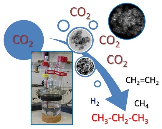
Renewable energy sources such as solar, wind and tidal electricity are also receiving a lot of attention, but they do not produce the constant and tunable currents that fossil fuels provide. Storage of surplus electrical energy produced during peak production periods and its release during peak demand periods is, thus, crucial, especially as peak production and peak demand periods often do not coincide. In this line, the electro-catalytic reduction of CO
2 to hydrocarbons can be an alternative strategy to address the problem of storing temporary and local surpluses of renewable energy [
6,
7]. In a one-pot process, water is split to provide the required hydrogen atoms/ions which are reacted with CO
2 to form hydrocarbons that can be used directly in the existing infrastructure for transportation fuels. Next to storing the renewable energy, some CO
2 is removed from the atmosphere. O
2 is formed simultaneously, which can be used to burn the hydrocarbons to release the energy whenever required. For this process sheet metal electrodes have mainly been investigated [
8,
9,
10].
The direct electrochemical reduction of CO
2 in aqueous solution has been studied mainly on metal electrodes in the form of plates, both at atmospheric pressure and at higher pressures [
9,
11]. So far, copper electrodes have been shown to be quite unique in the activation of CO
2 to hydrocarbons, although the faradaic efficiency is still low as a result of the dissociation of H
2O to H
2. Several studies have been concerned with elucidating the mechanism of electro-reduction of CO
2 to hydrocarbons, which seem to point to a Fischer–Tropsch mechanism of chain propagation [
12,
13].
Cobalt catalysts supported on carbon for CO
2 electro-reduction have not been studied yet in depth, although recently some studies are appearing in the bibliography focusing mainly in cobalt oxidized phases [
14,
15] or coordination complexes [
16]; however, none of these works reported the formation of C3-C4 hydrocarbons.
On the other hand, some types of carbon materials have been used in electro-catalytic CO
2 reduction as support of platinum catalysts, as carbon nanotubes, carbon cloth, or carbon black [
17,
18], obtaining a wide distribution of products of up to nine carbon atoms.
Carbon gels, xerogels, and aerogels are nanostructured materials obtained from the carbonization of organic gels, which are prepared by the sol–gel polycondensation of certain organic monomers, typically resorcinol (R) and formaldehyde (F) [
19,
20]. The textural characteristics of these materials strongly depend on a careful control of the reactant concentrations and the experimental conditions of the different synthesis steps: gelation, curing, drying and carbonization/activation [
21,
22]. For this reason, the surface area, pore volume, and pore size distribution are tunable properties related to the synthesis and processing conditions, enabling the preparation of a wide spectrum of materials with unique properties, e.g., for adsorption and catalytic and electrochemical applications [
23,
24,
25,
26,
27,
28]. Moreover, carbon gels doped with transition metals show a high metal dispersion and a very good distribution of the metals throughout the carbon matrix [
29,
30,
31]. The majority of metal cations will be embedded into the structure of the carbon gel, which minimizes the leaching of the metals in liquid phase applications. In this respect, these materials may have advantages over those catalysts or electro-catalysts prepared by impregnation of the corresponding metallic phase. Nevertheless, a percentage of the metal phase of the doped carbon gels will not be accessible to the reactants, although preparation techniques are available that minimize this aspect [
32].
Recently [
33,
34], Fe-, Cu-, and Ni-doped carbon xerogels, prepared in film form, have been used as working electrodes in the electro-catalytic reduction of CO
2 to hydrocarbons. The use of these doped xerogels as cathodes, instead of the traditional metallic planar-type, reduced the amount of metal required for a similar hydrocarbon production. Although all doped xerogels formed mainly CH
4, the selectivity varied depending on the doping metal.
As far as we know, these types of cobalt-doped carbon materials have never been used as electro-catalysts in the reduction of CO2 to hydrocarbons. Therefore, in the present work we show the application of cobalt-doped carbon gels as promising electro-catalysts in the reduction of CO2 to hydrocarbons. The effect on the activity and selectivity in the reduction of CO2 to hydrocarbons of the different cobalt contents, porosity, and chemical nature of the cobalt-carbon phases of these electro-catalysts, is studied and discussed.
2. Results
Table 1 summarizes the surface areas and pore volumes of the cobalt-doped carbon gels prepared in this work; the numbers in the sample names indicate the approximate percentage of Co content, while A and X refer to aerogel and xerogel, respectively. All of them are microporous and mesoporous materials, with remarkable mesopore volumes and apparent surfaces areas. The highest surface areas and pore volumes are observed in the case of the samples with less doped Co.
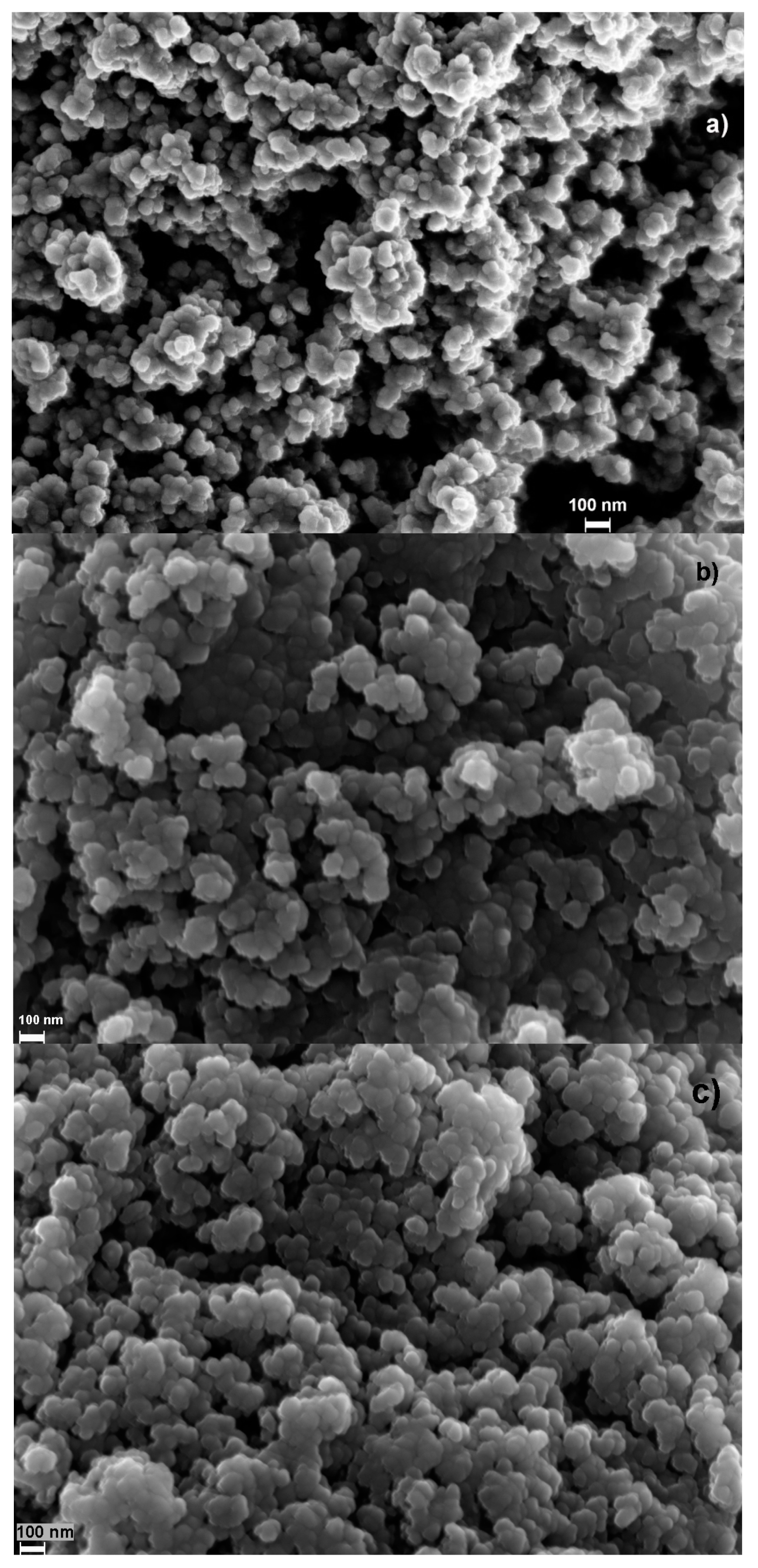
The carbon gel morphology, which was studied by scanning electron microscopy (SEM) (
Figure 1), is typical for R-F carbon gels showing a carbon network formed by nearly spherical particles with different degree of fusion [
31], and where a well-developed macroporous structure can also be observed. Apparently there are no significant morphological differences on the non-porous external surface among the samples.
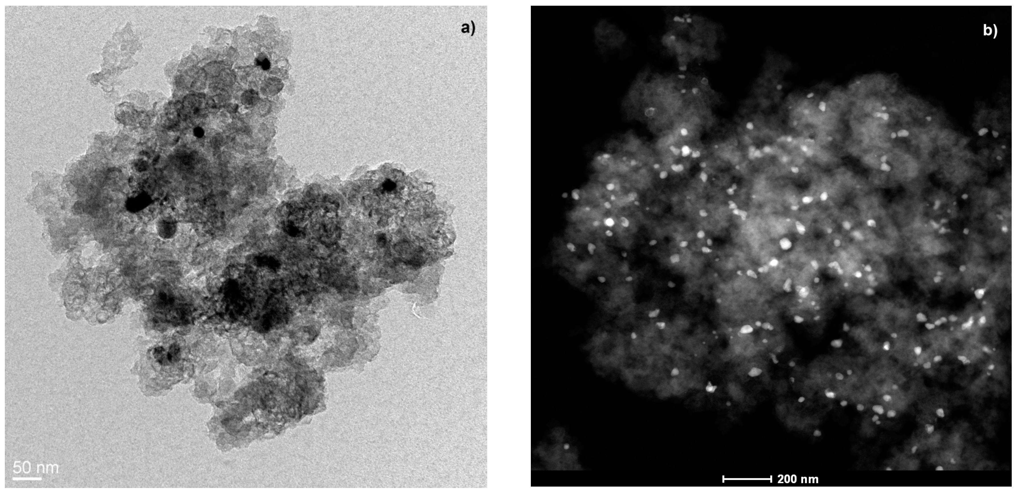
Regarding the Co metal phase characterization, the Co is situated mainly embedded within the carbon matrix, as confirmed by high-resolution transmission electron microscopy (HRTEM) and energy dispersive X-ray analysis (EDAX); these metal particles can be observed in
Figure 2a, in which they are very well dispersed throughout the carbon matrix showing a wide range of sizes within a nanometric scale (
Figure 2b).
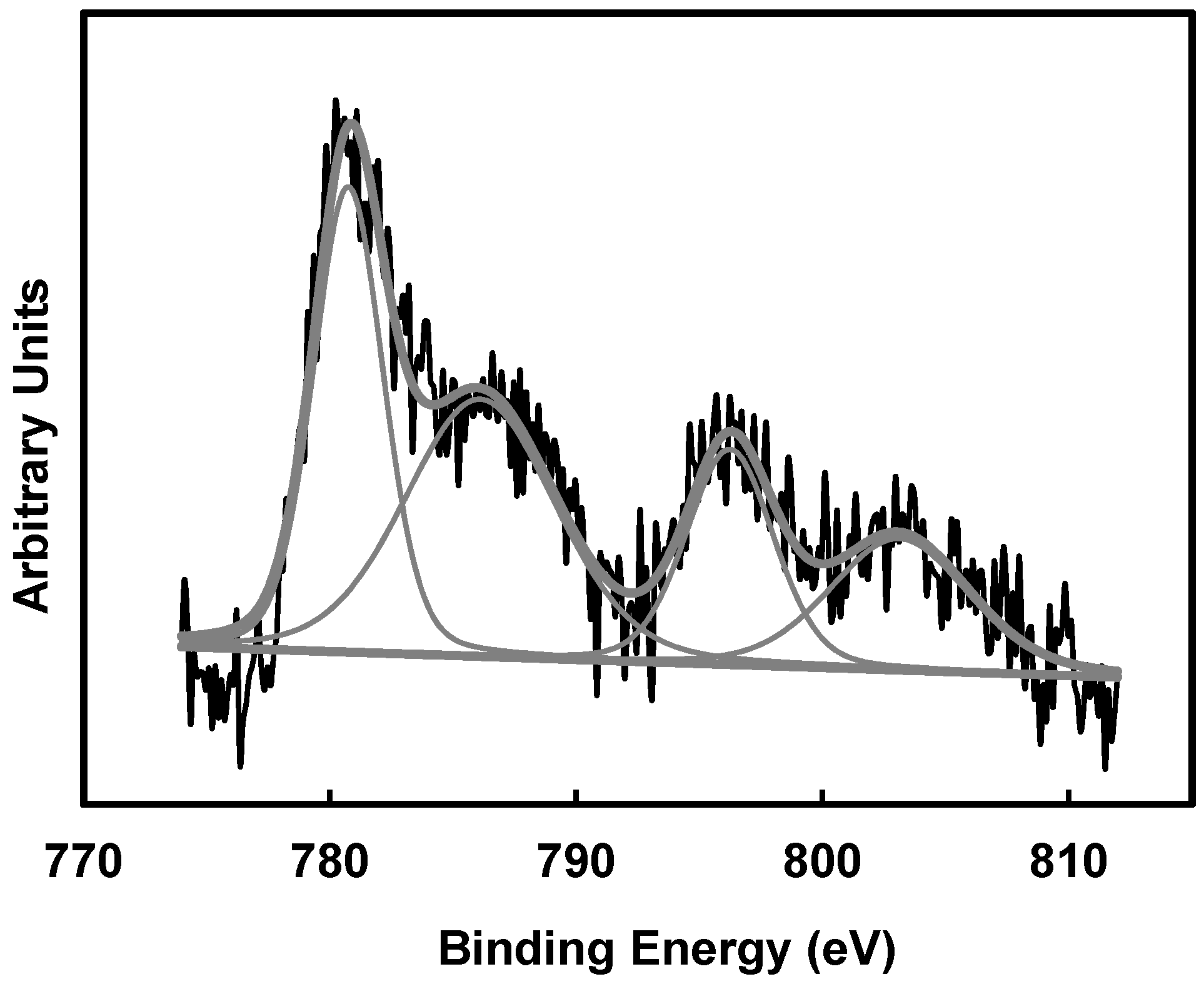
Analysing the X-ray photoelectron spectroscopy (XPS) spectra corresponding to Co 2p, no peaks can be clearly distinguished from the baseline in the spectra corresponding to 1 wt % of Co; therefore, the Co concentration on the external surface of these carbon gels is considered negligible. Only the Co 2p spectra of samples with 6 wt % could be well deconvoluted. A Co 2p
3/2 peak can be observed at 781.1 eV of binding energy (B.E.) in
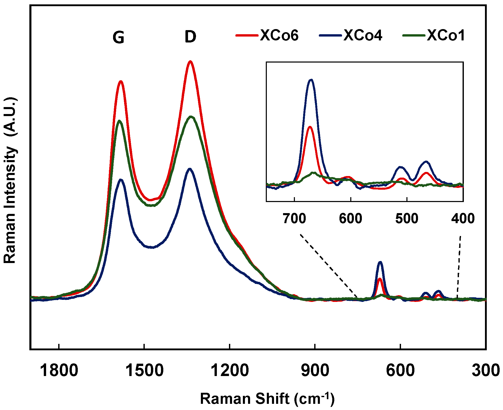
Figure 3, which is assigned to the Co(II) species. The presence of Co(II) species was also corroborated by Raman (
Figure 4). Raman spectra of samples with 4% and 6% of cobalt show four peaks at 672, 607, 510, and 466 cm
−1, which can be well assigned to the presence of Co
3O
4 nanoparticles [
35].
Figure 4 shows two main signals at 1340 and 1580 cm
−1 approx. corresponding to D and G bands, respectively [
36]. It is known that carbon gels are considered as amorphous carbon materials; therefore, the presence of these bands should be analysed into this context: in this type of material, the D band would be associated with alternating ring vibrations in condensed benzene rings [
36], while the G band would be associated to the development of the sp
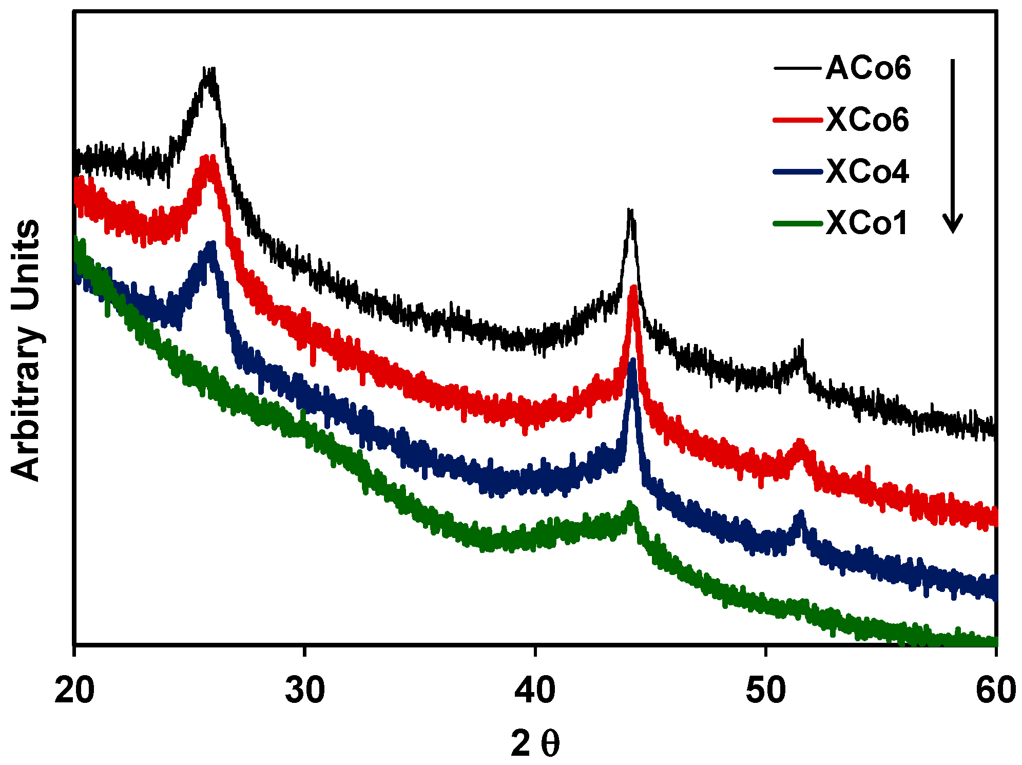
2 carbon structure thought out the material during the carbonization process. Moreover, the presence of Co nanoparticles inside of the organic matrix can also catalyse the development of graphite clusters around the metal particles, during the carbonization process. This could be detected by X-ray diffraction (XRD) as a broad peak at around 26° in the case of samples with 4 and 6 wt % of cobalt content (
Figure 5); this partial graphitization of the Co-doped carbon aerogel structure has been also observed in previous works [
30,
31]. The XRD peaks detected at 44.22° and 51.50° are assigned to metallic cobalt.
Cobalt particle sizes estimated by applying the Scherrer equation (
dXRD), the chemical composition obtained by XPS, and the total cobalt content of the samples are collected in
Table 2. Cobalt particle sizes could not be calculated for samples with the lowest Co content; in the other samples, the main cobalt particle sizes are around 14 nm, with the exception of sample ACo6 in which this value is 21.5 nm. On the other hand, the oxygen surface contents of all the samples range between 3.1 and 3.7 wt %.
All of the samples were used as a cathode in the electro-catalytic reduction of CO2. An un-doped carbon xerogel, a cobalt sheet, and the graphite sheet were also tested as cathodes in the electro-catalytic reduction of CO2; both sheets had dimensions of 50 mm × 8 mm.
The products analysed in the gas phase of the reactor were the following: methane (CH4), ethane (C2H6), ethene (C2H4), propane (C3H8), propene (C3H6), propyne (C3H4), and n-butane (C4H10). The molar production will be described in terms of C1, C2, C3, and C4 hydrocarbons, with 1 to 4 being the number of carbon atoms in the molecules in order to simplify the discussion about the reaction selectivity. Nevertheless, methane was the major product in all cases, and minor amounts of other detected products (probably C4 isomers, or C5, hydrocarbons) have not been quantified.
It should be remarked that an “induction period” [
33] was not observed and the reaction products were detected since the beginning of the monitoring; this is ascribed to the mesoporosity of the samples which gives good accessibility to the electrolyte inside the porous network, together with the fact that electrodes were submerged in the electrolyte overnight and before the start of the reaction. Nevertheless, the adsorption of a part of the products in the porous structure of the carbon gel cannot be ruled out.
On the other hand, before the discussion, it is necessary to clarify that when an electrolyte free of dissolved CO2 was used (that is, carrying out the reaction under Ar-saturated solution) no hydrocarbons were detected in any case. Using both under normal experimental reaction conditions, using a graphite sheet or an un-doped carbon xerogel sheet as cathodes, no hydrocarbons were detected.
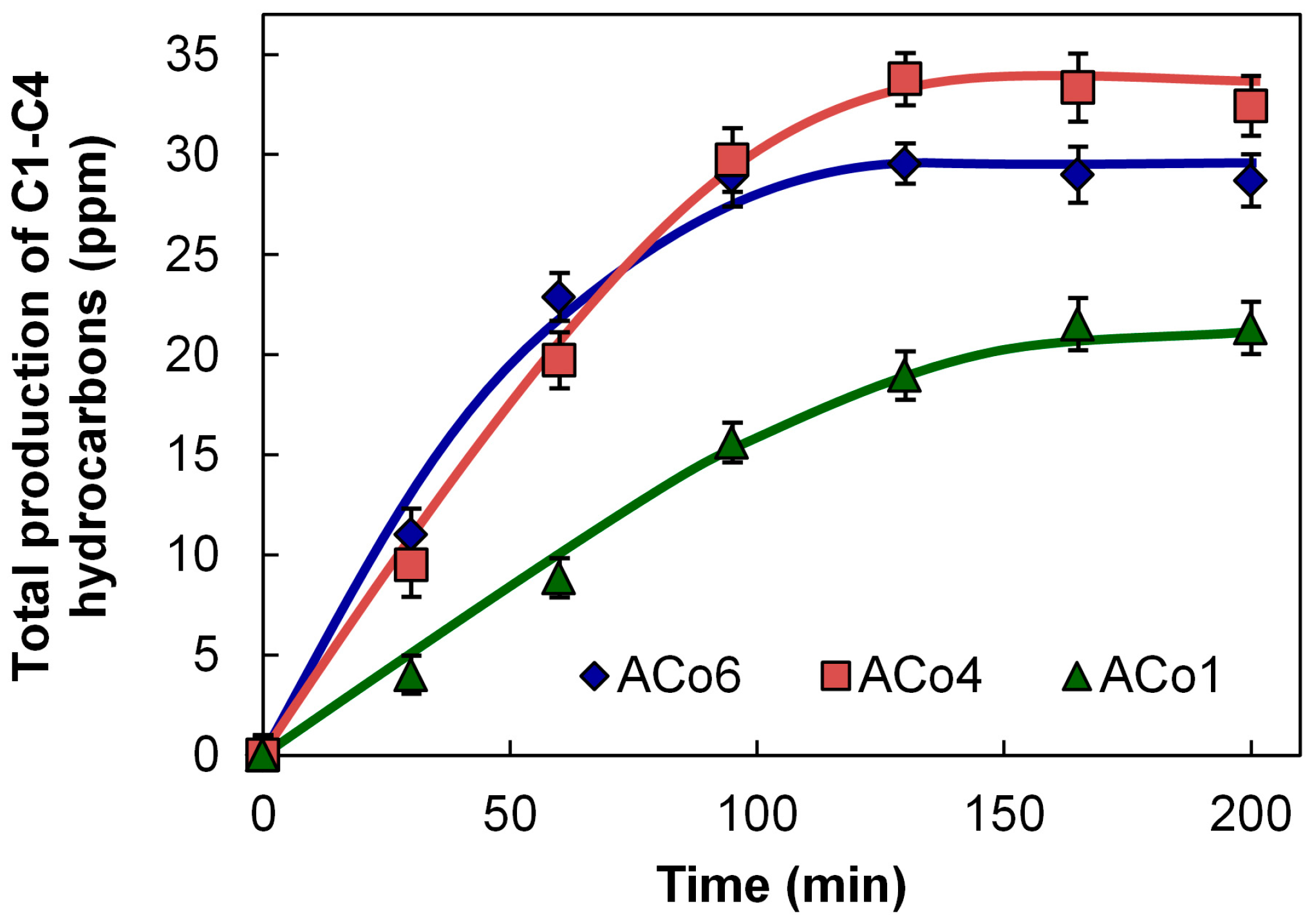
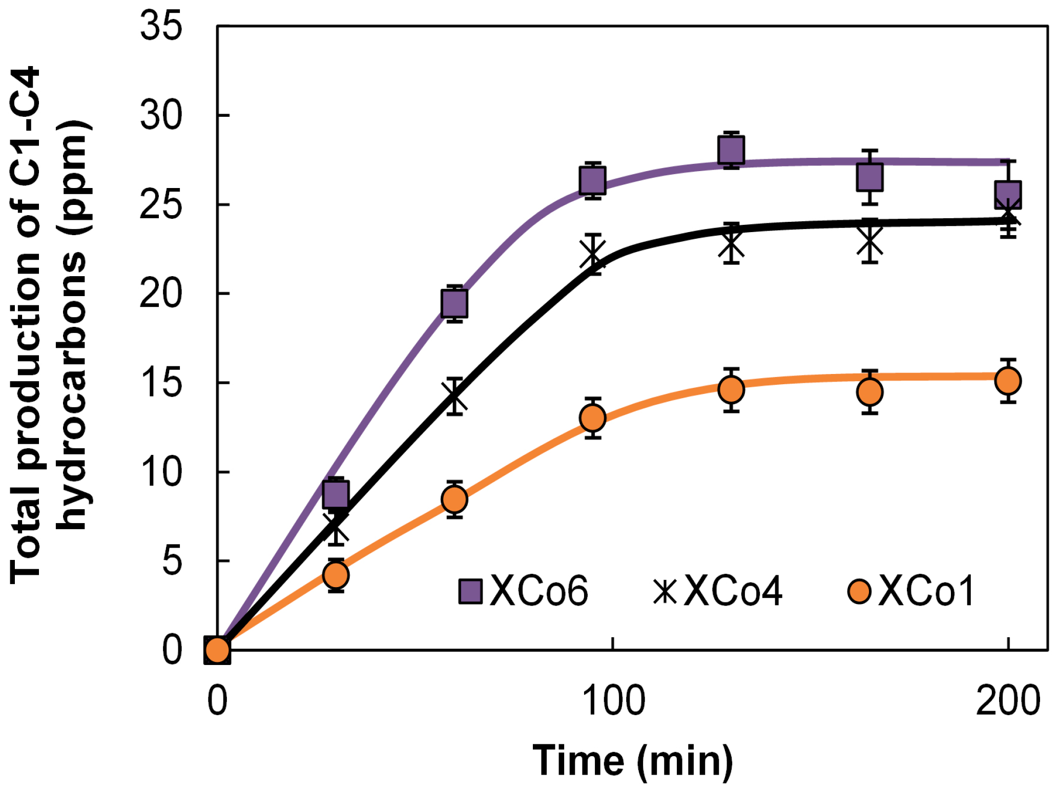
Data of the total molar productions in the reactor are collected in
Figure 6 and
Figure 7. These figures show the general tendency that the higher the Co loading, the higher the hydrocarbon formation in both aerogels and xerogels series. This tendency is also clearly observed with the values of the apparent faradaic efficiencies (F.E.) collected in
Table 3, being the average of them of the same order that the F.E. calculated for the Co sheet, in spite of the much larger amount of Co used in this last cathode.
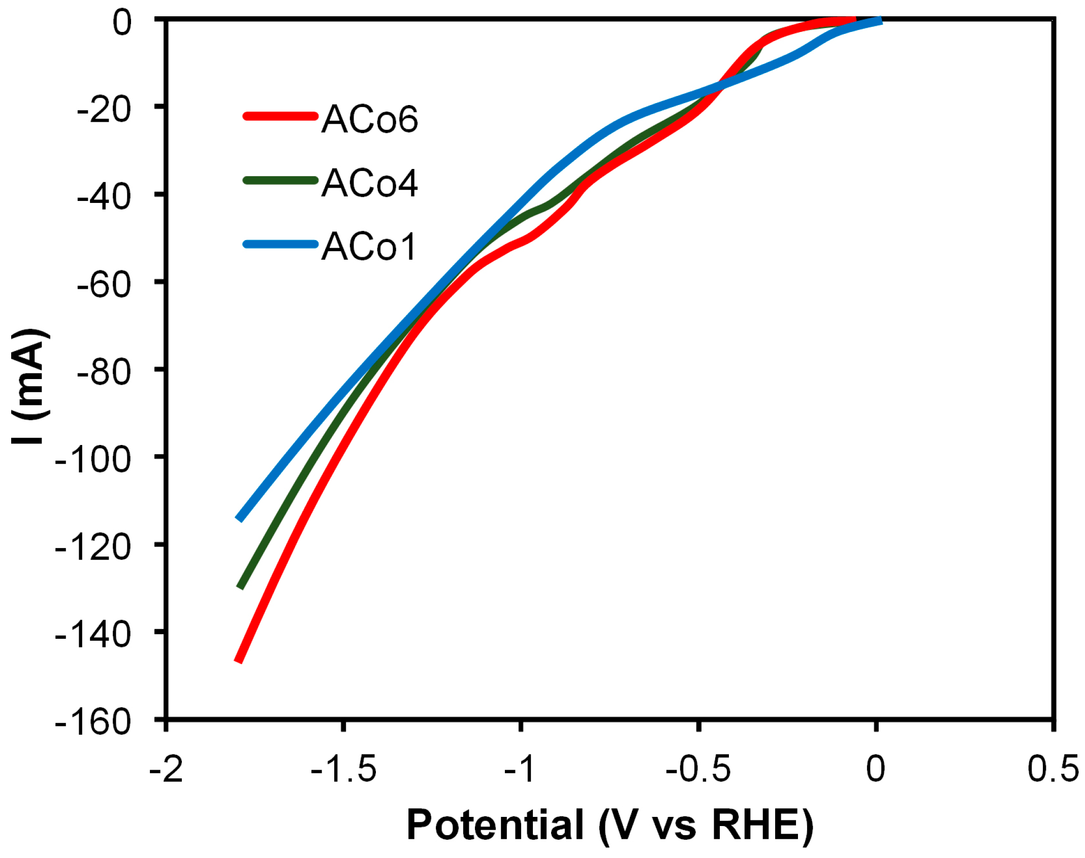
Figure 8 compares the linear sweep voltammetry (LSV) curves of CO
2 reduction obtained with the three aerogels. Current values at –1.44 V clearly increased with the increase of Co loading, indicating, consecutively, additional CO
2 reduction reaction activity. This tendency is in agreement with the apparent faradaic efficiencies and the total amount of hydrocarbons detected using these electro-catalysts.
Cobalt leaching in the liquid solutions was studied in all cases by ICP-OES. The detected cobalt concentrations in the liquids were always lower than 100 ppb, which means that Co leaching was not higher than 0.5 wt % of the metal phase in the worst case.
The electrodes were weighed before and after reaction and no weight changes were detected. Finally, the catalysts with the highest cobalt loading were also analysed after reaction by XPS, detecting both Co2+ and Co0 species in a ratio of 4:6, respectively.
3. Discussion
Taking into account all characterization data collected in
Section 2, we can conclude that the cobalt-doped gels are materials with a very well-developed porosity, all of them with a remarkable mesoporosity, and with a Co phase well-dispersed and distributed mainly into the carbon matrix. Therefore, Co particles show a broad range of nanometric sizes, being mainly embedded in the carbon matrix with a zero oxidation state, while a very low percentage of the cobalt would be situated in the external non-porous surface area, being these particles partially oxidized. The carbon matrix macro-structure is very similar among the samples, however, in samples with 4 and 6 wt % of Co, a partial graphitization process has also been detected by XRD.
From the catalytic point of view, a correct comparison of the electro-catalytic behaviour of these materials is, however, not straightforward because the tested cathodes do not have exactly the same textural characteristics, although there is reasonable similarity among them, but also the main Co particle size of ACo1 and XCo1 could not be calculated. Nevertheless, it is demonstrated that the Co-doped carbon gel works as an electro-catalyst in this reaction, the hydrocarbons formation and F.E. increases directly proportional to the total cobalt content, and no previous report has been found in the literature on this type of electro-catalysts.
Analysing more deeply the electro-catalytic results from
Figure 6 and
Figure 7, we can see that the hydrocarbon formation seems to stop around 100 min of reaction time. In this line, it should be noticed that there are three other different processes that are simultaneously taking place, which can explain this observation: (i) the formation of high amounts H
2 and O
2; (ii) a probable adsorption of hydrocarbons inside of the micropores; and (iii) a partial leaching of the particles situated in the porous and non-porous external surface. The high formation of H
2 and O
2 can provoke a dilution effect of the hydrocarbon formation in the gas phases of the reactor.
As it was mentioned in
Section 2, the higher the Co loading, the higher the hydrocarbon production, however this clear general tendency should be commented taking into account not only Co loading, but also the main cobalt particle sizes and the porous texture. In this way, the relative and apparent low catalytic activity of ACo6 in comparison with ACo4 (
Figure 6) can be due to the fact that ACo6 has a higher main Co particle size than ACo4 (
Table 2). On the other hand, the highest mesoporosity and, mainly, microporosity of samples ACo1 and XCo1 can positively contribute to the above-mentioned tendency because in these two samples the amount of adsorbed hydrocarbons could be higher. Finally, it is very important to remark that processes (i) and (ii) have not been included in the faradaic efficiency calculations. In any case, the more remarkable aspect of this data is the fact that in spite of the much larger amount of Co used with the cobalt sheet (a sheet of 50 mm × 8 mm × 0.25 mm thick versus 80 mg of each carbon gel), all of the apparent F.E. are comparable with the Co sheet, with some of them showing even higher values (
Table 3).
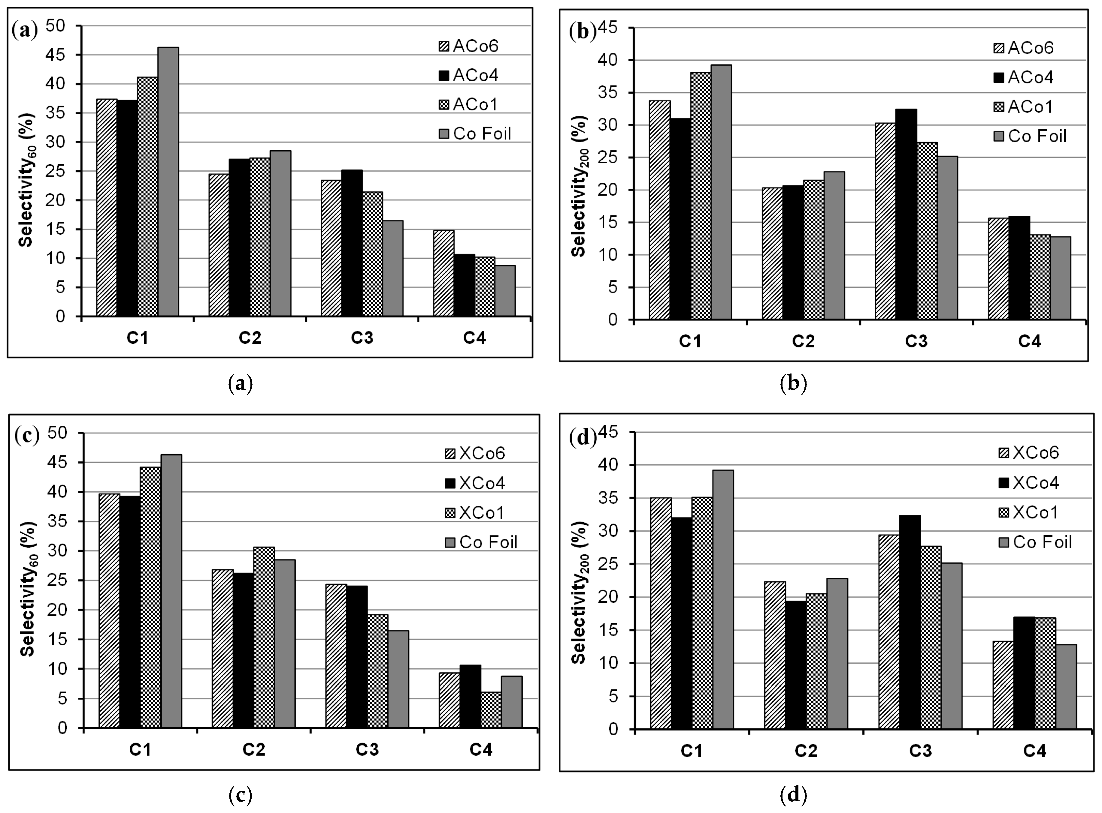
Regarding to the selectivity of these materials to the hydrocarbons formation,
Figure 9 contains these data at two reaction times, 60 and 200 min. It can be observed in this Figure that the selectivity not only depends on the reaction time, but also of the type of cathode. Co-doped gels are clearly more selective to C3-C4 hydrocarbons, mainly C3, than the Co sheet in all of the cases and independently of the studied reaction time. The selectivity sequence observed at 60 min of reaction time is C1 > C2 > C3 > C4 (
Figure 9a,c); being the carbon gels already more selective to C3 than the Co sheet at this reaction time. At a higher reaction time (200 min) using carbon gels, especially with ACo4 and XCo4, the above mentioned sequence changes, being the C3 hydrocarbon production close to or even higher than the C1 one (
Figure 9b,d). This change on the selectivity does not seem to be due to an effect of the carbon matrix mesoporosity because the corresponding A-X couples show similar selectivity; however, it might be due to an effect of the metal-carbon interaction. Therefore, the presented results show that this type of cobalt-carbon composites are very interesting as electro-catalysts in the CO
2 reduction reaction, not only because they show better faradaic efficiencies than traditional Co sheet but because this combination of phases improves the selectivity to C3-C4 hydrocarbons formation. In this line and for a future work, the effect of the metal particle size is an important aspect that should be studied in order to better understand the electro-catalytic selectivity of cobalt in this reaction, for this proposal will be necessary the preparation of cobalt-carbon composites with different mean cobalt particle sizes.
4. Materials and Methods
Cobalt-doped carbon gels were prepared by dissolving resorcinol (R) and formaldehyde (F) in water (W) and using the corresponding metal acetate as a catalyst precursor (C). The used (R/F) and molar ratio (R/W) were 1:2 and 1:17, respectively. Different amounts of C were used in order to obtain three different Co loadings (1, 4, and 6 wt %, approx.) among the final carbon aerogels and xerogels. The mixture was stirred to obtain homogeneous solutions that were cast into glass molds and cured for one day at 40 °C, and for five days at 80 °C, obtaining the corresponding organic gels. Then, the organic gels were immersed in acetone to exchange the solvent media. Two different drying processes, supercritical CO2 or thermal oven, were carried out in order to obtain the aerogel (A) or xerogel (X) series, respectively. Finally, the organic gels were carbonized in a N2 flow at 900 °C during 5 h, and using a heating rate of 1 °C/min. The names of the obtained carbon gels were the following: ACo1, ACo4, ACo6, XCo1, XCo4, and XCo6, indicating the numbers the approximate percentage of Co content. The cobalt contents of the samples were determined by burning off a portion of carbon gel at 800 °C in air and weighing the residue.
The characterization of the samples was carried out using gas adsorption, scanning electron microscopy (SEM), high-resolution transmission electron microscopy (HRTEM), Raman spectroscopy, X-ray diffraction (XRD), X-ray photoelectron spectroscopy (XPS), and linear sweep voltammetry (LSV).
The porous texture was analyzed by N2 adsorption at −196 °C. Prior to measuring the N2 adsorption isotherms, the samples were outgassed overnight at 110 °C under high vacuum (10−6 mbar). The BET equation was applied to the N2 adsorption data from which the apparent surface area, SBET, was obtained. The Dubinin-Radushkevich (DR) equation was applied to the N2 adsorption data in order to obtain the corresponding micropore volume (W0) and micropore mean width (L0). Total pore volumes (V0.95) are calculated from N2 adsorption isotherms at −196°C and at 0.995 relative pressure, and the corresponding mesopore volumes (VMESO) were calculated by difference between V0.95 and W0. Finally, SDFT is the cumulative surface area obtained from the pore size distribution determined applying the quenched solid state functional theory (QSDFT) method for slit-shaped pores.
SEM was performed using a Zeiss SUPRA40VP scanning electron microscope (Carl Zeiss AG, Oberkochen, Germany), equipped with secondary electron detector, back-scatter electron detector, and using an X-Max 50 mm energy dispersive X-ray microanalysis system. All of the samples were crushed before realizing this analysis.
HRTEM was carried out using a FEI Titan G2 60-300 microscope (FEI, Eindhoven, The Netherlands) with a high-brightness electron gun (X-FEG) operated at 300 kV and equipped with a Cs image corrector (CEOS) and, for analytical electron microscopy (AEM), a SUPER-X silicon-drift window-less EDX detector. The AEM spectra were collected in STEM (scanning transmission electron microscopy) mode using a HAADF (high angle annular dark field) detector. Digital X-ray maps were also collected on selected areas of the samples.
Raman spectra were obtained using a Micro-Raman JASCO NRS-5100 dispersive spectrometer with a 532 nm laser line (JASCO Inc., Easton, MD, USA).
XRD patterns were recorded with BRUKER D8 ADVANCE diffractometer using Cu Kα radiation (BRUKER, Rivas-Vaciamadrid, Spain). JCPDS files were searched to assign the different diffraction lines observed. Diffraction patterns were recorded between 5° and 70° (2θ) with a step of 0.02° and a time per step of 96 s. The average crystal size was determined using the Scherrer equation.
XPS measurements of the fresh samples were performed using a Physical Electronics ESCA 5701 (PHI, Chanhassen, MN, USA) equipped with a Mg Kα X-ray source (hν = 1253.6 eV) operating at 12 kV and 10 mA, and a hemispherical electron analyzer. For these measurements, the binding energy (BE) values were referred to the C 1s peak at 284.7 eV. A base pressure of 10−9 mbar was maintained during data acquisition. Survey and multi-region spectra were recorded at C 1s, O 1s, and Co 2p photoelectron peaks. Each spectral region of interest was scanned several times to obtain good signal-to-noise ratios. The spectra obtained after background signal correction were fitted to Lorentzian and Gaussian curves in order to obtain the number of components, the position of each peak and the peak areas. For XPS analysis of the samples used in reaction, the procedure was the following: once the reaction was finished, the sample was dried under He flow, impregnated with n-octane, and then transferred to the pretreatment chamber of the XPS instrument. Prior to the XPS analysis the samples were evacuated at high vacuum and room temperature, and then introduced into the analysis chamber. A base pressure of 10−9 mbar was maintained during data acquisition.
Electro-catalytic conversion of CO
2 was carried out in a three-electrode cell of 300 cm
3 of capacity at ambient temperature and pressure. A Biologic VMP multichannel potentiostat was used to induce an electro-catalytic reduction by applying adequate potential differences over the electrodes. A platinum electrode was employed as a counter electrode, and Ag/AgCl as the reference electrode. A CO
2-saturated 0.1 M potassium bicarbonate aqueous solution (150 cm
3) was used as the electrolyte. The setup was used in potentiostatic mode at –1.65 V, because at this voltage maximum hydrocarbon formation has been typically reported in CO
2 electro-catalytic reductions, using Ag/AgCl as the reference electrode [
13] (−1.44 V vs. reversible hydrogen electrode, RHE). Prior to the electro-catalytic CO
2 reduction, the solution was saturated with CO
2 by bubbling through for 3 h. After saturation, the pH of the solution was 6.7. The CO
2 feed and exit lines were closed off, and the reactor was operated in batch mode. The amount of carbon gel used as electro-catalyst in the working electrode was 80 mg which was homogeneously pasted on the both face of a graphite sheet with dimensions of 50 mm × 8 mm. In the preparation of the working electrode the carbon gel was mixed with the corresponding amount of PTFE in a weight ratio of (80:7) using a PTFE (60%) water solution. Working electrodes were kept in 0.1 M potassium bicarbonate aqueous solution overnight before being used in the electro-reactor.
All cobalt-doped carbon gels were characterized by LSV. The cathodic sweep analysis was conducted from the equilibrium electrode potential to negative electric potential (−1.79 V vs. RHE), with a scan rate of 5 mV/s, using the same experimental conditions and reactor set-up that those for the electro-catalytic CO2 conversion.
Gas phase hydrocarbons produced by the electrochemical reduction of CO2 at the fixed potential were analyzed using a gas chromatograph (GC) where gases were directly injected into the column for GC analysis using a gas recirculating pump for low flows. The GC was equipped with a FID and TCD detectors (carrier gas: He, column: Chrompack Poraplot Q, 50 m × 0.53 mm). Production of CO was below the detection limit of the TCD applied in the GC analysis after separation.
The distribution of gaseous products is expressed in terms of the carbon selectivity
SCi, the amount of carbon (from CO
2) in a specific product, relative to the total amount of carbon in the detected hydrocarbons:
where
nC
i represents the mol of product C
i, and
i the number of carbon atoms in that product.
The water phase was also analyzed by headspace gas chromatography-mass spectrometry in order to determine the formation and concentration of organic products, using other GC equipped with a HP-INNOWax 30 m × 0.25 mm × 0.25 µm column (Agilent Technologies, Santa Clara, CA, USA), which was coupled to a MS-Triple quadrupole. The presence of alcohols or carboxylic acids of one to four carbon atoms were not detected.
For comparative purposes a commercial Alfa Aesar® (Karlsruhe, Germany) cobalt sheet (99.95% metal basis, 0.25 mm thick), a sheet of graphite from Alfa Aesar® (99.8%, 0.25 mm thick) and an un-doped carbon aerogel were also tested as cathodes.
The amount of cobalt leached into the solution during reaction was determined by inductively coupled plasma optical emission spectrometry (ICP-OES) using an ICP-OES PerkinElmer OPTIMA 8300 spectrometer (PerkinElmer, Madrid, Spain).


 ,
, 


