Article

The Performance of Electron-Mediator Modified Activated Carbon as Anode for Direct Glucose Alkaline Fuel Cell

1
Tianjin Key Laboratory of Indoor Air Environmental Quality Control, School of Environmental Science and Engineering, Tianjin University, Tianjin 300072, China
2
College of Food Science and Engineering, Tianjin Agricultural University, Tianjin 300384, China
*
Authors to whom correspondence should be addressed.
Catalysts 2016, 6(7), 95; https://doi.org/10.3390/catal6070095
Submission received: 24 May 2016 / Revised: 19 June 2016 / Accepted: 23 June 2016 / Published: 28 June 2016

Abstract

:
Six different electron mediators were immobilized on the activated carbon (AC) anode and their effects on performance of a direct glucose alkaline fuel cell were explored. 2-hydroxy-1, 4-naphthoquinone (NQ), methyl viologen (MV), neutral red (NR), methylene blue (MB), 1, 5-dichloroanthraquinone (DA) and anthraquinone (AQ) were doped in activated carbon (AC), respectively, and pressed on nickel foam to fabricate the anodes. NQ shows comparable performance with MV, but with much lower cost and environmental impact. With NQ-AC anode, the fuel cell attained a peak power density of 16.10 Wm−2, peak current density of 48.09 Am−2, and open circuit voltage of 0.76 V under the condition of 1 M glucose, 3 M KOH, and ambient temperature. Polarization curve, EIS and Tafel measurements were also conducted to explore the mechanism of performance enhancement. The high performance is likely due to the enhanced charge transfer and more reactive sites provided on the anode.

Graphical Abstract

1. Introduction

In recent years, with the rapid development of global industrialization, environmental problems caused by fossil fuel combustion are becoming more and more serious [1,2,3,4,5]. As possible alternatives of fossil fuel, biomass resources—one of the renewable energy sources—has attracted much attention [6,7,8,9,10].
As the most important monose in nature, glucose can be directly obtained from a great quantity of waste biomass. It is inexpensive, nontoxic, easy to use, and environmentally friendly [11,12]. As result of these advantages, glucose is viewed as one of the most appropriate fuels for fuel cells. Over the past decades, research on glucose fuel cells have developed rapidly. These fuel cells mainly include enzymatic glucose fuel cells (EGFCs), microbial glucose fuel cells (MGFCs), and direct glucose alkaline fuel cells (DGAFCs). EGFCs employ a variety of specific enzymes to oxidize glucose. They are typically limited by their extremely low performance, poor stability, as well as the lack of sustainability [12,13,14]. In this respect, MGFCs have the better performance than EGFCs. They can relatively keep long-term durability. However, the most crucial issue for MGFCs is the low electronic conversion rate, and using noble metals significantly increases the cost of the device [15,16,17].
DGAFCs can tackle these problems by direct conversion of chemical energy into electrical power without enzymes and microorganisms. Precious metals, such as platinum and gold, and nanomaterials are normally employed to catalyze the oxidation of substrate [18,19,20,21]. However, the high cost of these catalysts can seriously hinder the practical application of DGAFCs. Furthermore, it has been found that the catalytic ability of these noble metal catalysts are easily impaired by intermediates of oxidation reaction process [22]. To develop a low cost DGAFC for portable devices, Schechner et al. used electrospinning and an electroless plating method to prepare polycaprolactone fibrous anode membranes coated with silver. With a 0.9 μm mean plated fiber diameter membrane, the cell achieved an open circuit voltage of 0.385 V and a peak power density of 196 μWcm−2 [11]. Their experimental results indicate that the electrical performance of the fuel cell is proportional to the surface area of the fibrous anodes. Zhao et al. reported a DGAFC based on Ni foams has no catalyst poisoning effect which can be easily found in Pt-based glucose fuel cells. The fuel cell produced a maximum power density of about 0.014 mWcm−2 under the condition of 0.5 M glucose, 0.5 M KOH, cathode gas: humidified O2 at 10 mL·min−1 and room temperature [23]. A simple DGAFC that used PtRu/C as anode and activated charcoal as cathode was reported by Basu et al. [24]. The maximum peak power density of 1.38 mWcm−2 was achieved under the condition of 0.2 M glucose, 1 M KOH and 30 °C. Chen et al. reported a DGAFC with an anion-exchange membrane (AEM) and Ag/Ni foam electrodes, and a maximum power density of 2.03 mWcm−2 at 80 °C was produced [25].
Electron mediators are normally used to accelerate the electron transfer and improve the fuel cell performance. In a prior work, a two-chamber glucose alkaline fuel cell was investigated, which used methyl viologen (MV) and nickel foam as an electrocatalyst to facilitate glucose oxidation reaction at the anode. The fuel cell obtained the maximum power density of 5.20 W·m−2 under the condition of 3 M KOH, 1 M glucose, and 25 °C. However, MV is high-cost and has adverse impact to the environment. In order to find low-cost and environmentally-friendly MV alternatives, herein, activated carbon (AC) anode modified by six different electron mediators was prepared and examined. To our knowledge, this is the first report of the direct combination of electron mediators and AC composite as anode catalysts for glucose oxidation in DGAFC. Furthermore, comprehensive characterizations including linear sweep voltammetry (LSV), electrochemical impedance spectroscopy (EIS), and Tafel measurements were also conducted to explore the mechanism.

2. Results and Discussions

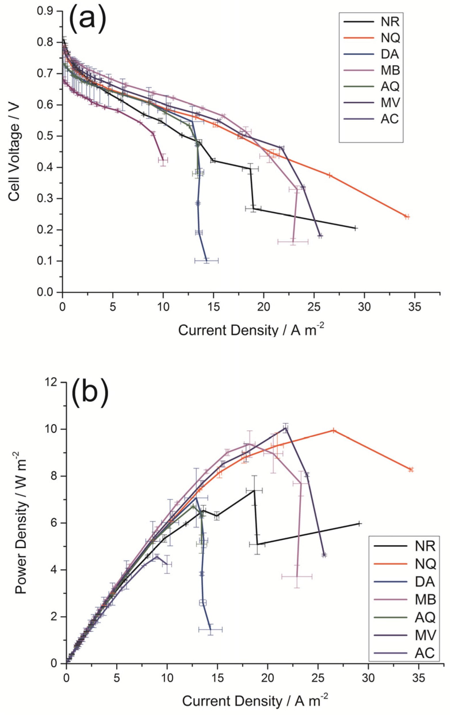
2.1. Effects of Doping with Different Electron Mediators on DGAFC Performance

The effect of doping with different electron mediators on the fuel cell performance is presented in Figure 1. Table 1 lists molar mass, molecular structure, molecular formula, soluble in ethanol solution, cell voltage, current density, power density, and market prices of six different electron mediators. The mass ratio of AC and each electron mediator solution is 1:1 on the anode. The cell equipped with MV doped AC (MV-AC) anode exhibits the best performance, with open cell voltage of 0.78 V, peak power density of 10.05 Wm−2, and peak current density of 25.61 Am−2.The cell equipped with NQ doped AC (NQ-AC) anode has comparable performance with the cell equipped with MV-AC anode, with open cell voltage of 0.79 V, peak power density of 9.95 Wm−2, and peak current density of 34.23 Am−2.
Table 1 indicates solubility of the electron mediator can affect the performance of the fuel cells. The solubility is related to the molecular structure, including the species and quantity of functional groups. Electron mediators are more likely to be evenly distributed on the surface of AC, if they have the better solubility. Good solubility makes contribution to increasing specific surface area for the electron transfer, leading to the enlargement of the contact area for electrons and better conduction for electrons to current collector. Table 1 also shows molecular size of the electron mediator has influence on fuel cell performance. Small electron mediators have better performance. Both the solubility and the molecular size are related to their chemical diffusion coefficient. Diffusion coefficient is used to represent the active degree of the movement and is crucial for determining the reaction rate [26]. Compared with other electron mediators, MV and NQ have smaller molecular size, and better solubility, which lead to a higher chemical diffusion coefficient. Therefore, the high performance of MV and NQ should be contributed to their high chemical diffusion coefficients. Furthermore, as a surface related process, the electrochemical reaction is sensitive to the variation of phase interface [23]. When electron mediators are immobilized on the surface of AC, a new two-phase interface between liquid and solid phase forms. Different electron mediators form different phase interfaces. Among them, MV and NQ, which have better properties, can provide more reaction sites at the anode.
Table 1 indicates NQ and MV have comparable electrochemical performance. MV has been widely reported as an electron mediator for glucose fuel cell [27]. However, MV is highly toxic. NQ is an ancient natural dye and can be extracted from the plants. It is low-cost, low-toxicity, and has no or neglectable adverse impact on the environment. Thus, NQ was chosen as a potential alternative electron mediator for MV and the electrochemical behavior of the NQ doped anode was further examined

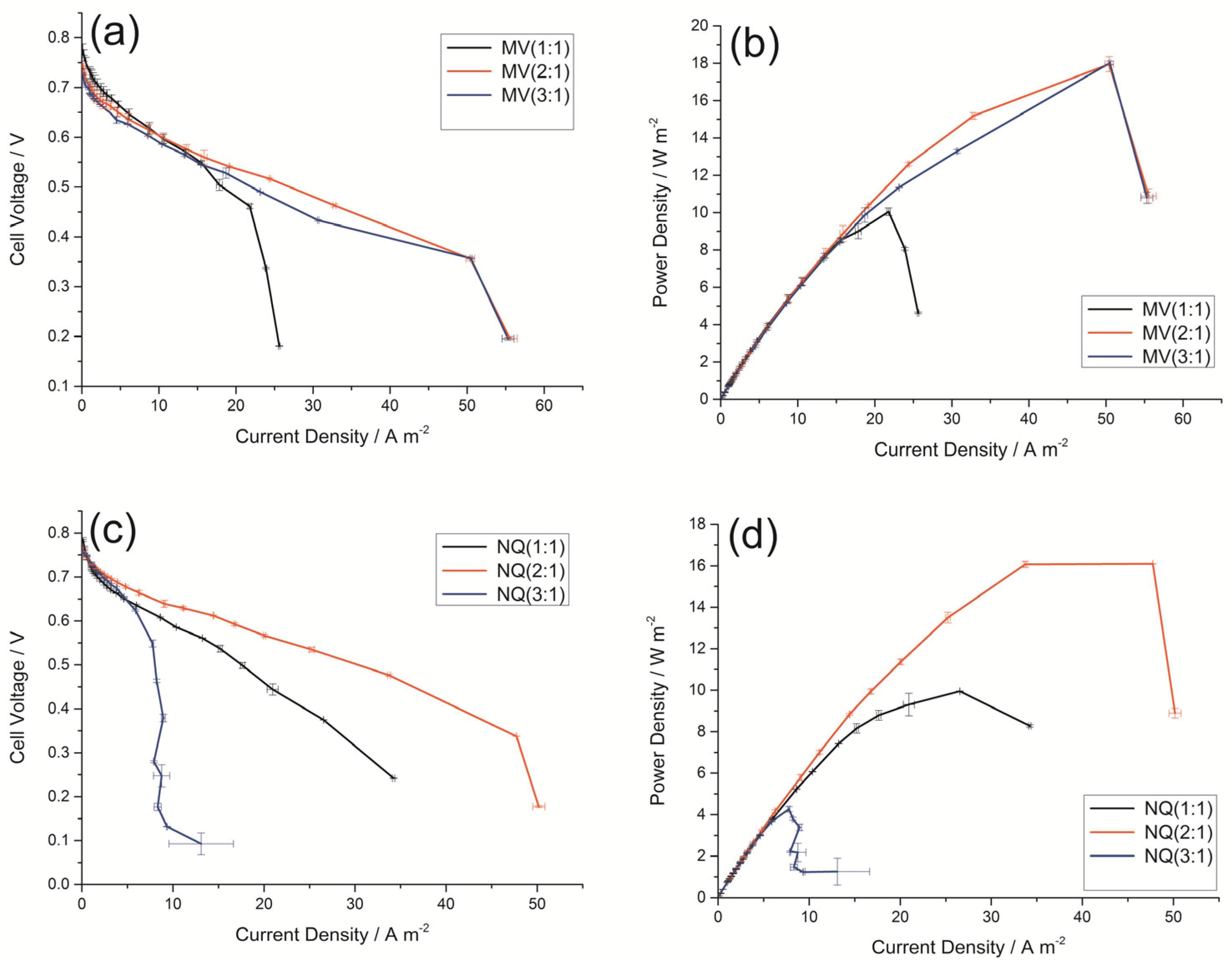
2.2. Effect of Different Mass Ratio of Electron Mediator/AC on DGAFC Performance

Figure 2a–d shows the cell performance with different MV-AC and NQ-AC anodes, respectively. Peak power densities of 10.05 Wm−2, 17.95 Wm−2, and 18.01 Wm−2 are obtained for DGAFCs equipped with 1:1, 2:1, 3:1 (mass ratio of 30 mM MV solution/AC) anodes, respectively. Peak current densities obtained are 25.61 Am−2, 55.53 Am−2, and 55.30 Am−2 for DGAFCs equipped with 1:1, 2:1, 3:1 MV-AC anodes, respectively. Peak power densities of 9.95 Wm−2, 16.10 Wm−2, and 4.26 Wm−2 are obtained for DGAFCs equipped with 1:1, 2:1, 3:1 (mass ratio of 30 mM NQ solution/AC) anodes, respectively. Peak current densities obtained are 34.23 Am−2, 50.18 Am−2, and 13.10 Am−2 for DGAFCs equipped with 1:1, 2:1, 3:1 NQ-AC anodes, respectively. DGAFCs shows higher performance with anodes doped with higher mass ratio of electron mediators. The explanation is that high concentration of electron mediator can increase the contact sites between the liquid-solid phases, and decrease the internal cell resistance. It is beneficial to capture and deliver more electrons, and accelerate the reaction rate [12]. However, the area of the anode is limited with confined contact sites, and when the concentration of electron mediator surpass the upper limit, electron mediators cannot get charge, thus slowing down the process of electron transfer. In addition, the catalytic effects of electron mediators are restricted by many other factors, including the concentration of glucose and KOH, temperature, etc. [27]. Therefore, there will exist an optimum concentration of electron mediators. This is why the NQ-AC anode has the best performance when NQ vs. AC is 2:1; while the MV-AC anode has the best performance when MV vs. AC is 3:1.

2.3. Electrochemical Characterization

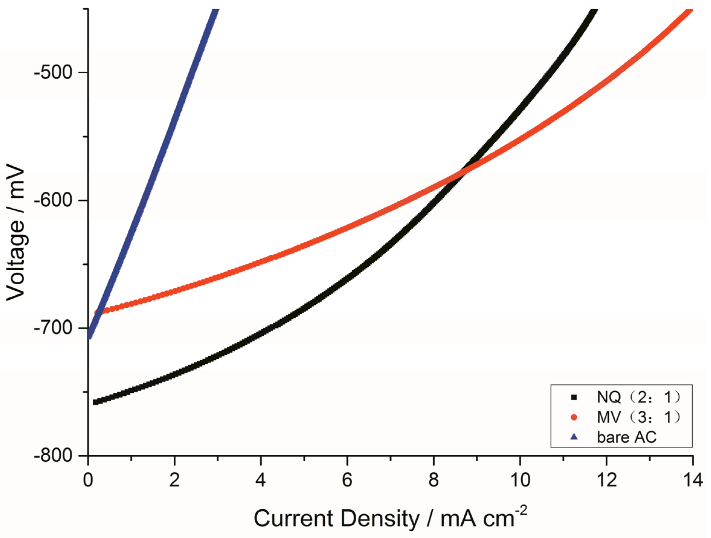
2.3.1. LSV Polarization Curves of the Anodes

The LSV polarization curves of the AC anodes doped with NQ (2:1) and MV (3:1) at different current densities are shown in Figure 3. The slopes of the anode voltage–current densities are different with the increasing order of MV (3:1) < NQ (2:1) < bare AC (blank control group). With electrode polarization curve becoming steeper, the potential deviation degree becomes greater and the polarization is more serious. It means that the resistance on electrode tends to be very large. On the contrary, if the curve is smooth, it illustrates that the degree of polarization is small and no obstacles exist in the process of reaction. Therefore, the polarization degree of bare AC anode is much greater than NQ and MV doped AC anodes, and the electrochemical power performance of the bare AC anode is the worst among them. This data indicates that the NQ-AC (2:1) anodes and MV-AC (3:1) anodes have better electrochemical properties, which is consistent with the DGAFC performance results.

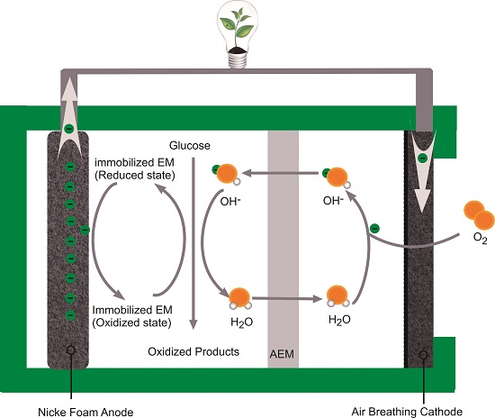
2.3.2. EIS of the Anodes

EIS was used in this work to investigate the electrochemical performance of different anodes. Figure 4 shows the Nyquist plot for different anodes. In the high-frequency region, the x-intercept of the Nyquist plot presents an ohmic resistance (Ro). The ohmic resistances of different anodes are nearly the same, which may result from the same electrolyte solution applied in the study. The semicircle diameter in Nyquist plot, which is an indicator of charge transfer resistance (Rct) [28], is smaller for MV (3:1) and NQ (2:1) than bare AC, further confirming that MV and NQ, if an optimal amount is added, does improve the catalytic activity of AC anode. Rct of the AC, NQ (2:1), and MV (3:1) anodes have an apparent trend, with the order of: bare AC > NQ (2:1) > MV (3:1). The Rct of the bare AC anode was 8.972 Ω, which was 19.84 times as much as the NQ (2:1) anode (0.4522 Ω), and 28.93 times as much as the MV (3:1) anode (0.3101 Ω) (Table 2). MV and NQ fixed on the surface of AC can directly transfer electrons between glucose and current collector, leading to the reduction of charge transfer resistance. Among all resistances, the charge transfer resistance is dominant. That is the reason why the performance of NQ and MV anodes are much better than activated carbon anodes. These results are consistent with those of the polarization curve.

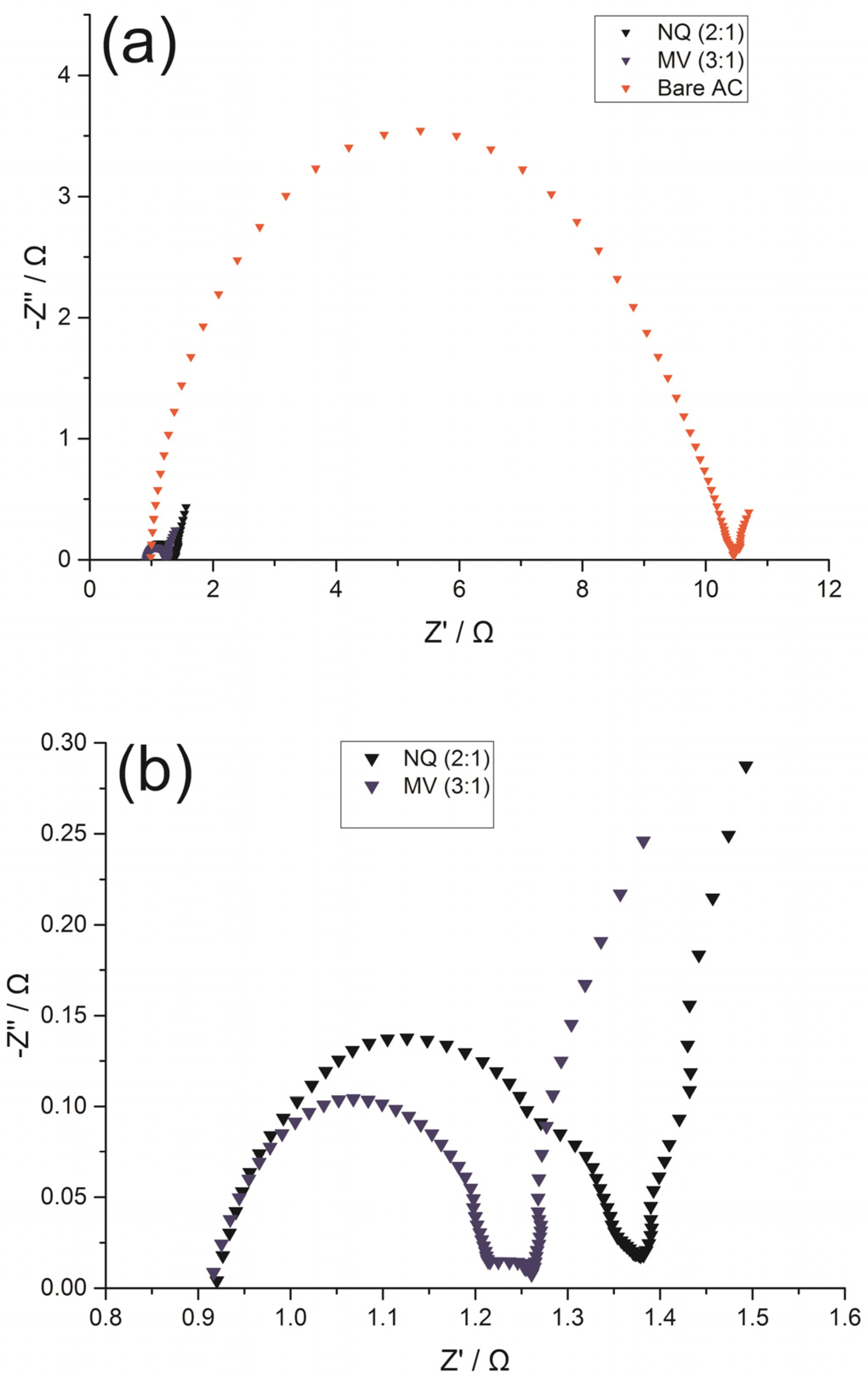
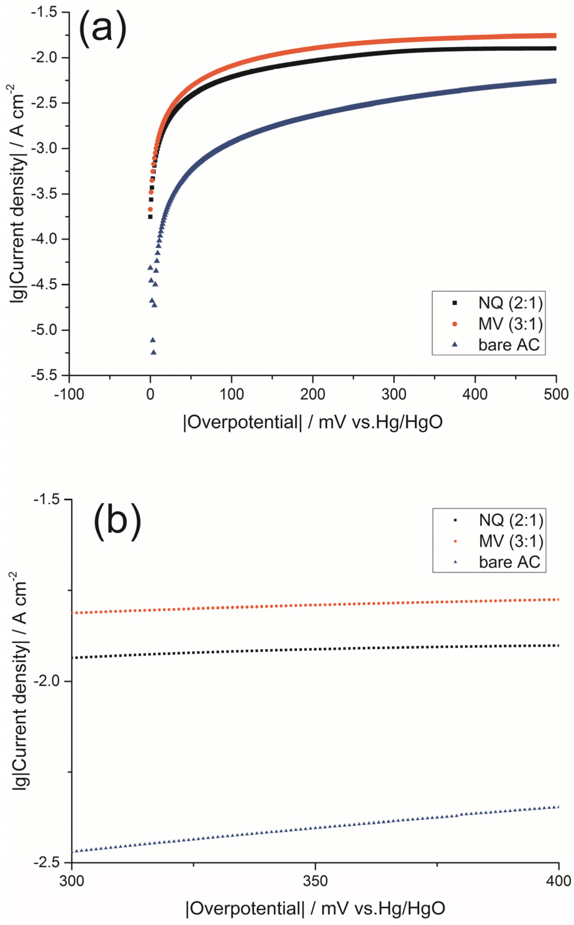
2.3.3. Tafel Curves of the Anodes

Tafel curves of different anodes are shown in Figure 5a. The three curves have the same change trend with the increase of the voltage, exhibiting a steep increase at the beginning then flattening out. There exists a linear Tafel regression (R2 > 0.99) in the over-potential interval of 300 and 400 mV (Figure 5b). The results of linear fitting are showed in Table 3. The exchange current densities are sequenced as follows: MV-AC (3:1) (19.2752 × 10⁻³ Acm−2) > NQ-AC (2:1) (9.3756 × 10⁻³ Acm−2) > bare AC (1.4689 × 10⁻³ Acm−2). A higher value i0 imply a simple and fast reaction with lower activation barrier. It indicates that doping appropriate amount of electron mediators in the AC anode could reduce the resistance and speed up the kinetics, which eventually improve the performance of DGAFC. These results agree with the previous analyses of LSV and EIS.

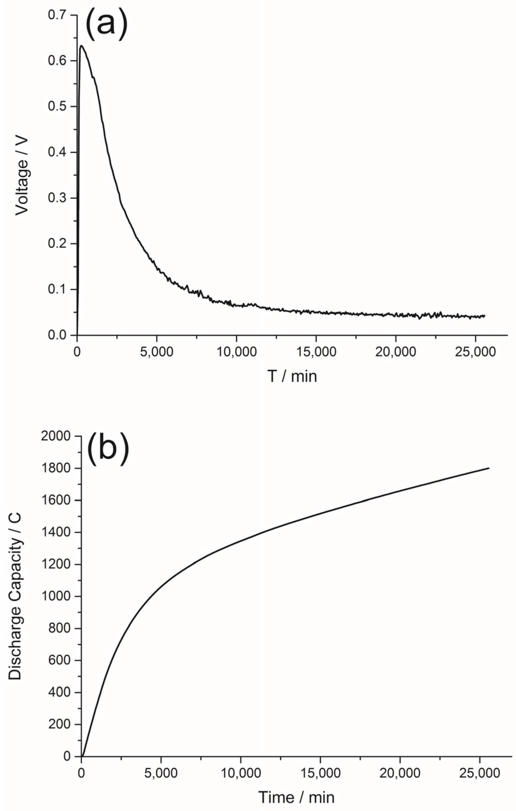
2.4. The Discharge Curve of the DGAFC Equipped with NQ-AC Anode

The discharge curve of DGAFC equipped with a NQ-AC anode and an air-diffusion cathode is shown in Figure 6. The cell can discharge more than 426 h and give a coulomb yield of 1800.84 C under the condition of external resistance of 100 Ω. The circuit voltage across the external resistor increased first and reached the peak voltage of 0.63 V at about 10 h. Finally, the glucose in the anode was used up and the voltage decreased from 0.63 V to less than 0.05 V, gradually. We can attribute such a change in voltage with time to the transformation of glucose and the further oxidation of byproducts as previously reported [25].
NQ is low-cost and has no observable adverse impact to the environment. The combination of NQ and AC composite as anode catalyst for glucose oxidation has better performance than those previously reported [27,29,30]. We believe this work can be a starting point to construct high-performance, cheap, and environmentally friendly DGAFCs.
Table 4 presents the recent studies on similar glucose fuel cells. From the table it can be clearly seen that using NQ/AC anode in our fuel cell can improve its performance compared with other fuel cells equipped with precious metal containing anodes. Furthermore, the fuel cell in our work has the characteristics of low cost, low operating temperature, and a high discharge capacity, which make it a promising candidate to be a portable fuel cell.

3. Experimental Section

3.1. Materials

2-hydroxy-1, 4-naphthoquinone (NQ), anthraquinone (AQ), and MV were all purchased from J&K Scientific Ltd (Beijing, China). 1,5-dichloroanthraquinone (DA), Neutral red (NR), and Methylene blue (MB) were purchased from Tokyo Chemical Industry Co., Ltd. (Tokyo, Japan), Sangon Biological Engineering Co., Ltd. (Beijing, China) and Institute of Chemical Reagents (Tianjin, China), respectively. Carbon cloth (HCP330), 60 wt. % PTFE solution, 10 wt. % platinum on carbon powder (10% Pt on Vulcan XC-72), 5 wt. % Nafion® solution, were all provided by Heshen Inc. (Shanghai, China). Carbon black powder (Cabot Vulcan XC-72, Cabot Co., Ltd, Tianjin, China), AC powder (specific surface area: 1200 m2·g−1), and AEM (ED120, thickness: 0.48 mm, resistance of membrane surface: 18 U cm2) were obtained from Cabot Co., Ltd. (Tianjin, China), North Tianyi Chemical Reagent Factory (Tianjin, China), and Chiaki Environmental Water Treatment Co., Ltd. (Zhejiang, China), respectively. The nickel foam (PPI-70-110) was bought from HANBO Co., Ltd. (Shenzhen, China).

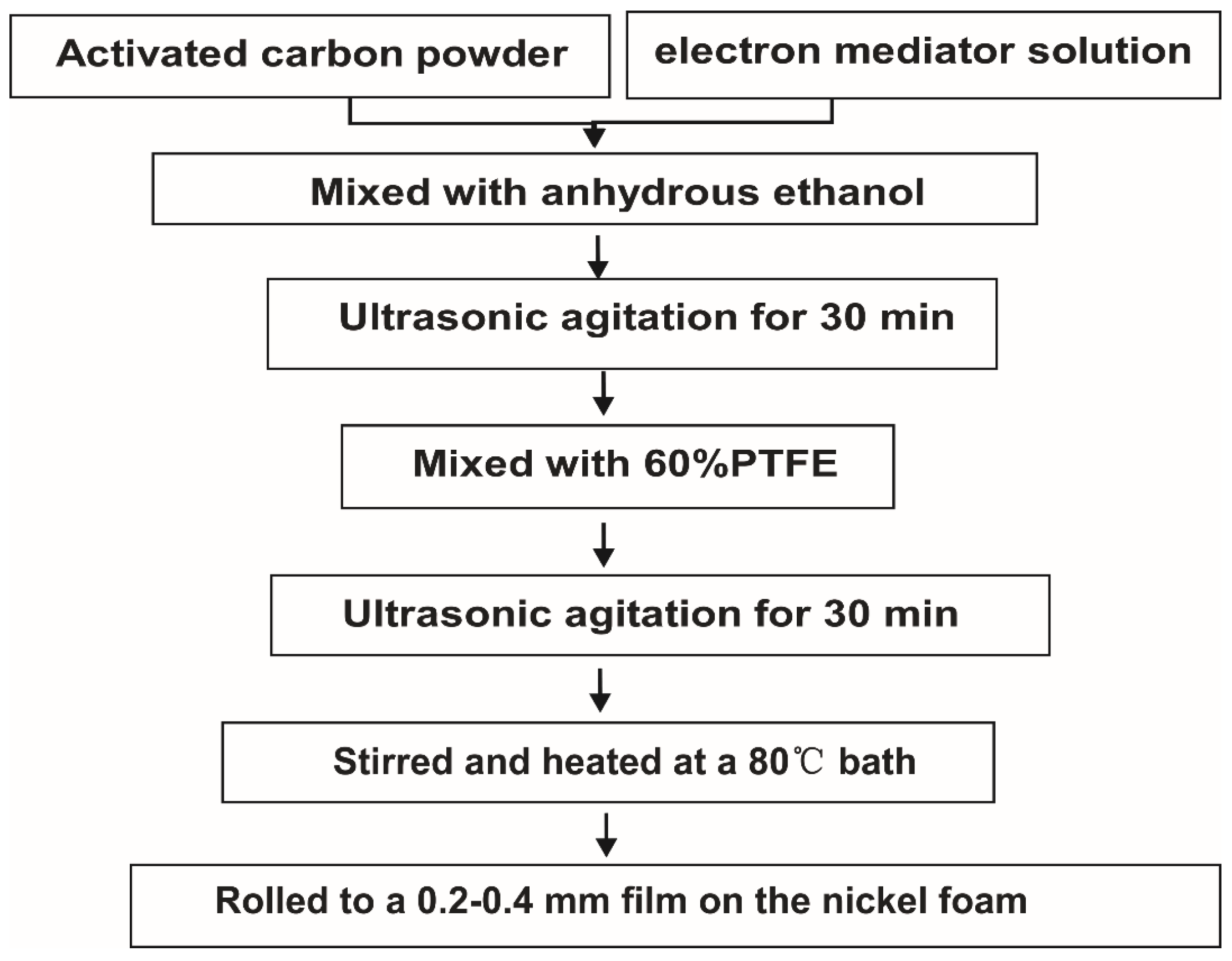
3.2. Preparation of the Electrodes

Figure 7 illustrates the fabrication steps for the electron mediator modified AC anode. Firstly, AC and 30 mM electron mediator solution (mass ratio of AC to electron mediator solution = 1:1–1:3) were mixed thoroughly, then anhydrous ethanol was added until the mixture was submerged more than 1 cm. After that, ultrasonic agitation was conducted for 30 min. Next, 60% PTFE solution was mixed into the solution drop by drop (mass ratio of activated carbon/PTFE = 1:0.5–0.8). We repeated the ultrasonic agitation for another 30 min. Then, heated and stirred the solution in 80 °C water bath until it formed a paste. Finally, the prepared paste was rolled onto a nickel foam to form a thin film of 0.2–0.4 mm. The cathode applied in our study was air-breathing oxygen-reduction cathode that was prepared as previously described [27,29].

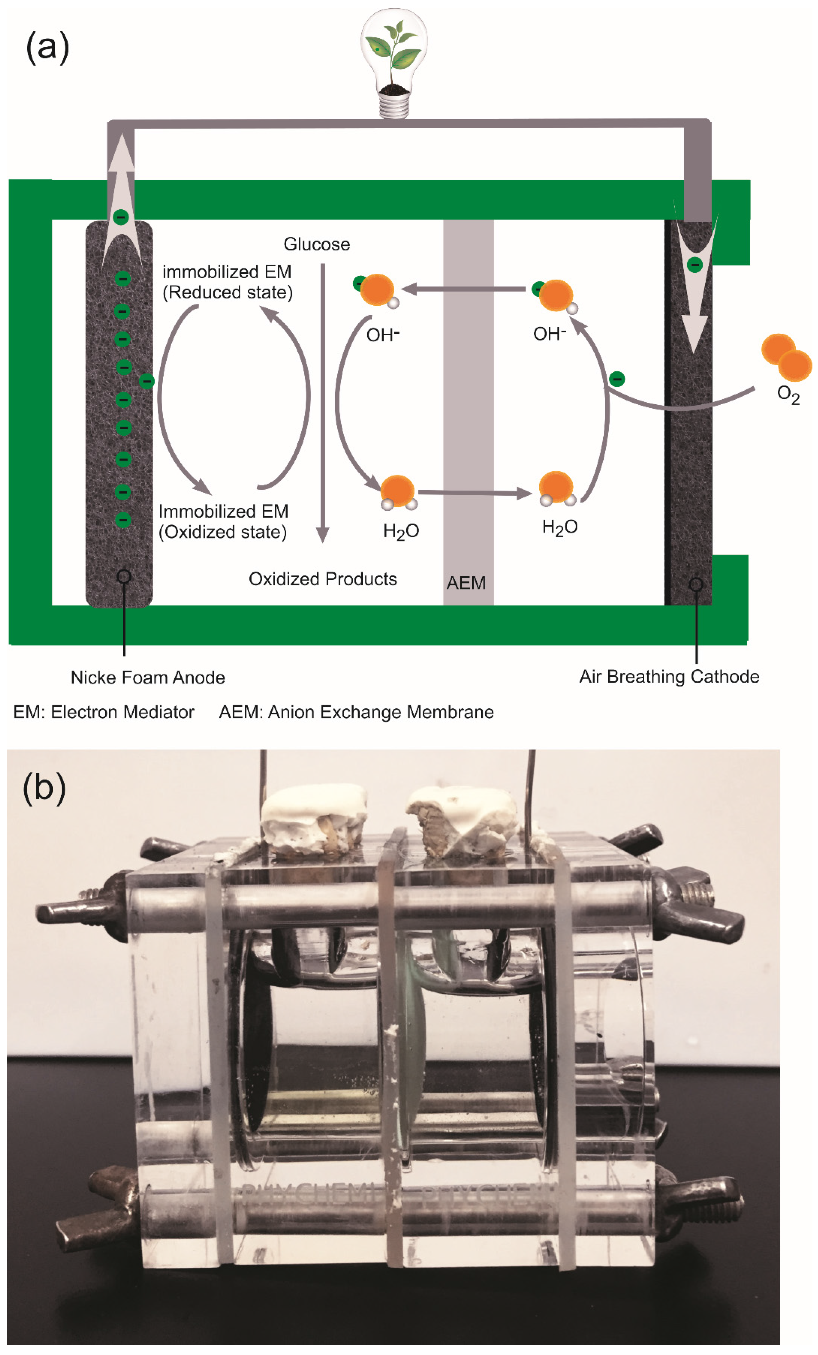
3.3. Fuel Cell Apparatus and Assembly

The polymethyl meth acrylate (PMMA) is used to make the two-chamber fuel cell, and the schematic of the structure and photograph of the fuel cell and is shown in Figure 8a,b. For the air breathing cathode, one side was PTFE diffusion layer which was open to air, while another side called the catalyst layer was submerged under the fuel-electrolyte solution entirely. The fuel cell has two 30 mm-diameter cylindrical internal chambers. The anode chamber was filled with glucose and KOH solution, while the cathode chamber was only full of KOH solution. There was an AEM between the two chambers which had selective conductivity of anions to prevent substrate crossover.

3.4. Electrochemical Analysis

By changing the external resistance from 9000 Ω to 10 Ω, polarization curve and power density curve were achieved. LSV, EIS, and Tafel measurements of all the anodes were conducted on an electrochemical workstation (CHI 660E, Shanghai Chen Hua Instrument Co., Ltd., Shanghai, China) under three electrode systems: different anodes were used as working electrodes respectively, with the Hg/HgO electrode serving as the reference electrode and a platinum sheet used as the counter electrode. EIS was measured at a frequency range of 100 kHz to 10 mHz with amplitude of 5 mV. By sweeping from overpotential of 0 V to 600 mV at scan rate of 1 mVs−1, the Tafel plot was recorded.

4. Conclusions

A two-chamber DGAFC catalyst without noble metal had been developed and tested. Six different electron mediators were immobilized on the AC anode using a simple doping method. Under the condition of 1 M glucose and 3 M KOH, the fuel cell equipped with NQ/AC (2:1) anode generates a peak power density of 16.10 Wm−2, peak current density of 48.09 Am−2 and open circuit voltage of 0.76 V, which is comparable with a DGAFC equipped with an MV-AC anode. The high performance of the NQ/AC anode is likely due to the enhanced charge transfer and more reactive sites provided on the anode. NQ is attractive as an alternative to MV due to its lower toxicity and high catalytic ability for glucose oxidation. These performance data are better than a majority of the existing designs of glucose fuel cells, such as microbial glucose fuel cells and enzymatic fuel cells. Although some problems remain to be solved, such as effect of different AC types and the specific combination of electron mediators on the anode, our proposed fuel cell is of great promise to further promote the commercial application of DGAFCs.

Acknowledgments

This work was partially supported by the Natural Science Foundation of Tianjin City (No. 15JCYBJC21400).

Author Contributions

Z.L. and X.L. conceived and designed the experiments; Z.L. and P.L. carried out the experiments; Z.L., P.Z., and X.L. analyzed the data; Z.L. wrote the paper.

Conflicts of Interest

The authors declare no conflict of interest.

References

  1. Dranga, B.-A.; Lazar, L.; Koeser, H. Oxidation catalysts for elemental mercury in flue gases—A review. Catalysts 2012, 2, 139–170. [Google Scholar] [CrossRef]
  2. Wang, Y.; Zou, S.; Cai, W.-B. Recent advances on electro-oxidation of ethanol on Pt- and Pd-based catalysts: From reaction mechanisms to catalytic materials. Catalysts 2015, 5, 1507–1534. [Google Scholar] [CrossRef]
  3. Lo, K.; Wang, M.Y. Energy conservation in China’s twelfth five-year plan period: Continuation or paradigm shift? Renew. Sustain. Energy Rev. 2013, 18, 499–507. [Google Scholar] [CrossRef]
  4. Balat, M.; Balat, M. Political, economic and environmental impacts of biomass-based hydrogen. Int. J. Hydrog. Energy 2009, 34, 3589–3603. [Google Scholar] [CrossRef]
  5. Weng, Y.; Qiu, S.; Ma, L.; Liu, Q.; Ding, M.; Zhang, Q.; Zhang, Q.; Wang, T. Jet-fuel range hydrocarbons from biomass-derived sorbitol over Ni-HZSM-5/SBA-15 catalyst. Catalysts 2015, 5, 2147–2160. [Google Scholar] [CrossRef]
  6. Urbaniec, K.; Bakker, R.R. Biomass residues as raw material for dark hydrogen fermentation—A review. Int. J. Hydrog. Energy 2015, 40, 3648–3658. [Google Scholar] [CrossRef]
  7. Sopian, K.; Ali, B.; Asim, N. Strategies for renewable energy applications in the organization of Islamic conference (OIC) countries. Renew. Sustain. Energy Rev. 2011, 15, 4706–4725. [Google Scholar] [CrossRef]
  8. Bindig, R.; Butt, S.; Hartmann, I.; Matthes, M.; Thiel, C. Application of heterogeneous catalysis in small-scale biomass combustion systems. Catalysts 2012, 2, 223–243. [Google Scholar] [CrossRef]
  9. Ojala, S.; Koivikko, N.; Laitinen, T.; Mouammine, A.; Seelam, P.; Laassiri, S.; Ainassaari, K.; Brahmi, R.; Keiski, R. Utilization of volatile organic compounds as an alternative for destructive abatement. Catalysts 2015, 5, 1092–1151. [Google Scholar] [CrossRef]
  10. Shabani, S.; Aghajani Delavar, M.; Azmi, M. Investigation of biomass gasification hydrogen and electricity co-production with carbon dioxide capture and storage. Int. J. Hydrog. Energy 2013, 38, 3630–3639. [Google Scholar] [CrossRef]
  11. Schechner, P.; Kroll, E.; Bubis, E.; Chervinsky, S.; Zussman, E. Silver-plated electrospun fibrous anode for glucose alkaline fuel cells. J. Electrochem. Soc. 2007, 154, B942–B948. [Google Scholar] [CrossRef]
  12. An, L.; Zhao, T.S.; Shen, S.Y.; Wu, Q.X.; Chen, R. Alkaline direct oxidation fuel cell with non-platinum catalysts capable of converting glucose to electricity at high power output. J. Power Sour. 2011, 196, 186–190. [Google Scholar] [CrossRef]
  13. Liang, B.; Guo, X.; Fang, L.; Hu, Y.; Yang, G.; Zhu, Q.; Wei, J.; Ye, X. Study of direct electron transfer and enzyme activity of glucose oxidase on graphene surface. Electrochem. Commun. 2015, 50, 1–5. [Google Scholar] [CrossRef]
  14. Kumar, R.; Leech, D. A glucose anode for enzymatic fuel cells optimized for current production under physiological conditions using a design of experiment approach. Bioelectrochemistry 2015, 106, 41–46. [Google Scholar] [CrossRef] [PubMed]
  15. Lee, Y.-Y.; Kim, T.G.; Cho, K.-S. Effects of proton exchange membrane on the performance and microbial community composition of air-cathode microbial fuel cells. J. Biotechnol. 2015, 211, 130–137. [Google Scholar] [CrossRef] [PubMed]
  16. Kirubaharan, C.J.; Santhakumar, K.; Gnana kumar, G.; Senthilkumar, N.; Jang, J.-H. Nitrogen doped graphene sheets as metal free anode catalysts for the high performance microbial fuel cells. Int. J. Hydrog. Energy 2015, 40, 13061–13070. [Google Scholar] [CrossRef]
  17. Hernández-Fernández, F.J.; Pérez de los Ríos, A.; Salar-García, M.J.; Ortiz-Martínez, V.M.; Lozano-Blanco, L.J.; Godínez, C.; Tomás-Alonso, F.; Quesada-Medina, J. Recent progress and perspectives in microbial fuel cells for bioenergy generation and wastewater treatment. Fuel Process. Technol. 2015, 138, 284–297. [Google Scholar] [CrossRef]
  18. Fujiwara, N.; Yamazaki, S.-I.; Siroma, Z.; Ioroi, T.; Senoh, H.; Yasuda, K. Nonenzymatic glucose fuel cells with an anion exchange membrane as an electrolyte. Electrochem. Commun. 2009, 11, 390–392. [Google Scholar] [CrossRef]
  19. Gu, Y.; Liu, Y.; Yang, H.; Li, B.; An, Y. Electrocatalytic glucose oxidation via hybrid nanomaterial catalyst of multi-wall TiO2 nanotubes supported Ni(OH)2 nanoparticles: Optimization of the loading level. Electrochim. Acta 2015, 160, 263–270. [Google Scholar] [CrossRef]
  20. Ramsurn, H.; Gupta, R.B. Nanotechnology in solar and biofuels. ACS Sustain. Chem. Eng. 2013, 1, 779–797. [Google Scholar] [CrossRef]
  21. Liu, C.; Burghaus, U.; Besenbacher, F.; Wang, Z.L. Preparation and characterization of nanomaterials for sustainable energy production. ACS Nano 2010, 4, 5517–5526. [Google Scholar] [CrossRef] [PubMed]
  22. Apblett, C.A.; Ingersoll, D.; Sarangapani, S.; Kelly, M.; Atanassov, P. Direct glucose fuel cell: Noble metal catalyst anode polymer Electrolyte Membrane fuel cell with Glucose Fuel. J. Electrochem. Soc. 2010, 157, B86–B89. [Google Scholar] [CrossRef]
  23. Zhao, C.X.; Wang, K.; Yan, H.; Xu, G. Output current increase in alkaline glucose fuel cells. J. Electrochem. Soc. 2011, 158, B1055–B1059. [Google Scholar] [CrossRef]
  24. Basu, D.; Basu, S. A Study on Direct Glucose and Fructose Alkaline Fuel Cell. Electrochim. Acta 2010, 55, 5775–5779. [Google Scholar] [CrossRef]
  25. Chen, J.; Zhao, C.X.; Zhi, M.M.; Wang, K.; Deng, L.; Xu, G. Alkaline direct oxidation glucose fuel cell system using silver/nickel foams as electrodes. Electrochim. Acta 2012, 66, 133–138. [Google Scholar] [CrossRef]
  26. Zhang, D.; Popov, B.N.; White, R.E. Electrochemical investigation of CRO 2.65 doped LiMn2O4 as a cathode material for lithium-ion batteries. J. Power Sour. 1998, 99, 466–472. [Google Scholar]
  27. Yang, Y.-L.; Liu, X.-H.; Hao, M.-Q.; Zhang, P.-P. Performance of a low-cost direct glucose fuel cell with an anion-exchange membrane. Int. J. Hydrog. Energy 2015, 40, 10979–10984. [Google Scholar] [CrossRef]
  28. Chen, X.Y.; He, Y.Y.; Song, H.; Zhang, Z.J. Structure and electrochemical performance of highly nanoporous carbons from benzoate-metal complexes by a template carbonization method for supercapacitor application. Carbon 2014, 72, 410–420. [Google Scholar] [CrossRef]
  29. Liu, X.; Hao, M.; Feng, M.; Zhang, L.; Zhao, Y.; Du, X.; Wang, G. A one-compartment direct glucose alkaline fuel cell with methyl viologen as electron mediator. Appl. Energy 2013, 106, 176–183. [Google Scholar] [CrossRef]
  30. Eustis, R.; Tsang, T.M.; Yang, B.; Scott, D.; Liaw, B.Y. Seeking effective dyes for a mediated glucose-air alkaline battery/fuel cell. J. Power Sour. 2014, 248, 1133–1140. [Google Scholar] [CrossRef]
Figure 1. Polarization curves (a) and power density curves (b) of DGAFCs with AC anodes doped with different electron mediators under the condition of 1 M glucose and 3 M KOH.
Catalysts 06 00095 g001
Figure 2. Polarization curves (a) and power density curves (b) of DGAFCs equipped with AC anodes fabricated with MV/AC; polarization curves (c) and power density curves (d) of DGAFCs equipped with AC anodes fabricated with NQ/AC under the condition of 1 M glucose and 3 M KOH.
Catalysts 06 00095 g002
Figure 3. LSV polarization curves of the bare AC anode, NQ/AC (2:1) anode, and MV/AC (3:1) anode under the condition of 1 M glucose and 3 M KOH.
Catalysts 06 00095 g003
Figure 4. Nyquist plots of EIS by bare AC, NQ/AC (2:1) and MV/AC (3:1) anodes (a); as well as the magnified ones (b).
Catalysts 06 00095 g004
Figure 5. Tafel plots of different anodes (a) and enlarged scale graph for the Tafel plots of overpotential from 300 mV to 400 mV (b).
Catalysts 06 00095 g005
Figure 6. Curves of voltage versus time (a) and discharge curves (b) of the DGAFC under the condition of 1 M glucose, 3 M KOH.
Catalysts 06 00095 g006
Figure 7. Fabrication procedures for the immobilized activated carbon anode.
Catalysts 06 00095 g007
Figure 8. Schematic of the structure (a) and photograph (b) of the two-chamber DGAFC.
Catalysts 06 00095 g008
Table 1. Comparison of six compounds to function as electron mediators: molar mass, molecular structure, molecular formula, soluble in ethanol solution, market prices, and their corresponding fuel cell performance.
Compound NameMolar Mass (g·mol−1)Molecular StructureMolecular FormulaSoluble in EthanolMarket Price (RMB/g)OCV a (V)PPD b (Wm−2)PCD c (Am−2)
NR288.78 Catalysts 06 00095 i001C15H17ClN4Yes0.50.817.3929.08
NQ174.15 Catalysts 06 00095 i002C10H6O3Yes150.799.9534.23
DA277.10 Catalysts 06 00095 i003C14H6Cl2O2No120.737.0714.31
MB319.85 Catalysts 06 00095 i004C16H18ClN3SYes10.799.3722.90
AQ208.22 Catalysts 06 00095 i005C14H8O2No40.736.7013.43
MV257.16 Catalysts 06 00095 i006C12H14Cl2N2Yes2000.7810.0525.61
a OCV: open cell voltage; b PPD: peak power density; c PCD: peak current density.
Table 2. Electrochemical impedance fitting results of different anodes.
ResistanceBare ACNQ (2:1)MV (3:1)
Ro(Ω)0.98910.90440.9182
Rct(Ω)8.97200.45220.3101
Rd(Ω)0.07790.07480.0786
Table 3. Exchange current density calculated from the Tafel plots.
The AnodeLinear Fitting Equation (R2)10−3 i0 (Acm−2)
bare ACy = −2.833 + 0.001x (0.998)1.4689
NQ (2:1)y = −2.028 + 0.00006x (0.995)9.3756
MV (3:1)y = −1.715 + 0.00009 x (0.991)19.2752
Table 4. Recent reports on similar fuel cells.
Anode CatalystRef.OCV (V)PPD (W/m2)Room TemperatureDischarge Capacity (C)Glucose Conc. (M)
NQ/AC/NiThis work0.7916.10Yes1800.841.00
Ag[11]0.391.96Yes-0.80
Ni[23]-0.14Yes-0.50
PtRu/C[24]0.9013.8030 °C-0.20
Ag/Ni[25]-20.3080 °C-1.00
Ni[27]0.755.2Yes153.581.00

