Article

Synthesis and Electrochemical Evaluation of Carbon Supported Pt-Co Bimetallic Catalysts Prepared by Electroless Deposition and Modified Charge Enhanced Dry Impregnation

by
John Meynard M. Tengco
1,
Bahareh Alsadat Tavakoli Mehrabadi
1,
Yunya Zhang
1,
Akkarat Wongkaew
2,
John R. Regalbuto
1,
John W. Weidner
1 and
John R. Monnier
1,*
1
Department of Chemical Engineering, College of Engineering and Computing, University of South Carolina, 301 Main St., Columbia, SC 29208, USA
2
Department of Chemical Engineering, Faculty of Engineering, Burapha University, Chonburi 20131, Thailand
*
Author to whom correspondence should be addressed.
Catalysts 2016, 6(6), 83; https://doi.org/10.3390/catal6060083
Submission received: 31 March 2016 / Revised: 27 May 2016 / Accepted: 2 June 2016 / Published: 7 June 2016
(This article belongs to the Special Issue Rational Synthesis of Supported Bimetallic Catalysts)

Abstract

:
Carbon-supported bimetallic Pt-Co cathode catalysts have been previously identified as higher activity alternatives to conventional Pt/C catalysts for fuel cells. In this work, a series of Pt-Co/C catalysts were synthesized using electroless deposition (ED) of Pt on a Co/C catalyst prepared by modified charge enhanced dry impregnation. X-ray diffraction (XRD) and scanning transmission electron microscopy (STEM) characterization of the base catalyst showed highly dispersed particles. A basic ED bath containing PtCl62− as the Pt precursor, dimethylamine borane as reducing agent, and ethylenediamine as stabilizing agent successfully targeted deposition of Pt on Co particles. Simultaneous action of galvanic displacement and ED resulted in Pt-Co alloy formation observed in XRD and energy dispersive X-ray spectroscopy (XEDS) mapping. In addition, fast deposition kinetics resulted in hollow shell Pt-Co alloy particles while particles with Pt-rich shell and Co-rich cores formed with controlled Pt deposition. Electrochemical evaluation of the Pt-Co/C catalysts showed lower active surface but much higher mass and surface activities for oxygen reduction reaction compared to a commercial Pt/C fuel cell catalyst.

Graphical Abstract

1. Introduction

Successful commercial adaptation of fuel cells is very much reliant on the economic viability of this technology. Proton exchange fuel cells (PEMFCs) are highly considered for wide scale use in small form factor applications such as vehicles and mobile technology owing to their high performance and compact design. Improving the cost competitiveness of PEMFCs can be done by enhancing the activity and durability of the catalyst employed [1,2]. One of the most widely used catalysts for electrochemical (i.e., oxygen reduction reaction, ORR) applications is a carbon-supported platinum catalyst (Pt/C) which has well-recognized issues with activity degradation from particle instability and corrosion of the metal and support. Increasing catalyst activity can be done by synthesizing smaller particle sizes to achieve greater metal dispersion, where dispersion is defined as the fraction of the metal atoms exposed on the surface. Various methods have been developed to increase metal dispersion specially for Pt/C catalysts, however there are also arguments against smaller Pt particles in ORR catalysts as some studies have pointed to lower specific activity for highly dispersed (50%–100%) platinum for ORR applications [3,4,5]. Catalyst durability on the other hand largely depends on the stability of the metal-support system, mainly to the resistance of the metal towards sintering and corrosion in the electrochemical system. While smaller Pt particles may have higher active site concentrations for a given weight loading, they tend to sinter more easily giving larger particles with lower active site concentrations. One way to improve the durability of Pt fuel cell catalysts is by anchoring particles on the support with a different metal that is more resistant to sintering, such as Pd or Co, or by forming Pt alloys with the second metals that have higher corrosion resistance [6,7,8]. The formation of alloyed Pt-M bimetallic catalysts, where M is another transition metal, can also increase catalyst activity, particularly with the Pt-Co system [6,8,9]. These results have been corroborated in density functional theory studies which concluded that a bimetallic surface is needed for better fuel cell catalyst design [10,11,12]. Specifically, direct electronic interactions between the two metals can increase the electron density at the Pt site to improve the dissociative adsorption of O2. Alternatively, pseudo-epitaxial deposition of thin layers of Pt on the second metal (typically Co) can give compression of the overlying Pt lattice (shorter Pt-Pt bonds) to increase the rate of O–O bond dissociation.
The conventional choice of method for commercial preparation of metallic catalysts is simple impregnation of an aqueous solution of a metal precursor salt into the pores of the support. This straightforward method often results in poor dispersion of the final metal particles and a wide distribution of particle sizes. Extending this method to bimetallic catalysts also results in poor distribution of the component metals and forms fractions of both monometallic components as well as bimetallic particles with a wide range of compositions. The bimetallic particles can also be considered as bulk compositions, with little knowledge of the actual surface components. The methods of strong electrostatic adsorption (SEA) and its incipient wetness analog, charge enhanced dry impregnation (CEDI) have been used for the preparation of well dispersed catalysts with narrow size distributions [13,14]. The manipulation of impregnation pH during SEA induces a charge on the surface of the support by protonation or deprotonation of surface functional groups depending on the point of zero charge of the support [15]. In effect, the charged surface electrostatically adsorbs an oppositely charged precursor complex wherein the strong complex-support interaction decreases mobility during thermal treatment to facilitate small particle formation. For the formation of bimetallic catalysts, the method of electroless deposition (ED) has been shown to form true bimetallic catalysts with no particles of each of the monometallic components [16,17,18,19]. Further, because the first step in ED is the activation of a solution phase reducing agent on the surface of the base catalyst particles, there is targeted reduction of the secondary metal salt in solution (catalytic or auto-catalytic deposition) to form surfaces with known compositions of each metal.
The use of SEA and ED methods have been previously demonstrated for preparation of bimetallic fuel cell catalysts [13,17,20,21,22,23,24]. Specifically, ED has been previously used for preparation of a family of Pt-Co bimetallic PEMFC catalysts, where different amounts of Pt were deposited on the surface of cobalt particles [20]. The Co catalyst was prepared by impregnation of CoCl2 on the carbon support to give Co particles varied in size from 3–15 nm in diameter. This work extends those previous studies by reformulation of the electroless developer bath and using Pt loadings lower than those commonly used in commercial samples. Charge enhanced dry impregnation (CEDI) was used to prepare the Co core component to give well-dispersed and uniform sized particles as the base catalyst for ED of Pt. The catalysts have been well-characterized and evaluated for oxygen reduction reaction (ORR) performance. Results are compared with a commercially-available, high Pt loading catalyst.

2. Results and Discussion

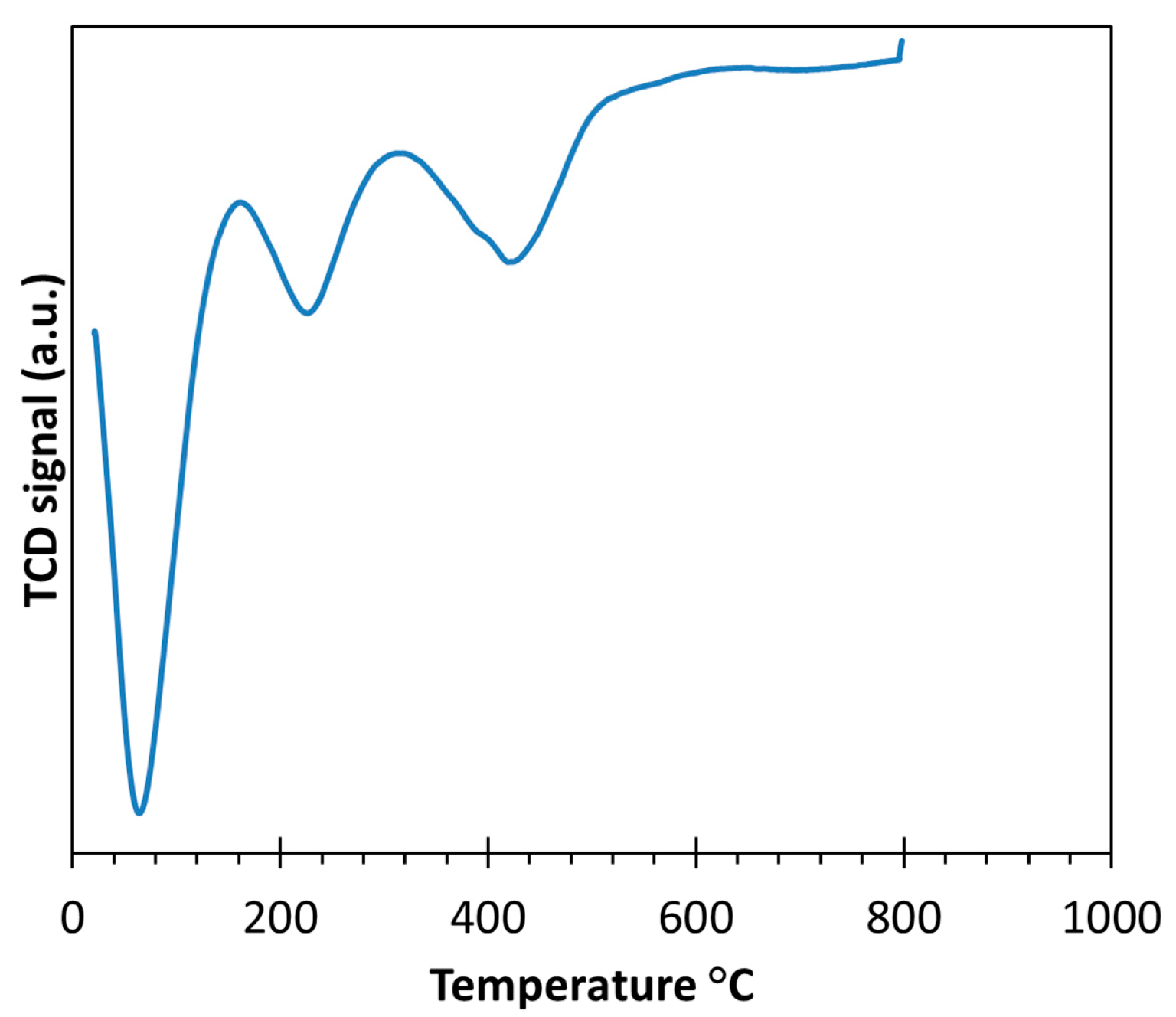
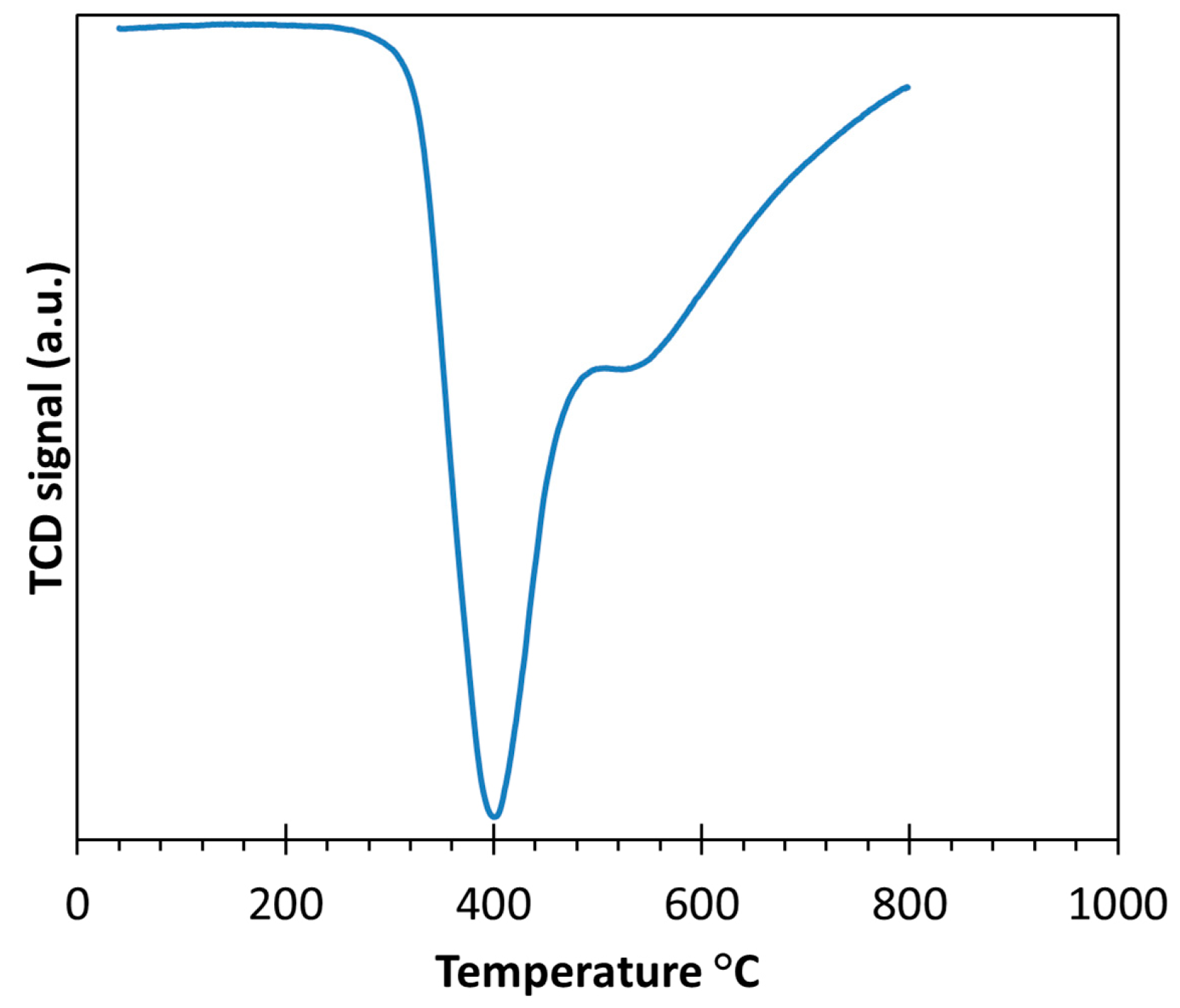
2.1. Thermal Treatment and Dispersion of Co/C Base Catalyst

Temperature programmed analyses of the cobalt-impregnated carbon were done on the sample with 5.0 wt % Co/C loading to increase the concentration of products to be detected by the thermal conductivity detector (TCD). During the temperature programmed decomposition (TPD) in flowing He of the impregnated carbon support, expectations were that exposure to elevated temperatures in flowing inert gas should cause decomposition of the Co(NO3)2 component to form Co3O4 and N2, while the citric acid additive should decompose to form CO2 and H2O. The inverse peaks of the TPD profile in Figure 1 show thermal conductivity changes of the flowing He where the primary and most intense peak at approximately 60 °C is attributed to water evolution while the second peak is associated with evolution of CO2 and N2 as decomposition products. The second and third peaks at 220–250 °C and 420–440 °C, respectively, may be due to decomposition products such as N2, CO2, and H2O; the actual compositions could not be identified because of the non-selective nature of the thermal conductivity detector. The highest temperature peak at 420–440 °C may also include CO2 formed from oxidation of the carbon support from reaction with Co oxide(s) particles. Because of the possibility of support oxidation and the observation that major decomposition events occurred below 250 °C, the annealing temperature was set at 250 °C for all compositions.
The temperature programmed reduction (TPR) profile of the annealed sample is shown in Figure 2. The strong inverse peak centered at 400 °C is associated with the reduction of unspecified cobalt oxide particles to form H2O and Co°. This reduction temperature agrees well with Co oxide reduction observed by others for carbon-supported cobalt [25,26] and was chosen as the temperature for bulk reduction of Co oxide. The small, broad shoulder between 500–600 °C can be associated with Co0-assisted hydrogenation of the carbon support to methane [27,28]. This temperature region should be avoided to minimize alteration of the support surface; thus, reduction temperatures for all compositions were limited to 400 °C.
Determination of Co particle sizes for the reduced catalysts was necessary for ED experiments to approximate the coverages of Pt on the Co surface. However, H2 chemisorption for Co is very unreliable due to the reversibility of adsorbed H [29]. Thus, Co particle sizes were determined using X-ray diffraction (XRD). The XRD profiles of the freshly-reduced 2.5 wt % Co/C and 5.0 wt % Co/C samples are shown in Figure 3; the profiles for both loadings are virtually identical. By careful deconvolution of the Co° peak (2θ = 44.2°) from the most prominent peak of Co3O4 (2θ = 36.9°) and subsequent use of the Scherrer equation, an average Co particle diameter of 1.6 nm was calculated for both Co loadings. For corroboration, high-angle annular dark-field scanning transmission electron microscopy (HAADF-STEM) micrographs of the 5.0 wt % Co/C sample were acquired and a representative image is shown in Figure 4. Contrast of Co particles to that of the support is weak; however, the outlines of the particles can still be made and, using visual estimation, correspond to about 2 nm particles, in good agreement with XRD determination. The 1.6 nm particle size was then used to calculate Co dispersion assuming hemispherical particles to yield a surface Co site concentration of 1.5 × 10²⁰ atoms per gram of catalyst.
The Co particle size of 1.6 nm is very appropriate for ED since a thin shell of Pt should give a high concentration of Pt surface sites. The small particle size is attributed to the wetting effect of the citric acid on the carbon support which has two modes to aid the mechanism of small particle generation. Firstly, the interaction of citric acid with the support protonates the surface of the carbon [13,14], and secondly, the resulting citrate anion complexes Co2+ to form an anionic species [30,31] to induce the strong electrostatic interaction between the anionic cobalt citrate complex and the positively-charged carbon surface. Since SEA is limited to a sterically-limited, close packed monolayer of the ionic complex (including the hydration sheath) [15], the loading of Co is limited by the surface area of the support and the size of the hydrated ionic complex. For this study, the cobalt loadings for 5.0 wt % Co and 2.5 wt % Co correspond to 2.8 µmol/m2 of surface and 1.4 µmol/m2 of surface, respectively, which are higher than normally used for transition metal uptakes and may account for the resulting particle sizes that are larger than those usually observed for SEA (<1 nm particles). Still, the particles are small and as the STEM images in Figure 4 indicate the distribution of sizes is quite narrow.

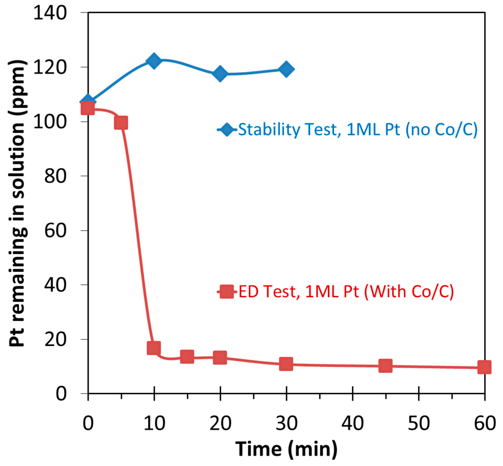
2.2. Bimetallic Pt-Co/C Catalysts from Electroless Deposition Experiments

Preliminary bath stability experiments showed that the ED bath at 50 °C containing the [PtCl6]2− platinum precursor, dimethylamine borane (DMAB) reducing agent, and the EN stabilizer at a molar ratio of 1:5:4 was unstable above 120 ppm Pt. The instability was marked by a change from a clear pale yellow solution to dark brown coloration of the solution within five minutes of the experiment. This is due to the reduction of PtCl62− to Pt0 in solution which was confirmed by atomic absorption spectrometry (AAS) analysis of the filtered solution that showed loss of water-soluble PtCl62− after reduction to Pt0 occurred. However, similar experiments showed that PtCl62− concentrations <120 ppm (based on Pt) were stable in solution for at least 30 min.
Addition of Co/C to the bath resulted in catalytic reduction of PtCl62− that was completed in less than 15 min of exposure. A representative profile of PtCl62− concentration in solution during stability testing and electroless deposition of sufficient Pt to deposit 1 ML (one monolayer) of monodisperse coverage of Pt on Co is shown in Figure 5. The decrease in PtCl62− in solution was due to ED of Pt on the cobalt surface, and not electrostatic adsorption of PtCl62− on the carbon support. The bath pH (pH 10) was well above the point of zero charge (PZC) of the carbon support, meaning the carbon surface was deprotonated to give a net negative charge; previous work had shown the PZC was pH 3.4. The net negative charge on the surface repels the anionic PtCl62− complex [15]. Thus, as shown in previous studies the choice of precursor ion and pH of the solution appropriate for the PZC of the support effectively targets the deposition of the secondary metal only on the surface of the surface of the base catalyst [17,23] and not on the support.
Analysis of the bath after ED experiments showed that there was also loss of cobalt into the solution. The cobalt leaching was observed as a pink coloration of the filtered solution, indicative of a Co2+ species, possibly as a cobalt-ethylenediamine complex [32]. Cobalt leaching was also observed in other ED experiments where pink coloration of the filtrate was observed approximately 15 min after addition of the Co/C catalyst, corresponding to complete PtCl62− deposition. It is likely that in addition to ED of Pt, galvanic displacement (GD) of Co0 by Pt also occurred. For GD to occur, there must be a favorable redox potential for the oxidation of the primary metal from the base catalyst (Co0, in this case) and the reduction of the secondary metal ion from the precursor (Pt4+) [33,34,35,36]. Calculation of the cell potential for the oxidation of Co0 to form Co2+ and the reduction of PtCl62− to form Pt0 + 6Cl, shown in Equation (1), gives a net potential of 2.038 V [37]. This positive cell potential indicates a spontaneous redox reaction can occur and that the moles of Co oxidized will be twice the moles of Pt reduced. Thus, both ED and GD of the platinum on the base catalyst can and likely does occur. This GD resulted in substantially lowered cobalt content in the final catalyst as shown in the calculated metal loadings after the ED experiments in Table 1.
Co 0 Co 2 + + 2 e + 0.277   V PtCl 6 2 + 4 e Pt 0 + 6 Cl + 1.484   V 2 Co 0 + PtCl 6 2 2 Co 2 + + Pt 0 + 6 Cl + 2.038   V

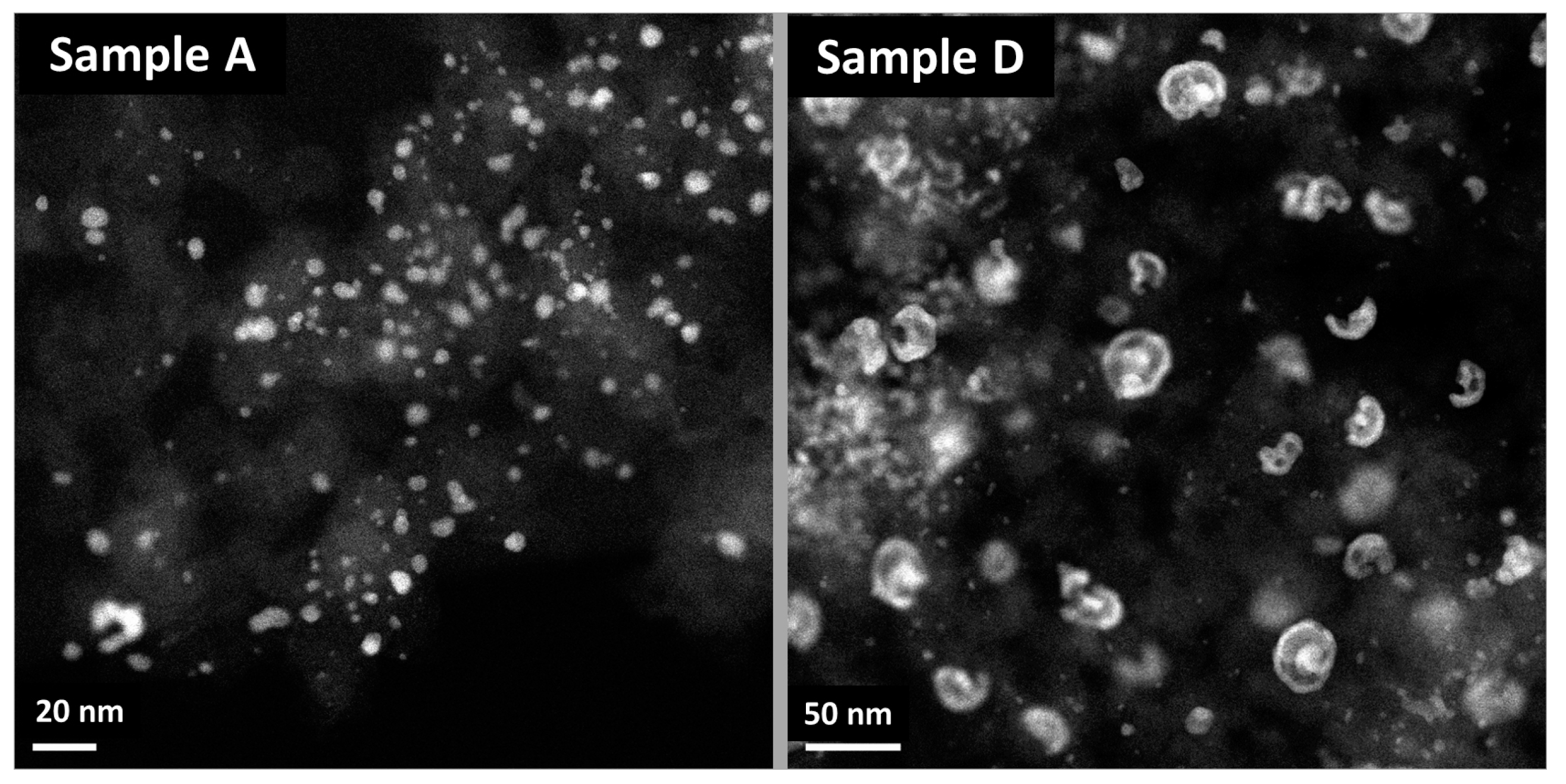
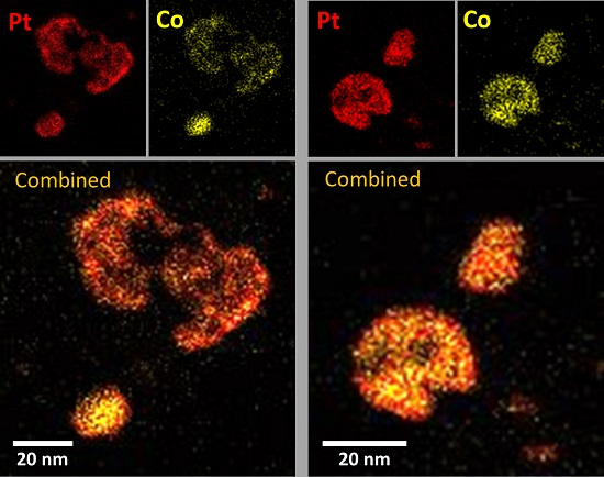
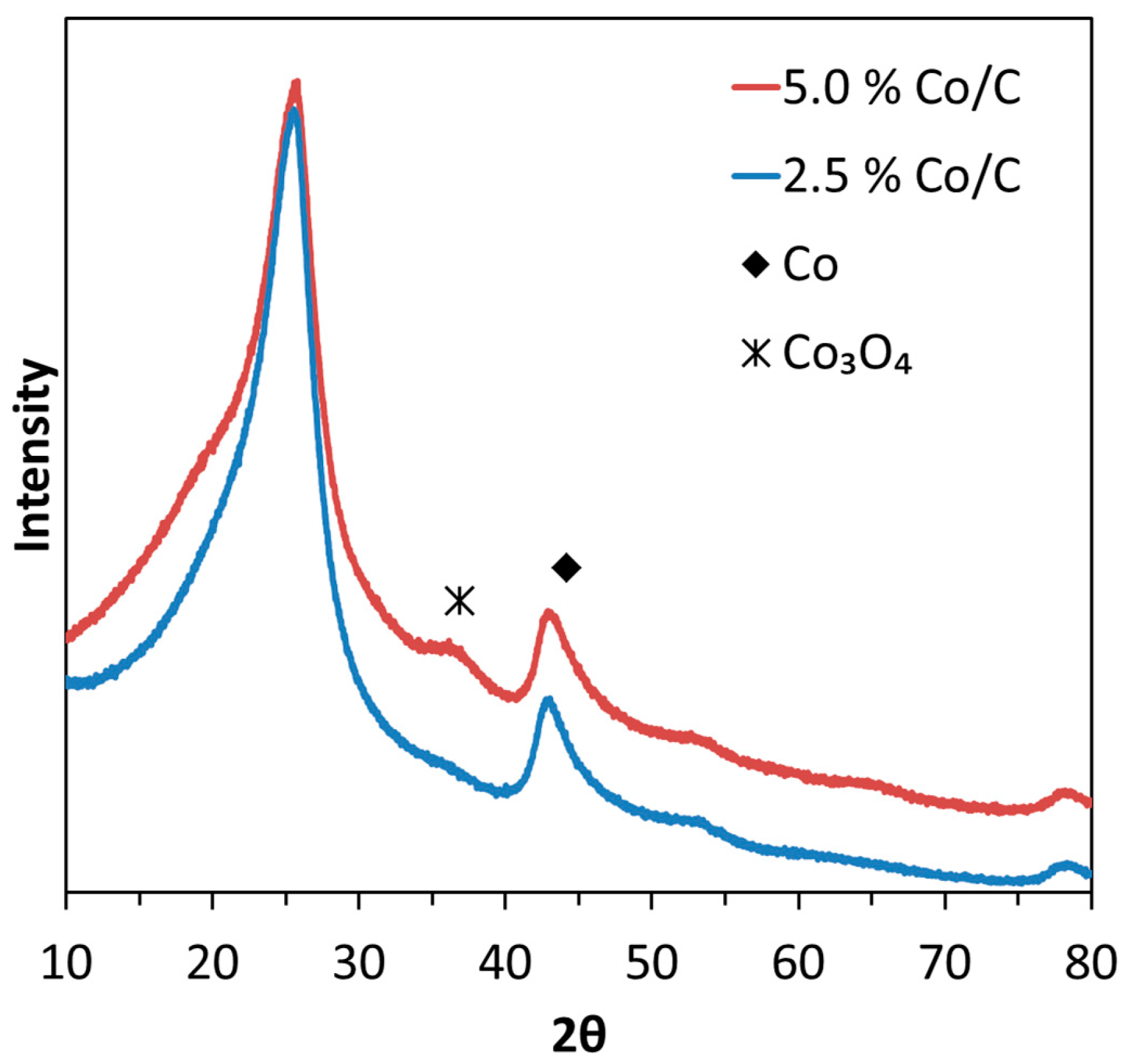
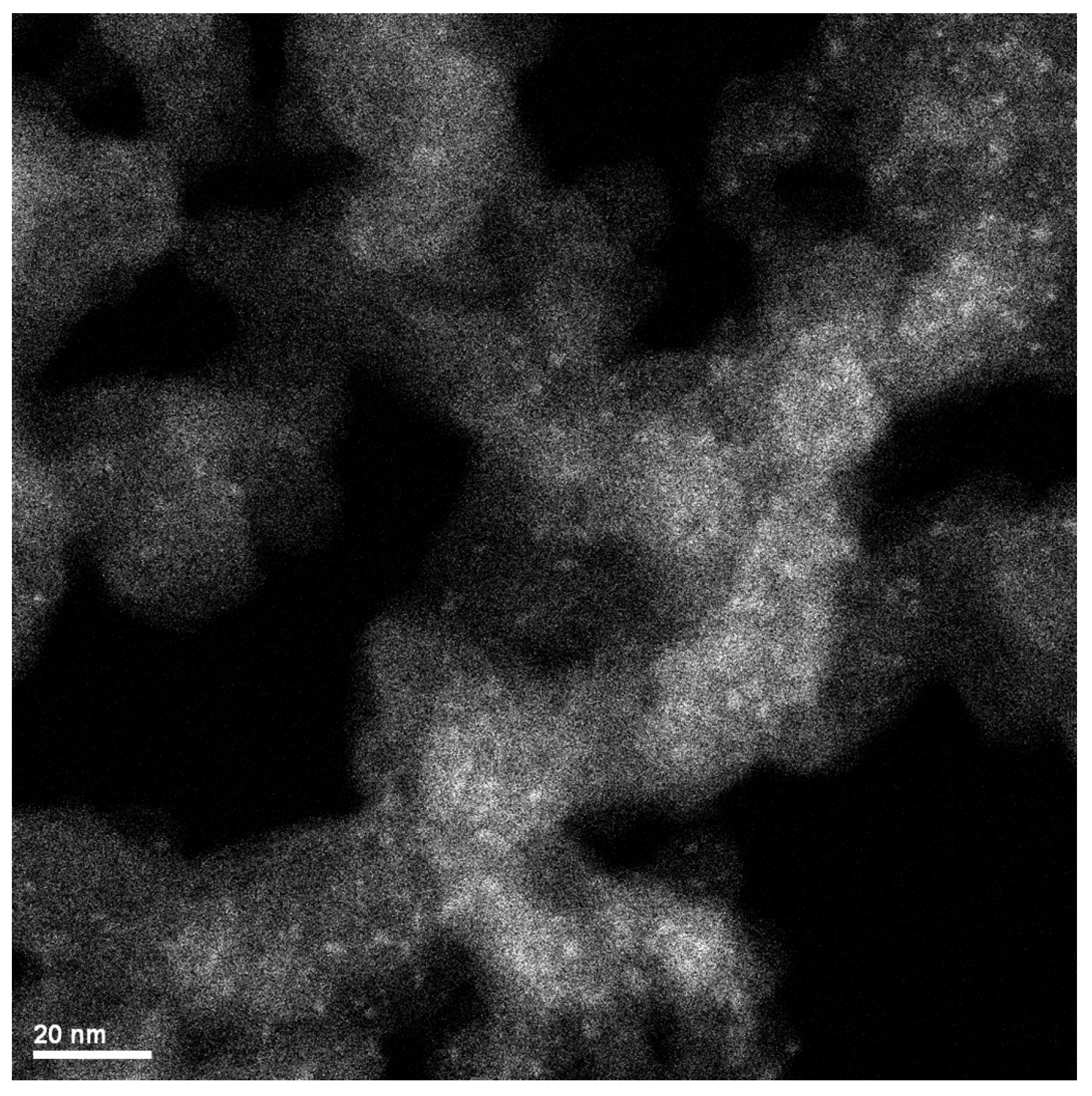
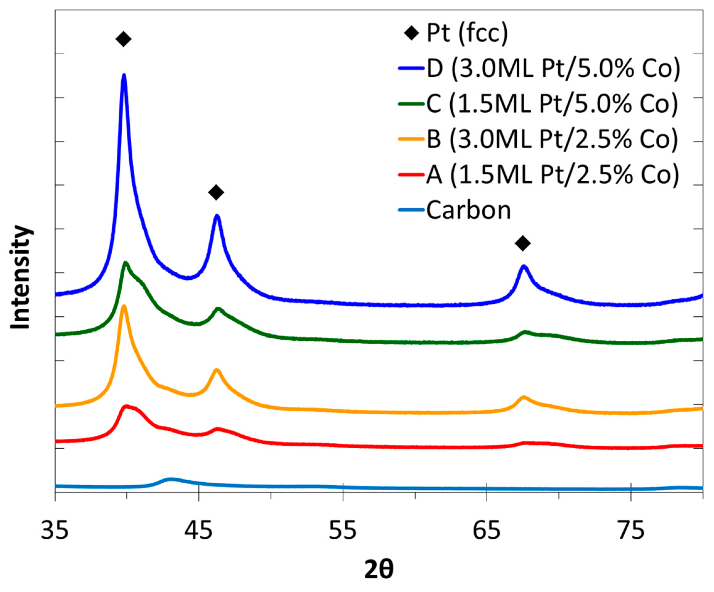
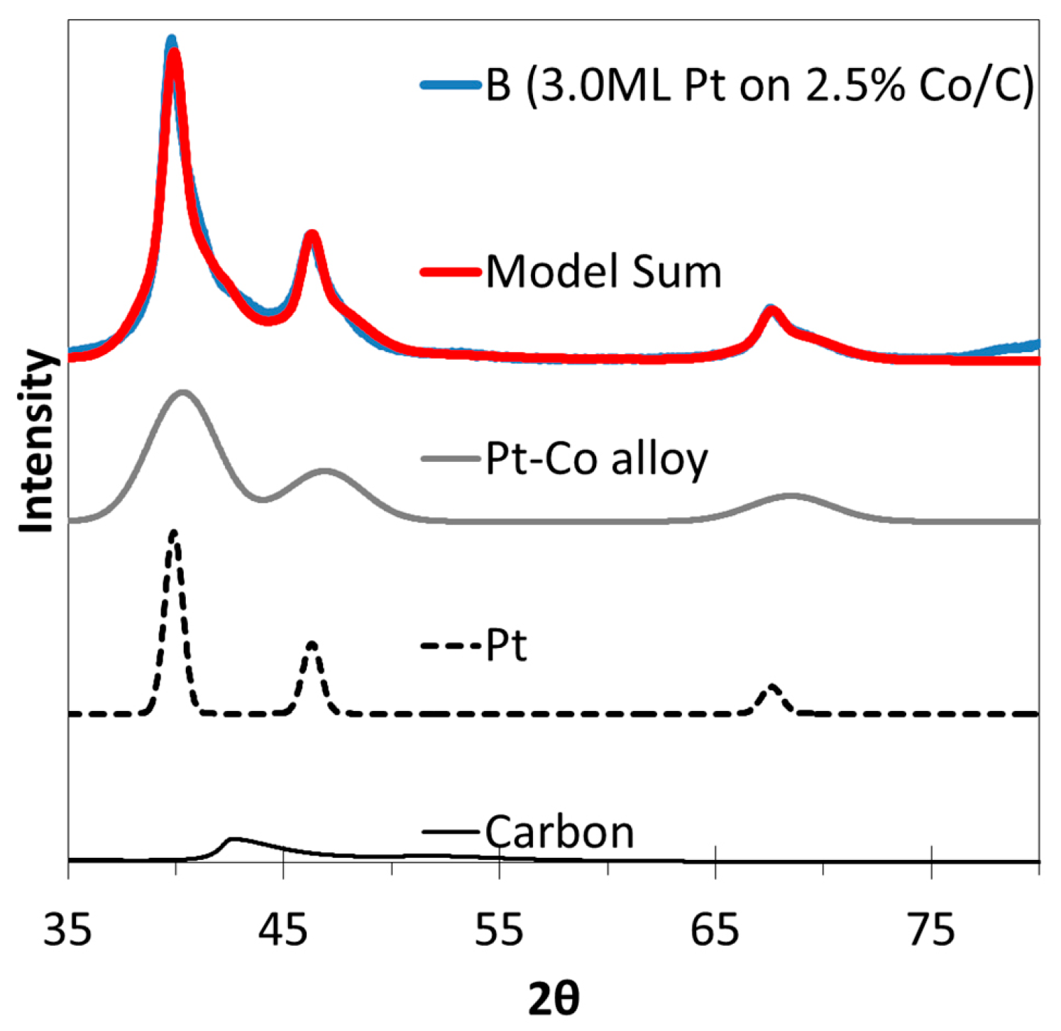
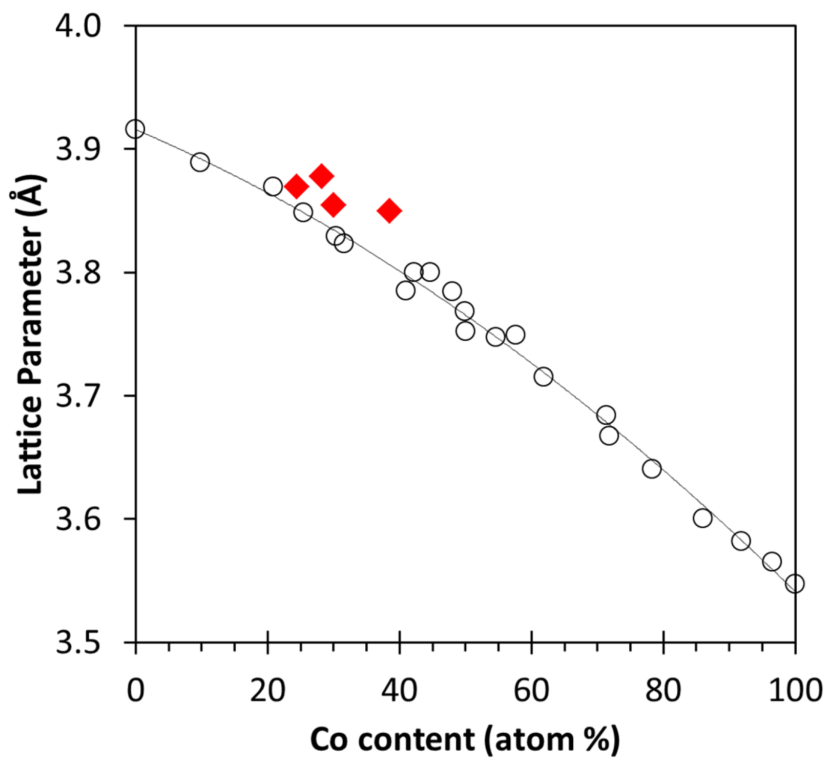
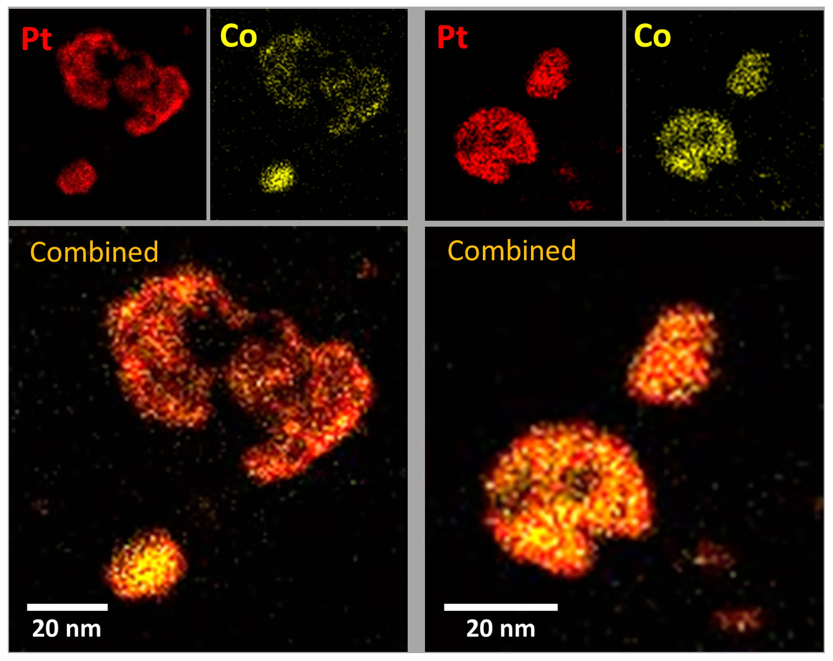
2.3. XRD, HAADF-STEM and XEDS Characterization of Pt-Co/C Catalysts

Powder X-ray diffraction profiles of the Pt-Co catalysts are shown in Figure 6. Prominent diffraction peaks corresponding to face centered cubic (fcc) reflections of Pt° are observed in the XRD patterns of all bimetallic samples. There are also significant shoulders to the right of the Pt peaks suggesting a different fcc phase with a lattice parameter slightly smaller than that of Pt. These shoulder peaks do not correspond to fcc Co0 (PDF card # 01-077-7451). A representative deconvolution profile of one of the XRD patterns is shown in Figure 7. For all of the bimetallic samples the shoulder peaks are noticeably broad indicating that the phases of lower lattice parameter are small structures, about 2.5 nm in size. Using d-spacing calculation for the deconvoluted peaks, the lattice parameters for these shoulders averaged 3.86 Å. From previous studies, this lattice parameter is known to correspond to a Pt-Co alloy fcc phase [38]. The results of the lattice parameter calculations and line broadening size analyses using the Scherrer formula are listed in Table 2.
A prior survey [38] of Pt-Co alloy lattice parameter dependence on metal composition is shown in Figure 8. Data from the current study are also included using the calculated lattice parameter of the Pt-Co alloy observed from XRD and the bulk atomic composition of the metal phases. The lattice parameters of the Pt-Co alloys in this study correspond to a metal composition ranging from 25 to 40 atomic percentage of cobalt by interpolation from the lattice parameter curve.
The formation of alloy phase in the Pt-Co/C samples is not an expected result of the electroless deposition process. Platinum was intended to deposit as a shell over the cobalt seed particles as prior studies have shown for transition metals [17,21,22,23,39], particularly on cobalt [20]. It is possible that the substitution of cobalt into the platinum lattice to form a Pt-Co alloy structure may be due to the simultaneous action of GD with ED, particularly the rapid ED kinetics resulting from the high initial concentration of PtCl62− and the DMAB reducing agent. Further, in addition to the deposition of Pt by ED and GD, the Co2+ in solution can be deposited by ED on the freshly-deposited Pt surface if sufficient DMAB remains in solution, since DMAB is also activated on platinum [40,41]. Thus, we could have simultaneous co-deposition of Pt and Co by ED which might favor formation of Pt-Co alloy structures, since the metallic lattice would form in the presence of both Pt° and Co° atoms. Further, autocatalytic deposition of Pt on Pt likely occurs to form the high Pt content phases calculated from the XRD patterns in Figure 6 and summarized in Table 2. The formation of true alloys in this study by the concurrent action of GD and co-ED of Pt and Co demonstrates a facile method of preparation of alloys without the use of high temperatures typically needed to force alloy lattice structures. Co-electroless deposition will be the subject of future work. In contrast to this work, others [42,43,44,45] have used more complex procedures that include under potential deposition (UPD) and galvanic displacement to produce more conventional Pt-M (M = non-noble transition metal) fuel cell catalysts.
Representative HAADF-STEM images of the samples with the lowest (Sample A) and highest (Sample D) loadings of Pt are shown in Figure 9. Sample D exhibits particles that are mostly large and irregular which can be visually described as hollow shell-like structures having a thickness of about 2.5 nm. Sample A has particles with wide size distribution from 2–20 nm that have a more solid appearance. The structures of Samples B and C (not shown) are intermediate between the range of particle sizes and shapes of the nanoparticles found for Samples A and D, with a mix of both the small compact particles and the large hollow-like structures. The trend of the particle morphology for the Pt-Co/C samples is that higher Pt loadings (see Table 1) have more of the large hollow, shell-like particles. These structures are very likely due to the faster kinetics of electroless deposition, since the ED bath (constant volume bath) contains higher initial amounts of PtCl62− and, more importantly, DMAB, which undergoes rapid catalytic decomposition to release H2 [46,47]. That DMAB is an inefficient reducing agent is well-known and is the reason why a 5-fold molar excess relative to PtCl62− is used during ED. This is also observed visually by the vigorous release of H2 bubbles during the initial stages of deposition. The evolution of H2 likely caused the expansion of the deposited metal shell until rupture occurred.
Energy dispersive X-ray spectroscopy (XEDS) was used to obtain elemental maps, providing information on where the Pt and Co resided in the particles. A representative XEDS micrograph of Sample D is shown in Figure 10, imaging both hollow shell and compact particles. Elemental distribution of the compact particles shows a Pt-rich shell phase and a small Co-rich core on the inside. The hollow shell structure on the other hand shows a more evenly distributed mix of Pt and Co, suggesting the shell is an alloyed Pt-Co phase. The elemental maps corroborate the results of the powder XRD where large domains of Pt-rich phases can be seen from the elemental maps and the exploded shells which are visibly alloyed as seen in XEDS, correspond to the thinner-dimensioned, Pt-Co alloy size estimate from XRD.
The formation of the alloyed hollow shell structures and the core-shell compact particles supports the hypothesis of GD as the mechanism for the loss of Co. The ruptured hollow shells permit access of Co for the GD process, whereas the shell of Pt on the compact particles prevented further Co loss by GD. The alloy formed in the particles with hollow shell morphology further supports the simultaneous GD-ED process for both platinum deposition and cobalt re-deposition and insertion into the alloy lattice.

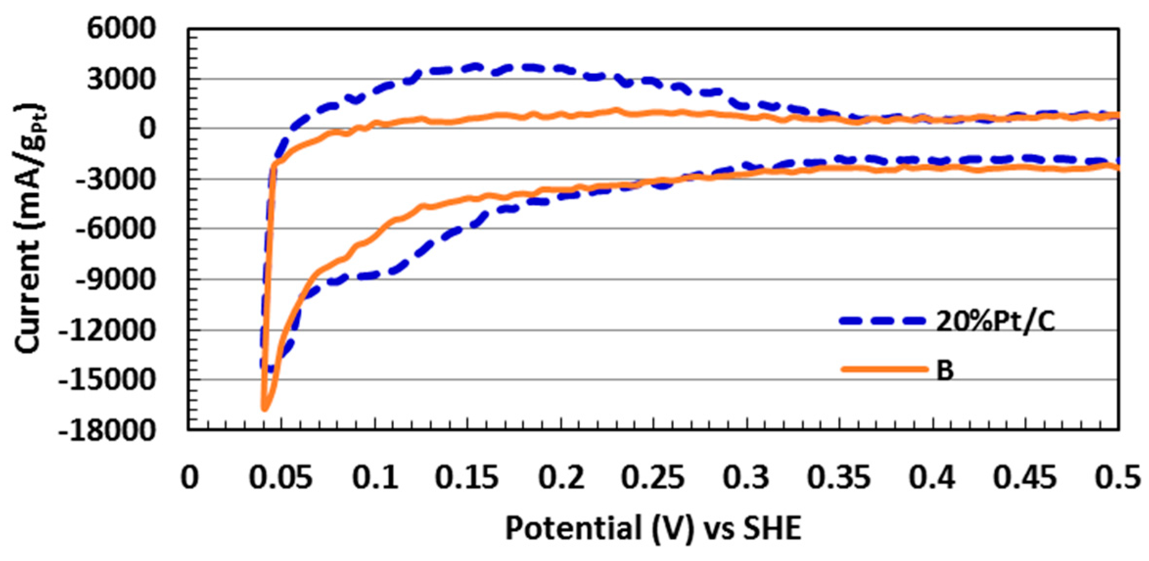
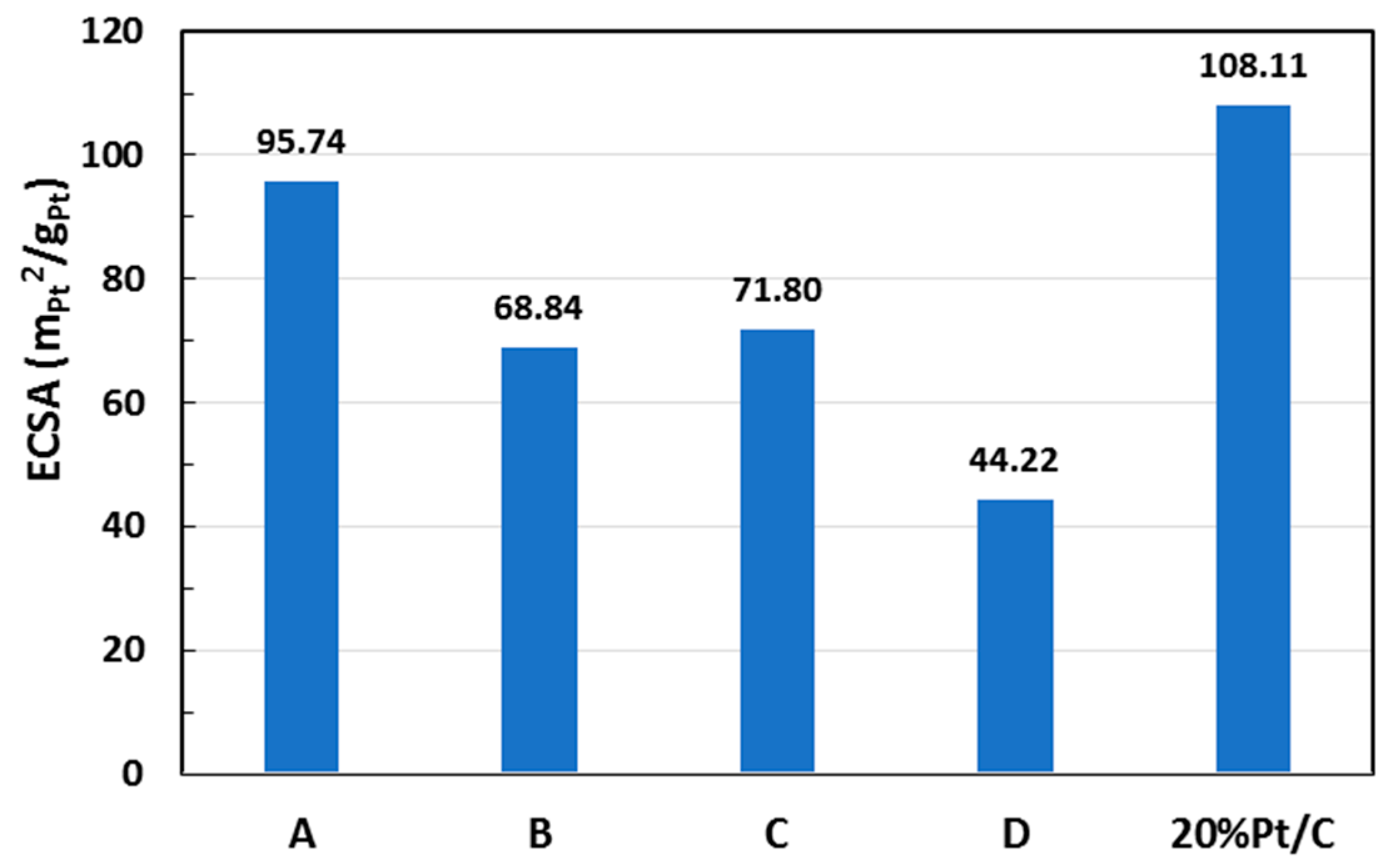
2.4. Catalyst Electrochemical Active Surface Area

Representative cyclic voltammograms of one of the samples (Sample B) and the commercial 20 wt % Pt/C under nitrogen purged electrolyte are shown in Figure 11. The electrochemical surface area (ECSA) was calculated in Equation (2) by measuring the charge density associated with the adsorption of hydrogen (qPt, in µC/m2-electrode) between 0.05 and 0.40 V [48], the charge required to reduce a monolayer of protons on Pt (Γ) which is 210 µC/cm2Pt, and the Pt content or loading on the electrode (L), in gPt/m2-electrode [49].
E C S A ( m 2 Pt g Pt ) = q Pt Γ . L
Comparison of ECSA values for the different catalysts is shown in Figure 12. The ECSA values ranged from 44 to 95 m2Pt/gPt for the different Pt-Co/C catalysts, depending on the catalyst composition and the morphology of the metal nanoparticles. The highest ECSA was recorded for the commercial 20 wt % Pt/C with 108.11 m2Pt/gPt. The ECSA of Sample A (6.7 wt % Pt with 0.9 wt % Co) was only slightly lower at 95.74 m2Pt/gPt. In contrast, Sample D (22.2 wt % Pt with 2.6 wt % Co) exhibited the smallest ECSA value which is attributed to the large Pt particles for this particular sample (Table 2) since large particle sizes have lower surface/volume ratios.

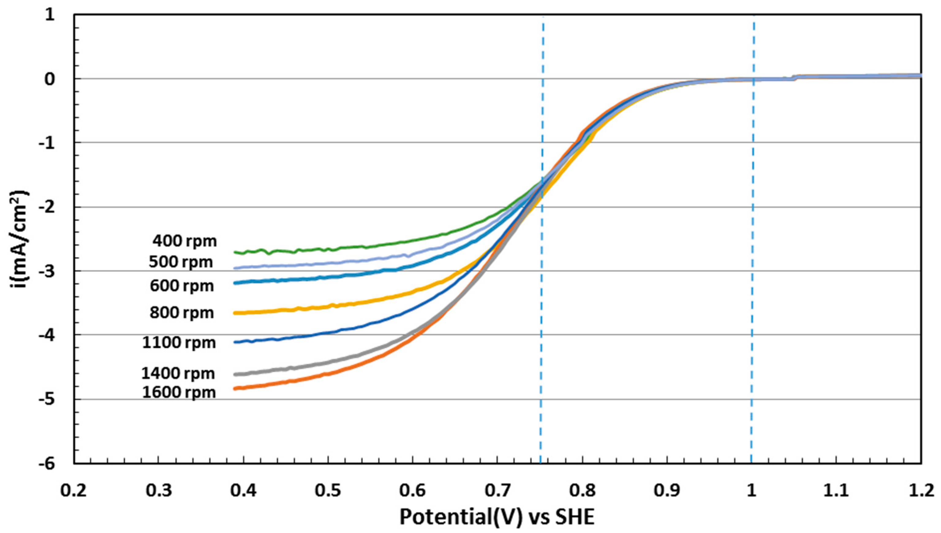
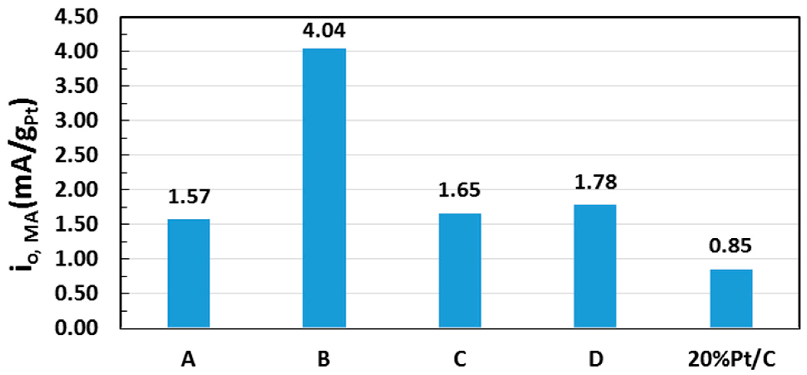
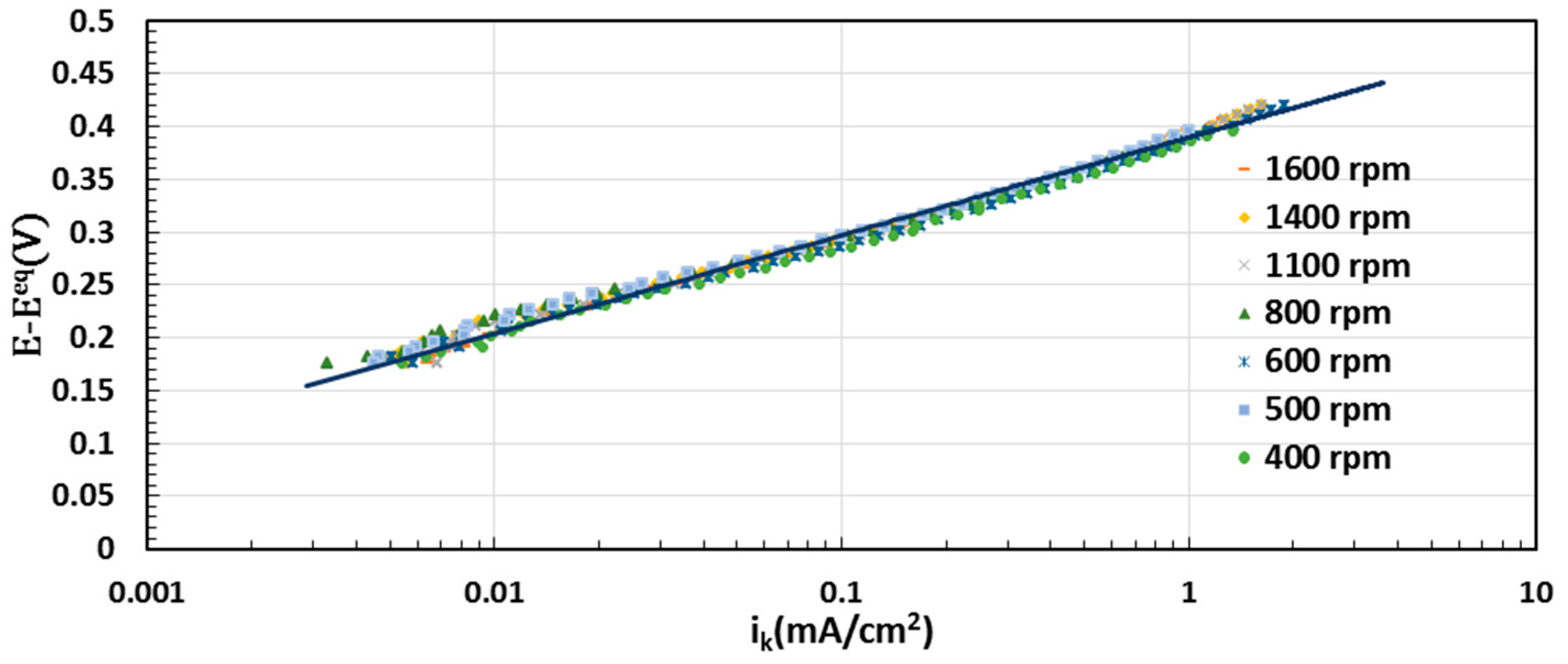
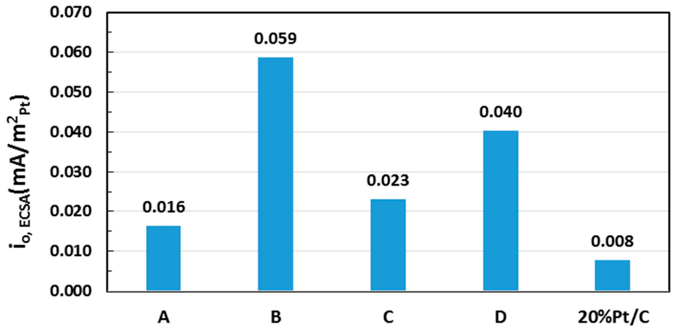
2.5. Electrocatalytic Activity toward ORR

The ORR polarization curves from rotating disk electrode (RDE) were obtained by linear potential sweep at a sweep rate of 5 mV/s and a rotation speed ranging from 350 to 1600 rpm. The responses are corrected by subtraction of background current measured at identical conditions in N2-purged electrolyte without rotation. Figure 13 shows the RDE profiles for Sample B in O2-saturated 0.1 M HClO4. Note that the current was normalized by the geometric surface area of the RDE. All samples exhibited a plateau behavior at low potentials, indicating a diffusion-limited current regime. A mixed kinetic-diffusion region occurred at potentials greater than approximately 0.6 V vs. standard hydrogen electrode (SHE). To remove the effect of diffusion and obtain the purely kinetic current density (ik), the Koutecky-Levich relation was applied [8].
1 i = 1 i k + 1 i D
The analysis used the potential range between 0.75 and 1.0 V vs. SHE as marked in Figure 13 to avoid significant mass-transfer corrections at high currents and excess noise relative to background at low currents. The diffusion limiting current density in Equation (3) (iD) is equal to R(w)0.5, with w as the rotation rate and R is a constant given by the Levich equation [50]. The value for R was obtained by averaging the slope of 1/i vs. 1/w0.5 at all voltages in the potential window indicated above. The resulting R value was used to obtain the kinetic currents at all potentials and rotations rates, which are plotted in Figure 14, with the potential shown relative to the equilibrium potential for oxygen reduction, Eeq = 1.23 V vs. SHE. The overlap of the kinetic current at all rotation speeds indicate the mass transfer effects on the current were eliminated.
Assuming the kinetics can be represented by the Tafel equation given as:
E = E e q + β log ( i 0 ) β log ( i k )
where i0 is the exchange current density and β is the Tafel slope, these two kinetic parameters can be obtained by fitting Equation 4 to the kinetic-current data in Figure 14. The value of β obtained for Pt/C was 66 mV/decade which is the typical value for ORR on platinum material [51]. The Tafel slopes of Pt-Co samples were in the range of 69–78 mV/decade which are in good agreement with other reported values for the Pt-Co/C catalysts [52].
The resulting estimate of i0 is normalized by the geometric area, consistent with the current used in the fit. The Pt mass and Pt active surface area were then used to obtain the exchange current density normalized by either Pt mass (i0, MA) or Pt active area (i0, ECSA).
In order to compare mass activities of different catalysts, the exchange density was normalized to the mass of Pt used. All Pt-Co samples showed higher mass activity (i0, MA) than the commercial Pt/C sample (Figure 15), with Sample B having a mass activity 4.8 times higher than the commercial sample.
Table 3 summarizes the ECSA and the exchange current density normalized by Pt active area (i0, ECSA) of all samples. Additionally, the comparison of i0, ECSA values calculated from the exchange current density are shown in Figure 16. The results show all Pt-Co samples have much higher i0, ECSA than the commercial, Pt-only sample, demonstrating accelerated ORR kinetics on the surfaces of the Pt-Co catalysts. Sample B exhibited a specific activity of 0.0587 mA/m2Pt, 7.5 times greater than the Pt/C catalyst (0.0078 mA/m2Pt).
The results of the current work, where higher platinum mass normalized activities and electrochemical surface activities are observed for the bimetallic ED catalysts, are in line with prior studies [6,7,8,53]. The alloying of Pt with Co enhanced the catalyst properties of Pt that are beneficial for ORR applications; Pt charge density increases either by electronic interaction with Co and/or lattice contraction (strain) by substitution of Co into the Pt lattice. These effects result in the downshift of the Pt d-band which weakens adsorbate binding [10,42,54] to give faster rates of adsorption/desorption of oxygenated species as well as the rate of reduction of surface platinum oxide in the ORR mechanism [8,53].
In summary, electroless deposition of controlled amounts of Pt on Co particles gives much more efficient use of Pt, since the bulk, or core, is composed of a different metal, Co in this study. In addition to ED of Pt on Co, galvanic displacement of Co0 by PtCl62− forms additional Pt0, releasing Co2+ into the ED bath. Once in the bath, co-deposition of both Pt and Co can occur which appears to facilitate the formation of true alloys of Pt and Co. XRD analysis suggests the preferred alloy composition is Pt3Co which has been argued by others to be a superior ORR composition based on structural and electronic factors [6,7,8,53]. If the kinetics of ED are too rapid, particularly, the catalytic activation of the DMAB reducing agent, excessive H2 evolution occurs which can rupture the Pt shell deposited by ED to form an “exploded” hollow shell structure. When activation of DMAB is less aggressive, typical Co core-Pt shell structures are formed.
Evaluation of the electrochemical active surface area (ECSA) of the ED-prepared Pt-Co/C catalysts using cyclic voltammetry indicated the concentration of active surface Pt sites was lower for the ED catalysts, compared to a commercially-available 20 wt % Pt/C catalyst. However, the ECSA for the bimetallic 6.7 wt % Pt–0.9 wt % Co catalyst (Catalyst A) containing the lowest concentration of Pt deposited by ED was only slightly lower than that of the commercial Pt catalyst. The larger Pt particles for the catalysts with higher Pt loadings are likely the cause for the lower ECSA values. However, evaluation for the oxygen reduction reaction (ORR) showed considerably higher mass and surface activities for the ED catalysts compared to the commercial Pt/C sample. This appears to be due to formation of Pt-Co alloy structures for the ED catalysts, consistent with suggestions by others. What is encouraging from this initial study, however, is that much greater control of the ED process, and even carefully-designed co-deposition of both Pt and Co, can be easily implemented to greatly improve performance of the bimetallic Pt-Co system.

3. Materials and Methods

3.1. Carbon Supported Cobalt (Co/C) Base Catalyst

A modified CEDI method [13,14] was employed in the preparation of the base Co/C catalyst for Pt deposition; nominal loadings of 2.5 wt % and 5.0 wt % Co were targeted. Appropriate amounts of cobalt (II) nitrate hexahydrate (Co(NO3)2·6H2O) and an equimolar amount of citric acid were dissolved in a volume of deionized water (DI) water required for pore filling of the carbon support to be impregnated. The pore volume of 3.5 mL/g for the carbon support (Acetylene Black, specific surface area: 320 m2/g, PZC = 3.4, Toyota Motor Engineering & Manufacturing North America, Inc., Ann Arbor, MI, USA) was determined by saturation with deionized water to the state of moistness of the support. The cobalt nitrate–citric acid solution was added dropwise to the carbon with vigorous mixing during addition to give efficient distribution of the precursor liquid in the carbon. The resulting paste was then dried at 25 °C before being crushed into powder.
Temperature programmed decomposition (TPD) of the precursor in flowing He was conducted on a small portion of the dried powder using an Autochem II 2920 Analyzer (Micromeritics, Norcross, GA, USA). Formation of decomposition products was monitored with a thermal conductivity detector (TCD). The peak decomposition temperature was then used for the annealing treatment in flowing He (4 h) for the remainder of the powder. A fraction of the annealed powder was then used for temperature programmed reduction (TPR) analysis in the Autochem II analyzer by using 10% H2/balance Ar (Airgas National Welders, Columbia, SC, USA). Hydrogen consumption was monitored using the TCD. The peak temperature for H2 consumption was set as the reduction temperature (1 h) for the balance of the annealed powder. All annealing and reduction treatments were done in a horizontal tubular furnace and temperature ramp rates for all thermal treatments were set at 5 °C/min. The base Co/C catalyst was then characterized by powder X-ray diffraction (XRD) and high angle annular dark field-scanning transmission electron microscopy (HAADF-STEM) for determination of Co nanoparticle sizes and subsequent calculation of the concentration of cobalt surface sites, assuming spherical Co particles. Details of these characterization techniques are included in the latter part of this section.

3.2. Electroless Deposition of Pt

The electroless developer bath used for the deposition of platinum was based on previous work by Beard et al. [20,21,22], with the modification of substituting citrate for ethylenediamine (EN) as a stabilizing and chelating agent for Pt4+ [23]. For the ED experiments, the aqueous bath was maintained at pH 10 and chloroplatinic acid (H2PtCl6) used as the Pt source (existing as [PtCl6]2− complex in basic solution) and dimethylamine borane ((CH3)2NH·BH3, DMAB) as the reducing agent. Preliminary thermal stability experiments for the bath were conducted to determine a stable formulation of the Pt precursor, reducing agent, and stabilizer, ensuring that PtCl62− did not reduce or precipitate in solution. From the stability experiments, a formulation of Pt:DMAB:EN = 1:5:4 molar ratio, which was stable at 50 °C up to a maximum concentration of PtCl62− = 120 ppm, was used.
After addition of the Co/C base catalyst to the bath, Pt and Co concentrations were determined by Atomic Absorption Spectrometry (AAS, AAnalyst 400, Perkin Elmer, Waltham, MA, USA). Small aliquots of the bath were withdrawn and syringe-filtered at predetermined time intervals and then analyzed. Electroless deposition experiments were conducted for 60 min; a second aliquot of DMAB was added after 30 min. Particulars for the ED experiments are listed in Table 4. The amounts of PtCl62− initially present in the ED bath that correspond to the target coverage based on the calculation of available Co surface sites (from prior XRD characterization). One monolayer (ML) of monodisperse coverage of Pt corresponds to one atom of Pt per one Co surface site.
After each ED experiment, the slurry was filtered and the catalyst powder was washed thoroughly (~2 L) with DI water. Samples were then dried at room temperature before reduction at 200 °C (5 °C/min ramp rate) for 1 h in flowing 25% H2/balance He at 200 SCCM total flow.

3.3. Catalyst Characterization

XRD characterization of the catalysts was done using a Rigaku Miniflex II benchtop diffractometer (Rigaku Americas Corporation, The Woodlands, TX, USA). The diffractometer is equipped with a Cu Kα X-ray source and fitted with a silicon slit detector that is capable of detecting particles in the sub-nanometer size range [55].
Micrographs from HAADF-STEM of the samples were acquired with the cold field emission JEOL JEM-ARM200CF STEM (JEOL USA Inc., Peabody, MA, USA). The JEOL JEM-ARM200CF is probe aberration corrected with a 200 kV beam and the particular microscope used is fitted with JEOL and Gatan detectors for HAADF imaging. Additional imaging of the Pt-Co/C ED particles were carried out using X-ray energy dispersive spectroscopy (XEDS) for elemental mapping of Pt and Co. These maps were generated using an Oxford Instruments X-Max100TLE SDD detector (Oxford Instruments PLC, Abingdon, Oxfordshire, UK), also fitted to the JEM-ARM200CF.

3.4. Electrochemical Evaluation

The electrochemical characteristics of the prepared catalysts were tested in a conventional three-electrode cell system. Cyclic voltammetry (CV) and rotating disk electrode (RDE) tests were performed in 0.1 M HClO4 solution as electrolyte at room temperature. A glassy carbon electrode (GCE) of 5 mm diameter coated with catalyst, a Pt wire, and Ag/AgCl electrode served as working, counter, and reference electrodes, respectively, comprised the electrochemical cell. To form the catalyst ink, 10 mg catalyst was sonicated in a solution of 5.0 mL of DI water and 5.0 mL of isopropyl alcohol. The catalyst/GCE was prepared by casting 18.5 µL of catalyst ink on the glassy carbon surface, and after drying the sample was bound to the working electrode using 3.5 µL of a solution of 5.0 wt % Nafion:IPA (1:20 ratio) [56]. All potentials throughout this paper were referenced to standard hydrogen electrode (SHE). The catalysts were conditioned at 50 mV/s between 0.0 to 1.2 V vs. SHE for 50 cycles and then the CV measurements for determination of the catalyst electrochemical surface area were carried out using three cycles at 5 mV/s between 0.0 to 1.2 V vs. SHE. The CV tests were performed in N2−purged 0.1 M HClO4. Upon completion of the CV measurements, the gas was switched to oxygen to saturate the electrolyte for at least 20 min before ORR activity was subsequently measured. All ORR measurements were performed at a scan rate of 5 mV/s, and the ORR voltammogram was recorded with a rotating disk electrode configuration with rotation speeds varied from 350 to 1600 RPM.

4. Conclusions

A series of carbon-supported Pt-Co bimetallic catalysts were prepared by electroless deposition (ED) of Pt on a Co base catalyst. The preparation of the Co/C catalyst, at loadings of 2.5 wt % and 5.0 wt % Co, used a modified charge enhanced dry impregnation method (CEDI) with citric acid that acted as a chelating agent and support acidifier. This dual effect of the citric acid induced conditions that promoted strong interaction between the anionic cobalt-citrate complex and the positively-charged surface of the carbon. Thermal treatment experiments determined that the cobalt-impregnated carbon could be heated at 250 °C in inert He flow and reduced at 400 °C in dilute H2 flow to yield small particles. X-ray diffraction (XRD) measurements of Co° and cobalt oxide peaks indicated approximately 1.6 nm particles were formed, which was confirmed by high-angle annular dark-field scanning transmission electron microscopy (HAADF-STEM). The Co particle size estimate from XRD was used as a basis for the coverage of Pt during ED experiments.
The electroless developer bath for Pt deposition contained 1:5:4 molar ratios of H2PtCl6, DMAB, and EN as Pt precursor, reducing agent, and stabilizer, respectively. The total amount of H2PtCl6 (actually PtCl62− at the basic, pH 10 conditions of the bath) was used to control the coverage at 1.5 ML and 3.0 ML Pt on both Co/C catalysts. Leaching of Co2+ into the ED bath from galvanic displacement of Co by PtCl62− was observed from inductively coupled plasma (ICP) analysis. Once in the bath co-deposition of both Pt and Co likely occurred which facilitated the formation of true alloys of Pt and Co. Final loadings of Pt ranged from 6.7 wt % to 22.2 wt % while Co was reduced by approximately 50% due to galvanic displacement. XRD analyses confirmed that in addition to Pt°, a Pt-Co alloy phase was indeed formed, and that based on the contracted lattice parameters calculated from the XRD profiles, Pt3Co was the likely composition. Electron micrographs of the samples showed that for the samples with the highest Pt loadings, large particles with thin hollow-shell morphology were formed. If the kinetics of ED were too rapid, especially the catalytic activation of the DMAB reducing agent, excessive H2 evolution occurred which ruptured the Pt shell deposited by ED to form an “exploded” hollow shell structure. When activation of DMAB was less aggressive, typical Co core-Pt shell structures were formed. Finally, XEDS mapping determined that the thin hollow-shells were comprised of a Pt-Co alloy phase while the smaller compact particles consisted of Co-rich cores and thicker Pt-rich shells.
Evaluation of the electrochemical active surface area (ECSA) of the ED-prepared Pt-Co/C catalysts using cyclic voltammetry indicated the concentration of active surface Pt sites was lower for the ED catalysts, compared to a commercially-available 20 wt % Pt/C catalyst. However, the ECSA for the bimetallic 6.7 wt % Pt–0.9 wt % Co catalyst (Catalyst A) containing the lowest concentration of Pt deposited by ED was only slightly lower than that of the commercial Pt catalyst. The larger Pt particles for the catalysts with higher Pt loadings are likely the cause for the lower ECSA values. However, evaluation for the oxygen reduction reaction (ORR) showed considerably higher mass and surface activities for the ED catalysts compared to the commercial Pt/C sample. This appears to be due to formation of Pt-Co alloy structures for the ED catalysts, consistent with suggestions by others.
This study has shown the viability of ED and CEDI methods for the production of carbon-supported bimetallic Pt-Co particles that have higher activity than current commercially available monometallic catalysts for ORR. Results from this initial study also suggest that with greater control of the ED process kinetics, and possibly co-deposition of both Pt and Co, greatly improved performance of the bimetallic Pt-Co system may be attained.
Further works on the fine tuning of the bath conditions to achieve slower deposition rates and yielding better dispersed bimetallic particles are to be the subject of another study.

Acknowledgments

The authors would like to thank the Alan Nicholls and the Electron Microscopy Service of the University of Illinois at Chicago for the STEM and XEDS imaging. The authors gratefully acknowledge partial financial support from NSF I/UCRC No. 1464630 and NSF CBET No. 1160036 while this work was being done.

Author Contributions

Conception and design of the experiments were done with guidance of J.R.M., J.R.R., and J.W.W. as principal investigators; experiments were performed by J.M.M.T., Y.Z., A.W., and B.A.T.M.; J.M.M.T. wrote the paper with contribution by B.A.T.M. for electrochemical experiments; all authors participated in the analysis, interpretation, and review of the results and provided input in the writing process of the paper.

Conflicts of Interest

The funding sponsors had no role in the design of the study; in the collection, analyses, or interpretation of data; in the writing of the manuscript, and in the decision to publish the results.

References

  1. Redmond, E.L.; Setzler, B.P.; Juhas, P.; Billinge, S.J.L.; Fuller, T.F. In-Situ Monitoring of Particle Growth at PEMFC Cathode under Accelerated Cycling Conditions. Electrochem. Solid State Lett. 2012, 15, B72–B74. [Google Scholar] [CrossRef]
  2. Takeuchi, N.; Fuller, T.F. Modeling and Investigation of Carbon Loss on the Cathode Electrode during PEMFC Operation. J. Electrochem. Soc. 2010, 157, B135–B140. [Google Scholar] [CrossRef]
  3. Kinoshita, K. Particle Size Effects for Oxygen Reduction on Highly Dispersed Platinum in Acid Electrolytes. J. Electrochem. Soc. 1990, 137, 845–848. [Google Scholar] [CrossRef]
  4. Kabbabi, A.; Gloaguen, F.; Andolfatto, F.; Durand, R. Particle size effect for oxygen reduction and methanol oxidation on Pt/C inside a proton exchange membrane. J. Electroanal. Chem. 1994, 373, 251–254. [Google Scholar] [CrossRef]
  5. Wikander, K.; Ekström, H.; Palmqvist, A.E.C.; Lindbergh, G. On the influence of Pt particle size on the PEMFC cathode performance. Electrochim. Acta 2007, 52, 6848–6855. [Google Scholar] [CrossRef]
  6. Nikkuni, F.R.; Dubau, L.; Ticianelli, E.A.; Chatenet, M. Accelerated degradation of Pt3Co/C and Pt/C electrocatalysts studied by identical-location transmission electron microscopy in polymer electrolyte environment. Appl. Catal. B Environ. 2015, 176–177, 486–499. [Google Scholar] [CrossRef]
  7. Xu, Q.; Kreidler, E.; He, T. Performance and durability of PtCo alloy catalysts for oxygen electroreduction in acidic environments. Electrochim. Acta 2010, 55, 7551–7557. [Google Scholar] [CrossRef]
  8. Wang, D.L.; Xin, H.L.L.; Hovden, R.; Wang, H.S.; Yu, Y.C.; Muller, D.A.; DiSalvo, F.J.; Abruna, H.D. Structurally ordered intermetallic platinum-cobalt core-shell nanoparticles with enhanced activity and stability as oxygen reduction electrocatalysts. Nat. Mater. 2013, 12, 81–87. [Google Scholar] [CrossRef] [PubMed]
  9. Habibi, B.; Ghaderi, S. Synthesis, characterization and electrocatalytic activity of Co@Pt nanoparticles supported on carbon-ceramic substrate for fuel cell applications. Int. J. Hydrog. Energy 2015, 40, 5115–5125. [Google Scholar] [CrossRef]
  10. Xin, H.; Holewinski, A.; Linic, S. Predictive Structure-Reactivity Models for Rapid Screening of Pt-Based Multimetallic Electrocatalysts for the Oxygen Reduction Reaction. ACS Catal. 2012, 2, 12–16. [Google Scholar] [CrossRef]
  11. Ferrin, P.; Nilekar, A.U.; Greeley, J.; Mavrikakis, M.; Rossmeisl, J. Reactivity descriptors for direct methanol fuel cell anode catalysts. Surf. Sci. 2008, 602, 3424–3431. [Google Scholar] [CrossRef]
  12. Herron, J.A.; Mavrikakis, M. On the composition of bimetallic near-surface alloys in the presence of oxygen and carbon monoxide. Catal. Commun. 2014, 52, 65–71. [Google Scholar] [CrossRef]
  13. Cao, C.; Yang, G.; Dubau, L.; Maillard, F.; Lambert, S.D.; Pirard, J.-P.; Job, N. Highly dispersed Pt/C catalysts prepared by the Charge Enhanced Dry Impregnation method. Appl. Catal. B Environ. 2014, 150–151, 101–106. [Google Scholar] [CrossRef]
  14. Zhu, X.; Cho, H.-R.; Pasupong, M.; Regalbuto, J.R. Charge-Enhanced Dry Impregnation: A Simple Way to Improve the Preparation of Supported Metal Catalysts. ACS Catal. 2013, 3, 625–630. [Google Scholar] [CrossRef]
  15. Regalbuto, J.R. Strong Electrostatic Adsorption of Metals onto Catalyst Supports. In Catalyst Preparation: Science and Engineering; Regalbuto, J.R., Ed.; Taylor and Francis/CRC Press: Boca Raton, FL, USA, 2007; pp. 297–318. [Google Scholar]
  16. Rodriguez, A.A.; Williams, C.T.; Monnier, J.R. Selective liquid-phase oxidation of glycerol over Au-Pd/C bimetallic catalysts prepared by electroless deposition. Appl. Catal. A Gen. 2014, 475, 161–168. [Google Scholar] [CrossRef]
  17. Diao, W.; Tengco, J.M.M.; Regalbuto, J.R.; Monnier, J.R. Preparation and Characterization of Pt-Ru Bimetallic Catalysts Synthesized by Electroless Deposition Methods. ACS Catal. 2015, 5, 5123–5134. [Google Scholar] [CrossRef]
  18. Zhang, Y.; Diao, W.; Williams, C.T.; Monnier, J.R. Selective hydrogenation of acetylene in excess ethylene using Ag- and Au-Pd/SiO2 bimetallic catalysts prepared by electroless deposition. Appl. Catal. A Gen. 2014, 469, 419–426. [Google Scholar] [CrossRef]
  19. Schaal, M.T.; Pickerell, A.C.; Williams, C.T.; Monnier, J.R. Characterization and evaluation of Ag-Pt/SiO2 catalysts prepared by electroless deposition. J. Catal. 2008, 254, 131–143. [Google Scholar] [CrossRef]
  20. Beard, K.D.; Borrelli, D.; Cramer, A.M.; Blom, D.; van Zee, J.W.; Monnier, J.R. Preparation and Structural Analysis of Carbon-Supported Co Core/Pt Shell Electrocatalysts Using Electroless Deposition Methods. ACS Nano 2009, 3, 2841–2853. [Google Scholar] [CrossRef] [PubMed]
  21. Beard, K.D.; Schaal, M.T.; van Zee, J.W.; Monnier, J.R. Preparation of highly dispersed PEM fuel cell catalysts using electroless deposition methods. Appl. Catal. B Environ. 2007, 72, 262–271. [Google Scholar] [CrossRef]
  22. Beard, K.D.; van Zee, J.W.; Monnier, J.R. Preparation of carbon-supported Pt-Pd electrocatalysts with improved physical properties using electroless deposition methods. Appl. Catal. B Environ. 2009, 88, 185–193. [Google Scholar] [CrossRef]
  23. Wongkaew, A.; Zhang, Y.; Tengco, J.M.M.; Blom, D.A.; Sivasubramanian, P.; Fanson, P.T.; Regalbuto, J.R.; Monnier, J.R. Characterization and evaluation of Pt-Pd electrocatalysts prepared by electroless deposition. Appl. Catal. B Environ. 2016, 188, 367–375. [Google Scholar] [CrossRef]
  24. Garrick, T.R.; Diao, W.; Tengco, J.M.; Stach, E.A.; Senanayake, S.D.; Chen, D.A.; Monnier, J.R.; Weidner, J.W. The Effect of the Surface Composition of Ru-Pt Bimetallic Catalysts for Methanol Oxidation. Electrochim. Acta 2016, 195, 106–111. [Google Scholar] [CrossRef]
  25. Bezemer, G.L.; Radstake, P.B.; Koot, V.; van Dillen, A.J.; Geus, J.W.; de Jong, K.P. Preparation of Fischer-Tropsch cobalt catalysts supported on carbon nanofibers and silica using homogeneous deposition-precipitation. J. Catal. 2006, 237, 291–302. [Google Scholar] [CrossRef]
  26. Yang, Y.; Jia, L.; Meng, Y.; Hou, B.; Li, D.; Sun, Y. Fischer-Tropsch Synthesis over Ordered Mesoporous Carbon Supported Cobalt Catalysts: The Role of Amount of Carbon Precursor in Catalytic Performance. Catal. Lett. 2011, 142, 195–204. [Google Scholar] [CrossRef]
  27. Lu, J.; Huang, C.; Bai, S.; Jiang, Y.; Li, Z. Thermal decomposition and cobalt species transformation of carbon nanotubes supported cobalt catalyst for Fischer-Tropsch synthesis. J. Nat. Gas Chem. 2012, 21, 37–42. [Google Scholar] [CrossRef]
  28. Bychko, I.; Kalishyn, Y.; Strizhak, P. TPR Study of Core-Shell Fe@Fe3O4 Nanoparticles Supported on Activated Carbon and Carbon Nanotubes. Adv. Mater. Phys. Chem. 2012, 2, 17–22. [Google Scholar] [CrossRef]
  29. Reuel, R.C.; Bartholomew, C.H. The stoichiometries of H2 and CO adsorptions on cobalt: Effects of support and preparation. J. Catal. 1984, 85, 63–77. [Google Scholar] [CrossRef]
  30. Bergwerff, J.A.; Lysova, A.A.; Espinosa-Alonso, L.; Koptyug, I.V.; Weckhuysen, B.M. Monitoring Transport Phenomena of Paramagnetic Metal-Ion Complexes Inside Catalyst Bodies with Magnetic Resonance Imaging. Chem. A Eur. J. 2008, 14, 2363–2374. [Google Scholar] [CrossRef] [PubMed]
  31. Mochizuki, T.; Hara, T.; Koizumi, N.; Yamada, M. Novel preparation method of highly active Co/SiO2 catalyst for Fischer-Tropsch synthesis with chelating agents. Catal. Lett. 2007, 113, 165–169. [Google Scholar] [CrossRef]
  32. Miulović Snežana, M.; Nikolić Vladimir, M.; Laušević Petar, Z.; Aćimović Danka, D.; Tasić Gvozden, S.; Marčeta-Kaninski Milica, P. Electrochemistry of cobalt ethylenediamine complexes at high pH. J. Serbian Chem. Soc. 2015, 80, 1515–1527. [Google Scholar] [CrossRef]
  33. Lee, C.-L.; Tseng, C.-M. Ag-Pt Nanoplates: Galvanic Displacement Preparation and Their Applications As Electrocatalysts. J. Phys. Chem. C 2008, 112, 13342–13345. [Google Scholar] [CrossRef]
  34. Lee, C.-L.; Tseng, C.-M.; Wu, R.-B.; Wu, C.-C.; Syu, S.-C. Catalytic characterization of hollow silver/palladium nanoparticles synthesized by a displacement reaction. Electrochim. Acta 2009, 54, 5544–5547. [Google Scholar] [CrossRef]
  35. Micheaud, C.; Marécot, P.; Guérin, M.; Barbier, J. Preparation of alumina supported palladium-platinum catalysts by surface redox reactions. Activity for complete hydrocarbon oxidation. Appl. Catal. A Gen. 1998, 171, 229–239. [Google Scholar] [CrossRef]
  36. Podlovchenko, B.I.; Zhumaev, U.E.; Maksimov, Y.M. Galvanic displacement of copper adatoms on platinum in solutions. J. Electroanal. Chem. 2011, 651, 30–37. [Google Scholar] [CrossRef]
  37. Bard, A.J.; Faulkner, L.R. Electrochemical Methods: Fundamentals and Applications; Wiley: Hoboken, NJ, USA, 2000. [Google Scholar]
  38. Darling, A.S. Cobalt-platinum alloys. Platin. Met. Rev. 1963, 7, 96–104. [Google Scholar]
  39. Ohashi, M.; Beard, K.D.; Ma, S.; Blom, D.A.; St-Pierre, J.; van Zee, J.W.; Monnier, J.R. Electrochemical and structural characterization of carbon-supported Pt-Pd bimetallic electrocatalysts prepared by electroless deposition. Electrochim. Acta 2010, 55, 7376–7384. [Google Scholar] [CrossRef]
  40. Ohno, I. Electrochemistry of electroless plating. Mater. Sci. Eng. A 1991, 146, 33–49. [Google Scholar] [CrossRef]
  41. Ohno, I.; Wakabayashi, O.; Haruyama, S. Anodic Oxidation of Reductants in Electroless Plating. J. Electrochem. Soc. 1985, 132, 2323–2330. [Google Scholar] [CrossRef]
  42. Zhang, Y.; Ma, C.; Zhu, Y.; Si, R.; Cai, Y.; Wang, J.X.; Adzic, R.R. Hollow core supported Pt monolayer catalysts for oxygen reduction. Catal. Today 2013, 202, 50–54. [Google Scholar] [CrossRef]
  43. Zhou, W.-P.; Vukmirovic, M.; Sasaki, K.; Adzic, R. Oxygen Reduction Reaction on a Pt Monolayer on Pd2Co(111) Crystals. Meet. Abstr. 2008, 13, 23–28. [Google Scholar]
  44. Tegou, A.; Papadimitriou, S.; Mintsouli, I.; Armyanov, S.; Valova, E.; Kokkinidis, G.; Sotiropoulos, S. Rotating disc electrode studies of borohydride oxidation at Pt and bimetallic Pt-Ni and Pt-Co electrodes. Catal. Today 2011, 170, 126–133. [Google Scholar] [CrossRef]
  45. Papadimitriou, S.; Armyanov, S.; Valova, E.; Hubin, A.; Steenhaut, O.; Pavlidou, E.; Kokkinidis, G.; Sotiropoulos, S. Methanol Oxidation at Pt-Cu, Pt-Ni, and Pt-Co Electrode Coatings Prepared by a Galvanic Replacement Process. J. Phys. Chem. C 2010, 114, 5217–5223. [Google Scholar] [CrossRef]
  46. Djokić, S.S. Electroless Deposition of Metals and Alloys. In Modern Aspects of Electrochemistry; Conway, B.E., White, R.E., Eds.; Springer: Boston, MA, USA, 2002; pp. 51–133. [Google Scholar]
  47. Haruyama, S.; Ohno, I. Catalytic Aspects in Electroless Deposition; Paunovic, M., Ohno, I., Eds.; Electrochemical Society: Pennington, NJ, USA, 1988; pp. 20–36. [Google Scholar]
  48. Cooper, K.R. In Situ PEM Fuel Cell Electrochemical Surface Area and Catalyst Utilization Measurement. Fuel Cell Mag. 2009, 9. [Google Scholar]
  49. Huang, H.; Sun, D.; Wang, X. PtCo alloy nanoparticles supported on graphene nanosheets with high performance for methanol oxidation. Chin. Sci. Bull. 2012, 57, 3071–3079. [Google Scholar] [CrossRef]
  50. Jiang, R.; Tran, D.T.; McClure, J.P.; Chu, D. Increasing the electrochemically available active sites for heat-treated hemin catalysts supported on carbon black. Electrochim. Acta 2012, 75, 185–190. [Google Scholar] [CrossRef]
  51. Dong, Q.; Santhanagopalan, S.; White, R.E. Simulation of the Oxygen Reduction Reaction at an RDE in 0.5 M H2SO4 Including an Adsorption Mechanism. J. Electrochem. Soc. 2007, 154, A888–A899. [Google Scholar] [CrossRef]
  52. Paulus, U.A.; Wokaun, A.; Scherer, G.G.; Schmidt, T.J.; Stamenkovic, V.; Radmilovic, V.; Markovic, N.M.; Ross, P.N. Oxygen Reduction on Carbon-Supported Pt-Ni and Pt-Co Alloy Catalysts. J. Phys. Chem. B 2002, 106, 4181–4191. [Google Scholar] [CrossRef]
  53. Ishiguro, N.; Saida, T.; Uruga, T.; Nagamatsu, S.-I.; Sekizawa, O.; Nitta, K.; Yamamoto, T.; Ohkoshi, S.-I.; Iwasawa, Y.; Yokoyama, T.; et al. Operando Time-Resolved X-ray Absorption Fine Structure Study for Surface Events on a Pt3Co/C Cathode Catalyst in a Polymer Electrolyte Fuel Cell during Voltage-Operating Processes. ACS Catal. 2012, 2, 1319–1330. [Google Scholar] [CrossRef]
  54. Zhang, J.; Lima, F.H.B.; Shao, M.H.; Sasaki, K.; Wang, J.X.; Hanson, J.; Adzic, R.R. Platinum Monolayer on Nonnoble Metal-Noble Metal Core-Shell Nanoparticle Electrocatalysts for O2 Reduction. J. Phys. Chem. B 2005, 109, 22701–22704. [Google Scholar] [CrossRef] [PubMed]
  55. O’Connell, K.; Regalbuto, J.R. High Sensitivity Silicon Slit Detectors for 1 nm Powder XRD Size Detection Limit. Catal. Lett. 2015, 145, 777–783. [Google Scholar] [CrossRef]
  56. Fuentes, R.E.; García, B.L.; Weidner, J.W. Effect of Titanium Dioxide Supports on the Activity of Pt-Ru toward Electrochemical Oxidation of Methanol. J. Electrochem. Soc. 2011, 158, B461–B466. [Google Scholar] [CrossRef]
Figure 1. Temperature programmed decomposition (TPD) of carbon impregnated with Co(NO3)2 and citric acid.
Catalysts 06 00083 g001
Figure 2. Temperature programmed reduction (TPR) profile in 10% H2/Ar of annealed Co/C sample.
Catalysts 06 00083 g002
Figure 3. Powder X-ray diffraction (XRD) profiles of the reduced 5.0 wt % and 2.5 wt % Co/C samples showing the positions of the most prominent cobalt and cobalt oxide peaks.
Catalysts 06 00083 g003
Figure 4. Representative micrograph from high-angle annular dark-field scanning transmission electron microscopy (HAADF-STEM) of the 5.0 wt % Co/C sample with the cobalt particles appearing as brighter spots compared to the carbon support that appears as a gray background.
Catalysts 06 00083 g004
Figure 5. Stability test and electroless deposition (ED) profiles for electroless developer bath platinum concentration. ED bath maintained at pH 10 during the 60 min deposition period.
Catalysts 06 00083 g005
Figure 6. Powder X-ray diffraction profiles of Pt-Co/C series of samples. Peak positions of pure platinum phase are shown by black diamonds at the appropriate 2θ values.
Catalysts 06 00083 g006
Figure 7. A representative illustration of the deconvoluted profiles of Pt and Pt-Co alloy phases in Sample B (3.0 ML—monolayer) Pt on 2.5 wt % Co/C).
Catalysts 06 00083 g007
Figure 8. Lattice parameter curve for Pt-Co alloy phases indicating results from prior studies (circles) and current work (red diamonds).
Catalysts 06 00083 g008
Figure 9. Representative micrographs from HAADF-STEM of ED Samples A (left) and D (right).
Catalysts 06 00083 g009
Figure 10. Representative X-ray energy dispersive spectroscopy elemental maps of Pt and Co for Sample D (22.2 wt % Pt with 2.6 wt % Co).
Catalysts 06 00083 g010
Figure 11. Comparison of cyclic voltammetry (CV) at 5.0 mV/s in N2 saturated 0.1 M HClO4.
Catalysts 06 00083 g011
Figure 12. Electrochemical active surface area (ECSA) for 5.0 mV/s in N2 saturated 0.1 M HClO4.
Catalysts 06 00083 g012
Figure 13. Current-potential curves at different electrode rotating rates, recorded on a glassy carbon electrode using a potential scan rate of 5.0 mV/s.
Catalysts 06 00083 g013
Figure 14. Examples of Tafel plots for oxygen reduction reaction (ORR) on sample B at different rotation speeds. The line shows the fit of Equation (4) to the data.
Catalysts 06 00083 g014
Figure 15. Mass activities (mA/gPt) of the different catalysts.
Catalysts 06 00083 g015
Figure 16. Specific activity (mA/m2Pt) of different catalysts.
Catalysts 06 00083 g016
Table 1. Compositions of the electroless deposition (ED) prepared Pt-Co/C sample series.
CatalystPt Coverage θPt (Theoretical)Co Loading before ED wt % (Nominal)Final Pt LoadingFinal Co Loading
wt %Atomic% (Metal Basis)wt %Atomic% (Metal Basis)
A1.52.56.770.10.929.9
B3.02.512.275.61.224.4
C1.55.012.661.52.438.5
D3.05.022.271.92.628.1
Table 2. Results of calculation of the Pt and Pt-Co phase sizes from deconvolution of X-ray line broadening profiles.
CatalystTheoretical Monodisperse Coverage of Pt (ML—monolayer)Initial Co Loading (wt %)XRD Sizes
Alloy (Pt-Co) PhaseNon-Alloyed Pt Size (nm)
Lattice Parameter (Å)Size (nm)
A1.52.53.852.611.8
B3.02.53.872.38.9
C1.55.03.852.311.0
D3.05.03.882.310.6
Table 3. Summary of the ECSA and exchange current density values normalized by Pt active area (i0, ECSA) of different catalysts.
SamplePt (% Loading)ECSA (m2/gPt)i0, ECSA (mA/m2Pt)
A6.7195.70.016
B12.268.80.059
C12.671.80.023
D22.244.20.040
20 wt % Pt/C *20.0108.10.008
* nominal.
Table 4. Electroless deposition experiment parameters.
CatalystTarget Pt Coverage (ML)Total Co/C Amount Used (g)Total Bath Volume (mL)
2.5% Co/CB11.51.0600
3.00.5600
5.0% Co/CB11.51.01200
3.00.51200

