Article

Positive Effect of Heat Treatment on Carbon-Supported CoS Nanocatalysts for Oxygen Reduction Reaction

State Key Laboratory of Chemical Resource Engineering, Beijing University of Chemical Technology, 15 Beisanhuan Eastroad, Beijing 100029, China
*
Author to whom correspondence should be addressed.
Catalysts 2015, 5(3), 1211-1220; https://doi.org/10.3390/catal5031211
Submission received: 7 May 2015 / Revised: 25 June 2015 / Accepted: 29 June 2015 / Published: 15 July 2015
(This article belongs to the Special Issue Electrocatalysis in Fuel Cells)

Abstract

:
It is of increasing interest and an important challenge to develop highly efficient less-expensive cathode catalysts for anion-exchange membrane fuel cells (AEMFCs). In this work, we have directly prepared a carbon-supported CoS nanocatalyst in a solvothermal route and investigated the effect of heat-treatment on electrocatalytic activity and long-term stability using rotating ring-disk electrode (RRDE). The results show that the heat-treatment below 400 °C under nitrogen atmosphere significantly enhanced the electrocatalytic performance of CoS catalyst as a function of annealed temperature in terms of the cathodic current density, the half-wave potential, the HO2 product and the number of electrons transferred. The CoS catalyst that annealed at 400 °C (CoS-400) has exhibited a promising performance with the half-wave potential of 0.71 V vs. RHE (the highest one for non-precious metal chalcogenides), the minimum HO2 product of 4.3% at 0.60 V vs. RHE and close to the 4-electron pathway during the oxygen reduction reaction in 0.1 M KOH. Also, the CoS-400 catalyst has comparable durability to the Pt/C catalyst.

1. Introduction

The polymer electrolyte membrane fuel cells system is one of the best alternative candidates to fossil power systems because of high power density, high efficiency and near zero emission [1,2,3]. Compared with proton-exchange membrane fuel cells (PEMFCs), anion-exchange membrane fuel cells (AEMFCs) are attracting more interest because cathode electrocatalysts have higher oxygen reduction kinetics, longer durability and more choices among non-Pt metals in alkaline media [4]. However, it still remains a big challenge and it is of great interest to develop highly efficient less-expensive electrocatalysts for oxygen reduction reaction (ORR) in alkaline media [5,6,7,8].
Recently, non-precious metal chalcogenides, e.g., MS2 {M = Fe [9], Co and (Co, Ni) [10]} thin film, CoS2 [11], CoSe2 [12,13], Co1−xS [14] nanoparticles have attracted extensive attention due to promising catalytic activity for ORR, low cost and abundant reserve in the earth’s crust. In Ref. [13,14], one notes that heat treatment plays an important role to produce electrocatalysts with high performance. However, Dai and his coauthors did not explain the reason for annealing treatment in Ref. [14]. As reviewed by Zhang et al. [15], heat treatment can significantly affect the ORR catalytic activity and stability of the supported catalysts. However, few researchers have focused on the effect of heat treatment on the ORR electrocatalytic performance of non-precious metal chalcogenides [16,17].
In this work, we directly prepared the carbon-supported CoS nanocatalyst as one of the non-precious metal cathodic catalysts in a solvothermal route and specially investigated the effect of heat-treatment temperature on electrocatalytic performance of the prepared nanocatalysts towards ORR in alkaline medium.

2. Results and Discussion

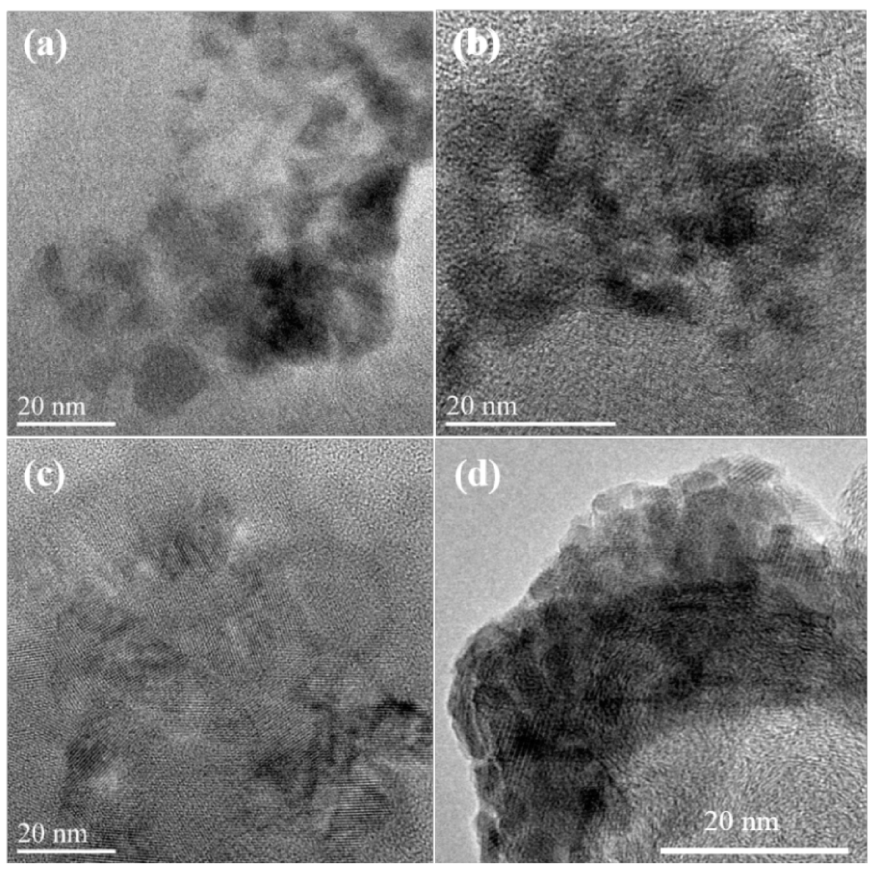
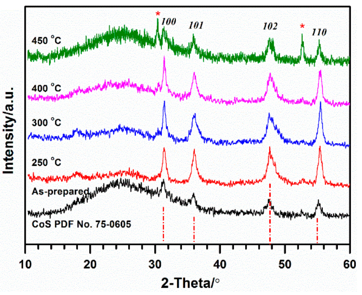
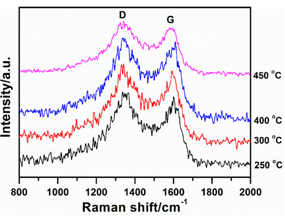
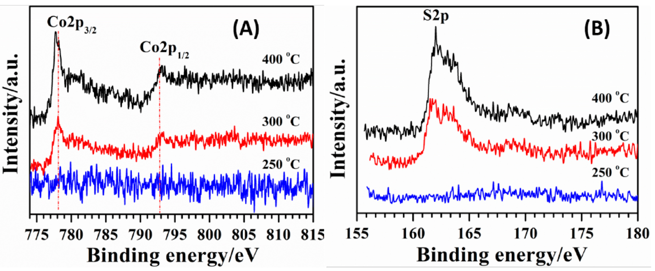
2.1. Structure and Morphology

Figure 1 shows powder X-ray diffraction (XRD) patterns of five prepared 20 wt. % CoS/C samples: those that were as-prepared and those that were annealed at 250, 300, 400 and 450 °C under nitrogen atmosphere, respectively. Compared with the ICDD-PDF2-2004 card of CoS No. 75-0605 in space group P63/mmc (No. 194), the first four samples exhibit four characteristic Bragg reflection peaks of CoS phase, i.e., (100), (101), (102) and (110) as marked in the graph while CoS-450 reveals reflections from another phase as denoted with an asterisk besides CoS phase. After careful comparison and analysis, the impurity is possibly attributed to Co9S8 (PDF No. 86-2273) with two typical characterization peaks (2θ) located at 29.84°/311 and 53.10°/440. Furthermore, the corresponding crystallite size was evaluated based on the Scherrer equation: Dhkl = Kλ/β∙cosθ, where Dhkl, K, λ, β and θ are the crystallite size in the hkl direction (nm), the shape factor (K = 1.0), the X-ray wavelength (λ = 0.15406 nm), the full-width at half maximum (rad) and the Bragg reflection angle (°), respectively. Based on (100), (101) and (102) Bragg reflection peaks, the average crystallite size was individually 6.6 nm, 8.5 nm, 10.1 nm, 11.6 nm and 12.7 nm for the five samples with an increase in the annealed temperature. These results suggest that this mild synthesis route is available for CoS nanoparticles when the S/Co molar ratio in the initial reaction solution is equal to 3.0. Furthermore, the thermal stability of the prepared CoS nanoparticles is below 450 °C, which is similar to that of CoSe2 nanoparticles [13], and lower than that of Co1−xS [14]. In this work, therefore, our following investigation will mainly concentrate on four samples: as-prepared, CoS-250, -300 and -400.
Figure 1. Powder X-ray diffraction patterns of the as-prepared 20 wt. % CoS/C sample and four annealed samples at four different temperatures: CoS-250, -300, -400 and -450, respectively. Vertical dot-dashed lines represent the ICDD-PDF2-2004 card of CoS No.75-0605.
Catalysts 05 01211 g001
In order to further investigate the influence of CoS nanoparticles on carbon substrate during the annealed process, the Raman spectra of the prepared CoS/C at different temperatures were examined as shown in Figure 2. Raman spectroscopy as one of non-destructive techniques is a powerful tool to detect ordered and disordered crystal structures of carbon materials [18]. The intensity of the D band centered at ca. 1350 cm−1 and the G band centered at ca. 1600 cm−1 is generally used to characterize the degree of disorder structure based on R = ID/IG = 4.4 La (nm), where La is the microcrystalline planar size in products. The R value was calculated to be 2.62, 2.76, 2.46, and 2.75 for CoS-250, -300, -400, and -450, respectively. The corresponding La value was obtained to be 0.60, 0.63, 0.56, and 0.63 nm, which are little different. These results suggest that the disordered degree almost has no change during the annealed process.
Figure 3 demonstrates TEM images of four samples: as-prepared (a), CoS-250 (b), CoS-300 (c), and CoS-400 (d). It is difficult to distinguish the CoS nanoparticles because of very little color contrast between CoS and carbon. Also, the magnetic property of the Co-containing samples obviously reduces the clarity of the TEM images, although the samples were pretreated by degaussing. The average particle size was approximately evaluated in the range of 5–20 nm. With an increase in the annealed temperature, the nanoparticles were aggregated to form hierarchical structure (Figure 3d).
In order to further confirm the CoS phase, the XPS spectra from the Co and S regions of the CoS/C samples were determined as presented in Figure 4. The Co2p spectrum in Figure 4A has two peaks: one located at 778.1 eV for Co2p2/3, and the other one at 793.0 eV for Co2p1/2, which are attributed to Co–S. Besides, a small emission peak at ca. 781.0 eV could result from Co–O due to the strong affinity between cobalt ions and atmospheric oxygen. The peak at 162.1 eV in Figure 4B corresponds to the binding energy of Co–S [19]. In comparison, the intensities of Co2p and S2p peaks increase with the increase of the annealed temperature and no position shift is detected.
Figure 2. Comparative Raman spectra of CoS/C annealed at temperatures from 250 to 450 °C.
Catalysts 05 01211 g002
Figure 3. Transmission electron microscopy (TEM) images of as-prepared (a); CoS-250 (b); CoS-300 (c); and CoS-400 (d).
Catalysts 05 01211 g003
Figure 4. X-ray Photoelectron Spectroscopy (XPS) spectra of (A) Co2p and (B) S2p for CoS samples obtained at different annealed temperatures from 250 to 400 °C.
Catalysts 05 01211 g004

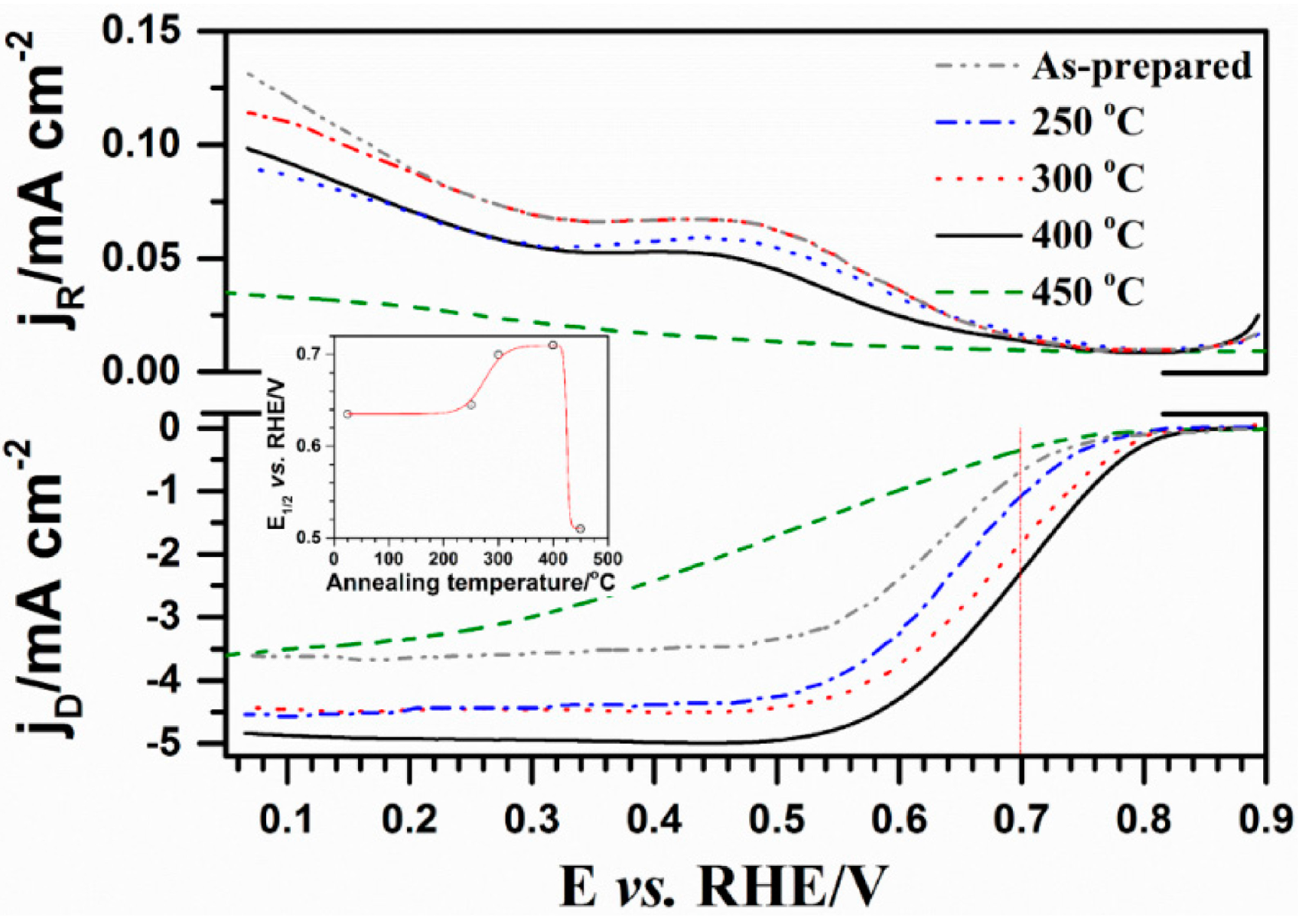
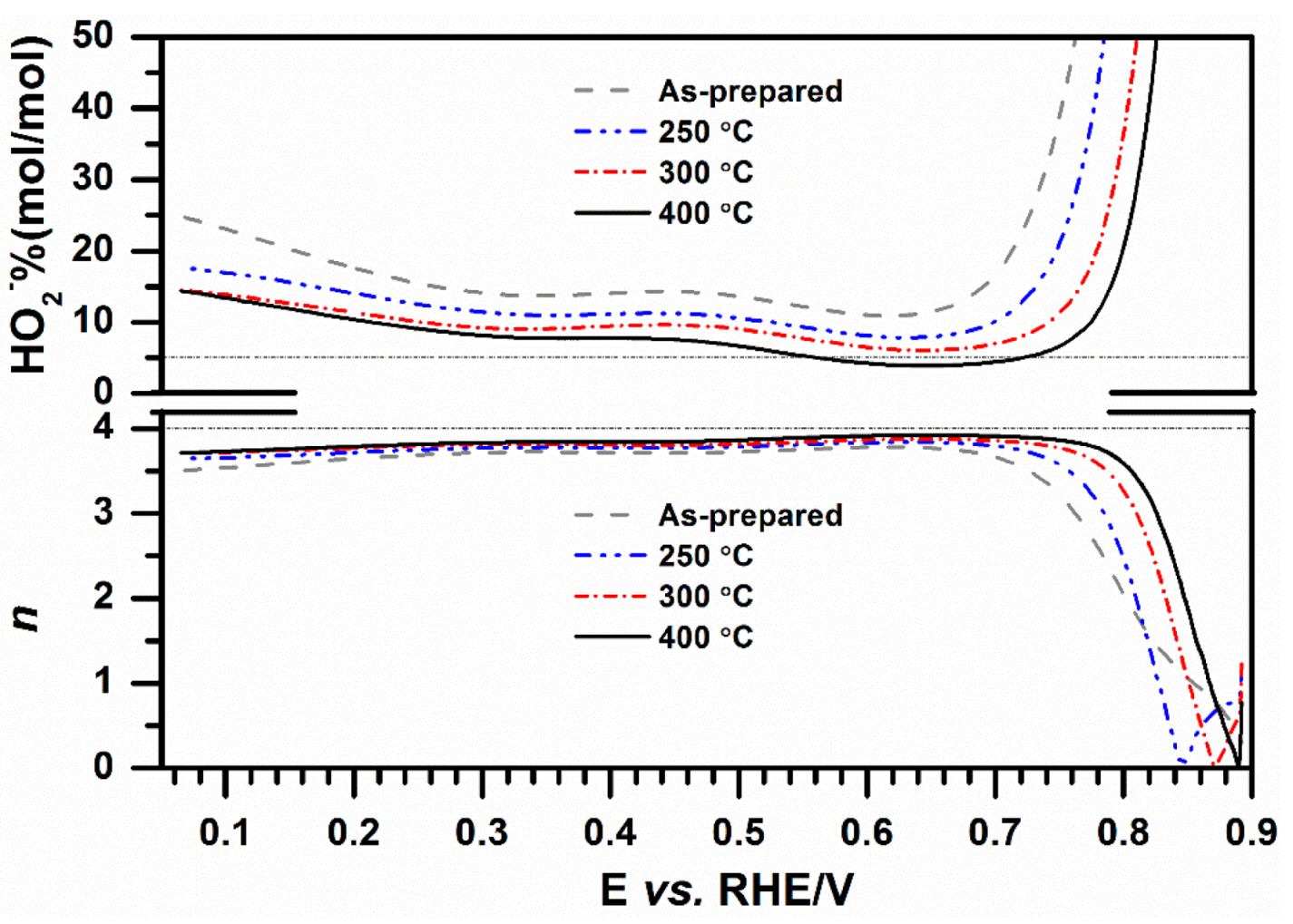
2.2. Influence of Heat-Treatment on Electrocatalytic Activity towards ORR

Figure 5 demonstrates the effect of heat-treatment temperature on the ORR activity of 20 wt. % CoS/C nanoparticles in O2-saturated 0.1 M KOH at a rotating speed of 2500 rpm as measured by the RRDE technique. The mass loading of CoS catalyst is 80 μg·cm−2 on the working disk. In the disk current density (jD) curves (down), the heat-treatment remarkably improves the ORR activity of 20 wt. % CoS/C nanoparticles in terms of the current density and the half-wave potential (E1/2, see the inset). The disk current density at 0.70 V is increased from 0.60 mA·cm−2 for the as-prepared sample to 2.22 mA·cm−2 for CoS-400 whereas only 0.33 mA·cm−2 is observed for CoS-450. The CoS-400 shows the plateau-like current density of 5.0 mA·cm−2 at a potential of lower than 0.52 V, which is close to the diffusion-limited current density expected for 4-electron pathway in 0.1 M KOH [14]. The half-wave potential is also enhanced from 0.64 V for the as-prepared sample to 0.71 V for CoS-400, and then reduced to 0.51 V for CoS-450. The value of 0.71 V is the highest value among non-precious metal chalcogenides [3,11] and very close to 0.77 V for RuSex/C [20]. At 2500 rpm, in comparison, jR (HO2 oxidation) is much smaller than jD (oxygen reduction), meaning that H2O was the main product of ORR catalyzed by the prepared catalysts. Additionally, the ring current density (jR) is decreased with increase of the annealing temperature, further suggesting the positive effect of the heat-treatment on the electrocatalytic activity of CoS/C catalyst under the investigated conditions.
Figure 5. Ring (top) and disk (down) current density from RRDE measurements of 20 wt. % CoS/C samples after annealing at different temperature in O2-saturated 0.1 M KOH at 25 °C with a sweep rate of 5 mV s−1 at a rotating speed of 2500 rpm. Inset shows the half-wave potential (E1/2) as a function of the annealing temperature. The CoS mass loading on the disk electrode is 80 μg·cm−2.
Catalysts 05 01211 g005
Furthermore, the electrocatalytic activity towards ORR has been further evaluated based on the RRDE measurements: the electron reduction pathway and the percentage of H2O product as a function of annealing temperature, see Figure 6. The HO2% and the number of electrons transferred (n) was calculated by the following two equations:
HO 2 % = 200 × I R / N I D + I R / N
n = 4 × I D I D + I R / N
where ID, IR and N is disk current, ring current and collection efficiency (0.26), respectively. With increase of the annealing temperature from room temperature to 400 °C, the H2O product is decreased from 11.0% to 4.3% at the potential of 0.60 V with a mass loading of 80 μg·cm−2. The H2O product of 4.3% for CoS-400 at 0.60 V is much less than that of ca. 8% for Co3O4/rmGO and comparable with Co3O4/N-rmGO with a mass loading of 100 μg·cm−2 [21]. Also, the number of electrons transferred is increased from 3.5 for the as-prepared sample to 3.9 for CoS-400 in the range from 0.10 V to 0.72 V, which is comparable with that for Co3O4/rmGo and Co3O4/N-rmGO [21]. The results suggest that CoS-400 has promising electrocatalytic activity for ORR in 0.1 M KOH.
Figure 6. Molar fraction of HO2 formation and electron transfer number n at different potentials calculated from rotating ring-disk electrode (RRDE) curves in Figure 3. The fraction of HO2 formation was calculated according to Equation (1) and the electron transfer number (n) was evaluated from Equation (2). The collection efficiency N of 0.26 was used for all the calculations.
Catalysts 05 01211 g006

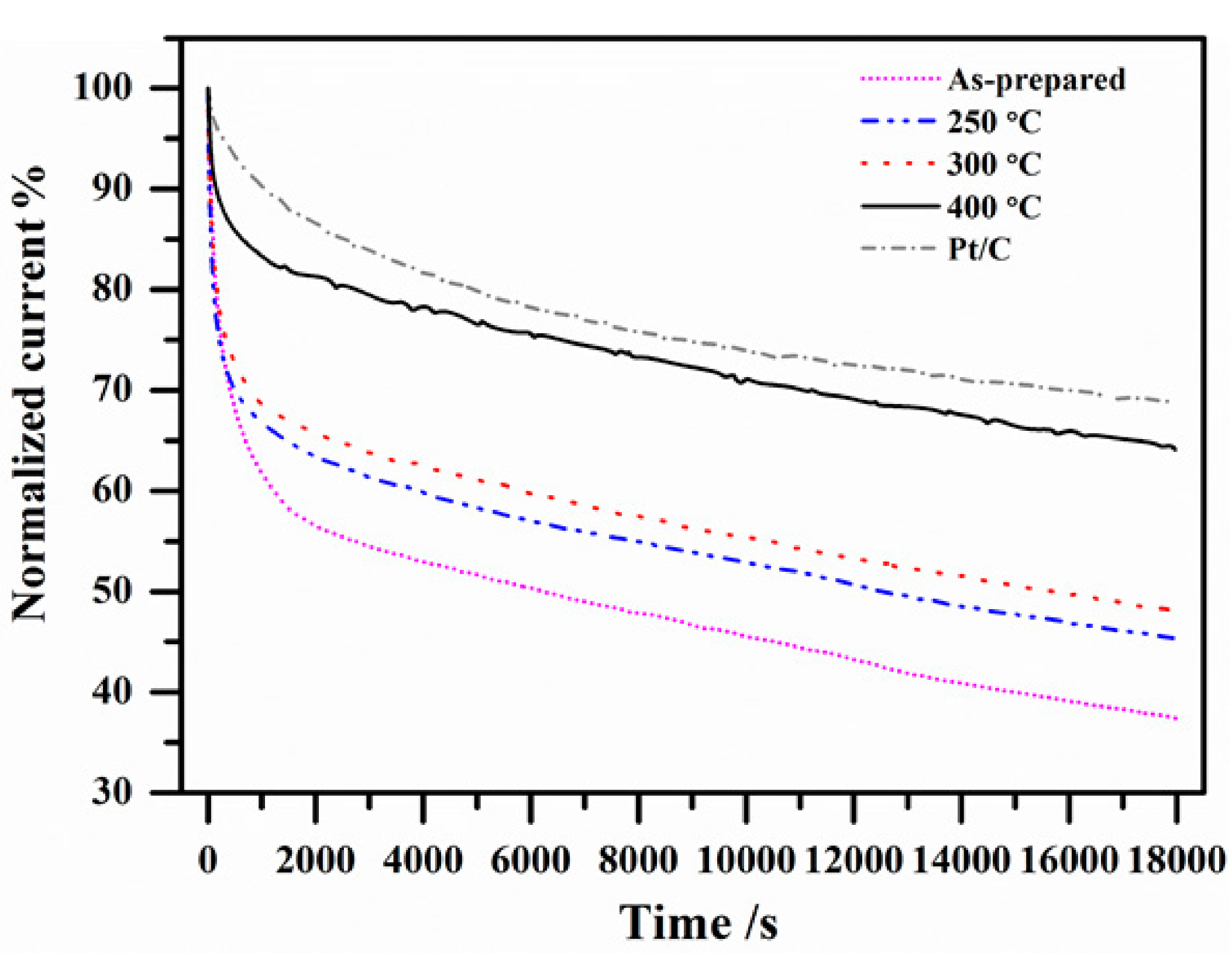
2.3. Electrocatalytic Stability

The long-term stability is the other important parameter for non-precious metal catalysts. Commercial 20 wt. % Pt/C (E-TEK) is usually used as the reference to evaluate the catalytic activity and durability of non-Pt catalysts in alkaline medium [4,8,21,22,23]. Figure 7 depicts the effect of the annealing temperature on the electrocatalytic stability of 20 wt. % CoS/C. The normalized current (I/I0%) means a percentage of the determined current (I) at operating time over the initial current (I0) at a fixed potential E. In our case, the potential value of 0.66 V was chosen for the accelerated stability test based on Dai’s work [14,21]. After 18,000 s of continuous operation, the decrease in activity is observed, e.g., 60% for the as-prepared sample and 35% for CoS-400, suggesting that the annealed treatment markedly improves the electrocatalytic stability of CoS/C catalyst. The decrease value in current for CoS-400 is very close to that of 30% for Pt/C as reported in Ref. [21], where a 20%–48% decrease in current for Pt/C was determined in 0.1–6 M KOH with a high mass loading of 240 μg·cm−2.
Figure 7. Chronoamperometric response (percentage of current retained vs. operation time) of 20 wt. % CoS/C after annealed at different temperature and 20 wt. % Pt/C (E-TEK) on a glassy carbon electrode kept at 0.66 V vs. RHE in O2-saturated 0.1 M KOH at 25 °C. Mass loading on the disk electrode is 80 μg·cm−2 for CoS and Pt.
Catalysts 05 01211 g007

3. Materials and Methods

3.1. Chemicals

All the chemicals with analytical grade were used as received without further purification. Vulcan XC-72R carbon, received from CABOT Co. (Shanghai, China), was activated at 400 °C under a high purity nitrogen atmosphere for 4 h before use.

3.2. Synthesis of Carbon-Supported CoS Nanocatalyst

Carbon-supported CoS nanocatalyst was directly synthesized in a solvothermal route using cobalt nitrate (Co(NO3)2·6H2O) and thiourea (CH4N2S) as the source of Co and S, which followed the similar procedure for CoS2 nanoparticles as described in [24]. For 20 wt. % CoS/C, typically, 0.8 mmol Co(NO3)2·6H2O, 2.4 mmol CH4N2S, and 0.3 g carbon (Vulcan XC-72R) were mixed in 80 mL absolute ethanol and then removed into 100 mL Teflon-lined stainless steel autoclave. The sealed autoclave was kept at 200 °C for 24 h and then cooled down to room temperature. The final product was collected after six cycles of centrifugation and resuspension with distilled water and ethanol and drying at 60 °C for 6 h. Finally, the obtained sample was further annealed at 250, 300, 400 and 450 °C for 3 h under high purity nitrogen atmosphere and denoted as as-prepared, CoS-250, -300, -400 and -450, respectively.

3.3. Structural Characterization and Electrochemical Measurements

Powder X-ray diffraction (XRD) patterns were recorded on a Shimadzu XRD-6000 X-ray diffractometer (Kyoto, Japan) (Cu Kα radiation, λ = 0.15406 nm) at tube current of 30 mA and tube potential of 40 kV from 10° to 60°/2θ with a scan speed of 2°·min−1.
Transmission electron microscopy (TEM) and high-resolution transmission electron microscopy (a resolution of 0.19 nm) were carried out on a JEOL JEM-2010 electron microscope (Tokyo, Japan) at 200 kV.
The rotating ring-disk electrode (RRDE) measurements were carried out at 25 °C using an interchangeable Pine ring-disk electrodes with a bi-potentiostat (CHI760C, ChenHua Instruments Co., Shanghai, China) and a rotation control system (Pine Instruments, Grove, PA, USA). The Pt ring electrode with a geometric area of 0.152 cm2 was potentiostated at 1.2 V, where the detection of peroxide is diffusion limited. The disk electrode was glassy carbon with a geometric area of 0.162 cm2. The counter and the reference electrodes were a Pt ring and a saturated calomel electrode. All potentials reported in this paper are referred to a reference hydrogen electrode (RHE). The current density on the disk and the ring was calculated based on the corresponding geometric area, respectively. Before use, the glassy carbon disk electrode was polished with a 5 A alumina powder, and washed in water and ethanol by ultrasound. The working electrode was prepared by depositing homogeneous catalyst ink on the glassy carbon disk, which was formed by dispersing 9.0 mg 20 wt. % CoS/C powder in a mixture solvent of 250 mL Nafion® solution (5 wt. %, DuPont, Shanghai, China) and 1250 mL water in an ultrasonic bath for 2 h. Newly prepared 0.1 M KOH solution (pH = 12.97) was used as the electrolyte. Prior to linear-sweep voltammograms (LSV), the electrode was subjected to 50 cycles of cyclic voltammetry under high purity argon atmosphere to clean the surface. After this cleaning, the LSVs under saturated oxygen were recorded by scanning the disk potential vs. RHE at 5 mV·s−1 at the rotating speed of 2500 rpm.

4. Conclusions

In summary, carbon-supported CoS electrocatalyst, as one of non-precious metal chalcogenides, has been directly prepared in a facile solvothermal route. The annealed treatment has significantly improved the electrocatalytic activity and long-term stability of CoS catalyst towards ORR in alkaline medium with increase of annealed temperature from room temperature to 400 °C. The CoS catalyst that annealed at 400 °C has the maximum electrocatalytic performance among the annealed CoS samples and shows promising applications for alkaline fuel cells as one of non-precious metal cathodes.

Acknowledgments

This work was supported by the National Basic Research Program of China (Grant No. 2011CBA00508) and Beijing Engineering Center for Hierarchical Catalysts.

Author Contributions

Y.J. F, P.G. T. and D.Q. L conceived and designed the experiments; H.H. Z and J.M. X performed the experiments; H.H. Z and J.M. X analyzed the data; J.M. X contributed reagents/materials/analysis tools; Y.J. F and H.H. Z wrote the paper.

Conflicts of Interest

The authors declare no conflict of interest. The founding sponsors had no role in the design of the study; in the collection, analyses, or interpretation of data; in the writing of the manuscript, and in the decision to publish the results.

References

  1. Wang, Y.; Chen, K.S.; Mishler, J.; Cho, S.C.; Adroher, X.C. A review of polymer electrolyte membrane fuel cells: Technology, applications, and needs on fundamental research. Appl. Energy 2011, 88, 981–1007. [Google Scholar] [CrossRef]
  2. Miller, M.; Bazylak, A. A review of polymer electrolyte membrane fuel cell stack testing. J. Power Sources 2011, 196, 601–613. [Google Scholar] [CrossRef]
  3. Feng, Y.; Gago, A.; Timperman, L.; Alonso-Vante, N. Chalcogenide metal centers for oxygen reduction reaction: Activity and tolerance. Electrochim. Acta 2011, 56, 1009–1022. [Google Scholar] [CrossRef]
  4. Guo, J.; Li, H.; He, H.; Chu, D.; Chen, R. CoPc- and CoPcF16-modified Ag nanoparticles as novel catalysts with tunable oxygen reduction activity in alkaline media. J. Phys. Chem. C 2011, 115, 8494–8502. [Google Scholar] [CrossRef]
  5. Robertson, N.J.; Kostalik, H.A.; Clark, T.J.; Mutolo, P.F.; Abruña, H.D.; Coates, G.W. Tunable High Performance Cross-Linked Alkaline Anion Exchange Membranes for Fuel Cell Applications. J. Am. Chem. Soc. 2010, 132, 3400–3404. [Google Scholar] [CrossRef] [PubMed]
  6. Tamain, C.; Poynton, S.D.; Slade, R.C.T.; Carroll, B.; Varcoe, J.R. Development of cathode architectures customized for H2/O2 metal-cation-free alkaline membrane fuel cells. J. Phys. Chem. C 2007, 111, 18423–18430. [Google Scholar] [CrossRef]
  7. Wu, H.; Chen, W. Copper nitride nanocubes: Size-controlled synthesis and application as cathode catalyst in alkaline fuel cells. J. Am. Chem. Soc. 2011, 133, 15236–15239. [Google Scholar] [CrossRef] [PubMed]
  8. Yang, D.S.; Bhattacharjya, D.; Inamdar, S.; Park, J.; Yu, J.S. Phosphorus-doped ordered mesoporous carbons with different lengths as efficient metal-free electrocatalysts for oxygen reduction reaction in alkaline media. J. Am. Chem. Soc. 2012, 134, 16127–16130. [Google Scholar] [CrossRef] [PubMed]
  9. Susac, D.; Zhu, L.; Teo, M.; Sode, A.; Wong, K.C.; Wong, P.C.; Parsons, R.R.; Bizzotto, D.; Mitchell, K.A.R.; Campbell, S.A. Characterization of FeS2-Based Thin Films as Model Catalysts for the oxygen reduction reaction. J. Phys. Chem. C 2007, 111, 18715–18723. [Google Scholar] [CrossRef]
  10. Zhu, L.; Susac, D.; Teo, M.; Wong, K.C.; Wong, P.C.; Parsons, R.R.; Bizzotto, D.; Mitchell, K.A.R.; Campbell, S.A. Investigation of CoS2-based Thin Films as Model Catalysts for the Oxygen Reduction Reaction. J. Catal. 2008, 258, 235–242. [Google Scholar] [CrossRef]
  11. Zhao, C.; Li, D.; Feng, Y. Size-controlled hydrothermal synthesis and high electrocatalytic performance of CoS2 nanocatalysts as non-precious metal cathode materials for fuel cells. J. Mater. Chem. A 2013, 1, 5741–5746. [Google Scholar] [CrossRef]
  12. Feng, Y.J.; He, T.; Alonso-Vante, N. In situ Surfactant-Free Synthesis and ORR- Electrochemistry of Carbon-Supported Co3S4 and CoSe2 Nanoparticles. Chem. Mater. 2008, 20, 26–28. [Google Scholar] [CrossRef]
  13. Feng, Y.J.; He, T.; Alonso-Vante, N. Carbon-Supported CoSe2 Nanoparticles for Oxygen Reduction Reaction in Acid Medium. Fuel Cells 2010, 10, 77–83. [Google Scholar]
  14. Wang, H.; Liang, Y.; Li, Y.; Dai, H. Co1−xS-Graphene Hybrid: A High-Performance Metal Chalcogenide Electrocatalyst for Oxygen Reduction. Angew. Chem. Int. Ed. 2011, 50, 10969–10972. [Google Scholar] [CrossRef] [PubMed]
  15. Bezerra, C.W.B.; Zhang, L.; Liu, H.; Lee, K.; Marques, A.L.B.; Marques, E.P.; Wang, H.; Zhang, J. A review of heat-treatment effects on activity and stability of PEM fuel cell catalysts for oxygen reduction reaction. J. Power Sources 2007, 173, 891–908. [Google Scholar] [CrossRef]
  16. Cheng, H.; Yuan, W.; Scott, K. Influence of Thermal Treatment on RuSe Cathode Materials for Direct Methanol Fuel Cells. Fuel Cells 2007, 7, 16–20. [Google Scholar] [CrossRef]
  17. Cheng, H.; Yuan, W.; Scott, K. The influence of a new fabrication procedure on the catalytic of ruthenium-selenium catalysts. Electrochim. Acta 2006, 52, 466–473. [Google Scholar] [CrossRef]
  18. Dresselhaus, M.S.; Jorio, A.; Hofmann, M.; Dresselhaus, G.; Saito, R. Perspectives on carbon nanotubes and graphene Raman spectroscopy. Nano Lett. 2010, 10, 751–758. [Google Scholar] [CrossRef] [PubMed]
  19. Bao, S.-J.; Li, Y.B.; Li, C.M.; Bao, Q.L.; Lu, Q.; Guo, J. Shape evolution and magnetic properties of cobalt sulfide. Cryst. Growth Des. 2008, 8, 3745–3749. [Google Scholar] [CrossRef]
  20. Delacôte, C.; Bonakdarpour, A.; Johnston, C.M.; Zelenay, P.; Wieckowski, A. Aqueous-based synthesis of ruthenium-selenium catalyst for oxygen reduction reaction. Faraday Discuss. 2008, 140, 269–281. [Google Scholar] [CrossRef] [PubMed]
  21. Liang, Y.; Li, Y.; Wang, H.; Zhou, J.; Wang, J.; Regier, T.; Dai, H. Co3O4 nanocrystals on graphene as a synergistic catalyst for oxygen reduction reaction. Nat. Mater. 2011, 10, 1780–1786. [Google Scholar] [CrossRef] [PubMed]
  22. Tuci, G.; Zafferoni, C.; D’Ambrosio, P.; Caporali, S.; Ceppatelli, M.; Rossin, A.; Tsoufis, T.; Innocenti, M.; Giambastiani, G. Tailoring carbon nanotube N-dopants while designing metal-free electrocatalys for the oxygen reduction reaction in alkaline medium. ACS Catal. 2013, 3, 2108–2111. [Google Scholar] [CrossRef]
  23. Lee, J.S.; Park, G.S.; Lee, H.I.; Kim, S.T.; Cao, R.; Liu, M.; Cho, J. Ketjenblack carbon supported amorphous manganese oxides nanowires as highly efficient electrocatalyst for oxygen reduction reaction in alkaline solution. Nano Lett. 2011, 11, 5362–5366. [Google Scholar] [CrossRef] [PubMed]
  24. Han, J.-T.; Huang, Y.-H.; Huang, W. Solvothermal synthesis and magnetic properties of pyrite Co1−xFexS2 with various morphologies. Mater. Lett. 2006, 60, 1805–1808. [Google Scholar] [CrossRef]

