How to Determine the Core-Shell Nature in Bimetallic Catalyst Particles?


Department of Chemical Engineering, Delft University of Technology, Julianalaan 136, 2628BL Delft, The Netherland
*
Author to whom correspondence should be addressed.
Catalysts 2014, 4(4), 375-396; https://doi.org/10.3390/catal4040375
Submission received: 31 August 2014
/
Revised: 12 November 2014
/
Accepted: 18 November 2014
/
Published: 28 November 2014
(This article belongs to the Special Issue Synthesis of Nanostructured Catalytic Materials from Microemulsions)
Abstract
:Nanometer-sized materials have significantly different chemical and physical properties compared to bulk material. However, these properties do not only depend on the elemental composition but also on the structure, shape, size and arrangement. Hence, it is not only of great importance to develop synthesis routes that enable control over the final structure but also characterization strategies that verify the exact nature of the nanoparticles obtained. Here, we consider the verification of contemporary synthesis strategies for the preparation of bimetallic core-shell particles in particular in relation to potential particle structures, such as partial absence of core, alloying and raspberry-like surface. It is discussed what properties must be investigated in order to fully confirm a covering, pin-hole free shell and which characterization techniques can provide such information. Not uncommonly, characterization strategies of core-shell particles rely heavily on visual imaging like transmission electron microscopy. The strengths and weaknesses of various techniques based on scattering, diffraction, transmission and absorption for investigating core-shell particles are discussed and, in particular, cases where structural ambiguities still remain will be highlighted. Our main conclusion is that for particles with extremely thin or mono-layered shells—i.e., structures outside the limitation of most imaging techniques—other strategies, not involving spectroscopy or imaging, are to be employed. We will provide a specific example of Fe-Pt core-shell particles prepared in bicontinuous microemulsion and point out the difficulties that arise in the characterization process of such particles.

1. Introduction
For particles in the size range beneath 5 nm, optical, chemical and physical properties of the nanocrystal surface are strongly altered compared to those of bulk material [1,2]. Moreover, the high surface-to-volume ratio makes them suitable candidates for catalysis applications [3,4]. Such particles may be composed of one or more elements, typically metals, arranged into mixed or structured configurations. For catalysis purposes special attention has been drawn to bimetallic core-shell nanoparticles, since such particles maximize the use and exposure of the catalytically active surface material. Apart from the obvious benefit of a core-shell structure, namely adding a bulk property such as reduction of particle mass while maintaining surface properties, it is believed that geometric effects, e.g., lattice strain, caused by the underlying structure play a key role in enhancing the catalytic properties of the surface metal [5,6,7,8,9].
There is a wide spectrum of strategies used for producing core-shell nanoparticles, relying on precipitation, decomposition, surface enrichment, leaching or deposition to obtain core-shell structured particles. The segregation into two spatially separated phases—core and shell—commonly relies on differences in physical and chemical properties between the two metals, e.g., differences in reduction potentials or in affinity for adsorbates, or by the sequence in which the synthesis is carried out. In the first case, the resulting structure is close to local thermodynamic equilibrium whereas in the second case the material is kinetically trapped in the structure.
Particle formation through precipitation is commonly carried out by reduction of metal containing precursors in aqueous or organic solution at high [10,11] or low [12,13,14] temperature. Decomposition of thermally unstable metal-organic precursors is another, relatively classical route that lately has been refined and tuned [4,7,15]. Furthermore, alloy nanoparticles can be treated, either thermally [16,17] or by adsorbates [6,18], in such a way that one metal component thermodynamically prefers to segregate to the surface. Removing a metal component from the surface of an alloy particle through leaching can be done (electro)chemically [19,20]. By depositing one metal on top of the other, the core particle can be used as a seed or nucleation center when e.g., reducing a second metal precursor [11,21,22]. Alternatively, the outermost atoms of the core particle are sacrificed by using galvanic displacement of the core metal in favor of the shell metal [13,23,24]. Irrespective of the synthesis route, the technique ideally needs to ensure controllability of the core size and shell thickness as well as the formation of a uniform and intact shell. This turns out to be neither trivial nor easily achieved.
As a way to control the growth of nanoparticles, microemulsion techniques can be employed, in which the nucleation and growth of the particles takes place within the confined space of inversed micelles or channels [25]. Microemulsions are nanostructured dispersions of two immiscible liquids, stabilized interfacially by surface active molecules. The key aspect of most microemulsion techniques is that water-phase nanoreactors can be tuned in size and yield monodispersed nanoparticles [4,25]. Recently, we have developed a synthesis method based on bicontinuous microemulsions that is capable of high yield production of ultrafine, monodispersed nanoparticles, see [26] and references therein. By expanding this method we have explored the possibilities of synthesizing also core-shell nanoparticles in a dense heptane/water/AOT bicontinuous microemulsion system. Using this example we will discuss some of the specific characterisation challenges that are associated with nanoparticles produced in microemulsions.
For microemulsion techniques as well as aqueous synthesis techniques, it is common to use galvanic displacement for adding the shell material, relying on the difference in the electrochemical reducing potential between the core and the shell metal [13,27,28,29]. It is here assumed that the dominating mechanism involved is replacement of core surface atoms with shell precursor ions, preventing the reduction of shell ions exclusively on the core surface in the system. The success of galvanic replacement appears to largely depend on the reaction conditions, the metals used and the compatibility between them. It is important to point out that galvanic replacement in aqueous media is strictly confined to the aqueous chemistry of the metals involved. Many non-noble metals like iron or copper form oxides at neutral or high pH, limiting the reducing potential of the surface core atoms [13].
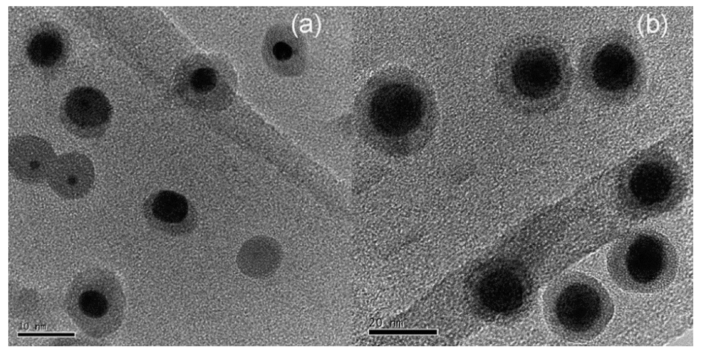
When relying on galvanic displacement for depositing the shell, a uniform dispersion of the shell precursor is crucial. This is especially critical when the synthesis takes place within a microemulsion where the dispersion naturally is limited by the exchange between the micelles/channels. In case of excessive amounts of shell precursor present, the core particles could be completely oxidized upon the formation of particles consisting of shell material. In contrast, the core particles could be left with incomplete shells if the shell precursor concentration is very low [30,31], see Figure 1. Tojo et al., suggested that since the surfactant flexibility affects intermicellar exchange, choosing a surfactant accordingly can play a crucial role in steering the final structure towards core-shell type structure or a more alloyed structure.
Figure 1.
TEM micrographs of Ni-core Au-shell nanoparticles prepared in microemulsion using galvanic displacement for shell deposition. Core-shell particles prepared with a molar ratio of water to surfactant of 5: (a) display an example of inhomogeneous galvanic displacement whereas particles prepared with a higher ratio, 9; (b) have more even shell thicknesses (Reprinted with permission from [30], 2009, Elsevier).

One major challenge when synthesizing core-shell particles is to ensure a smooth and pin-hole free shell covering a well-defined core. There are many examples where the final structure deviates from this ideal. Upon deposition of the shell material on the core by a second-step reduction of metal ions, small metal particles can nucleate on the surface of the core and remain as spheres decorating the core, also referred to as “raspberry structure”. Such structures have been obtained by addition of polymeric surface active molecules, such as poly(vinylpyrrolidone) [32] or a polyethylene glycol-based polymer [33], preventing particle agglomeration. However, not fundamentally different structures were also obtained—albeit not intentionally—in core-shell synthesis routes based on hydrothermal synthesis [11], galvanic replacement in microemulsion [13,29] and sequential deposition [29]. High temperature annealing could smoothen such shells with the risk of sintering particles and hence reducing the active surface of the catalyst particles.
Another example of unwanted structures are hollow particles. Alongside the core-shell particles synthesized by a sequential deposition method [29] and a microemulsion method [14], hollow particles were also obtained, consisting of either mixed core and shell material or just the material in the shell. In addition, galvanic displacement has been used with the intention to create hollow particles [19]. By adding precursor material sequentially it is often assumed that a core-shell structure is achieved. Examples of both scenarios where, despite subsequent addition of the shell material, alloy particles were formed rather than core-shells are given in [34], and particles with an alloy core rather than a pure non-noble metal core in [27].
Although many synthesis strategies have been developed over the last years to improve controllability of the size, shape and shell thickness, the characterization step becomes utterly important in order not only to refine the synthesis routes to avoid any unwanted structures but also to correlate the final properties of the material with the true structure of the particles. In this contribution, the suitability of common characterization techniques for investigating the true nature of core-shell catalyst particles will be assessed and graded. In doing so, we have taken the liberty of citing only those works as deemed relevant to illustrate a particular point rather than making an extensive review of all work done in the field.
In the Methods section, we describe the instrumental aspects of the techniques as are currently considered for the characterization of core shell particles. This part may readily be skipped by those readers who are familiar with most if not all techniques. The experimental procedure for our core-shell synthesis in bicontinuous microemulsion is also described.
2. Results
The aspects of the critical assessment of the available techniques are summarized in Table 1 and include depth and spatial resolution, composition and elemental distribution, geometrical structure and porosity, and other chemical or physical properties. The results are discussed below and are summarized in their entirety in Table 2. The following section will discuss the various entries in successive order.

| Label used | − − | − | 0 | + | + + |
|---|---|---|---|---|---|
| Surface sensitivity | transmission | > 10 nm | 3–10 nm | 1–2 nm | < 1 nm |
| Spatial resolution | bulk | > 10 nm | 2–10 nm | 0.1–1 nm | < 0.1 nm |
| Composition | Signal strength, sensitivity to atom number, sensitivity to environment/neighboring atoms, oxidation state. | ||||
| Elemental distribution | Ability to determine the distribution of elements across the particle, alloying and crystal structure. | ||||
| Geometry/Porosity | Ability to determine particle size and geometry, particle dispersity and shell porosity. | ||||
| Technique | Type | Technique | Surface sensitivity | Spatial resolution | Composition | Elemental distribution | Geometry/Porosity | Other chemical or physical properties |
|---|---|---|---|---|---|---|---|---|
| Electron Microscopy | e−→e− | SEM, SEI, BEI | SEI + BEI − | ○ | n/a | - | -- | |
| TEM, HRTEM, STEM | -- | ++ | n/a | + | + | |||
| Electron Spectroscopy | e−→e− | EELS | Tr-EELS--Refl-EELS + | + | + | ++ | See TEM | |
| AES | + | ○ | ○ | + | ○ | Adsorption and chemisorption of gases | ||
| HAADF | -- | + | + | + | See TEM | |||
| e−→λ | EDX | - | ○ | + | - | -- | ||
| X-ray Spectroscopy | λ→λ | XRD | - | -- | + | ○ | -- | |
| λ→e− | XPS | + | -- | ++ | ++ | - | Organic surface contaminants | |
| Absorption spectroscopy | λ | XAS | -- | -- | + | + | + | Adsorbates/Ligands |
| λ | UV-vis | + | -- | ○ | - | ○ | SPR | |
| Other | AFM | ++ | + | -- | ○ | + | ||
| Cyclic Voltammetry | ++ | -- | + | - | + | Catalytic activity |
2.1. Electron Microscopy and Spectroscopy
Spotting individual particles on nanoscale, and even less so the potential core-shell structures therein, is for most standard SEM equipment too much of a challenge. SEM in conjunction with EDX microanalysis, however, offers a good alternative for bulk compositional analysis. TEM is commonly considered as perhaps the most, on its own, exhaustive imaging technique for determining core-shell structures in nanoparticles due to the high resolution achievable. However, the amount and accuracy of the information extracted depends strongly on the elemental composition of the particles and also on the quality of the instrument itself. Moreover, due to the fact that the electrons penetrate deep into if not through the sample, the response will inevitably contain mixed information from both the core and the shell phases [35], hence lacking the sensitivity to surface structure. The sub-nanometer resolution of some high resolution TEMs opens up the possibility to come close to spotting individual atoms within the nanoparticle [4,36,37]. Thereby, the distribution, crystal structure, particle size and dispersity can be visualized. For determining particle size in TEM the accuracy is limited since the size typically is uncertain to at least one or two lattice fringes, about 0.2 nm. For particles smaller than 2 nm, this induces a significant error, considering the difficulty in achieving perfectly monodispersed and homogeneous samples. In addition, beam heating during imaging resulting in particle melting or sintering can diffuse the particle boundaries. Furthermore, one obvious drawback in determining dispersity by using TEM is the tiny size of the area viewed relative to the entire sample [4]. Surface topography, particle distribution and crystal planes can be imaged using TEM but to extract compositional information an element specific signal detector is needed. Compositional profiling of individual nanoparticles is often sought for and enabled when suitable spectroscopy techniques are accompanied with the TEM/STEM setup, such as EDX, EELS, HAADF, in order to discriminate core from shell. There are examples where standard laboratory TEM with EDX provide sophisticated compositional profiling across individual core-shell particles with down to 1 nm steps. One example is the study of silver-core platinum-shell type particles by Wojtysiak et al., where profiling could help distinguishing core-shell particles from hollow Pt particles [29]. Even more impressive step resolution profiling is achieved with STEM-EELS setups [10,11,24,35] with examples for particles not more than 2 nm in diameter [38]. Although this kind of profiling struggles to exclude the presence of pores through the shell, which could only be estimated visually, standard EDX has been used as a tool to investigate the intactness of the shell. In a study on Ni/Au core-shell particles made in microemulsion by Chen et al., EDX was used to probe whether the core metal (Ni) had been oxidized in the presence of air through possible pores in otherwise the protective (Au) shell layer [30]. Further TEM compositional profiling methods are limited in determining possible alloying of two metals in bimetallic core-shell particles. An attempt to resolve the issue with inevitably combined signals from the core and shell was made by Mendis et al. [35]. By using STEM fitted with EELS and HAADF in combination with linear regression analysis, compositional profiles were made with resolution steps as small as 0.1 nm for a set of TiN-core Ti-oxide-shell and Cu-core Cu-oxide-shell particles. An analytical method was developed to determine the relative amount of each element within each region, i.e., core, interface and shell. Inaccuracy arises, however, due to non-uniform shell thickness of “real” particles using a model that assumes an idealized spherical geometry. Nonetheless, the model was able to give qualitative results for elemental compositions within each region.
Because of the shallow escape depth of Auger electrons, AES is the most surface sensitive among the electron scattering techniques. However, the measured signal is relatively weak as only a fraction of the excited Auger electrons will be detected, which in practice makes the signal-to-noise ratio a limiting factor for the resolution [39,40]. When using AES for compositional analysis it is important to keep in mind that the release of Auger electrons, and secondary electrons for that matter, from small core-shell type particles is rather different to that from flat surfaces. If the particle radius is smaller than the inelastic mean free path then all electrons generated inside the particle will escape without losing energy, hence corrupting the distinction between surface or shell and bulk or core signals [41,42]. An example of that was performed by Liu et al., who analyzed alumina supporting 2 nm sized silver nanoparticles [41]. An option for slightly larger core-shell particles is to perform a line scan, benefitting from the surface sensitivity despite the moderate resolution [42]. Upon excitation of a core electron the released energy can either generate the emission of an Auger electron or the emission of X-ray photons. The two processes are complementary and the likelihood for either of the two to take place depends on the atomic number of the element. For low atomic number elements the dominating process is Auger electron emission while heavier elements are more likely to undergo relaxation via X-ray emission. Hence, since low atomic number elements have higher Auger yields, AES is particularly sensitive to these materials [40,42].
For topographical analysis the imaging of SAM does not reach the same resolution as TEM, however, since AES is based on reflection rather than transmission it does not suffer from the intrinsic problem of mixed signals from core and shell.
2.2. X-ray Spectroscopies
Due to the simplicity, speed and availability of XRD, this technique is extensively used for bulk compositional and crystal structure analysis in core-shell particle characterization. Because of the relatively low resolution of XRD, direct information about the distribution of elements is lacking, but on the other hand, crystal structure data can be used to verify or deny presence of alloyed or pure phases within the sample. It is, however, important to note that the distinction between a mix of separate core material particles and shell material particles, and core-shell particles would still be a remaining difficulty. It has been attempted to overcome this limitation [43]. In a study by Camardese et al., with the purpose to study the shell thickness of about 10 μm sized Ni/Mn(OH)2 core-shell particles, two reference materials were chosen: one representing the core material only and the other being a physical mix of core and shell materials in the same proportions as the core-shell sample. Due to absorption of X-rays by the shell, the signal from the core is reduced as compared to the reference mix material. A model was created to correlate the experimental results. There are some advantages using the absorption of X-rays of the shell as a basis for determining the shell thickness; the analysis is based on a large portion of the sample as opposed to single particle profiling. Furthermore, the analysis is quick, cheap and sample preparation is easy. On the other hand, uniformity is assumed and the absorption effect will decrease with decreasing shell thickness until a point where the effect is negligible. For particles smaller than approximately 100 nm, broadening of the X-ray diffraction lines occurs, allowing size measurement based on the Scherrer’s equation [44]. This simple approximation is valid when the diffraction material is stress free, since stress contributes to peak broadening as well. The lower size limit for detection with XRD is in the range of 3 nm. An intrinsic limitation of XRD is the fact that amorphous phases cannot be detected. There are numerous examples of studies where the XRD diffractograms of bimetallic core-shell particles only show one of the two supposedly present phases [10]. In such cases, either one of the phases is “truly amorphous” or the crystallite size is under the detection limit of the XRD.
The fact that even standard XPS equipment reaches surface sensitivities as low as 1 nm makes XPS into a powerful tool for core-shell characterization, especially for particles with shell thicknesses larger than 1 nm [4,12,13,45]. Despite the high surface sensitivity, a sampling depth comparable to the outermost atomic layer still cannot be reached [34]. In order to achieve more surface sensitive information there is an option to vary the emission angle in Angular Resolved XPS, ARXPS. However, this technique requires flat surfaces which makes it less suitable for nanoparticle analysis. The second option is to go for lower excitation energies. For this purpose, other sources than conventional laboratory sources like Al Kα or Mg Kα would be required, since the contribution from the topmost surface layer otherwise only accounts for about 30% of the total signal. Utilizing a synchrotron source and Excitation-energy Resolved XPS (ERXPS) represents one option for discriminating depth profiling of sub-nanometer scale. With the purpose of exploring the suitability of ERXPS for core-shell characterization, Merzlikin et al., investigated a set of gold-core platinum-shell fuel cell catalyst particles. By using 10 nm gold nanoparticles as seeds for the nucleation and growth of small platinum nanoparticles on its surface through reduction by ascorbic acid, the core-shell particles were synthesized and subsequently supported on a standard carbon support [34]. The catalyst particles were then analyzed in a synchrotron-based ERXPS. By correlating the relative intensities of the Au and Pt 4f peaks as a function of excitation energies with the escape depth, a composition-depth profile could be created. Interestingly, the results show no enrichment of Pt at the surface of Au, but rather strong indications of an Au-Pt alloy type or possibly a mix between pure Au and pure Pt particles, despite the sequence of the synthesis route.
In the classical route to destructive depth profiling in XPS, layer by layer is removed from the surface by ion sputtering with consequent XPS measurements. However, the success of this approach in the context of nanometer sized core-shell particles relies on the particles being fixed in position when shot at with the sputtering gun [13,46].
Since XPS is also sensitive to organic adsorbates it can be used to detect remnants from the synthesis steps, for example the presence of surfactants in case the particles were made in microemulsion [47].
2.3. Absorption Spectroscopies
XAS provides an option for compositional analysis due to the element specific characteristics, but nonetheless XAS is a bulk analysis technique. One advantage with XAS over other bulk techniques like SEM with EDX is the possibility of doing in situ measurements, an approach that has been increasingly used in for example fuel cell catalyst applications [24,48].
Since the technique is based on measuring the average electronic state and local coordination on a per-atom basis, XAS provides an estimate of particle size, possibly only monometallic. Further information about the surface structure can be achieved thanks to the possibility to probe metal-adsorbate bonding. This is not only useful in cases where the surface roughness and porosity is to be determined but also in the case of catalyst poisoning, e.g., carbon monoxide adsorption to fuel cell catalysts [49].
While studying bimetallic Au/Pd catalyst particles, Balerna et al. demonstrated how XANES and EXAFS can be used to distinguish alloy particles from surface enrichment of one metal on top of the other [15]. By studying the nearest-neighbor ratio for Au and Pd in particles prepared via two different synthesis routes, the degree of alloying versus core-shell type structure was estimated. Kuttiyiel et al., used XANES and EXAFS to verify the oxidation state of the Ni-core and to check the alloying of Au and Pd in the shell for their 4 nm sized AuPd-shell Ni-core particles [24]. Considerable contributions in this field have also been done by the group of Eichhorn [50,51,52].
Photons in the UV and visible region do not have sufficient energy to penetrate as deeply into a sample as higher energy photons like X-rays but are absorbed at the surface, making UV-vis spectroscopy relatively surface sensitive. Although UV-vis spectroscopy provides an easy and cheap means for compositional analysis, it is limited to bulk analysis. Furthermore, some metals are more suited for UV-vis analysis than others; gold being an example of a metal which displays distinct optical plasmon absorbances in the visible range [53]. One major application for UV-vis measurements in the characterisation of core-shell particles is to monitor the progress of the particle formation or shell deposition in situ [11,33]. Naturally this holds for liquid-phase synthesis routes. In a study on Au-core SnO2-shell nanoparticles, absorption spectra consequently taken during the shell deposition, starting from the pure core particles, gave information about the shell formation kinetics [11]. In another study, on Au-core Pt-shell particles the gradual disappearance of the plasmon peak for gold as platinum was deposited, was used as an indication for “complete” coverage of the shell [54]. Furthermore, UV-vis has been used to verify that no uncoated core particles are present alongside the core-shell particles, in terms of absent core-material absorption bands [14].
UV-vis spectroscopy can to a certain extent be used for particle size measurements, however, the contribution of the particle size to the absorption spectra becomes less and less significant with decreasing particle size [55]. Some disadvantages include the requirement of a certain degree of monodispersity and of regular shaped particles in order to achieve accurate measurements. Moreover, the particles need to be in a stable dispersion in order to be analyzed as the optical properties are sensitive to agglomeration.
2.4. Other
Being a mechanical imaging technique, detailed information about elemental composition in the sample is not available through AFM, but unlike other 2D imaging techniques like SEM, AFM generates a 3D image of the surface, that can be valuable when determining particle distribution on a catalyst support as well as particle geometry and agglomeration [21,53,56]. With the intention to examine the extent of shell coverage, Kumar et al., used AFM to characterize their 3 nm sized Au-core Pt-shell particles. After depositing approximately five monolayers of Pt on the gold particles, the coverage was visually determined and compared with complementary results from electrochemical analysis [23]. In practice, however, the resolution is limited by the tip radius and without element specific contrasts it is difficult to distinguish core and shell material at this resolution.
Techniques like CV are intrinsically surface specific techniques. Naturally electrochemical activity measurements provide key information on the suitability of the catalyst particles for their final application in terms of reaction order, kinetics, activation barriers, side reactions, durability etc., In addition, electrochemical techniques can be used in characterization of catalyst nanoparticles. Surface redox reactions are element specific and can be used for compositional analysis; either the surface atoms can be stripped off the surface by oxidation potentials or characteristic adsorption and desorption of other elements, e.g., O, CO or H, on the surface can be measured [8,12,24,29]. In an experiment using CO stripping as characterization method for investigating the surface composition of Ru-core Pt-shell nanoparticles Ochal et al., could demonstrate a Pt shell free from Ru. For the sample consisting of supposedly core-shell type particles the main CO stripping peak is shifted relative to bulk Pt and bulk Ru, but may come from either pure core-shell particles or a shell consisting of both metals. The latter structure could be ruled out by performing CO stripping experiments on several reference materials. Since Ru is easily oxidized and dissolved at negative potentials, a redistribution of Ru takes place causing instability of the CO stripping peaks for reference materials containing surface exposed Ru. Such movement of Ru in the system is not observed for pure core-shell particles where the Ru is fully encapsulated [52].
The platinum-coated silver nanoparticles synthesized by Wojtysiak et al., through different routes exhibit silver stripping (removal of silver from the surface) to varying extent. For the particles synthesized using a stronger reducing agent, a voltammogram similar to pure polycrystalline platinum is achieved and very little silver is stripped off the surface at 0.6 V. This led to the conclusion that a relatively pin-hole free shell was obtained and a minimum required shell thickness was estimated [29].
2.5. Core-Shell Particles Made in Microemulsions
When synthesizing core-shell nanoparticles in microemulsion the surfactant molecules prevent particles from agglomeration and hence enable high yield and monodispersity, due to the affinity for the surfactant head group to stick to the metal surface. However, upon completion of the synthesis, any remaining surfactants on the metal surface will affect the chemical and physical properties of the nanoparticles.
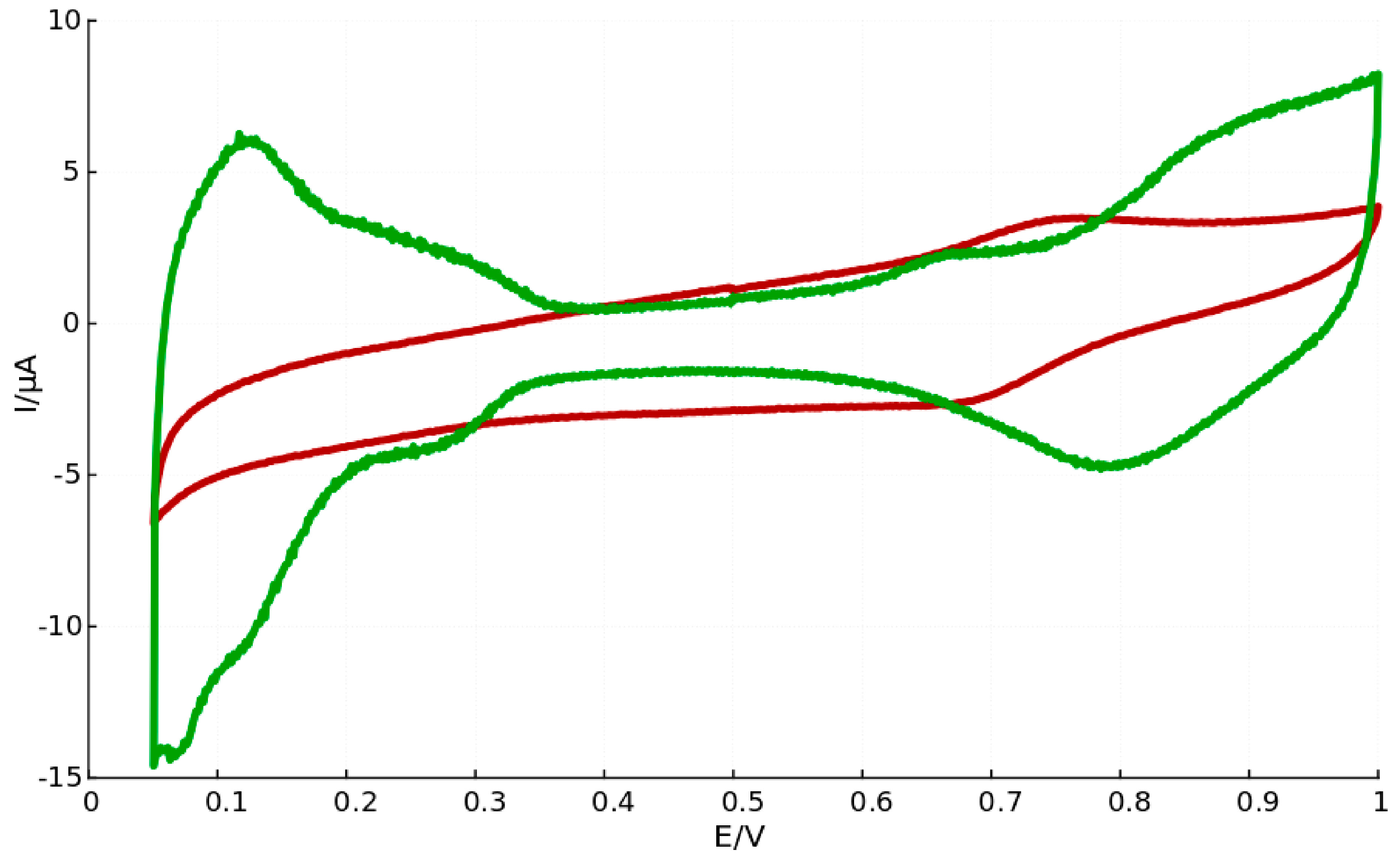
It is believed that surfactant molecules that remain adsorbed to the catalyst particle surface directly influence the catalytic performance since surface active sites are blocked [47]. The catalytic performance of the core-shell particles synthesized by us in bicontinuous microemulsion seem to agree with such arguments, since platinum characteristic peaks are absent in the voltammogram recorded for core-shell particles produced leaving out the washing procedure, as can be seen in Figure 2.
Figure 2.
Cyclic voltammograms for Fe-core Pt-shell nanoparticles prepared in microemulsion, where particles after thorough washing (green curve) exhibit characteristic Pt-peaks and particles with remaining surfactants (red curve) lack this feature.
Figure 2.
Cyclic voltammograms for Fe-core Pt-shell nanoparticles prepared in microemulsion, where particles after thorough washing (green curve) exhibit characteristic Pt-peaks and particles with remaining surfactants (red curve) lack this feature.

On the other hand it has been suggested that this effect may depend on surfactant type and hence where they bind to the metal surface [57]. Newton et al., show an example of Pt nanoparticles with the non-ionic surfactant NP9 adsorbed on the surface that show similar activity to surfactant-free Pt nanoparticles, meanwhile Pt nanoparticles with adsorbed cationic TTAB show a complete absence of Pt characteristics.
Surfactant present on the surface of nanoparticles may further influence the surface plasmon behavior of the particles. In a study by Crespo et al., gold nanoparticles were prepared with a tetraalkylammonium capping agent to demonstrate the influence of surfactant on the magnetic behavior of the particles. The surface plasmon resonance was measured with UV-vis and it was shown that the density of 5d holes could be altered to represent that of bulk gold. Since the magnetic behavior is determined by the d orbital electrons the presence of surfactants on the surface of the particles induced diamagnetic behavior of the nanoparticles [58].
One approach that has been employed for efficient surfactant removal is the use of photo-destructible surfactants. Phase separation after synthesis of nanoparticles could be achieved by irradiating and hence decomposing the light sensitive surfactants into non-surface active molecules in a study by Vesperinas and Eastoe [59,60].
3. Discussion
In this section, we discuss which techniques are most suitable for determining what properties. A complete overview is displayed in Table 2.
Some techniques only reach their full potential when combined with appropriate accessories such as specialized detectors etc., Some of the techniques are surface sensitive: they characterize the first few monolayers of atoms. Others, using high energy electrons, probe deeper into the bulk or provide information integrated over the entire sample thickness. Which category of technique is preferable depends on the kind of information that is required. It is evident that as yet no technique can discriminate elements with an atomic resolution. Nevertheless, high-quality TEM microscopes are still in the range of 10 times higher resolution than other spectroscopic techniques. Especially when the characterization of core-shell structures rely on imaging the particles, the high spatial resolution is crucial. Concerning resolution, AFM provides a good alternative that does not require very special analysis conditions such as high vacuum [53].
For compositional analysis there is a wide toolbox at hand. Generally the depth from which the signal is generated, the strength of the signal and the precision of the signal are key elements to estimate the suitability for a specific technique for the specific core-shell particles studied. Both photoelectrons and Auger electrons are low energy electrons and originate intrinsically from near the surface, hence, AES and XPS as well as reflection EELS [40] come close in providing information about the outermost surface layer. For core-shell particles with shell thicknesses greater than 1 nm both AES and XPS are able to give reliable compositional signals. When the technique offers the possibility to vary the escape depth depending on the incident energy, the profiling will reach also beyond the surface layer. Considering the low signal intensity and low Auger yield for heavier elements, XPS is however likely to represent a better alternative for many metal catalyst particles. In combination with excellent surface sensitivity, CV provides an informative tool for compositional analysis of the outermost surface layer.
For bulk composition analysis, both EDX and XRD provide both a cheap and easy option [4]. Moreover, the signal intensities are for both techniques greater as compared to AES and XPS, reducing the signal-to-noise ratio. EDX often represents the simpler choice over EELS for compositional studies, however they are fundamentally different in that EDX detects scattered X-rays and EELS scattered electrons. X-rays are generated from a relatively large volume in the sample as opposed to the lower energy electrons detected in EELS, giving EDX a poorer resolution. Further, the count rate of characteristic X-rays is less than that of core-loss electrons detected in EELS for the same beam current. Moreover, EELS is more sensitive to low atom number elements [40].
To study the distribution of elements within a core-shell particle the two top options consist of line profiling across the particle using STEM-EELS, using the possibility to assess single particles and ERXPS, as signals from each phase—core and shell—can be measured. AES, XRD, XPS and XAS are all sensitive to oxidation states of the atoms, hence, can be used to verify or deny the presence of alloys or oxidized phases [24], however XRD is not the option for very small particles.
Particle size measurements are achieved through various techniques and can be accurately measured through high resolution imaging techniques like TEM even if this is tedious if a size distribution is to be estimated. XAS is here a bulk alternative but for particle distribution purposes light scattering techniques like Dynamic Light Scattering (DLS) (described elsewhere) might provide an option [61,62].
Estimating the shell coverage or porosity turns out to be too much of a challenge for most spectroscopic and imaging techniques, although adsorbate sensitive techniques could provide some insight. In contrast, the element specificity and surface sensitivity of electrochemical techniques like CV allow for detection of exposed core atoms, making this a key tool for porosity assessment.
All techniques discussed are to some extent surface sensitive but lose their usefulness when the surface layer gets thinner. The limiting mono-atomic layers can, if at all, be analyzed by the presented methods. Hence, no decisive information can be extracted from mono-atomic shell layers.
It is crucial to use a combination of characterization techniques in order to get as close as possible to verifying a core-shell structure. The above discussed results, see Table 2, can be used to find suitable combination of the different techniques.
4. Methods
When the focus is on confirming or excluding the formation of core-shell structure in nanometer sized bimetallic catalyst particles, a number of properties need to be investigated, such as elemental composition and distribution, oxidation state and crystal structure, shell coverage or surface abundance of particular elements. In addition, information about the particle size and surface area, size distribution and possible agglomeration form the basis of particle characterization and may assist in the assessment. Complementary to spectroscopic and microscopic imaging techniques are measurements of the optical, magnetic and catalytic properties of the nanoparticles.
Many particle surface characterization techniques employ either electrons or photons as incident radiation and use either elastically or inelastically scattered electrons or photons for detection. The term absorption refers to the partial absence of scattered or transmitted radiation. A technique can be considered surface sensitive when the larger part of the radiation to be detected originates from no more than a few atomic layers depth in the sample [4,34].
4.1. Electron Microscopy/Spectroscopy
For the study of nanosized particles electron microscopy is highly relevant since electron beams can be focused down to small dimensions. When an electron beam is focused on a sample, the electrons interact with the specimen atoms giving rise to inelastic and elastic scattering of electrons, X-rays, and, if the sample is thin enough, some electrons will be transmitted though the sample. Apart from secondary electrons, backscattered electrons and Auger electrons being emitted from the sample upon irradiation by the electron beam, X-rays are emitted from areas corresponding to almost the complete penetration depth of the electron beam. In principle, all kinds of generated electrons, as well as the characteristic X-rays, can be used for image formation - each of these leading to a different kind of microscopy technique.
In general, the volume of material analyzed by an electron microprobe depends on many factors. The depth of penetration and the volume of sample with which it interacts is a function of its angle of incidence, the magnitude of its current, the accelerating voltage and the atomic number of the element under analysis [63]. The penetration depth is approximated by
where E0 is the accelerating voltage in kV and ρ is the mass density in g/cm3. With an accelerating voltage of 10 kV and a mass density close to that of water one finds the typical value of 3 μm.
x/μm = 0.1 E01.5/ρ
A Scanning Electron Microscope (SEM) is typically fitted with detectors for Backscattered Electron Imaging (BEI) and Secondary Electron Imaging (SEI). Backscattered electrons have energies close to those of the incident beam, i.e., larger than 50 eV [64,65]. Secondary electrons are emitted by atoms nearer to the surface of the sample, from 1–10 nm depth, making SEI more surface sensitive and of higher resolution compared to backscattered electrons where the escape depth is half the penetration depth and hence larger. On the other hand, backscattered electrons are sensitive to the electron density of the atoms giving a better image contrast between heavy and light elements. The spatial resolution of SEM depends on the size of the electron spot, which in turn depends on both the wavelength of the electrons and the electron-optical system which produces the scanning beam. The resolution is also limited by the size of the interaction volume, or the extent to which the material interacts with the electron beam. The spot size and the interaction volume are both large compared to the distances between atoms, so the resolution of SEM is not high enough to image individual atoms.
In Transmission Electron Microscopy (TEM) the image is generated by detecting primary electrons transmitted through an ultra-thin sliced sample, typically less than 100 nm [42]. In many modern TEMs there are two high resolution imaging modes: High-Resolution Transmission Electron Microscopy (HRTEM) and Scanning Transmission Electron Microscopy (STEM). HRTEM is essentially a phase contrast technique [4]. In STEM the electron beam is focused and scanned over the sample. The electrons that are scattered are collected in a series of detectors covering different angular ranges [66]. Generally, the spatial resolution is limited by the probe size of the microscope. In conventional high-resolution TEM and STEM the resolution of the final image is limited by the aberrations in the imaging lenses. The resolution is given by,
where λ is the wavelength of the electrons and Cs is the aberration coefficient of the lens. Hence, the resolution can be improved by two methods—higher voltage and lower Cs. For an uncorrected, Cs = 0.5 mm, state-of-the-art 200 kV TEM microscope, λ = 2.5 pm, this gives a probe size of about 0.12 nm [41,66]. For aberration corrected STEM microscopes, the probe size can nowadays approach 0.05 nm. The smaller probe gives not only better spatial resolution but also more current, resulting in a better signal-to-noise ratio and a higher sensitivity [4]. The discriminating compositional depth will be dependent on the maximum resolution, hence, shell thicknesses close to the resolution of a specific instrument will be outside the range of detection. Spatial resolutions of around 0.1 nm are nowadays commonly achieved [40].
D = 0.43 Cs1/4∙λ3/4
Although image contrast in TEM is specific to the type of element, TEM is usually complemented with spectroscopic detectors enabling compositional analysis, such as Energy Dispersive X-ray (EDX) spectroscopy. On the high end of the spectrum, STEM accompanied with Electron Energy Loss Spectroscopy (EELS) or High-Angle Annular Dark Field (HAADF) imaging, composition profiling can be made across the particles taking advantage of the close-to-atomic resolution [10,29,35]. In Electron Energy Loss Spectroscopy (EELS) the energy distribution of initially mono-energetic electrons, after they have interacted with the sample, is being measured using an energy loss filter [36,38]. Transmission EELS can be used in conjunction with TEM, taking advantage of its imaging capabilities, when the sample is thin enough to transmit electrons, about 1 μm for an 100 kV beam, to obtain structural and elemental analysis [40]. In order to achieve surface sensitivity, in reflection EELS the angle of the incident beam is set to allow electrons to penetrate only up to shallow depths before being scattered. Transmitted electrons that have significantly altered their angular direction upon interaction with the sample atoms can be detected using a HAADF detector [4,36]. The signal intensity depends on the number of atoms as well as the scattering properties of the atom, which in turn strongly depends on the atom number. Therefore, a STEM fitted with a HAADF detector enables compositional discrimination.
Upon excitation of an inner shell electron, an electron from an outer shell falls to the lower energy level. The energy released from the second electron consequently excites an Auger electron, leaving the atom with two vacancies. Such electrons have an escape depth in the order of 1 nm making Auger electron spectroscopy a surface sensitive technique. Auger electrons are, like secondary electrons, of low energy type, in the range of 20–500 eV. Ultrahigh vacuum is required and although Auger electrons can be generated with both incident electrons or X-rays the best spatial resolution is achieved with an electron beam, reaching around 2 nm resolution [40]. Generally a low current improves the spatial resolution but in some cases elemental sensitivity can be compromised and the higher current gives higher surface sensitivity. Auger electron energies are element specific allowing for elemental characterization. Imaging is further enabled by Scanning Auger Microscopy (SAM), in which the image resolution generally is influenced by some sample-specific effects: the Auger electron escape depth, the surface topography and the contribution from secondary electrons [41].
Depending on the material and intensity of incident electron beam, X-rays are generated in a region up to 2 μm in depth [4]. Generated X-rays are element specific, hence compositional analysis is enabled in scanning electron microscopy and transmission electron microscopy when fitted with EDX microanalysis detectors.
Electron beam methods, such as EELS or AES can be destructive, since inelastic scattering of the incident electrons can result in radiation damage. TEM on the other hand utilizes elastic scattering, which is relatively strong, however, radiation damage could still be a problem since this technique often is used to determine structure down to the atomic level [40].
4.2. X-ray Spectroscopies
X-ray Diffraction (XRD) is carried out by irradiating a sample with X-rays at varying incident angles, thereby measuring the elastic scattering of X-rays. Depending on the crystal lattice spacing and the angle and wavelength of the incident X-rays, following Bragg’s law, the scattered X-rays will either constructively or destructively interfere and give rise to signal peaks in a so-called diffractogram. Intrinsically, XRD is a suitable technique for measuring lattice parameters and crystal symmetries. By scanning the sample through a range of angles, all possible diffraction directions of the lattice should be attained due to the random orientation of the material that is macroscopically in powder form. Conversion of the diffraction peaks to “d-spacings” allows identification of the crystal. Typically, this is achieved by comparison of d-spacings with standard reference patterns. Furthermore, the peak width, position and intensity is used to extract chemical composition, crystal structure and crystallite size. The usual information depth of XRD measurements ranges from a few micrometers to a few hundred micrometers, depending on the electron density of the material. The spot size is typically in the range of a few mm2, making XRD a bulk analysis technique.
X-ray Photoelectron Spectroscopy (XPS), also known as Electron Spectroscopy for Chemical Analysis (ESCA) is one of the most frequently used techniques for characterising core-shell catalyst particles as it provides information about the elements and their chemical states in the analyzed layers. In XPS the sample is irradiated with an X-ray beam, typically from an Al Kα source at 1486.6 eV or an Mg Kα source at 1253.6 eV, thereby ejecting core electrons from the material. Due to the short range of the ejected photoelectrons, the detected photoelectrons originate from the surface region, typically the topmost 1–10 nm. The measured intensity for a given depth z in XPS, for homogeneous materials follows to a first approximation the exponential relationship
where θ is the angle between the surface and the analyser direction. The mean free path λ of photoelectrons is element specific and proportional to the electron kinetic energy [67]. Consequently, the measured intensity of an XPS profile in a conventional XPS will be an average of the contribution from different depths [34]. For an extensive overview of the inelastic mean free paths, see Tanuma et al. [67]. The highest surface sensitivity, in the range of 1 nm, is obtained with electrons at kinetic energies around 15–100 eV. In this region, most of the emitted photoelectrons originate from the outermost atomic layer. Since the photon energy is fixed and the binding energy is specific for each shell and element, analysis of the energy spectra of photoelectrons provides an effective means to study elemental composition of a sample. Moreover, the peak shape and position are sensitive to the chemical state of the atom, XPS can also provide information about chemical bonding, e.g., on the difference in oxidation state, difference in molecular environment, difference in lattice site etc. [4,39].
I(z) = I(z = 0) exp(−z cos θ/λ)
4.3. Absorption Spectroscopies
Due to inelastic scattering of incident X-rays on a sample some of the energy is absorbed by the sample in a way similar to optical spectroscopy. Transmission of X-rays through a sample is hence also described by a Lambert-Beer kind of relationship:
where I0 is the incident beam intensity, IT is the transmitted intensity, μ the absorption coefficient and t the thickness. In X-ray Absorption Spectroscopy (XAS) the absorption coefficient is measured as a function of energy. When the energy of the incoming photon corresponds to the energy of a shell of the atom, e.g., K, L1 or L2, a sharp rise in the absorption coefficient occurs, called absorption edge. Such absorption edges are unique for each element making XAS an element specific technique. In the analysis region ranging from about 10 eV below to about 30 eV above the absorption edge E0, the method is called X-ray Absorption Near Edge Structure (XANES) and for the energy regions above E0 + 30 eV, Extended X-ray Absorption Fine Structure (EXAFS). The two methods are complimentary: XANES giving information about oxidation state and coordination environment of the metal atoms and EXAFS revealing structural parameters like nearest-neighbor distance and adsorbates and ligands [4,15]. The surface sensitivity is directly related to the absorption coefficient of the material and hence varies strongly as a function of wavelength.
IT = I0 exp(−μ·t)
Nanosized particles have optical properties that depend on their size, shape, concentration, agglomeration state and refractive index. In UV-Vis spectroscopy the contribution from absorption relative to scattering is generally greater for smaller particles, less than 10 nm, and has been described by Mie theory [55,68]. The surface of a metal is like a plasma, having free electrons in the conduction band and positively charged nuclei. Surface Plasmon Resonance (SPR) is a collective excitation of the electrons in the conduction band on the boundary of the metal particles [53,69]. Due to the confinement by the particle size and shape, the electrons are limited to specific vibration modes. Therefore, dispersions of metal particles show characteristic absorption bands in the UV and visible range. The absorption spectra of metal nanoparticles is dependent on the particle size and wavelength and can hence be used to determine size and to extract elemental information. The surface sensitivity of the technique is, as described above for XAS, strongly dependent on the absorption coefficient and hence strongly depends on wavelength.
4.4. Other
In Atomic Force Microscopy (AFM) an atomically sharp tip is scanned over a surface with constant height or with constant force, thus acquiring height or force information respectively. The tip is attached to a reflective cantilever and as it moves up and down over the surface and a photo detector measures how a laser beam directed to the cantilever is deflected. The signal is subsequently converted to a voltage and an image is produced [4]. Since the tip follows the profile of the outermost surface atomic layer, AFM is intrinsically a surface sensing technique. The radius of curvature of the end of the tip will determine the highest lateral resolution obtainable with a specific tip, meanwhile the vertical resolution is limited by the vibrational environment of the instrument. Typically, AFM instruments have a lateral resolution of around 1 nm and a vertical resolution of around 0.1 nm. If the particles are assumed to be spherical, the height measurement corresponds to the diameter of the particle.
(Electro-)chemical activity measurements are crucial for checking the suitability of the nanoparticles for the final purpose of the material but can also provide valuable information on the structure. In heterogeneous catalysis, it is primarily the surface properties that determine the activation and reaction mechanisms. Hence, for particles aimed to be used in heterogeneous catalysis, information about the surface structure is of highest importance. This, in principle, means that the outer-most layer of atoms of the catalyst particle is of particular interest. In techniques like Cyclic Voltammetry (CV) surface redox reactions are probed by letting the potential on the working electrode be swept over a potential range as the current response is being measured. As a result, the potential and kinetics of the redox reactions can be used as material specific fingerprints and be correlated to properties like catalytic activity, electrochemically active surface area, affinity for adsorbates etc. [70].
4.5. Core-Shell Particles Made in Microemulsions
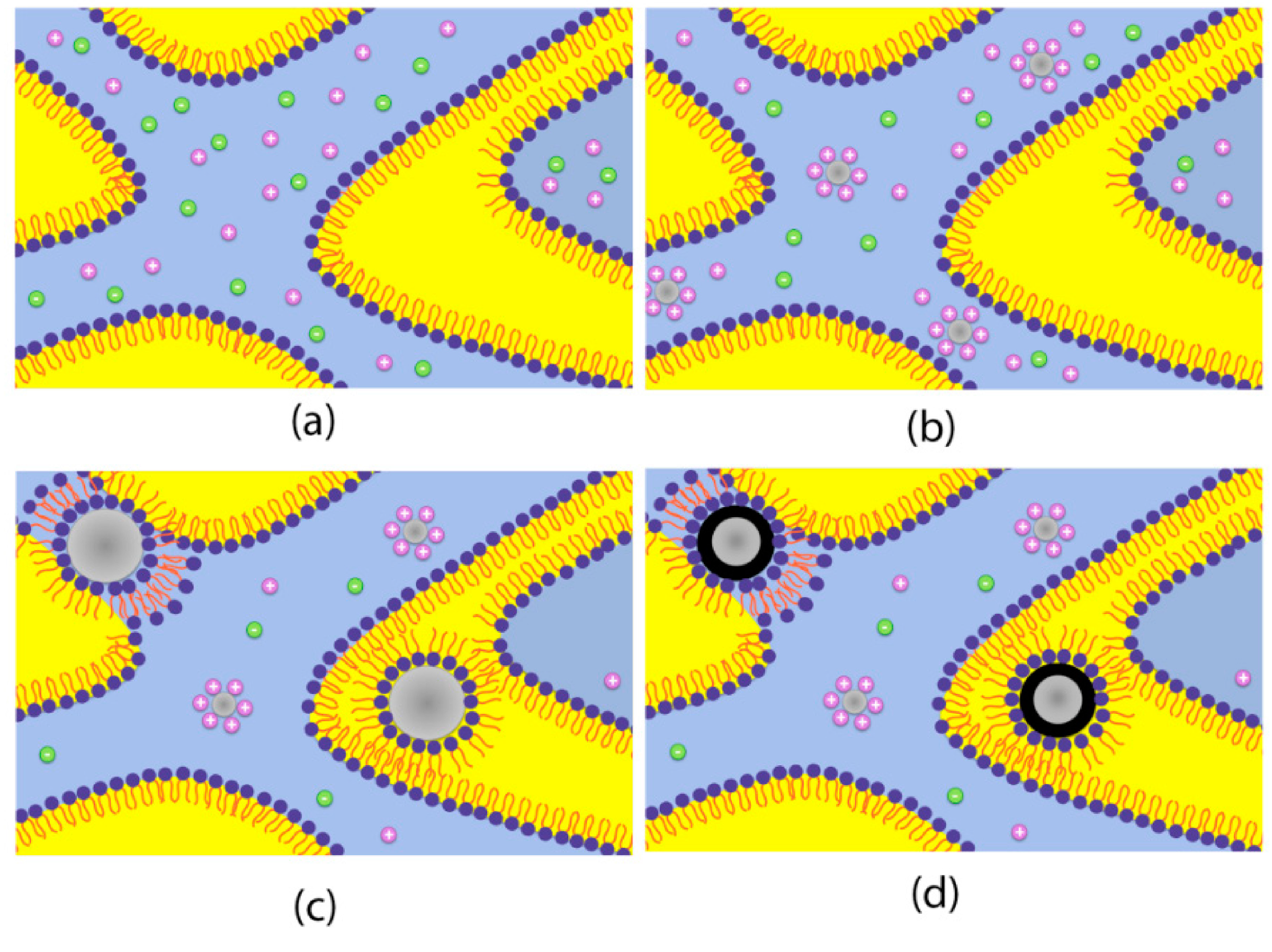
For the synthesis of core-shell particles in bicontinuous microemulsion the procedure described in [26] was adapted with a final, galvanic displacement step after synthesizing iron core nanoparticles, see Figure 3. The deposition of the shell material (Pt) was carried out by adding one microemulsion containing Pt-salt without further addition of reducing agent. In a subsequent step the synthesized core-shell particles were brought on a high surface area carbon support (VulcanXC72, Cabot, Boston,, MA, USA) and washed thoroughly with water, tetrahydrofuran and acetone. As a last step in the washing procedure the particles were washed with 0.25 M HCl and again water.
Figure 3.
Schematic picture of core particle formation (a)–(c) and subsequent galvanic displacement to form final core-shell particles (d). Graphics adapted with permission from [26], 2014, American Chemical Society.
Figure 3.
Schematic picture of core particle formation (a)–(c) and subsequent galvanic displacement to form final core-shell particles (d). Graphics adapted with permission from [26], 2014, American Chemical Society.

5. Conclusions
No synthesis technique so far possesses the ability to accurately control the (geometrical) properties of core-shell particles. Considering the fine balance between achieving a core-shell structure and ending up with unwanted structures, it is evident that a core-shell structure cannot be presumed but needs to be thoroughly investigated. The success of such an investigation depends heavily on the individual instrument quality and on how the available techniques are combined. However, there is no exclusive or general approach to determining core-shell structures.
Any surfactant molecules remaining on the surface on particles made in microemulsion will affect the characterization results and may ultimately hamper the catalytic activity for the particles. Surfactant molecules with high affinity for the particle surface are desired to prevent particles from agglomeration but on the other hand they must be removable without causing the final catalyst particles to sinter.
Proving a shell that is pinhole free cannot be done with any spectroscopic technique alone. Complementary electrochemical measurements are crucial in order to get an estimate of the shell porosity. A key feature is the composition of the outermost surface layer—not the least since catalyst particles are intrinsically surface active materials. Although rare, high quality techniques such as microscopes or spectroscopies with capabilities beyond nanometer scale are now emerging and becoming available, eventually opening up the possibility to determine even mono-atomic shell layers. Finally, taking into account the need for high-end instruments, extensive collaboration would benefit the general success in determining the nature of core-shell structured particles.
Acknowledgments
This work was financially supported by NanoNextNL, a micro and nanotechnology programme of the Dutch Government and 130 partners and by the COST CM1101 Action.
Author Contributions
E.E. Westsson did the preparational work and wrote the paper; G.J.M. Koper supervised.
Conflicts of Interest
The authors declare no conflict of interest.
References
- Maillard, F.; Pronkin, S.; Savinova, E.R. Size effects in electrocatalysis of fuel cell reactions on supported metal nanoparticles. 2009. [Google Scholar] [CrossRef]
- Hosokawa, M. Nanoparticle Technology Handbook; Elsevier: Amsterdam, The Netherland, 2007. [Google Scholar]
- Eftekhari, A. Nanostructured Materials in Electrochemistry; Wiley: Manhattan, NY, USA, 2008. [Google Scholar]
- Barcari, G. Metal. Nanoparticles and Nanoalloys; Wilcoxon, J., Johnston, R.L., Eds.; Elsevier: Amsterdam, The Netherland, 2012; pp. 213–247. [Google Scholar]
- Kitchin, J.; Nørskov, J.; Barteau, M.; Chen, J. Role of Strain and Ligand Effects in the Modification of the Electronic and Chemical Properties of Bimetallic Surfaces. Phys. Rev. Lett. 2004, 93. [Google Scholar] [CrossRef] [PubMed]
- Oezaslan, M.; Hasché, F.; Strasser, P. Pt.-Based Core–Shell Catalyst Architectures for Oxygen Fuel Cell Electrodes. J. Phys. Chem. Lett. 2013, 4, 3273–3291. [Google Scholar] [CrossRef]
- Roller, J.; Yu, H.; Vukmirovic, M.; Bliznakov, S.; Kotula, P.; Carter, C.; Adzic, R.; Maric, R. Flame-Based Synthesis of Core-Shell Structures Using Pd-Ru and Pd Cores. Electrochim. Acta 2014, 138, 341–352. [Google Scholar] [CrossRef]
- Hammer, B.M.; Morikawa, Y.; Norskov, J.K. CO Chemisorption at Metal. Surfaces and Overlayers. Phys. Rev. Lett. 1996, 76. [Google Scholar] [CrossRef]
- Holmblad, P.M.L.; Larsen, J.H.; Chorkendorff, I.; Nielsen, L.P.; Besenbacher, F.S.I.; Laegsgaard, E.; Kratzer, P.; Hammer, B.N.; NØrskov, J.K. Designing surface alloys with specific active sites. Catal. Lett. 1996, 40, 131–135. [Google Scholar] [CrossRef]
- Teng, X.; Yang, H. Synthesis of magnetic nanocomposites and alloys from platinum-iron oxide core-shell nanoparticles. Nanotechnology 2005, 16, S554–S561. [Google Scholar] [CrossRef] [PubMed]
- Yu, Y.-T.; Dutta, P. Synthesis of Au/SnO2 core–shell structure nanoparticles by a microwave-assisted method and their optical properties. J. Solid State 2011, 184, 312–316. [Google Scholar] [CrossRef]
- Liu, Y.T.; Yuan, Q.B.; Duan, D.H.; Zhang, Z.L.; Hao, X.G.; Wei, G.Q.; Liu, S.B. Electrochemical activity and stability of core–shell Fe2O3/Pt nanoparticles for methanol oxidation. J. Power Sources 2013, 243, 622–629. [Google Scholar] [CrossRef]
- Geboes, B.; Mintsouli, I.; Wouters, B.; Georgieva, J.; Kakaroglou, A.; Sotiropoulos, S.; Valova, E.; Armyanov, S.; Hubin, A.; Breugelmans, T. Surface and Electrochemical Characterisation of a Pt-Cu/C Nano-structured Electrocatalyst, Prepared by Galvanic Displacement. Appl. Catal. B 2013. [Google Scholar] [CrossRef]
- Xia, L.; Hua, X.; Kanga, X.; Zhao, H.; Sunb, M.; Cihen, X. A one-step facile synthesis of Ag–Ni core–shell nanoparticles in water-in-oil microemulsions. Colloids Surf. 2010, 367, 96–101. [Google Scholar] [CrossRef]
- Balerna, A.; Evangelisti, C.; Schiavi, E.; Vitulli, G.; Bertinetti, L.; Martra, G.; Mobilio, S. EXAFS and XANES structural characterization of bimetallic AuPd vapor derived catalysts. J. Phys. 2013, 430. [Google Scholar] [CrossRef]
- Wang, C.; Wang, G.; van der Vliet, D.; Chang, K.C.; Markovic, N.M.; Stamenkovic, V.R. Monodisperse Pt(3)Co nanoparticles as electrocatalyst: the effects of particle size and pretreatment on electrocatalytic reduction of oxygen. Phys. Chem. Chem. Phys. 2010, 12, 6933–6939. [Google Scholar] [CrossRef] [PubMed]
- Zhang, J.; Lima, F.H.B.; Shao, M.H.; Sasaki, K.; Wang, J.X.; Hanson, J.; Adzic, R.R. Platinum monolayer on nonnoble metal-noble metal core-shell nanoparticle electrocatalysts for O2 reduction. J. Phys. Chem. B 2005, 109, 22701–22704. [Google Scholar] [CrossRef] [PubMed]
- Mayrhofer, K.J.; Juhart, V.; Hartl, K.; Hanzlik, M.; Arenz, M. Adsorbate-induced surface segregation for core-shell nanocatalysts. Angew. Chem. Int. Ed. 2009, 48, 3529–3531. [Google Scholar] [CrossRef]
- Zhang, Y.; Ma, C.; Zhu, Y.; Si, R.; Cai, Y.; Wang, J.X.; Adzic, R.R. Hollow core supported Pt monolayer catalysts for oxygen reduction. Catal. Today 2013, 202, 50–54. [Google Scholar] [CrossRef]
- Pigozzi, G.; Mukherji, D.; Elerman, Y.; Strunz, P.; Gilles, R.; Hoelzel, M.; Barbier, B.; Schmutz, P. Effects of size reduction on the structure and magnetic properties of core–shell Ni3Si/silica nanoparticles prepared by electrochemical synthesis. J. Alloys Compd. 2014, 584, 119–127. [Google Scholar] [CrossRef]
- Yang, Y.; Shi, J.; Kawamura, G.; Nogami, M. Preparation of Au–Ag, Ag–Au core–shell bimetallic nanoparticles for surface-enhanced Raman scattering. Scripta Mater. 2008, 58, 862–865. [Google Scholar] [CrossRef]
- Steinbrück, A.; Csáki, A.; Festag, G.; Fritzsche, W. Preparation and Optical Characterization of Core–Shell Bimetal Nanoparticles. Plasmonics 2006, 1, 79–85. [Google Scholar] [CrossRef]
- Kumar, S.; Zou, S. Electrooxidation of Carbon Monoxide and Methanol on Platinum-Overlayer-Coated Gold Nanoparticles: Effects of Film Thickness. Langmuir 2007, 23, 7365–7371. [Google Scholar] [CrossRef] [PubMed]
- Kuttiyiel, K.A.; Sasaki, K.; Su, D.; Vukmirovic, M.B.; Marinkovic, N.S.; Adzic, R.R. Pt monolayer on Au-stabilized PdNi core–shell nanoparticles for oxygen reduction reaction. Electrochim. Acta 2013, 110, 267–272. [Google Scholar] [CrossRef]
- Najjar, R. Microemulsions—An Introduction to Properties and Applications; InTech Publisher: Rijeka, Croatia, 2012. [Google Scholar]
- Negro, E.; Latsuzbaia, R.; Koper, G.J. Bicontinuous microemulsions for high yield wet synthesis of ultrafine platinum nanoparticles: Effect of precursors and kinetics. Langmuir 2014, 30, 8300–8307. [Google Scholar] [CrossRef] [PubMed]
- Sieben, J.M.; Comignani, V.; Alvarez, A.E.; Duarte, M.M. Synthesis and characterization of Cu core Pt–Ru shell nanoparticles for the electro-oxidation of alcohols. Int. J. Hydrogen Energ. 2014, 39, 8667–8674. [Google Scholar] [CrossRef]
- Tsai, C.W.; Chen, H.M.; Liu, R.S.; Lee, J.F.; Chang, S.M.; Weng, B.J. Magnetically recyclable Fe@Co core-shell catalysts for dehydrogenation of sodium borohydride in fuel cells. Int. J. Hydrogen Energ. 2012, 37, 3338–3343. [Google Scholar] [CrossRef]
- Wojtysiak, S.; Solla-Gullón, J.; Dłużewski, P.; Kudelski, A. Synthesis of core–shell silver–platinum nanoparticles, improving shell integrity. Colloids Surf. A 2014, 441, 178–183. [Google Scholar] [CrossRef]
- Chen, D.; Liu, S.; Li, J.; Zhao, N.; Shi, C.; Du, X.; Sheng, J. Nanometre Ni and core/shell Ni/Au nanoparticles with controllable dimensions synthesized in reverse microemulsion. J. Alloys Compd. 2009, 475, 494–500. [Google Scholar] [CrossRef]
- Tojo, C.; Dios, M.; Barroso, F. Surfactant Effects on Microemulsion-Based. Nanoparticle Synthesis. Materials 2010, 4, 55–72. [Google Scholar]
- Lee, J.P.; Chen, D.; Li, X.; Yoo, S.; Bottomley, L.A.; El-Sayed, M.A.; Park, S.; Liu, M. Well-organized raspberry-like Ag@Cu bimetal nanoparticles for highly reliable and reproducible surface-enhanced Raman scattering. Nanoscale 2013, 5, 11620–11624. [Google Scholar] [CrossRef] [PubMed] [Green Version]
- Li, C.; Yamauchi, Y. Facile solution synthesis of Ag@Pt core-shell nanoparticles with dendritic Pt shells. Phys. Chem. Chem. Phys. 2013, 15, 3490–3496. [Google Scholar] [CrossRef] [PubMed]
- Merzlikin, S. Depth Profiling by X-ray Photoelectron Spectroscopy. In Fakultät für Chemie; Ruhr-Universität Bochum: Bochum, Germany, 2007. [Google Scholar]
- Mendis, B.G.; Craven, A.J. Characterising the surface and interior chemistry of core-shell nanoparticles using scanning transmission electron microscopy. Ultramicroscopy 2011, 111, 212–226. [Google Scholar] [CrossRef] [PubMed]
- Li, Z. Scanning Transmission Electron Microscopy Studies of Mono- and Bimetallic. Nanoclusters 2012, 3, 213–247. [Google Scholar]
- Vogt, T.; Dahmen, W.; Binev, P. Modeling Nanoscale Imaging in Electron; Springer: Manhattan, NY, USA, 2012. [Google Scholar]
- Zhou, W.; Wang, Z.L. Scanning Microscopy for Nanotechnology; Springer: Manhattan, NY, USA, 2007. [Google Scholar]
- Tilinin, I.S. Qualitative Surface Analysis by Auger and X-Ray Photoelectron Spectroscopy. Available online: http://www.surfaceanalysis.org/BriggsGrant.html (accessed on 19 November 2014).
- Egerton, R.F. Electron Energy-Loss Spectroscopy. In Electron Microscope; Springer: Manhattan, NY, USA, 2011. [Google Scholar]
- Liu, J.; Hembree, G.G.; Spinnler, G.E.; Venables, J.A. High-Resolution Auger-Electron Spectroscopy and Microscopy of a Supported Metal Catalyst. Surf. Sci. 1992, 262, L111–L117. [Google Scholar] [CrossRef]
- Lukasczyk, T. Generation of Pure Iron Nanostructures via Electron-beam Induced Deposition in UHV. In Der Naturwissenschaftlichen Fakultät; Friedrich-Alexander-Universität: Erlangen-Nürnberg, Germany, 2010. [Google Scholar]
- Camardese, J.; McCalla, E.; Abarbanel, D.W.; Dahn, J.R. Determination of Shell Thickness of Spherical Core-Shell NixMn1-x(OH)2 Particles via Absorption Calculations of X-ray Diffraction Patterns. J. Electrochem. Soc. 2014, 161, A814–A820. [Google Scholar] [CrossRef]
- Zolotoyabko, E. Basic Concepts of X-ray Diffraction; Wiley: Manhattan, NY, USA, 2014. [Google Scholar]
- Merzlikin, S.V.; Tolkachev, N.N.; Strunskus, T.; Witte, G.; Glogowski, T.; Wöll, C.; Grünert, W. Resolving the depth coordinate in photoelectron spectroscopy—Comparison of excitation energy variation vs. angular-resolved XPS for the analysis of a self-assembled monolayer model system. Surf. Sci. 2008, 602, 755–767. [Google Scholar]
- Silva, D.O.; Luza, L.; Gual, A.; Daniel, B.L.; Bernardi, F.; Zapata, M.J.; Dupont, J. Straightforward synthesis of bimetallic Co/Pt nanoparticles in ionic liquid: Atomic rearrangement driven by reduction-sulfidation processes and Fischer-Tropsch catalysis. Nanoscale 2014, 6, 9085–9092. [Google Scholar] [CrossRef] [PubMed]
- Prabhuram, J.; Wang, X.; Hui, C.L.; Hsing, I.M. Synthesis and Characterization of Surfactant-Stabilized Pt/C Nanocatalysts for Fuel Cell Applications. J. Phys. Chem. B 2003, 107, 11057–11064. [Google Scholar] [CrossRef]
- Kendick, I.; Smotkin, E.S. Infrared and X-ray Absorption Spectroscopy of Operating Fuel Cells. Available online: http://nuvant.com/pdfs/Kendrick%20PCCP_Review_cut.pdf (accessed on 19 November 2014).
- Russell, A.E.; Rose, A. X-ray absorption spectroscopy of low temperature fuel cell catalysts. Chem. Rev. 2004, 104, 4613–4635. [Google Scholar] [CrossRef] [PubMed]
- Liu, Z.; Hu, J.E.; Wang, Q.; Gaskell, K.; Frenkel, A.I.; Jackson, G.S.; Eichhorn, B. PtMo Alloy and MoOx@Pt Core-Shell Nanoparticles as Highly CO-Tolerant Electrocatalysts. J. Am. Chem. Soc. 2009, 131, 6924–6925. [Google Scholar] [CrossRef] [PubMed]
- Alayoglu, S.; Zavalij, P.; Eichhorn, B.; Wang, Q.; Frenkel, A.I.; Chupas, P. Structural and Architectural Evaluation of Bimetallic Nanoparticles: A Case Study of PtRu Core-Shell and Alloy Nanoparticles. ACS Nano 2009, 3, 3127–3137. [Google Scholar] [CrossRef] [PubMed]
- Ochal, P.; de la Fuente, J.; Tsypkin, M.; Seland, F.; Sunde, S.; Muthuswamy, N.; Rønning, M.; Chen, D.; Garcia, S.; Alayoglu, S.; et al. CO stripping as an electrochemical tool for characterization of Ru@Pt core-shell catalysts. J. Electroanal. Chem. 2011, 655, 140–146. [Google Scholar] [CrossRef]
- Cookson, N.J. Preparation and Characterisation of Bimetallic Core-Shell Particles. Master Thesis, University of Birmingham, Birmingham, UK, September 2009. [Google Scholar]
- Henglein, A. Preparation and Optical Aborption Spectra of AucorePtshell and PtcoreAushell Colloidal Nanoparticles in Aqueous Solution. J. Phys. Chem. B 2000, 104, 2201–2203. [Google Scholar] [CrossRef]
- Creighton, J.A.; Eadon, D.G. Ultraviolet Visible Absorption-Spectra of the Colloidal Metallic Elements. J. Chem. Soc. 1991, 87, 3881–3891. [Google Scholar]
- Rao, A.; Schoenenberger, M.; Gnecco, E.; Glatzel, T.; Meyer, E.; Brändlin, D.; Scandella, L. Characterization of nanoparticles using Atomic Force Microscopy. J. Phys. 2007, 61, 971–976. [Google Scholar]
- Newton, J.E.; Preece, J.A.; Rees, N.V.; Horswell, S.L. Nanoparticle catalysts for proton exchange membrane fuel cells: Can surfactant effects be beneficial for electrocatalysis? Phys. Chem. Chem. Phys. 2014, 16, 11435–11446. [Google Scholar] [CrossRef] [PubMed]
- Crespo, P.; Litrán, R.; Rojas, T.C.; Multigner, M.; De la Fuente, J.M.; Sánchez-López, J.C.; Garcia, M.A.; Hernando, A.; Penadés, S.; Fernández, A. Permanent Magnetism, Magnetic Anisotropy, and Hysteresis of Thiol-Capped Gold Nanoparticles. Phys. Rev. Lett. 2004, 93. [Google Scholar] [CrossRef] [PubMed]
- Vesperinas, A.; Eastoe, J.; Jackson, S.; Wyatt, P. Light-induced flocculation of gold nanoparticles. Chem. Commun. 2007, 38, 3912–3914. [Google Scholar] [CrossRef]
- Eastoe, J. Photo-destructible Surfactants in Microemulsions. In Progress in Colloid and Polymer Science; Springer: Berlin, Germany, 2006; Volume 133, pp. 106–110. [Google Scholar]
- Lim, J.; Yeap, S.P.; Che, H.X.; Low, S.C. Characterization of magnetic nanoparticle by dynamic light scattering. Nanoscale Res. Lett. 2013, 8. [Google Scholar] [CrossRef]
- Pecora, R. Dynamic Light Acattering; Plenum Press: New York, NY, USA, 1985. [Google Scholar]
- Goldstein, J. Scanning Electron Microscopy and X-ray Microanalysis; Springer: Manhattan, NY, USA, 2003. [Google Scholar]
- Crewe, A.V. The use of backscattered electrons for imaging purposes in a scanning electron microscope. Ultramicroscopy 1976, 1, 231–238. [Google Scholar] [CrossRef] [PubMed]
- Carter, H.W. Backscattered Electron Imaging: Theory and Applications. Micron 1980, 11, 259–260. [Google Scholar]
- Vogt, T.; Dahmen, W.; Binev, P. Modeling Nanoscale Imaging in Electron; Springer: Manhattan, NY, USA, 2012. [Google Scholar]
- Tanuma, S.; Powell, C.J.; Penn, D.R. Calculations of electron inelastic mean free paths. IX. Data for 41 elemental solids over the 50 eV to 30 keV range. Surf. Interface Anal. 2011, 43, 689–713. [Google Scholar] [CrossRef]
- Hergert, W.; Wriedt, T. The Mie Theory; Springer: Manhattan, NY, USA, 2012; Volume 169. [Google Scholar]
- Eccles, J.W.L.; Bangert, U.; Bromfield, M.; Christian, P.; Harvey, A.J.; Thomas, P. UV-Vis. plasmon studies of metal nanoparticles. J. Phys. 2010, 241. [Google Scholar] [CrossRef]
- Pletcher, D. Instrumental Methods in Electrochemistry; Horwood Publishing: Cambridge, UK, 2001. [Google Scholar]
© 2014 by the authors; licensee MDPI, Basel, Switzerland. This article is an open access article distributed under the terms and conditions of the Creative Commons Attribution license (http://creativecommons.org/licenses/by/4.0/).
Share and Cite
MDPI and ACS Style
Westsson, E.; Koper, G.J.M. How to Determine the Core-Shell Nature in Bimetallic Catalyst Particles? Catalysts 2014, 4, 375-396. https://doi.org/10.3390/catal4040375
AMA Style
Westsson E, Koper GJM. How to Determine the Core-Shell Nature in Bimetallic Catalyst Particles? Catalysts. 2014; 4(4):375-396. https://doi.org/10.3390/catal4040375
Chicago/Turabian StyleWestsson, Emma, and Ger J.M. Koper. 2014. "How to Determine the Core-Shell Nature in Bimetallic Catalyst Particles?" Catalysts 4, no. 4: 375-396. https://doi.org/10.3390/catal4040375