On-Chip Asymmetric Microsupercapacitors Combining Reduced Graphene Oxide and Manganese Oxide for High Energy-Power Tradeoff

1
Department of Mechanical and Materials Engineering, Florida International University, Miami, FL 33174, USA
2
Center for the Study of Matter of Extreme Conditions (CeSMEC), Florida International University, Miami, FL 33199, USA
*
Author to whom correspondence should be addressed.
Micromachines 2018, 9(8), 399; https://doi.org/10.3390/mi9080399
Submission received: 12 July 2018
/
Revised: 7 August 2018
/
Accepted: 10 August 2018
/
Published: 12 August 2018
(This article belongs to the Special Issue Atomic Scale Materials for Electronic and Photonic Devices)
Abstract
:Given the rapid miniaturization of technology, it is of interest to produce viable on-chip micro-electrochemical energy storage systems. In this study, interdigitated asymmetric microsupercapacitors were fabricated using photolithography, lift-off and electrodeposition methods. Manganese oxide (MnOx) and reduced graphene oxide (rGO) comprised the pseudocapacitive and the double layer component, respectively. Symmetric MnOx//MnOx, rGO//rGO as well as asymmetric rGO//MnOx microsupercapacitors with three different MnOx thicknesses were constructed and characterized in aqueous media. The asymmetric microsupercapacitor with the intermediate MnOx film thickness displayed the optimal energy-power trade-off superior to that of both the symmetric and well as the other asymmetric configurations. The optimal microsupercapacitor exhibited a high stack energy density of 1.02 mWh·cm−3 and a maximal power density of 3.44 W·cm−3. The high energy-power trade-off of the device is attributed to the synergistic effects of utilizing double layer and pseudocapacitive charge storage mechanisms along with in-plane interdigital microelectrode design within one optimized micro-device.
1. Introduction
With the technological impetus of going “micro”, it is imperative to create small-scale energy devices that can effectively power such miniaturized devices. Given the existing myriad of minuscule systems such as implantable medical devices (IMDs), wireless sensors, smart cards, personal electronics, etc. that typically require power in the range of several µW to several hundred mW, it is essential to shrink the sizes of the energy storage components further. Currently, the majority of the micro-devices rely on batteries to provide the required energy and power. However the relatively poor power-handling ability and limited lifetime of batteries hinder their applicability to systems that require high current spikes [1]. As an alternative to batteries, energy harvesters hold significant promise for sustainable environments; however, the currently existing energy harvester systems require an energy storage device in tandem [1]. Electrochemical capacitors, also known as supercapacitors (SCs), on the other hand, can provide high powers along with long cycle lives. Based on the charge storage mechanisms, SCs can be divided into two major categories—electrochemical double layer capacitors (EDLCs) and redox or “pseudocapacitors”. The former rely on the adsorption of ions at the electrode/electrolyte interface and typically comprise different forms of carbons, whereas the latter store charges in a faradaic/redox manner with fast and reversible redox reactions and encompass different transition metal oxides (TMOs) and conjugated polymers [2]. Typically, pseudocapacitive materials exhibit larger specific capacitances, whereas double layer type materials exhibit better rate handling capability and superior cycle longevity [2].
Quite akin to their larger variants, miniaturized electrochemical energy storage (EES) systems can be connected externally for peak power and energy delivery; nevertheless, it is desirable for the next generation micro-power devices to be single standalone systems that can provide with simultaneous supply of high energy and high power. One of the strategies for achieving the latter is the asymmetric or hybrid supercapacitor design. Such systems typically combine a redox-type electrode along with a counter double layer capacitive electrode in one cohesive system and benefit from the larger capacity of the redox material and the superior kinetics and cycle life of the double layer material. Several asymmetric systems have been reported in the literature including pseudocapacitive metal oxides such as ruthenium oxide (RuO2) [3], manganese oxide (MnOx) [4,5,6,7,8], nickel oxide (NiOx) [9,10], as well as lithium insertion materials (lithium-ion capacitors) including pre-lithiated carbons [11,12,13], lithium titanate (Li4Ti5O12) [14,15,16,17], and lithium iron phosphate (LiFePO4) [18,19] coupled with different carbons. While the asymmetric design offers significant promise from materials perspective, the “in-plane interdigital design” offers a multitude of advantages from an architectural standpoint. For instance, having alternating digits of anode and cathode materials in close proximity can shorten the ion-transport pathways and can effectively enhance the rate capability of the on-chip systems. As opposed to the conventional two-dimensional (2D) thin-film design, the interdigital architecture allows for larger accessibility of the electrodes as the sides of the microelectrodes are exposed to the electrolyte [1]. The enhanced accessibility of the electrodes is especially well-suited for layered 2D materials, where the electrolyte ions can have facile access between the layers of the material by having the electrodes side-by-side [1].
One of the widely investigated 2D layered materials is graphene, which is essentially a one-atom thick sp2 hybridized carbon sheet [2]. Owing to its high theoretical specific surface area (~2600 m2/g), exceptional electronic conductivity, and superior mechanical strength, graphene has been extensively explored as an EDLC material [2,20,21,22]. Despite the phenomenal properties of graphene, it is, however, challenging to fully realize the theoretical values, given the high degree of graphene sheet restacking [2,12]. Furthermore, the hydrophobic nature of graphene makes it challenging to effectively disperse it in solvents. One of the derivatives of graphene is graphene oxide (GO), which in essence is graphene decorated with oxygen-containing groups on both the basal planes and the edges [23,24]. The oxygen functionality makes GO hydrophilic, which can assist in its effective dispersion in solvents as well as enhance the interaction with the electrolyte [25]. However, the oxygenated groups make GO insulating and for SC applications, effective reduction of GO is desired in order to utilize the electronic properties of graphene. Typically, GO is reduced to reduced graphene oxide (rGO) using strong reducing agents like hydrazine, which could be both cost-prohibitive and damaging to the environment [25]. As an alternative to chemical reduction, electrophoretic deposition (EPD) offers the possibility to effectively reduce GO without the need for any additional reducing agents [26]; An et al. [27] noted that the rGO films synthesized via EPD exhibited much superior electrical conductivity over the parent GO papers (1.43 × 10⁴ S·m−1 as opposed to 0.53 × 10⁻³ S·m−1). EPD is a thin-film synthesis method, which essentially involves the movement of charged particles in a colloidal suspension under the influence of an electric field [26,28]. Given the feasibility to simultaneously integrate and reduce GO using EPD, the latter method was utilized to fabricate the rGO microelectrodes for the microsupercapacitors (MSCs) for this work.
As pseudocapacitive or redox materials, manganese oxides (MnOx), in all polymorphs, have been widely studied owing to their high theoretical specific capacitance, environmental benignity, large abundance and low cost [29,30,31,32]. Different asymmetric configurations utilizing MnOx have been investigated for MSC applications including activated carbons (AC) [33], carbon nanotubes (CNT) [34], laser scribed graphene (LSG) [35], as well as graphene quantum dot (GQD) [36] counter electrodes. In this work, MnOx was electrochemically deposited onto gold micro-current collectors as the cathode component of the asymmetric MSCs against the electrophoretically prepared rGO counter microelectrode. The optimized asymmetric rGO//MnOx MSC was able to deliver areal capacitances as high as 1.63 mF·cm−2, equivalent to a stack/volumetric capacitance of 3.6 F·cm−3 as well as volumetric energy and power densities of 1.02 mWh·cm−3 and 3441 mW·cm−3, much superior to those of both the symmetric MnOx//MnOx and rGO//rGO systems. The excellent energy-power tradeoff and high specific capacitance of the asymmetric capacitor is attributed to the synergy between the pseudocapacitive MnOx component and the double layer rGO component in addition to the in-plane interdigital microelectrode design.
2. Materials and Methods
2.1. Fabrication of the Interdigital Gold Micro-Current Collectors
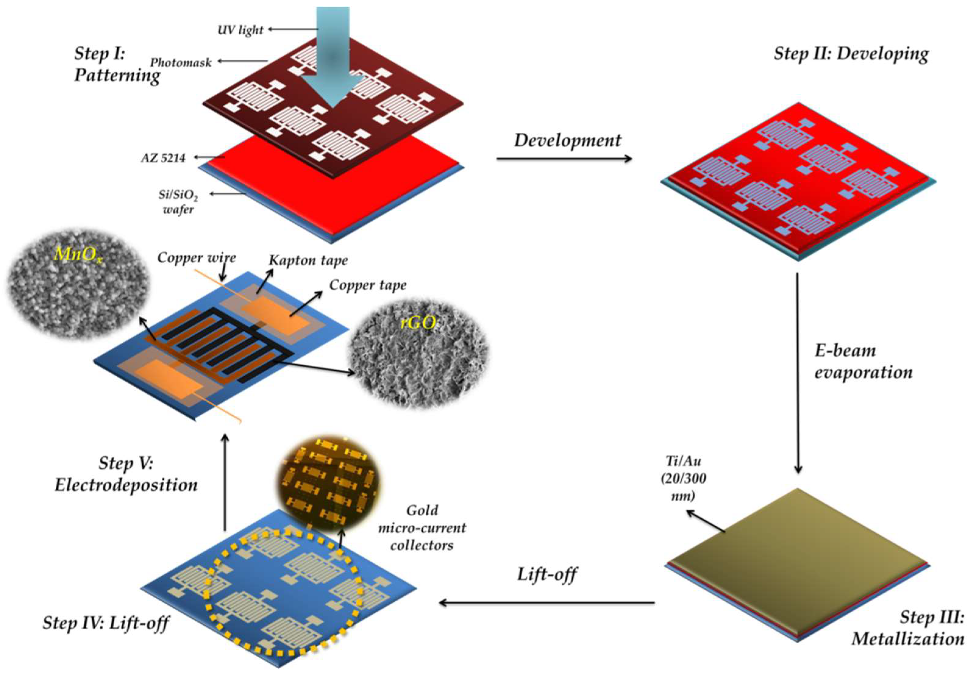
To construct the interdigital gold micro-current collectors, conventional photolithography and lift-off methods were used. A schematic illustration has been shown in Figure 1 (Step I-Step IV). First, AZ 5214 (Microchemicals, Ulm, Germany), a positive-tone photoresist, was spun-coated on a 4” Si/SiO2 (100) wafer at a speed of 5000 rpm for 30 s. After the spin coating process, a soft bake was carried out for 1 min at a temperature of 110 °C on a leveled hot plate. After the bake process, ultraviolet exposure was carried out using an OAI mask aligner with a UV dose of 230 mJ·cm−2. Following the expose step, a develop step was carried out using AZ 300 MIF (Integrated Micro Materials, Argyle, TX, USA) for ~45 s. After the develop step, a de-scum step was carried out using an O2 plasma at a flow rate of 60 sccm and a pressure of 400 mTorr for 30 s using reactive ion etching (RIE). Following the patterning of the photoresist, metallization process (Ti/Au (20/300 nm)) was carried out using e-beam evaporation with a CHA evaporator (CHA Industries, Inc., Fremont, CA, USA). After the metallization process, lift-off was carried out in order to get rid of sacrificial photoresist using acetone and mechanical agitation, followed with isopropyl alcohol rinsing and N2 drying. Finally, a 30 s O2 plasma treatment at 400 mTorr was carried out in order to get rid of any organic residues. The typical width of the gold fingers was 100 µm with an interdigital gap of 100 µm and a length of 8800 μm. Each electrode comprised 18 fingers, resulting in a total of 36 fingers for a single device and a total finger area of 0.3168 cm2, whereas the effective footprint area of the device (including finger gaps) was ~0.66 cm2. Unless otherwise mentioned, the electrochemical parameters were normalized with the finger area in this work.
2.2. Active Material Integration
After constructing the gold micro-current collectors, the active materials (rGO and MnOx) were integrated onto the current collectors using electrodeposition (electrochemical and electrophoretic deposition methods). For the symmetric MnOx//MnOx microsupercapacitor, a three-electrode setup was used where the interdigitated gold current collectors functioned as the working electrode, and an Ag/AgCl electrode (and a platinum coil functioned as the reference and counter electrode, respectively). An anodic current of 0.5 mA·cm−2 was applied for 20 min (equivalent to an applied charge of 0.6 C·cm−2) in an electrolyte solution containing 0.2M manganese acetate (Sigma-Aldrich, St. Louis, MO, USA) and 0.2 M Na2SO4 (Sigma-Aldrich, St. Louis, MO, USA). After the deposition process, the electrodes were washed with deionized (DI) water and dried overnight before being used for further characterization. For the rGO deposition for the symmetric rGO//rGO microsupercapacitor, a suspension containing single layer graphene oxide (SLGO, Cheap Tubes Inc., Cambridgeport, VT, USA) and C2H5OH:DI water (90:10, v:v) in a concentration of 1 mg·mL−1 was used for the EPD process after 1 h ultrasonication. An electric field of ~40 V cm−1 was applied between the gold current collectors (working electrode) and a platinum coil (counter electrode); small amounts of MgCl2 (0.1 mg·mL−1) were added to the GO solution in order to enhance the conductivity and facilitate the EPD process. For the asymmetric microsupercapacitors (schematic illustration shown in Figure 1 Step V), three different depositions of manganese oxide comprising anodic charges of 0.6, 0.9 and 1.2 C·cm−2 were evaluated against a 5 min deposition of rGO. rGO was deposited first on one of the interdigital electrodes as described earlier, followed by the respective MnOx deposition on the counter electrode. The device was washed several times with DI water and dried thoroughly prior to its characterization.
2.3. Material Characterization
X-ray diffraction (XRD) studies on the electrochemically deposited MnOx were carried out using a Siemens D5000 Diffractometer (Siemens, Munich, Germany) with Cu-Kα radiation. For spectroscopic characterization on the electrochemically deposited MnOx and the electrophoretically rGO films, Fourier Transform Infrared (FTIR) studies were carried out using a JASCO FTIR-4100 (JASCO, Easton, MD, USA) equipped with an attenuated total reflectance (ATR) accessory The top and the cross sectional views of the symmetric and asymmetric microsupercapacitors were investigated using scanning electron microscopy (SEM) with a JEOL SEM 6330 (JEOL, Peabody, MA, USA) in the secondary electron imaging (SEI) mode.
2.4. Electrochemical Characterization
The electrochemical characterization on the symmetric rGO//rGO, MnOx//MnOx, as well as the asymmetric rGO//MnOx microsupercapacitors was carried out in an aqueous electrolyte containing 1 M Na2SO4 using a Bio-logic Versatile Multichannel Potentiostat (VMP3) (Bio-Logic, Seyssinet-Pariset, France). Two-electrode studies were carried out for both the symmetric and asymmetric configurations and all the experiments were carried out at room temperature, in a sealed beaker-type cell assembly. All the electrochemical parameters were normalized with the total finger/active material area and the systems were evaluated using cyclic voltammetry (CV), galvanostatic charging and discharging (GCD), as well as electrochemical impedance spectroscopy (EIS) measurements.
3. Results
3.1. Spectroscopic, Crystallographic and Microstructural Characterization Performed on the Manganese Oxide and rGO Microelectrodes
The FTIR spectra of the starting GO powders and the EPD reduced GO (rGO) is shown in Figure 2a. The broad absorption peak centered around 3374 cm−1 in the GO powder is the characteristic infrared (IR) band position from the OH stretching vibrations [37,38], whereas the peaks at 1727, 1624, 1377, 1234, and 1083 cm−1 are attributed to C=O stretching [38], aromatic C=C stretching [39], carboxyl [40], epoxide C-O-C or phenolic C-O-H stretching vibrations [40], C-O stretching in epoxy or alkoxy groups [40], respectively. It is worth noting that the intensity from the hydroxyl groups is substantially mitigated in the EPD-based rGO film, indicating effective reduction of GO during electrophoresis. Furthermore, the intensity of the other functional groups signaling the presence of oxygen was reduced; the peak at 1615 cm−1 was however quite prevalent in the rGO spectrum, signaling the presence of aromatic C=C stretching [39], which is from the parental graphitic skeleton.
The FTIR spectrum of the electrodeposited MnOx is shown in Figure 2b; the peaks located around 510, 526, and 585 cm−1 (below 750 cm−1, shown as the inset) are ascribed to the Mn-O vibrations from the MnO6 octahedra and are consistent with previous reports [41,42]. The XRD pattern of the electrochemically deposited manganese oxide films is shown in Figure 2c. The material is of low degree of crystallinity; however the faint peaks present in the diffraction pattern are ascribed to α-MnO2 (JCPDS Card Number: 00-044-0141). The peaks at 18.1°, 28.8°, 37.5°, 46.1°, 56.9°, and 65.2° are indexed as (hkl) plane orientations of (200), (310), (211), (321), (431), and (002), respectively of α-MnO2 phase. However, owing to the poor degree of crystallinity the manganese oxide is referred to as MnOx.
The top view of the asymmetric interdigitated MSC is shown in Figure 3a. Figure 3b displays the cross-sectional view of the rGO electrode—the structure consisted of graphene layers as expected from the parent graphene oxide powders (SEM micrograph shown in Supplementary file Figure S1) and the rGO film had an average thickness of ~4.5 μm. The top view of the rGO microelectrode is illustrated in Figure 3c; as evident the graphene sheets were well dispersed, thereby confirming effective sheet assembly during the EPD process. Figure 3d–f show the cross sectional images of the MnOx films deposited at anodic charges of 0.6, 0.9 and 1.2 C·cm−2 and the corresponding morphologies of the films are exhibited as Figure 3g through Figure 3i, respectively. As expected, the MnOx film deposited for an anodic charge of 0.6 C·cm−2 was the thinnest among the films deposited for different charges. The average film thicknesses for the MnOx microelectrodes were ~0.35, ~0.81, and ~0.95 μm (tilt adjusted) for deposition rates of 0.6, 0.9 and 1.2 C·cm−2, respectively. The microstructure of the different MnOx films was similar and comprised homogeneously dispersed MnOx nanoparticles.
3.2. Electrochemical Characterization of the Symmetric rGO//rGO, MnOx//MnOx, and Asymmetric rGO-MnOx Microsupercapacitors
3.2.1. Electrochemical Evaluation of the Symmetric rGO//rGO MSCs
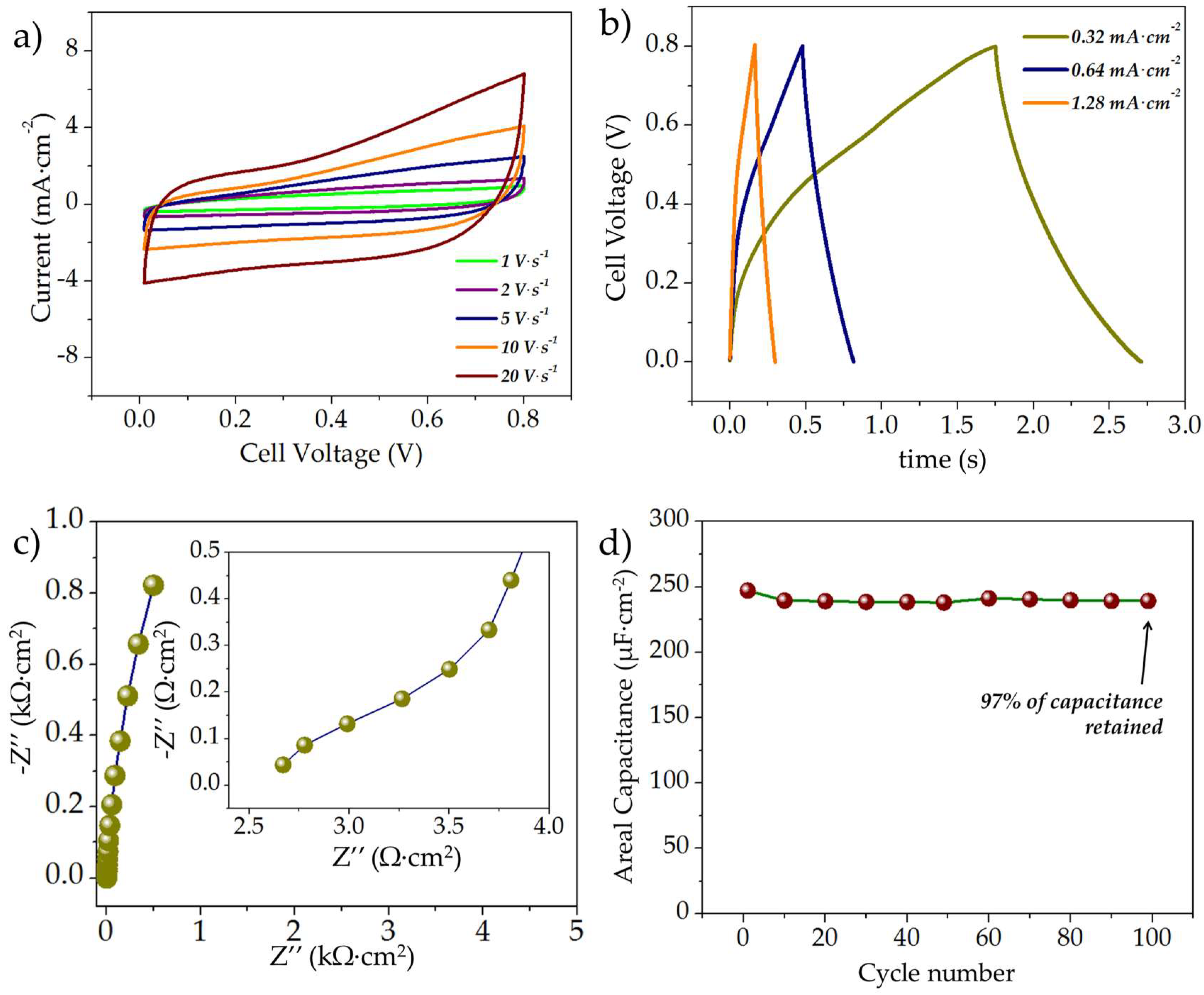
The electrochemical characteristics of the rGO//rGO symmetric MSC are shown in Figure 4. The typical CV curves of the symmetric rGO//rGO MSCs at scan rates of 1, 2, 5, 10, and 20 V·s−1 are shown in Figure 4a. As evident, even at a high scan rate of 20 V·s−1, the curves maintain a predominantly rectangular shape, which is indicative of capacitive charge storage. The typical GCD curves of the rGO//rGO MSCs at different current rates are shown in Figure 4b; the discharge areal capacitances were estimated as ~252, 223, and 172 µF·cm−2 at current densities of 0.32, 0.64, and 1.28 mA·cm−2, respectively. Figure 4c shows the typical Nyquist plots of the rGO//rGO MSCs scanned for a frequency range of 100,000–0.01 Hz; as evident the curves comprised a depressed semicircular region in the high frequency regime followed by a linear slope in the low-frequency region, indicating typical capacitive behavior; the diameter of the semicircular region was ~0.0035 kΩ·cm2 (~11 Ω), indicating very low charge transfer resistance; the x-axis intercept was ~8 Ω mainly due to solution resistance. The typical cycling behavior of the rGO//rGO microsupercapacitor is illustrated in Figure 4d; the capacitor exhibited very stable cycling with a capacitive retention of ~97% after 100 cycles.
3.2.2. Electrochemical Characterization of the MnOx//MnOx Symmetric MSCs
The electrochemical characteristics of the MnOx//MnOx symmetric MSCs are shown in Figure 5. The typical cyclic voltammograms (CV) of the symmetric MnOx//MnOx MSCs at scan rates of 1, 2, 5, 10, and 20 V·s−1 are shown in Figure 5a. As evident, even at a high scan rate of 20 V·s−1, the curves exhibit predominantly capacitive shape with some depressed redox peaks around 0.5–0.6 V, which could be attributed to the pseudocapacitive charge storage characteristics of the manganese oxide active material. The typical GCD curves at different current densities are shown in Figure 5b; the GCD curves display triangular sloping-desloping behavior for a voltage range of 0–0.8 V with some curvature. The discharge areal capacitances were estimated as 147, 96, 64 µF·cm−2 at current densities of 0.16, 0.32, 0.64 mA·cm−2, respectively. Figure 5c shows the typical Nyquist plots of the freshly prepared MnOx//MnOx MSCs scanned for a frequency range of 100,000–0.01 Hz. As evident the curves comprised a depressed semicircular region in the high frequency regime followed by a linear slope in the low-frequency region, indicating typical redox behavior. The diameter of the semicircular region was ~0.02 kΩ·cm−2 (~60 Ω) indicating low charge-transfer resistance. The typical cyclability and the capacitance retention of the MnOx//MnOx MSC are shown in Figure 5d; ~58% of the initial capacitance was retained after 1000 cycles. The drop in capacitance was observed in previous reports documenting the use of MnOx for symmetric MSCs, and could be a result of the possible dissolution of the electro-active materials, which is an intrinsic issue with manganese oxides [43,44].
3.2.3. Electrochemical Evaluation of the Asymmetric rGO//MnOx MSCs
As seen in the previous sections, the areal capacitance of rGO//rGO MSC was higher than that of the MnOx//MnOx MSC (~252 μF·cm−2 as opposed to 96 μF·cm−2 at a current density of 0.32 mA·cm−2), as a result of which, three different MnOx thicknesses (MnOx deposited at 0.6, 0.9, and 1.2 C·cm−2) were evaluated for asymmetric systems in order to investigate the optimal energy-power tradeoff. The asymmetric MSCs were designated as rGO//MnOx-0.6C, rGO//MnOx-0.9C and rGO//MnOx-1.2C, where the suffix symbolizes the charge used for MnOx deposition. The electrochemical characteristics of the asymmetric rGO//MnOx-0.9C MSC are shown in Figure 6, whereas the electrochemical characteristics of the rGO//MnOx-0.6C and rGO//MnOx-1.2C MSCs can be found in the supplementary file (Figure S2). The typical CV curves of asymmetric rGO//MnOx-0.9C MSC at different scan rates are shown in Figure 6a. As evident the current response of the asymmetric rGO//MnOx-0.9C MSC was higher than that of both the symmetric rGO//rGO and MnOx//MnOx capacitors. Furthermore, composite charge storage characteristics are evident from the shape of the CV curves. GCD curves of the asymmetric rGO//MnOx-0.9C MSC at different current densities are shown in Figure 6b; the discharge areal capacitances were estimated as 1.59, 1.29, and 1.2 mF·cm−2 at current densities of 0.64, 1.28, and 2.56 mA·cm−2, respectively. The Nyquist plot of the asymmetric rGO//MnOx-0.9C MSC scanned for a frequency range of 100,000–0.01 Hz is shown in Figure 6c and the inset depicts the zoomed-in high-frequency response of the MSC. The diameter of semicircular region was ~0.07 kΩ·cm−2 (~218 Ω), higher than both the symmetric rGO//rGO and MnOx//MnOx MSCs. The relatively higher charge-transfer resistivity can be attributed to the larger thickness of the manganese oxide component on the asymmetric MSC. The typical cycling performance of the asymmetric rGO//MnOx-0.9C MSC is shown in Figure 6d; the capacitor retained a capacitance of ~85% after 1000 cycles, which is much superior to that of the MnOx//MnOx MSC.
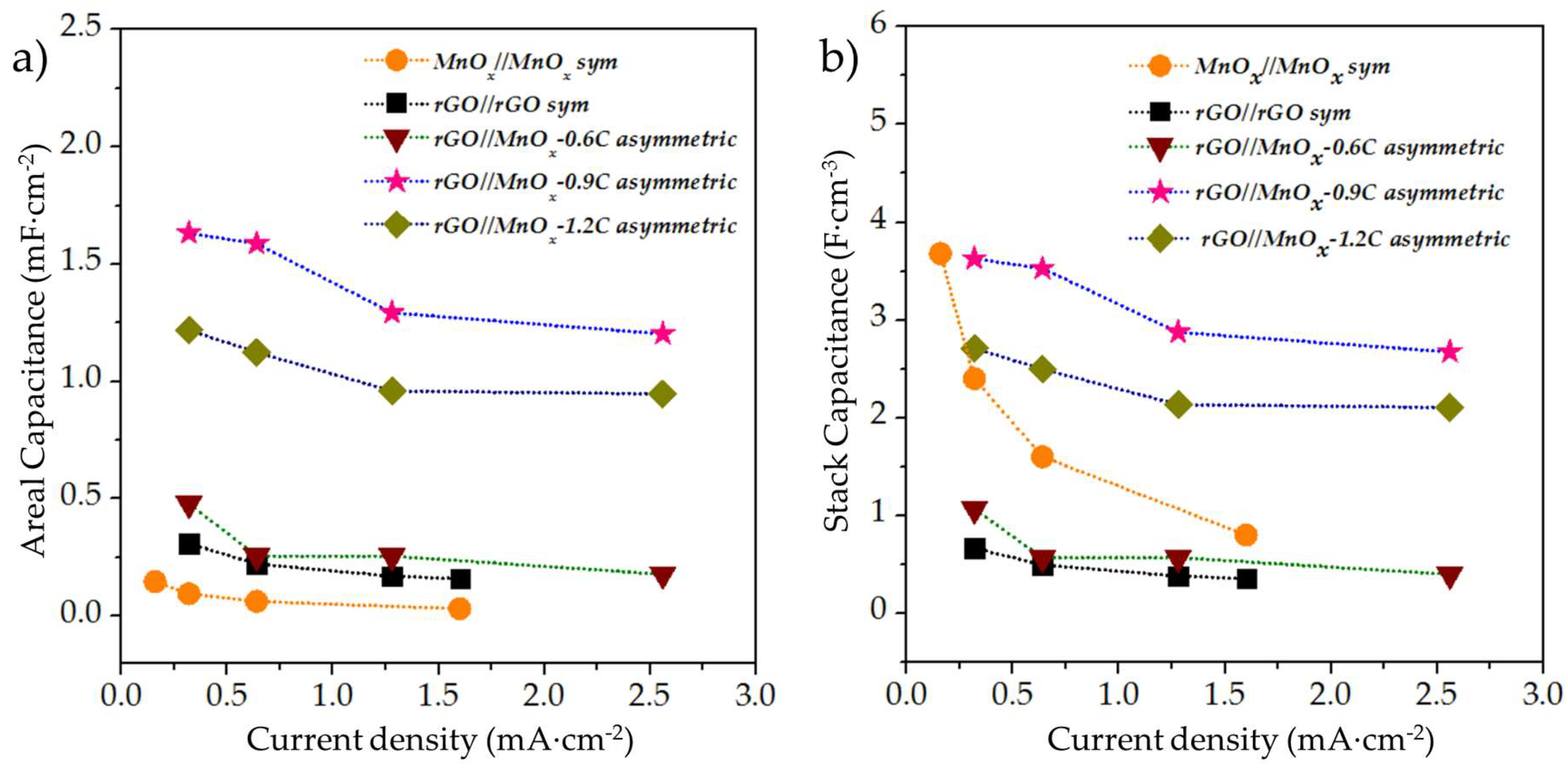
The comparitive rate capability of the different MSCs evaluated in this work is shown in Figure 7a,b. While areal normalization is essential in terms of practicality of miniaturized devices, stack calculations can provide with more insight into the intrinsic properties of the materials utilized for the MSC construction. The stack capacitances of all the asymmetric MSCs as well as the rGO//rGO MSC were normalized with the thickness of the rGO film, whereas the stack parameters for the MnOx//MnOx symmetric capacitor were normalized with the thickness of the MnOx film. From Figure 7, it is clear that the asymmetric rGO//MnOx-0.6C, rGO//MnOx-0.9C, and rGO//MnOx-1.2C MSCs as well as the symmetric rGO//rGO MSC followed the same trend for both the areal and stack capacitances with the highest values for rGO//MnOx-0.9C followed by the rGO//MnOx-1.2C, rGO//MnOx-0.6C and the rGO//rGO MSC (in that order). The only discrepancy in stack and areal capacitance was exhibited by the symmetric MnOx//MnOx system, which can be explained by the relatively lower thickness of the MnOx as compared to the rGO film. The stack capacitance of the MnOx//MnOx system fades quickly with increasing current, which can be attributed to the use of pristine MnOx as electro-active material without the addition of any conducting additives.
The areal capacitance, energy and power densities of the MSCs were computed using Equations (1)–(3), respectively
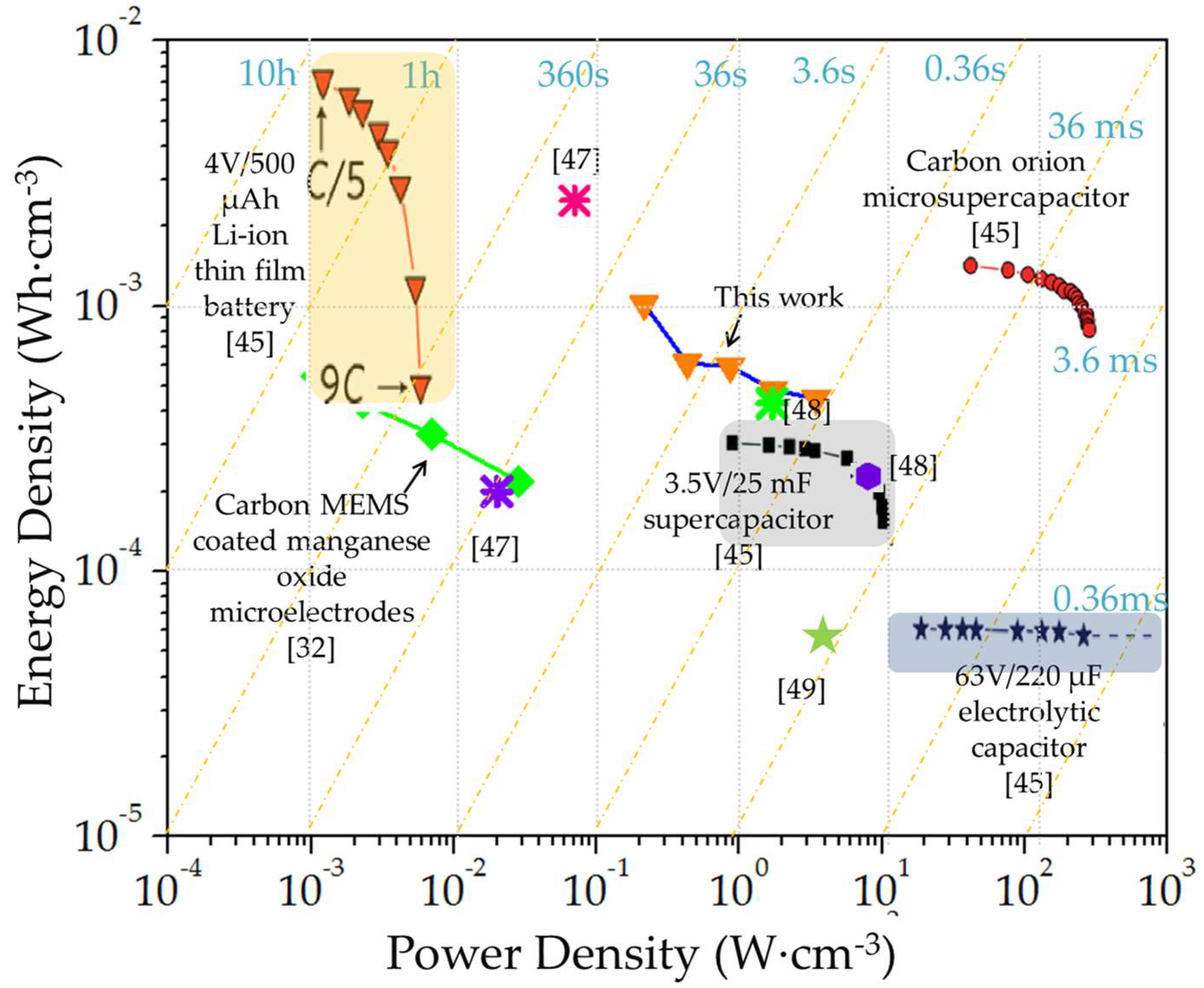
where Careal (F·cm−2), EDareal (Wh·cm−2) and PDareal (W·cm−2) refer to areal capacitance, energy and power density, respectively, I is the discharge current density (A·cm−2), ΔV is the voltage window (V), and Δt is the discharge time (s). The stack capacitance, energy and power densities were calculated by normalizing the Careal, EDareal and PDareal with the rGO or MnOx thickness, depending upon the higher thickness. The areal energy-power trade-off between all the MSC devices constructed in this work has been depicted in a Ragone chart (Figure S3); the asymmetric rGO//MnOx-0.9C MSC was able to deliver an energy density of 0.274 μWh·cm−2 at a power density of 193.6 μW·cm−2 (pertaining to a capacitance of 1.63 mF·cm−2) which is higher than other reports documenting on-chip MnOx-based systems [32,35] but lower than reports on carbon onions and conjugated polymers [45,46]. A comparative Ragone chart depicting the stack energy and power densities of the asymmetric rGO//MnOx-0.9C MSC along with other commercial EES [45] as well as other MSC systems reported in the literature is shown in Figure 8. Areal and stack characteristics of the asymmetric MSC have also been compared with other on-chip MSCs in Table 1. The asymmetric MSC was able to deliver a maximal stack energy density of 1.02 mWh·cm−3 at a power density of 0.22 W·cm−3, and a maximal power density of 3.44 W·cm−3 at which an energy density of 0.45 mWh·cm−3 was maintained, resulting in a time constant of 0.47 s. It can be seen that the hybrid MSC is well-placed in between the energy-power characteristics of thin film lithium-ion battery and commercial supercapacitors. It should be noted that the device characteristics have been reported in terms of volume of the interdigitated fingers and the values will diminish taking packaging into account. Furthermore, the coulombic efficiency of the MSC systems was relatively low, which could be ascribed to the predominant use of oxides and improvement is expected with the addition of nanostructured conducting agents. Additionally, while the aqueous asymmetric MSC displays high energy and power tradeoff, further enhancement in electrochemical performance is expected with the use of high voltage electrolytes, advanced hierarchical materials, as well as more balanced hybrid designs, which are subjects of future works.
4. Conclusions
In summary, interdigitated microsupercapacitors were fabricated using photolithography, lift-off and electrodeposition methods. Symmetric MnOx//MnOx, rGO//rGO as well as asymmetric rGO//MnOx microsupercapacitors with three different MnOx thicknesses were constructed and evaluated. The asymmetric microsupercapacitor with the MnOx film deposited at a charge of 0.9 C·cm−2 displayed the optimal energy-power trade-off much superior to that of both the symmetric and well as the other asymmetric configurations. The rGO//MnOx-0.9C microsupercapacitor exhibited a high stack energy density of 1.02 mWh·cm−3 and a maximal power density of 3.44 W·cm−3 both of which are comparable with thin film batteries and commercial supercapacitors in terms of volumetric energy and power densities, respectively. The high energy-power trade-off of the device is attributed to the synergistic effects of utilizing double layer and pseudocapacitive charge storage mechanisms along with in-plane interdigital design within one optimized micro-device.
Supplementary Materials
The following are available online at https://www.mdpi.com/2072-666X/9/8/399/s1, Figure S1: Microstructure of the single layer graphene oxide (SLGO); Figure S2: Typical cyclic voltammograms at different scan rates of (a) the asymmetric rGO//MnOx-0.6C MSC and (b) the asymmetric rGO//MnOx-1.2C MSC; typical GCD curves of (c) the asymmetric rGO//MnOx-0.6C MSC and (d) the asymmetric rGO//MnOx-1.2C MSC; cycle life of (e) the asymmetric rGO//MnOx-0.6C MSC and (f) the asymmetric rGO//MnOx-1.2C MSC; Figure S3: Ragone chart of the different MSC systems.
Author Contributions
C.W. supervised the research; R.A. and C.W. conceived the idea and designed the experiments; R.A. and C.W. interpreted the data and discussed the results; R.A. wrote the original draft and C.W. reviewed the final manuscript.
Funding
This work was partially supported by the National Science Foundation (NSF) projects (1506640, 1509735, and 1611088) and the NSF Nanosystems Engineering Research Center (NERC) for Advanced Self-Powered Systems of Integrated Sensors and Technologies (ASSIST) center seed funding.
Acknowledgments
R.A. gratefully acknowledges the University Graduate School (UGS) at Florida International University for support through a Dissertation Year Fellowship (DYF). The authors are also thankful to the staff of Advanced Materials Engineering Research Institute (AMERI) for their kind assistance with experimentation.
Conflicts of Interest
The authors declare no conflict of interest.
References
- Beidaghi, M.; Gogotsi, Y. Capacitive energy storage in micro-scale devices: Recent advances in design and fabrication of micro-supercapacitors. Energy Environ. Sci. 2014, 7, 867–884. [Google Scholar] [CrossRef]
- Agrawal, R.; Chen, C.; Hao, Y.; Song, Y.; Wang, C. Graphene for supercapacitors. In Graphene Based Energy Devices; Rashid bin Mohd Yusoff, A., Ed.; Wiley-VCH Verlag GmbH & Co. KGaA: Weinheim, Germany, 2015; pp. 171–214. [Google Scholar]
- Algharaibeh, Z.; Liu, X.; Pickup, P.G. An asymmetric anthraquinone-modified carbon/ruthenium oxide supercapacitor. J. Power Sources 2009, 187, 640–643. [Google Scholar] [CrossRef]
- Khomenko, V.; Raymundo-Pinero, E.; Béguin, F. Optimisation of an asymmetric manganese oxide/activated carbon capacitor working at 2 V in aqueous medium. J. Power Sources 2006, 153, 183–190. [Google Scholar] [CrossRef]
- Long, J.W.; Bélanger, D.; Brousse, T.; Sugimoto, W.; Sassin, M.B.; Crosnier, O. Asymmetric electrochemical capacitors—Stretching the limits of aqueous electrolytes. MRS Bull. 2011, 36, 513–522. [Google Scholar] [CrossRef]
- Hong, M.S.; Lee, S.H.; Kim, S.W. Use of KCl aqueous electrolyte for 2 V manganese oxide/activated carbon hybrid capacitor. Electrochem. Solid-State Lett. 2002, 5, A227–A230. [Google Scholar] [CrossRef]
- Liu, H.; Zhao, K. Asymmetric flow electrochemical capacitor with high energy densities based on birnessite-type manganese oxide nanosheets and activated carbon slurries. J. Mater. Sci. 2016, 51, 9306–9313. [Google Scholar] [CrossRef]
- Chen, L.F.; Huang, Z.H.; Liang, H.W.; Guan, Q.F.; Yu, S.H. Bacterial-cellulose-derived carbon nanofiber@MnO2 and nitrogen-doped carbon nanofiber electrode materials: An asymmetric supercapacitor with high energy and power density. Adv. Mater. 2013, 25, 4746–4752. [Google Scholar] [CrossRef] [PubMed]
- Wang, D.W.; Li, F.; Cheng, H.M. Hierarchical porous nickel oxide and carbon as electrode materials for asymmetric supercapacitor. J. Power Sources 2008, 185, 1563–1568. [Google Scholar] [CrossRef]
- Ye, X.-D.; Hu, J.-G.; Yang, Q.; Zheng, Y.-F.; Huang, W.-Z. Preparation and properties of NiO/AC asymmetric capacitor. J. Inorg. Mater. 2014, 29, 250–256. [Google Scholar]
- Sivakkumar, S.R.; Pandolfo, A.G. Evaluation of lithium-ion capacitors assembled with pre-lithiated graphite anode and activated carbon cathode. Electrochim. Acta 2012, 65, 280–287. [Google Scholar] [CrossRef]
- Yu, X.; Zhan, C.; Lv, R.; Bai, Y.; Lin, Y.; Huang, Z.H.; Shen, W.; Qiu, X.; Kang, F. Ultrahigh-rate and high-density lithium-ion capacitors through hybriding nitrogen-enriched hierarchical porous carbon cathode with prelithiated microcrystalline graphite anode. Nano Energy 2015, 15, 43–53. [Google Scholar] [CrossRef]
- Ren, J.J.; Su, L.W.; Qin, X.; Yang, M.; Wei, J.P.; Zhou, Z.; Shen, P.W. Pre-lithiated graphene nanosheets as negative electrode materials for Li-ion capacitors with high power and energy density. J. Power Sources 2014, 264, 108–113. [Google Scholar] [CrossRef]
- Amatucci, G.G.; Badway, F.; Du Pasquier, A.; Zheng, T. An asymmetric hybrid nonaqueous energy storage cell. J. Electrochem. Soc. 2001, 148, A930–A939. [Google Scholar] [CrossRef]
- Agrawal, R.; Chen, C.; Dages, S.; Wang, C. A high energy 3V lithium-ion capacitor synthesized via electrostatic spray deposition. Adv. Mater. Lett. 2017, 8, 783–790. [Google Scholar] [CrossRef]
- Agrawal, R.; Hao, Y.; Song, Y.; Chen, C.; Wang, C. Hybridization of lithium-ion batteries and electrochemical capacitors: Fabrication and challenges. In Proceedings of the 2015 SPIE Sensing Technology + Applications, Baltimore, MD, USA, 20–24 April 2015. [Google Scholar]
- Naoi, K.; Ishimoto, S.; Miyamoto, J.I.; Naoi, W. Second generation ‘nanohybrid supercapacitor’: Evolution of capacitive energy storage devices. Energy Environ. Sci. 2012, 5, 9363–9373. [Google Scholar] [CrossRef]
- Hu, X.; Huai, Y.; Lin, Z.; Suo, J.; Deng, Z. A (LiFePO4–AC)/Li4Ti5O12 hybrid battery capacitor. J. Electrochem. Soc. 2007, 154, A1026–A1030. [Google Scholar] [CrossRef]
- Hu, X.B.; Lin, Z.J.; Liu, L.; Huai, J.Y.; Deng, H.Z. Effects of the LiFePO4 content and the preparation method on the properties of (LiFePO4 + AC)/Li4Ti5O12 hybrid batterycapacitors. J. Serb. Chem. Soc. 2010, 75, 1259–1269. [Google Scholar] [CrossRef]
- Zhai, Y.; Dou, Y.; Zhao, D.; Fulvio, P.F.; Mayes, R.T.; Dai, S. Carbon materials for chemical capacitive energy storage. Adv. Mater. 2011, 23, 4828–4850. [Google Scholar] [CrossRef] [PubMed]
- Zhi, M.; Xiang, C.; Li, J.; Li, M.; Wu, N. Nanostructured carbon–metal oxide composite electrodes for supercapacitors: A review. Nanoscale 2013, 5, 72–88. [Google Scholar] [CrossRef] [PubMed]
- Bonaccorso, F.; Colombo, L.; Yu, G.; Stoller, M.; Tozzini, V.; Ferrari, A.C.; Ruoff, R.S.; Pellegrini, V. Graphene, related two-dimensional crystals, and hybrid systems for energy conversion and storage. Science 2015, 347, 1246501. [Google Scholar] [CrossRef] [PubMed]
- Dreyer, D.R.; Park, S.; Bielawski, C.W.; Ruoff, R.S. The chemistry of graphene oxide. Chem. Soc. Rev. 2010, 39, 228–240. [Google Scholar] [CrossRef] [PubMed]
- Flyunt, R.; Knolle, W.; Kahnt, A.; Prager, A.; Lotnyk, A.; Malig, J.; Guldi, D.; Abel, B. Mechanistic aspects of the radiation-chemical reduction of graphene oxide to graphene-like materials. Int. J. Radiat. Biol. 2014, 90, 486–494. [Google Scholar] [CrossRef] [PubMed]
- Kuila, T.; Mishra, A.K.; Khanra, P.; Kim, N.H.; Lee, J.H. Recent advances in the efficient reduction of graphene oxide and its application as energy storage electrode materials. Nanoscale 2013, 5, 52–71. [Google Scholar] [CrossRef] [PubMed]
- Diba, M.; Fam, D.W.; Boccaccini, A.R.; Shaffer, M.S. Electrophoretic deposition of graphene-related materials: A review of the fundamentals. Prog. Mater. Sci. 2016, 82, 83–117. [Google Scholar] [CrossRef] [Green Version]
- An, S.J.; Zhu, Y.; Lee, S.H.; Stoller, M.D.; Emilsson, T.; Park, S.; Velamakanni, A.; An, J.; Ruoff, R.S. Thin film fabrication and simultaneous anodic reduction of deposited graphene oxide platelets by electrophoretic deposition. J. Phys. Chem. Lett. 2010, 1, 1259–1263. [Google Scholar] [CrossRef]
- Zhang, H.; Zhang, X.; Zhang, D.; Sun, X.; Lin, H.; Wang, C.; Ma, Y. One-step electrophoretic deposition of reduced graphene oxide and Ni(OH)2 composite films for controlled syntheses supercapacitor electrodes. J. Phys. Chem. B 2012, 117, 1616–1627. [Google Scholar] [CrossRef] [PubMed]
- Wang, J.G.; Kang, F.; Wei, B. Engineering of MnO2-based nanocomposites for high-performance supercapacitors. Prog. Mater. Sci. 2015, 74, 51–124. [Google Scholar] [CrossRef]
- Wang, G.; Zhang, L.; Zhang, J. A review of electrode materials for electrochemical supercapacitors. Chem. Soc. Rev. 2012, 41, 797–828. [Google Scholar] [CrossRef] [PubMed] [Green Version]
- Wei, W.; Cui, X.; Chen, W.; Ivey, D.G. Manganese oxide-based materials as electrochemical supercapacitor electrodes. Chem. Soc. Rev. 2011, 40, 1697–1721. [Google Scholar] [CrossRef] [PubMed]
- Agrawal, R.; Adelowo, E.; Baboukani, A.R.; Villegas, M.F.; Henriques, A.; Wang, C. Electrostatic spray deposition-based manganese oxide films—From pseudocapacitive charge storage materials to three-dimensional microelectrode integrands. Nanomaterials 2017, 7, 198. [Google Scholar] [CrossRef] [PubMed]
- Shen, C.; Wang, X.; Li, S.; Zhang, W.; Kang, F. A high-energy-density micro supercapacitor of asymmetric MnO2–carbon configuration by using micro-fabrication technologies. J. Power Sources 2013, 234, 302–309. [Google Scholar] [CrossRef]
- Dinh, T.M.; Mesnilgrente, F.; Conédéra, V.; Kyeremateng, N.A.; Pech, D. Realization of an asymmetric interdigitated electrochemical micro-capacitor based on carbon nanotubes and manganese oxide. J. Electrochem. Soc. 2015, 162, A2016–A2020. [Google Scholar] [CrossRef]
- El-Kady, M.F.; Ihns, M.; Li, M.; Hwang, J.Y.; Mousavi, M.F.; Chaney, L.; Lech, A.T.; Kaner, R.B. Engineering three-dimensional hybrid supercapacitors and microsupercapacitors for high-performance integrated energy storage. Proc. Natl. Acad. Sci. USA 2015, 112, 4233–4238. [Google Scholar] [CrossRef] [PubMed] [Green Version]
- Liu, W.W.; Feng, Y.Q.; Yan, X.B.; Chen, J.T.; Xue, Q.J. Superior micro-supercapacitors based on graphene quantum dots. Adv. Funct. Mater. 2013, 23, 4111–4122. [Google Scholar] [CrossRef]
- Beidaghi, M.; Wang, C. Micro-supercapacitors based on interdigital electrodes of reduced graphene oxide and carbon nanotube composites with ultrahigh power handling performance. Adv. Funct. Mater. 2012, 22, 4501–4510. [Google Scholar] [CrossRef]
- Chaiyakun, S.; Witit-Anun, N.; Nuntawong, N.; Chindaudom, P.; Oaew, S.; Kedkeaw, C.; Limsuwan, P. Preparation and characterization of graphene oxide nanosheets. Procedia Eng. 2012, 32, 759–764. [Google Scholar]
- González, M.G.; Cabanelas, J.C.; Baselga, J. Applications of FTIR on epoxy resins-identification, monitoring the curing process, phase separation and water uptake. In Infrared Spectroscopy-Materials Science, Engineering and Technology; Theophanides Theo., Ed.; InTech: London, UK, 2012. [Google Scholar]
- Sim, L.C.; Leong, K.H.; Ibrahim, S.; Saravanan, P. Graphene oxide and Ag engulfed TiO2 nanotube arrays for enhanced electron mobility and visible-light-driven photocatalytic performance. J. Mater. Chem. A 2014, 2, 5315–5322. [Google Scholar] [CrossRef]
- Wang, H.; Lu, Z.; Qian, D.; Li, Y.; Zhang, W. Single-crystal α-MnO2 nanorods: Synthesis and electrochemical properties. Nanotechnology 2007, 18, 115616. [Google Scholar] [CrossRef]
- Yang, R.; Wang, Z.; Dai, L.; Chen, L. Synthesis and characterization of single-crystalline nanorods of α-MnO2 and γ-MnOOH. Mater. Chem. Phys. 2005, 93, 149–153. [Google Scholar] [CrossRef]
- Wang, X.; Myers, B.D.; Yan, J.; Shekhawat, G.; Dravid, V.; Lee, P.S. Manganese oxide micro-supercapacitors with ultra-high areal capacitance. Nanoscale 2013, 5, 4119–4122. [Google Scholar] [CrossRef] [PubMed]
- Bakardjieva, S.; Bezdička, P.; Grygar, T.; Vorm, P. Reductive dissolution of microparticulate manganese oxides. J. Solid-State Electrochem. 2000, 4, 306–313. [Google Scholar] [CrossRef]
- Pech, D.; Brunet, M.; Durou, H.; Huang, P.; Mochalin, V.; Gogotsi, Y.; Taberna, P.L.; Simon, P. Ultrahigh-power micrometre-sized supercapacitors based on onion-like carbon. Nat. Nanotechnol. 2010, 5, 651–654. [Google Scholar] [CrossRef] [PubMed] [Green Version]
- Wang, K.; Zou, W.; Quan, B.; Yu, A.; Wu, H.; Jiang, P.; Wei, Z. An all-solid-state flexible micro-supercapacitor on a chip. Adv. Energy Mater. 2011, 1, 1068–1072. [Google Scholar] [CrossRef]
- Lin, J.; Zhang, C.; Yan, Z.; Zhu, Y.; Peng, Z.; Hauge, R.H.; Natelson, D.; Tour, J.M. 3-dimensional graphene carbon nanotube carpet-based microsupercapacitors with high electrochemical performance. Nano Lett. 2012, 13, 72–78. [Google Scholar] [CrossRef]
- Gao, W.; Singh, N.; Song, L.; Liu, Z.; Reddy, A.L.M.; Ci, L.; Vajtai, R.; Zhang, Q.; Wei, B.; Ajayan, P.M. Direct laser writing of micro-supercapacitors on hydrated graphite oxide films. Nanotechnology 2011, 6, 496–500. [Google Scholar] [CrossRef] [PubMed]
- Zeng, Z.; Long, X.; Zhou, H.; Guo, E.; Wang, X.; Hu, Z. On-chip interdigitated supercapacitor based on nano-porous gold/manganese oxide nanowires hybrid electrode. Electrochim. Acta 2015, 163, 107–115. [Google Scholar] [CrossRef]
Figure 1.
Schematic illustration of the asymmetric rGO//MnOx microsupercapacitor construction.

Figure 2.
(a) FTIR spectra of the starting graphene oxide powders and the EPD reduced graphene oxide films; (b) FTIR spectrum and (c) the X-ray diffraction (XRD) pattern of the electrochemically deposited MnOx films.
Figure 2.
(a) FTIR spectra of the starting graphene oxide powders and the EPD reduced graphene oxide films; (b) FTIR spectrum and (c) the X-ray diffraction (XRD) pattern of the electrochemically deposited MnOx films.
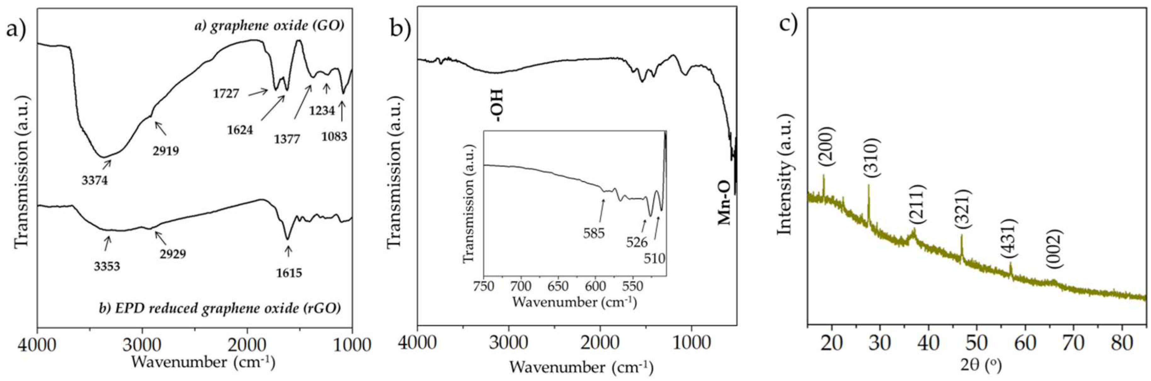
Figure 3.
(a) SEM micrograph of the interdigitated rGO and MnOx microelectrodes; (b) cross sectional view and (c) top view of the rGO coated microelectrodes; (d–f) cross sectional view of the MnOx microelectrodes deposited at 0.6, 0.9 and 1.2 C·cm−2, respectively; (g–i) top-view of the MnOx microelectrodes deposited at 0.6, 0.9 and 1.2 C·cm−2, respectively.
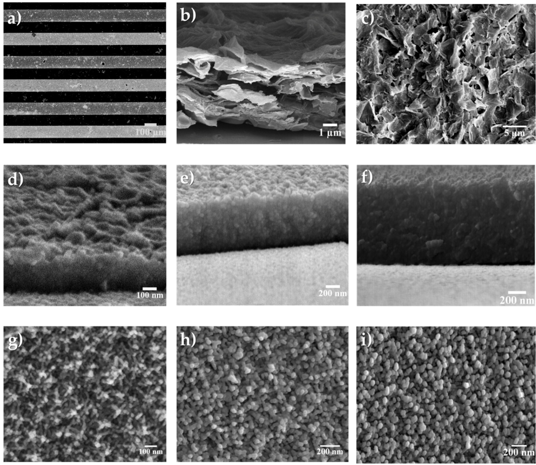
Figure 4.
(a) Typical CV curves (scanned at 1–20 V·s−1); (b) GCD curves at different current densities; (c) EIS spectra (between 100,000–0.01 Hz) and (d) Cycle life of the symmetric rGO//rGO microsupercapacitor.
Figure 4.
(a) Typical CV curves (scanned at 1–20 V·s−1); (b) GCD curves at different current densities; (c) EIS spectra (between 100,000–0.01 Hz) and (d) Cycle life of the symmetric rGO//rGO microsupercapacitor.

Figure 5.
(a) Typical CV curves (scanned at 1–20 V·s−1); (b) GCD curves at different current densities; (c) EIS spectra (between 100,000–0.01 Hz) and (d) cycle life of the symmetric MnOx//MnOx microsupercapacitor.
Figure 5.
(a) Typical CV curves (scanned at 1–20 V·s−1); (b) GCD curves at different current densities; (c) EIS spectra (between 100,000–0.01 Hz) and (d) cycle life of the symmetric MnOx//MnOx microsupercapacitor.
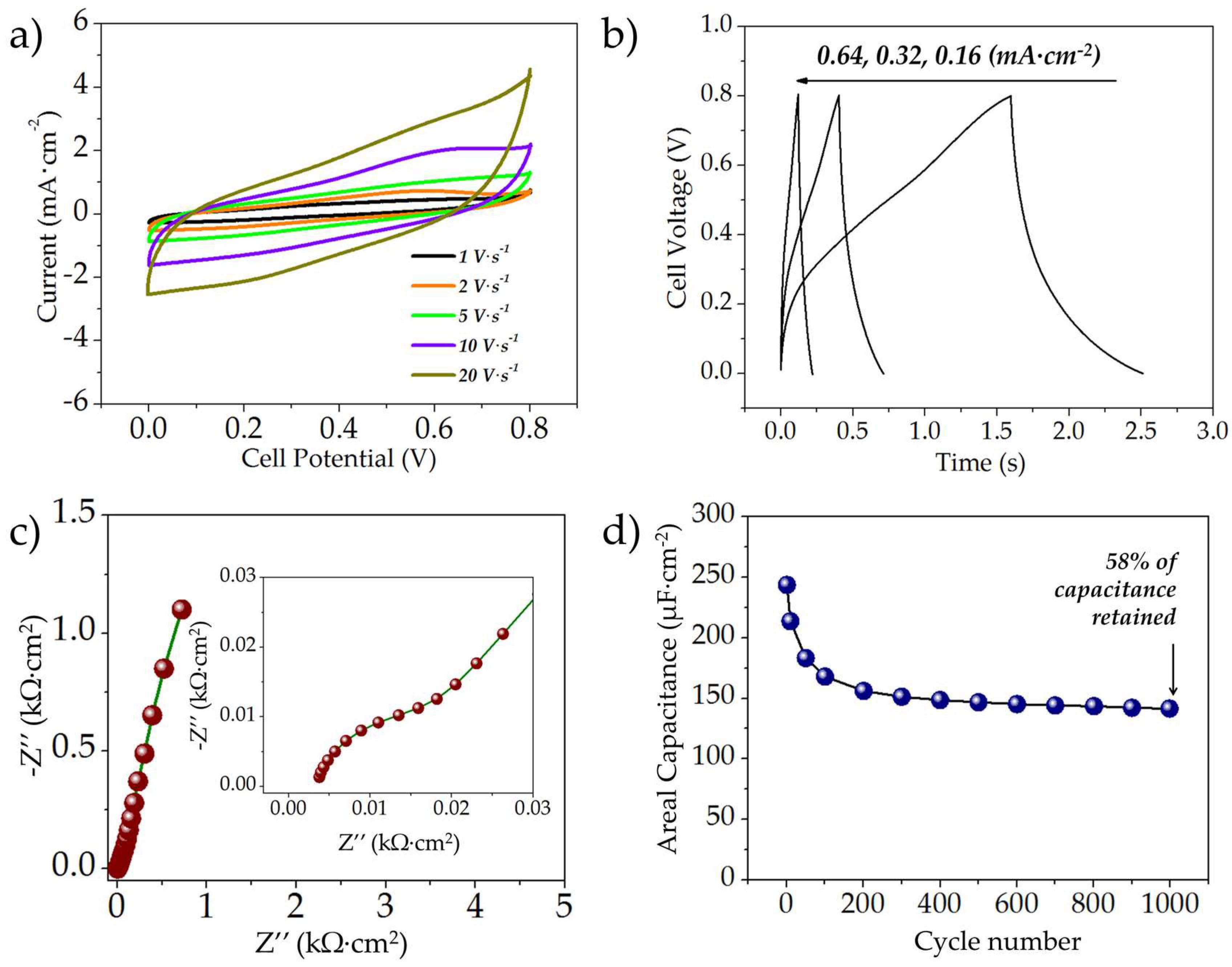
Figure 6.
(a) Typical CV curves (scanned at 5–20 V·s−1); (b) GCD curves at different current densities; (c) EIS spectra (between 100,000–0.01 Hz) and (d) cycle life of the asymmetric rGO//MnOx-0.9C microsupercapacitor.
Figure 6.
(a) Typical CV curves (scanned at 5–20 V·s−1); (b) GCD curves at different current densities; (c) EIS spectra (between 100,000–0.01 Hz) and (d) cycle life of the asymmetric rGO//MnOx-0.9C microsupercapacitor.

Figure 7.
(a) Rate capability of the MnOx//MnOx, rGO//rGO, rGO//MnOx-0.6C, rGO//MnOx-0.9C, and rGO//MnOx-1.2C MSCs in terms of (a) areal and (b) stack capacitances.
Figure 7.
(a) Rate capability of the MnOx//MnOx, rGO//rGO, rGO//MnOx-0.6C, rGO//MnOx-0.9C, and rGO//MnOx-1.2C MSCs in terms of (a) areal and (b) stack capacitances.

Figure 8.
Ragone plot depicting the volumetric energy and power densities exhibited by the asymmetric rGO//MnOx-0.9C MSC in comparison with thin film lithium ion battery, commercial supercapacitors and electrolytic capacitors along with carbon onion-based microsupercapacitors (produced with permission from Reference [45]) and other data points taken from the Reference [32,47,48,49].

Table 1.
Comparison of the asymmetric rGO//MnOx MSC with on-chip MSCs reported in the literature.
| Device Design | Electro-Active Materials | Electrolyte | Specific Capacitance | Energy-Power Characteristics | Ref |
|---|---|---|---|---|---|
| Sandwich | Carbon Microelectromechanical systems (C-MEMS) coated manganese oxide | Aqueous 1 M Na2SO4 | Maximal areal capacitance of 0.055 F·cm−2 and stack capacitance of 7.4 F·cm−3 | Stack energy and power densities of 0.51 mWh·cm−3 and 28.3 mW·cm−3, respectively | [32] |
| Interdigital | Graphene quantum dots//manganese oxide | Aqueous 0.5 M Na2SO4 | 1.1 mF·cm−2 | 0.154 μWh·cm−2 at a specific power of 7.51 μW·cm−2 | [36] |
| Interdigital | Onion-like carbon | 1 M Et4NBF4 in PC | 1.35 F·cm−3 at 1 V·s−1 | Stack energy density of ~1.7 mWh·cm−3 and power density of 200–250 W·cm−3 | [45] |
| Interdigital | Nano-porous gold/MnO2 | (PVA)/H2SO4 | - | Energy density of 55 μWh·cm−3 Power density of 3.4 W·cm−3 | [49] |
| Interdigital | Manganese oxide Reduced graphene oxide | 1 M Na2SO4 | Maximal areal capacitance of 1.63 mF·cm−2, equivalent to a stack/volumetric capacitance of 3.6 F·cm−3 | Maximal energy density of 1.02 mWh·cm−3 Maximal power density of 3.44 W·cm−3 Areal energy density of 0.274 μWh·cm−2 at a power density of 193.6 μW·cm−2 | This work |
© 2018 by the authors. Licensee MDPI, Basel, Switzerland. This article is an open access article distributed under the terms and conditions of the Creative Commons Attribution (CC BY) license (http://creativecommons.org/licenses/by/4.0/).
Share and Cite
MDPI and ACS Style
Agrawal, R.; Wang, C. On-Chip Asymmetric Microsupercapacitors Combining Reduced Graphene Oxide and Manganese Oxide for High Energy-Power Tradeoff. Micromachines 2018, 9, 399. https://doi.org/10.3390/mi9080399
AMA Style
Agrawal R, Wang C. On-Chip Asymmetric Microsupercapacitors Combining Reduced Graphene Oxide and Manganese Oxide for High Energy-Power Tradeoff. Micromachines. 2018; 9(8):399. https://doi.org/10.3390/mi9080399
Chicago/Turabian StyleAgrawal, Richa, and Chunlei Wang. 2018. "On-Chip Asymmetric Microsupercapacitors Combining Reduced Graphene Oxide and Manganese Oxide for High Energy-Power Tradeoff" Micromachines 9, no. 8: 399. https://doi.org/10.3390/mi9080399
Note that from the first issue of 2016, this journal uses article numbers instead of page numbers. See further details here.