
A Method of Three-Dimensional Micro-Rotational Flow Generation for Biological Applications


Abstract
:
1. Introduction
2. Methods and Materials
2.1. Principles
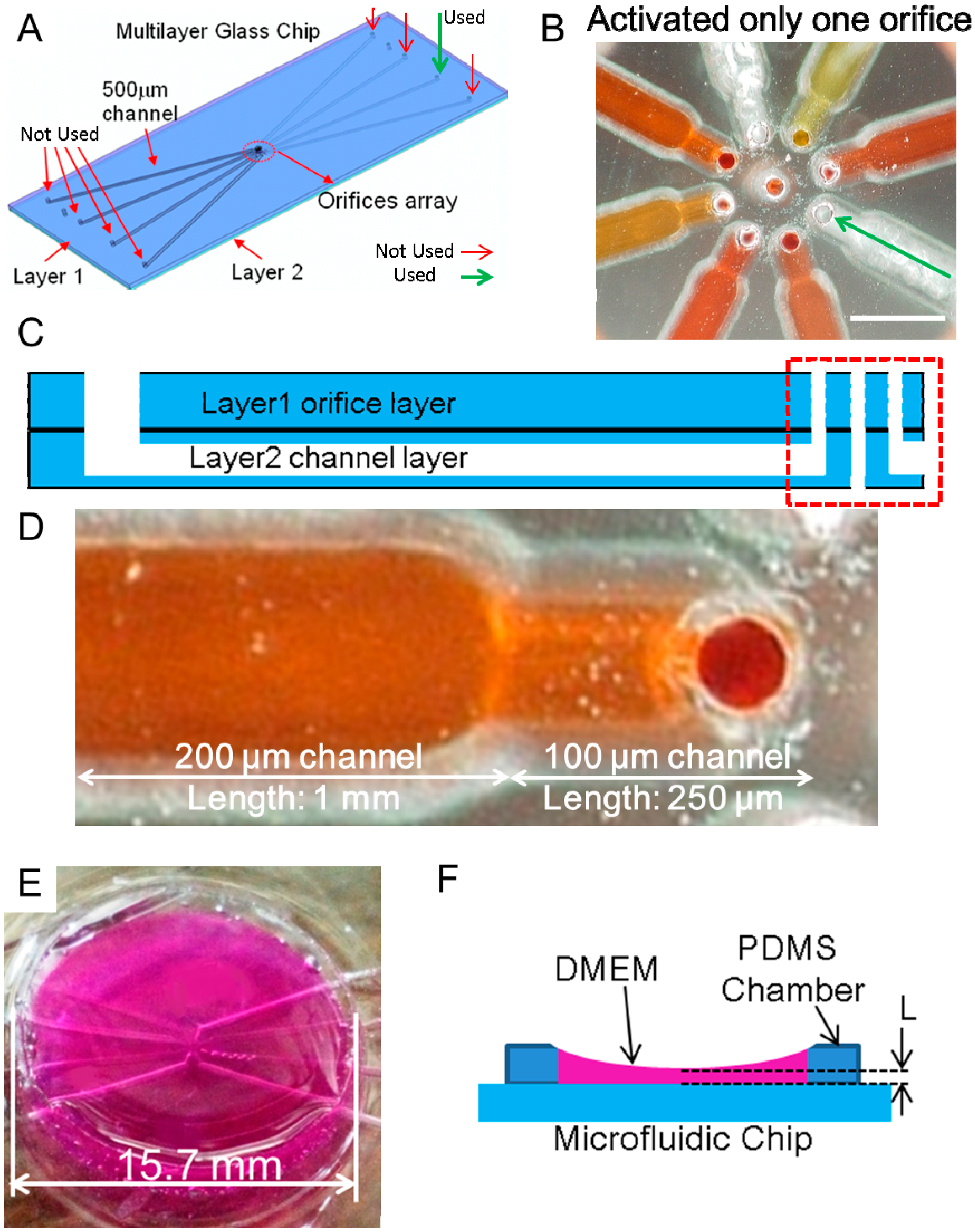
2.2. Material
2.3. Experimental Device and Rotational and Orbital Motion
2.4. CFD Simulation
3. Results
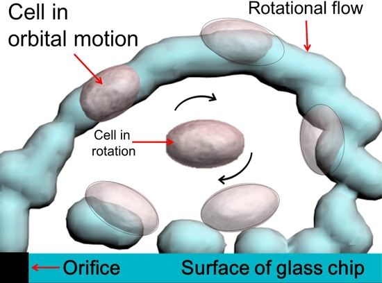
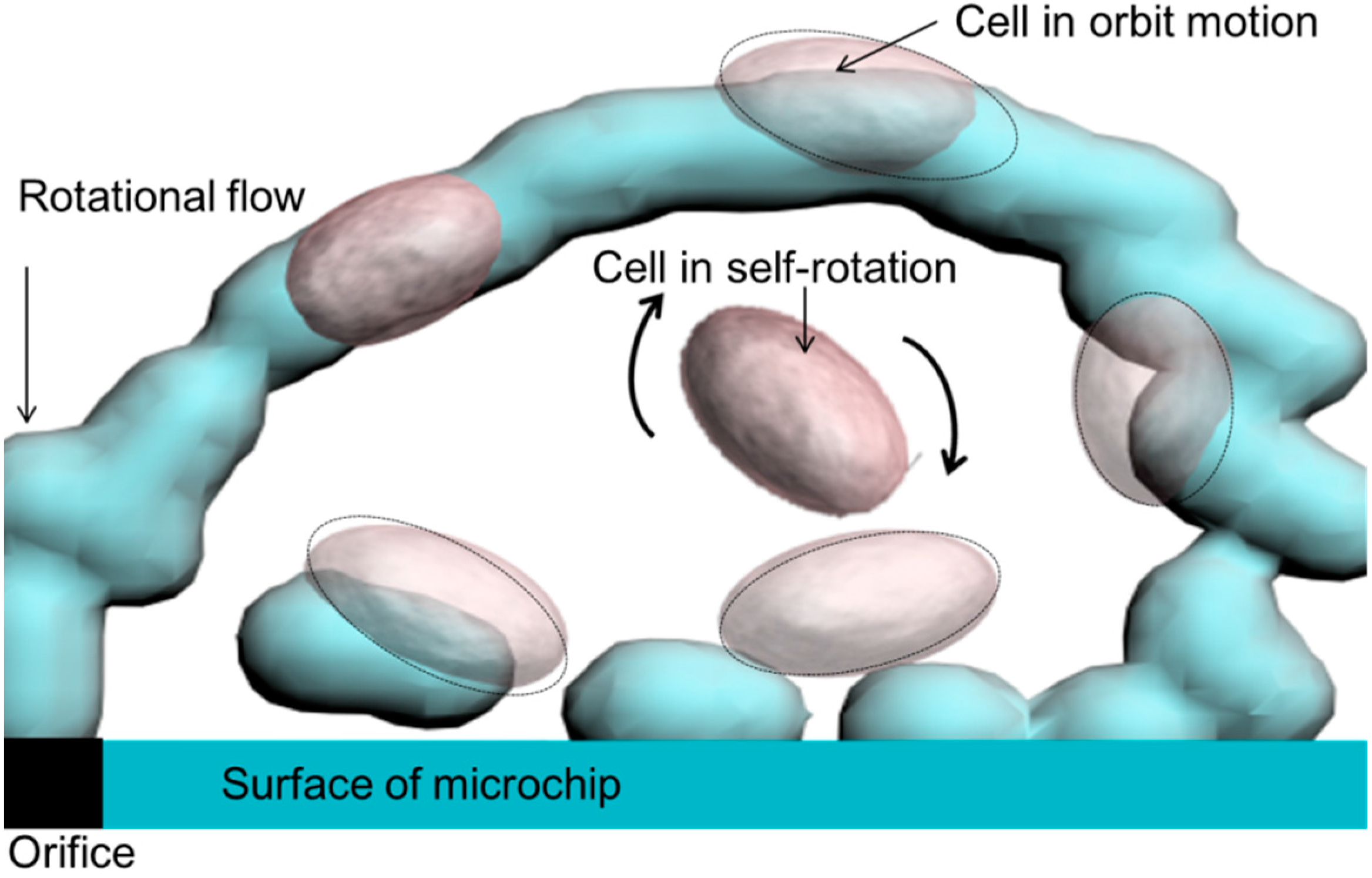
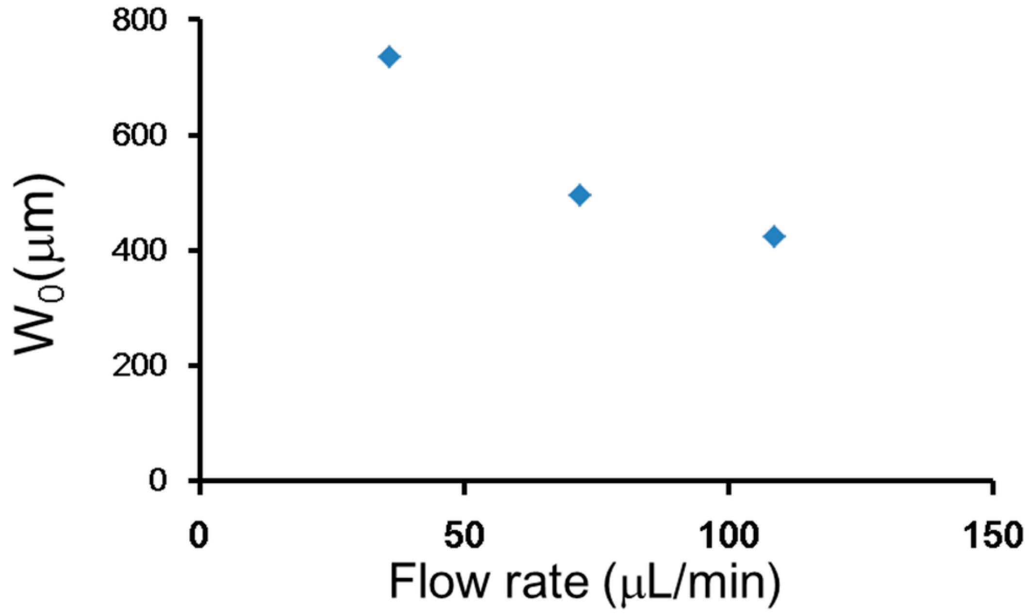
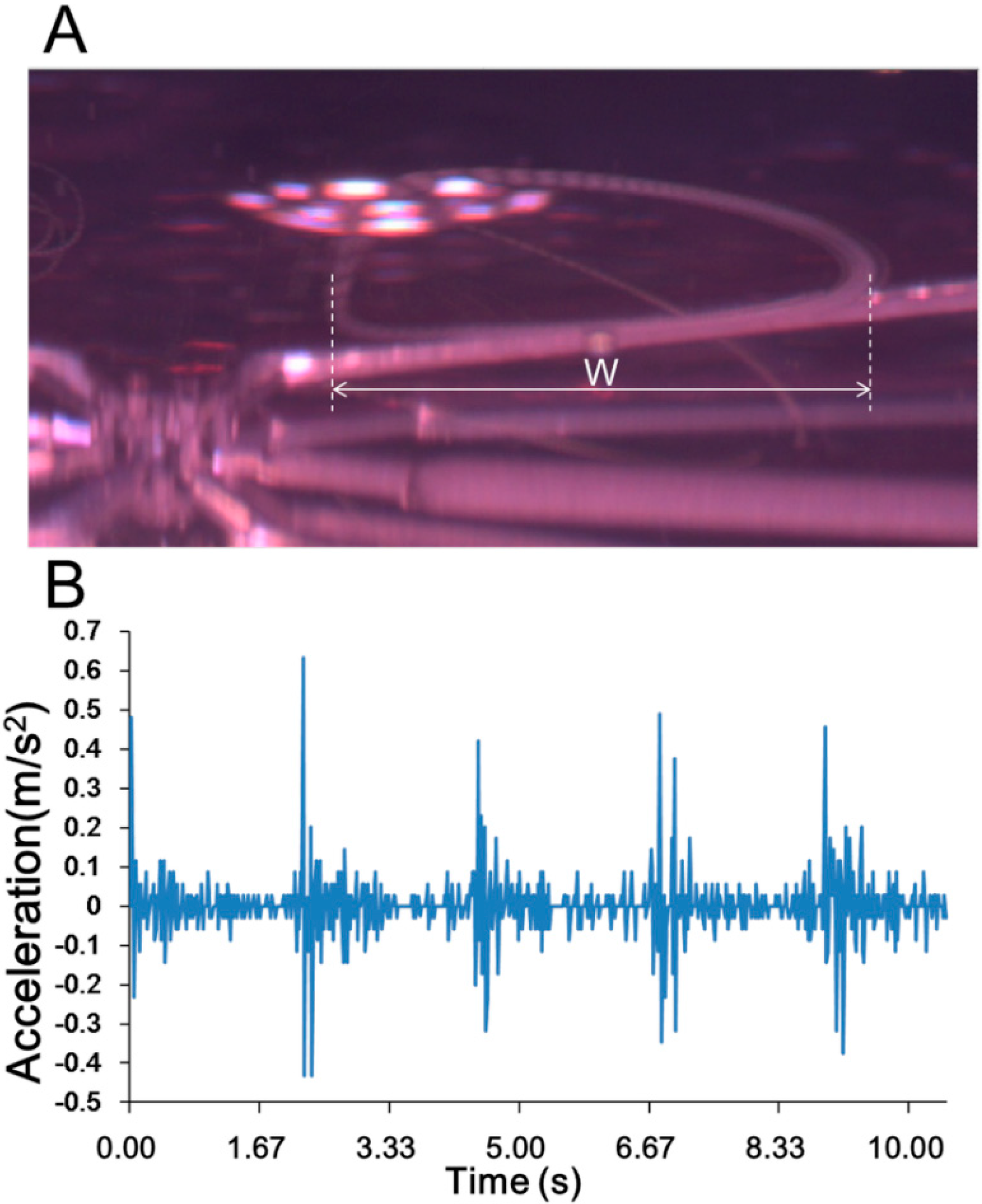
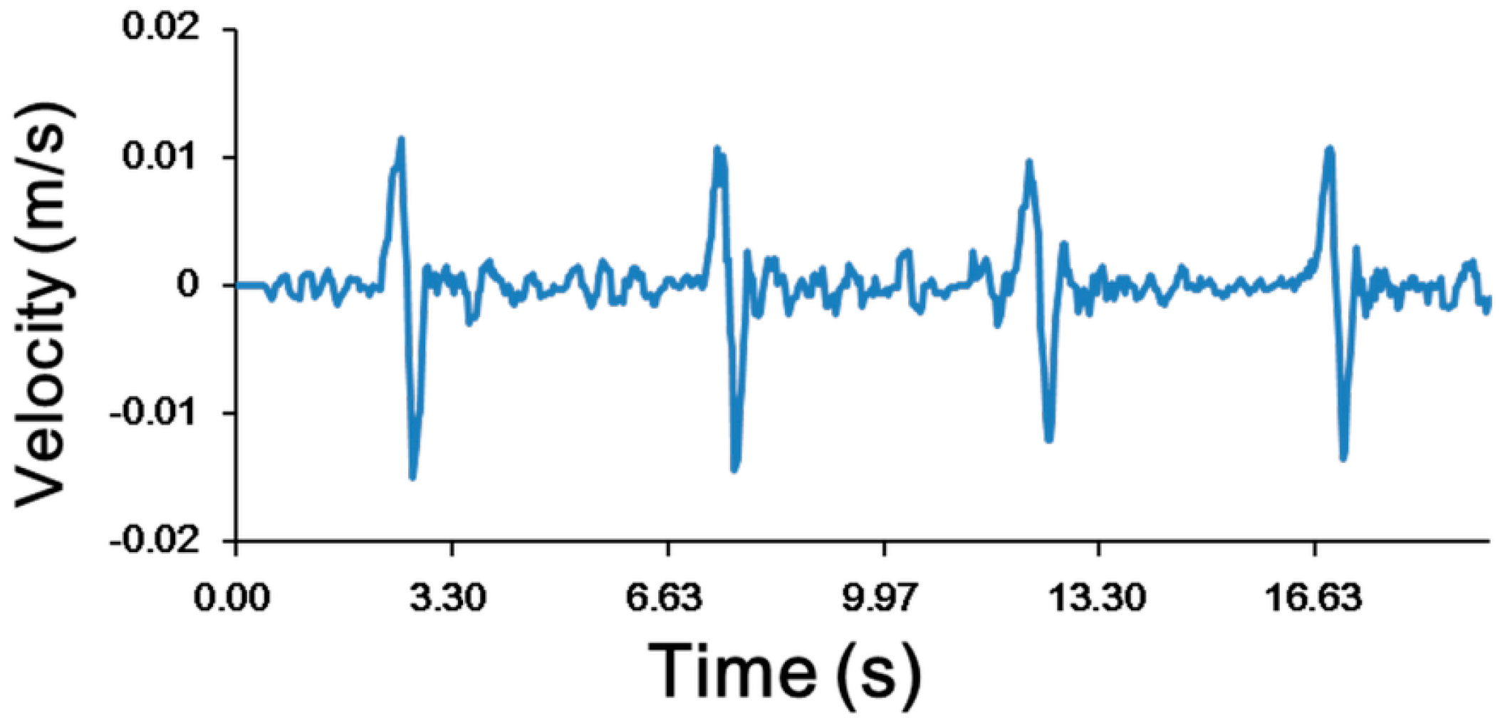
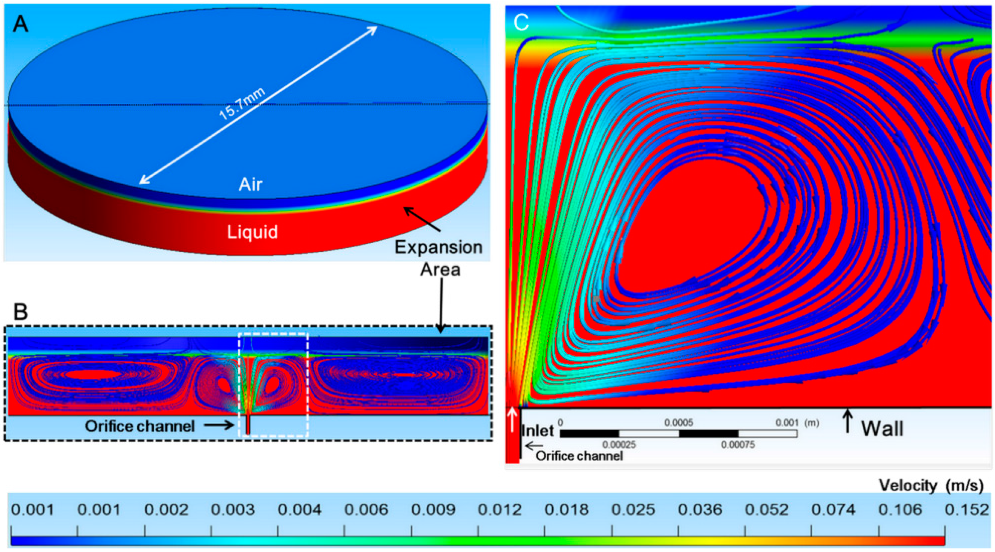
3.1. Experimental Confirmation of the Generation of Micro-Rotational Flow
3.2. Confirmation of the Generation of Micro-Rotational Flow by CFD Simulation
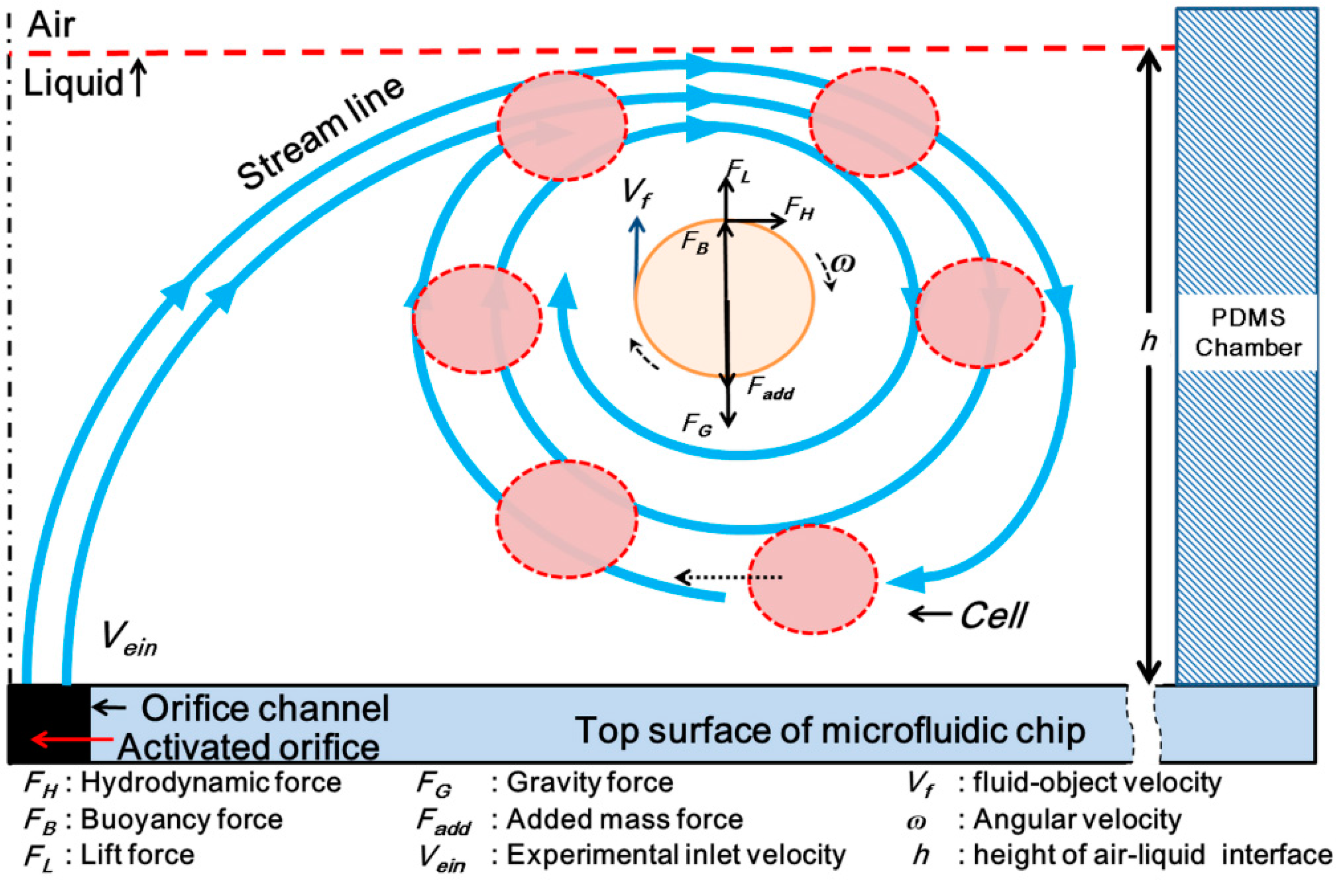
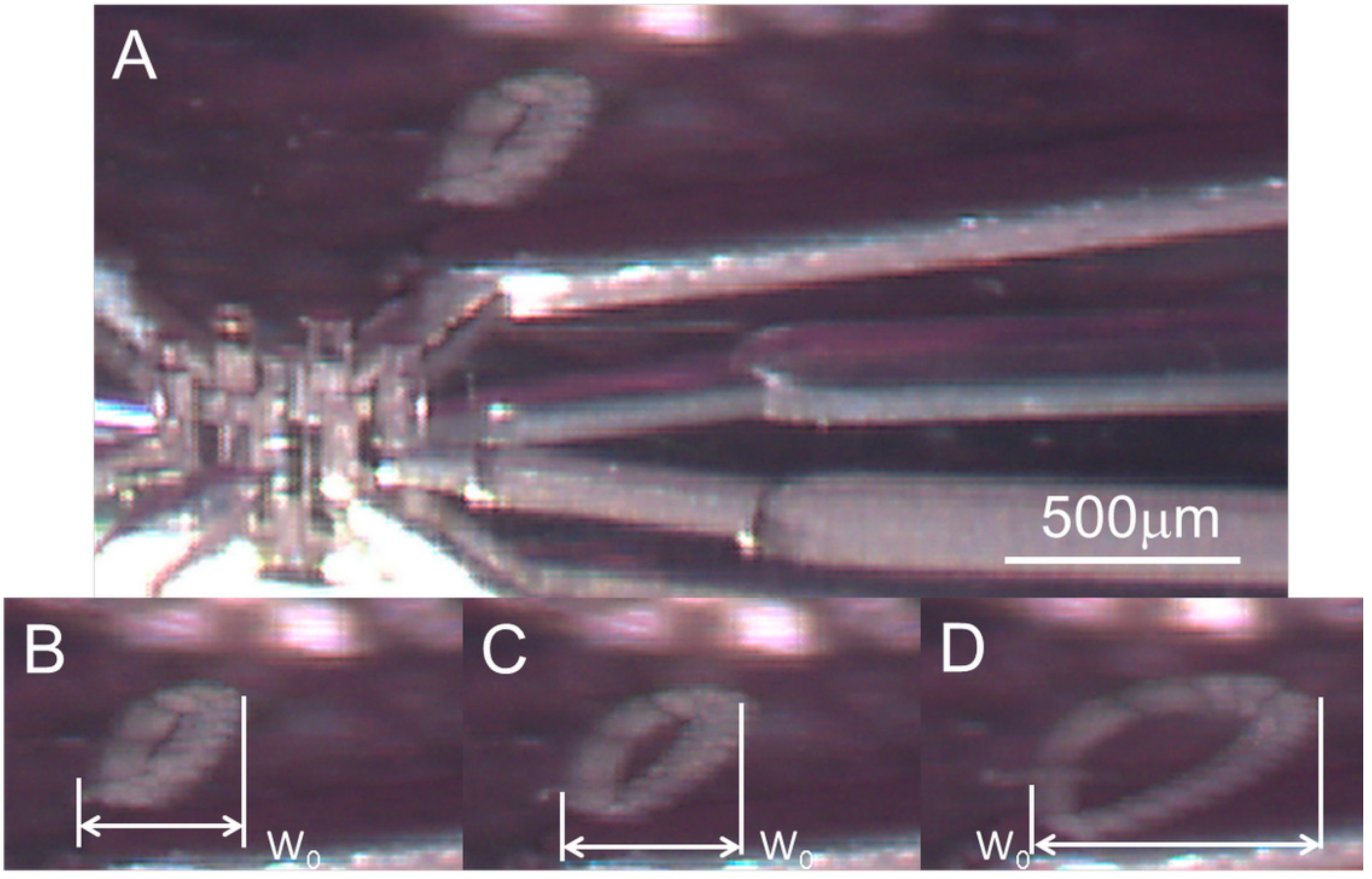
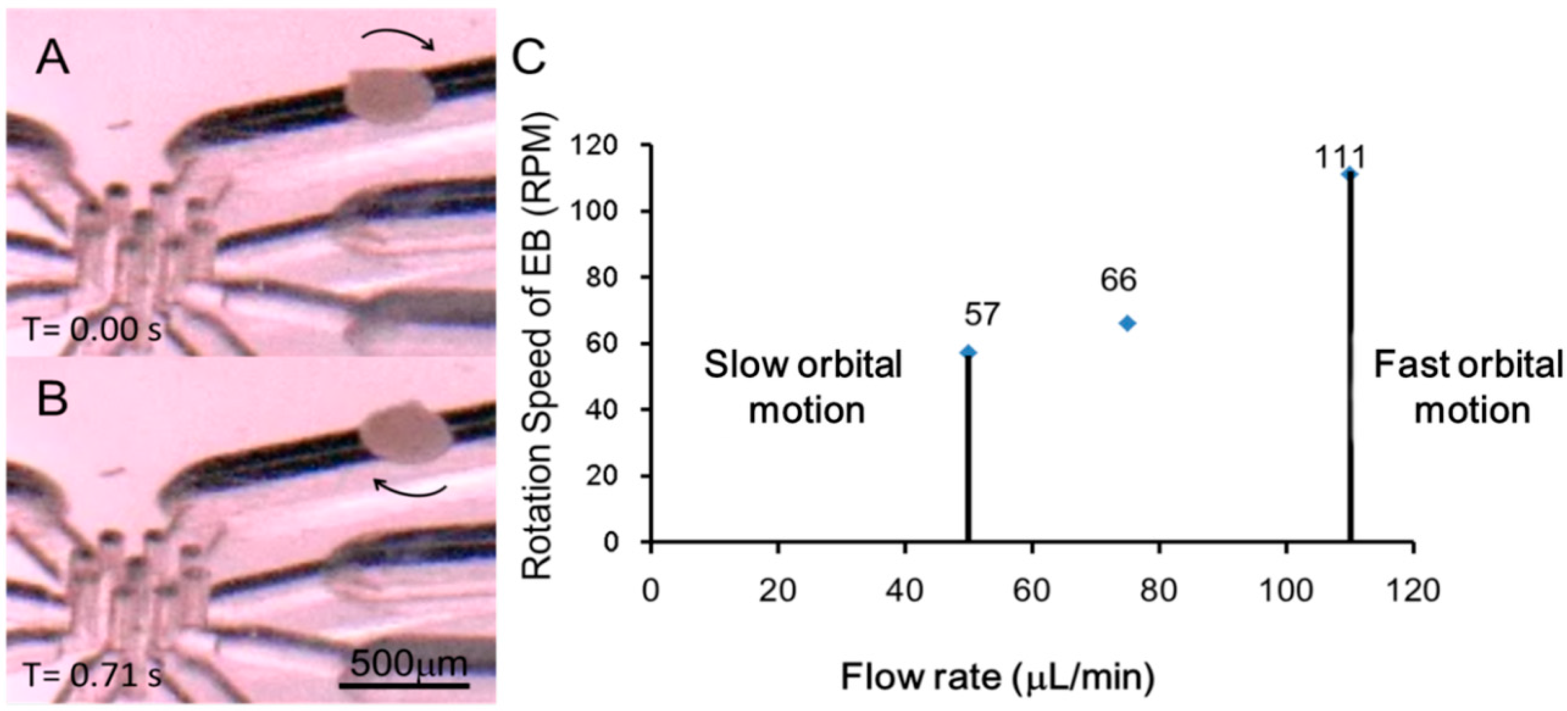
3.3. Self-Rotational Motion of the EB
3.4. Orbital Motion
4. Discussion
4.1. Self-Rotational Motion
4.2. Three-Dimensional Culturing Mode
4.3. Three-Dimensional Flow Stimulation Mode: High-Speed Rotation and Acceleration of Flow
4.4. Three-Dimensional Cell Sorting Mode
4.5. Three-Dimensional Manipulation
4.6. Comparison with Other Methods used in above Applications
5. Conclusions
Supplementary Materials
Acknowledgments
Author Contributions
Conflicts of Interest
References
- Ramalingam, A.V.; Shi, S. Stem Cell Biology and Tissue Engineering in Dental Sciences; Academic Press: Cambridge, MA, USA, 2014; Volume 5. [Google Scholar]
- Haycock, J.W. 3D Cell Culture: A Review of Current Approaches and Techniques. In 3D Cell Culture Methods and Protocol; Humana Press: New York City, NY, USA, 2011; Volume 695. [Google Scholar]
- Xie, Y.; Hardouin, P.; Zhu, Z.; Tang, T.; Dai, K.; Lu, J. Three-dimensional flow perfusion culture system for stem cell proliferation inside the critical-size beta-tricalcium phosphate scaffold. Tissue Eng. 2006, 12, 3535–3543. [Google Scholar] [CrossRef] [PubMed]
- Edmondson, R.; Broglie, J.J.; Adcock, A.F.; Yang, L. Three-dimensional cell culture systems and their applications in drug discovery and cell-based biosensors. Assay Drug Dev. Technol. 2014, 12, 207–218. [Google Scholar] [CrossRef] [PubMed]
- Lee, J.; Cuddihy, M.J.; Kotov, N.A. Three-dimensional cell culture matrices: State of the art. Tissue Eng. Part B Rev. 2008, 14, 61–86. [Google Scholar] [CrossRef] [PubMed]
- Lee, K.Y.; Mooney, D.J. Hydrogels for tissue engineering. Chem. Rev. 2001, 101, 1869–1879. [Google Scholar] [CrossRef] [PubMed]
- Huh, D.; Hamilton, G.A.; Ingber, D.E.; Program, B. From Three-Dimensional Cell Culture to Organs-on-Chips. Trends Cell Biol. 2011, 21, 745–754. [Google Scholar] [CrossRef] [PubMed]
- Choi, N.W.; Cabodi, M.; Held, B.; Gleghorn, J.P.; Bonassar, L.J.; Stroock, A.D. Microfluidic scaffolds for tissue engineering. Nat. Mater. 2007, 6, 908–915. [Google Scholar] [CrossRef] [PubMed]
- Haisler, W.L.; Timm, D.M.; Gage, J.A.; Tseng, H.; Killian, T.C.; Souza, G.R. Three-dimensional cell culturing by magnetic levitation. Nat. Protoc. 2013, 8, 1940–1949. [Google Scholar] [CrossRef] [PubMed]
- Tung, Y.-C.; Hsiao, A.Y.; Allen, S.G.; Torisawa, Y.; Ho, M.; Takayama, S. High-throughput 3D spheroid culture and drug testing using a 384 hanging drop array. Analyst 2011, 136, 473–478. [Google Scholar] [CrossRef] [PubMed]
- Garvin, K.A.; Dalecki, D.; Yousefhussien, M.; Helguera, M.; Hocking, D.C. Spatial patterning of endothelial cells and vascular network formation using ultrasound standing wave fields. J. Acoust. Soc. Am. 2013, 134, 1483–1490. [Google Scholar] [CrossRef] [PubMed]
- Tzima, E.; Del Pozo, M.A.; Shattil, S.J.; Chien, S.; Schwartz, M.A. Activation of integrins in endothelial cells by fluid shear stress mediates Rho-dependent cytoskeletal alignment. EMBO J. 2001, 20, 4639–4647. [Google Scholar] [CrossRef] [PubMed]
- Stolberg, S.; McCloskey, K.E. Can Shear Stress Direct Stem Cell Fate? Biotechnol. Prog. 2009, 25, 10–19. [Google Scholar] [CrossRef] [PubMed]
- Zhang, H.; Dai, S.; Bi, J.; Liu, K.-K. Biomimetic three-dimensional microenvironment for controlling stem cell fate. Interface Focus 2011, 1, 792–803. [Google Scholar] [CrossRef] [PubMed]
- Mach, A.J.; Kim, J.H.; Arshi, A.; Hur, S.C.; Di Carlo, D. Automated cellular sample preparation using a Centrifuge-on-a-Chip. Lab Chip 2011, 11, 2827–2834. [Google Scholar] [CrossRef] [PubMed]
- Hagiwara, M.; Kawahara, T.; Arai, F. Local streamline generation by mechanical oscillation in a microfluidic chip for noncontact cell manipulations. Appl. Phys. Lett. 2012, 101, 074102. [Google Scholar] [CrossRef]
- Lutz, B.R.; Chen, J.; Schwartz, D.T. Hydrodynamic tweezers: 1. Noncontact trapping of single cells using steady streaming microeddies. Anal. Chem. 2006, 78, 5429–5435. [Google Scholar] [CrossRef] [PubMed]
- Tanyeri, M. Hydrodynamic trap for single particles and cells. Appl. Phys. Lett. 2010, 96, 224101. [Google Scholar] [CrossRef] [PubMed]
- Hayakawa, T.; Sakuma, S.; Arai, F. On-chip 3D rotation of oocyte based on a vibration-induced local whirling flow. Microsyst. Nanoeng. 2015, 1, 15001. [Google Scholar] [CrossRef]
- Guo, F.; Mao, Z.; Chen, Y.; Xie, Z.; Lata, J.P.; Li, P.; Ren, L.; Liu, J.; Yang, J.; Dao, M.; et al. Three-dimensional manipulation of single cells using surface acoustic waves. Proc. Natl. Acad. Sci. USA 2016, 113, 1522–1527. [Google Scholar] [CrossRef] [PubMed]
- Yalikun, Y.; Akiyama, Y.; Hoshino, T.; Morishima, K. A Bio-Manipulation Method Based on the Hydrodynamic Force of Multiple Microfluidic Streams. J. Robot. Mechatron. 2013, 1, 611–618. [Google Scholar]
- Yalikun, Y.; Akiyama, Y.; Asano, T.; Morishima, K. System Integration, Modelling, and Simulation for Automation of Multiple Microfluidic Stream Based Bio-manipulation. In Proceedings of the 2014 5th International Conference on Intelligent Systems, Modelling and Simulation, Langkawi, Malaysia, 27–29 January 2014; pp. 209–214.
- Ben Salem, M.; Oesterle, B. A Shear Flow Around a Spinning Sphere: Numerical Study at Moderate Reynolds Numbers. Int. J. Multiph. Flow 1998, 24, 563–585. [Google Scholar] [CrossRef]
- Changfu, Y.; Haiying, Q.; Xuchang, X. Lift force on rotating sphere at low Reynolds numbers and high rotational speeds. Acta Mech. Sin. 2003, 19, 300. [Google Scholar] [CrossRef]
- Ferro, F.; Baheney, C.S.; Spelat, R. Three-Dimensional (3D) Cell Culture Conditions, Present and Future Improvements. Razavi Int. J. Med. 2014, 2, e17803. [Google Scholar] [CrossRef]
- Thomson, J.; Itskovitz-Eldor, J.; Shapiro, S.; Waknitz, M.; Swiergiel, J.; Marshall, V.; Jones, J. Embryonic stem cell lines derived from human blastocysts. Science 1998, 282, 1145–1147. [Google Scholar] [CrossRef] [PubMed]
- Odorico, J.S.; Kaufman, D.S.; Thomson, J.A. Multilineage differentiation from human embryonic stem cell lines. Stem Cells 2001, 19, 193–204. [Google Scholar] [CrossRef] [PubMed]
- Kang, E.; Choi, Y.Y.; Jun, Y.; Chung, B.G.; Lee, S.-H. Development of a multi-layer microfluidic array chip to culture and replate uniform-sized embryoid bodies without manual cell retrieval. Lab Chip 2010, 10, 2651–2654. [Google Scholar] [CrossRef] [PubMed]
- Kim, C.; Lee, K.S.; Bang, J.H.; Kim, Y.E.; Kim, M.-C.; Oh, K.W.; Lee, S.H.; Kang, J.Y. 3-Dimensional cell culture for on-chip differentiation of stem cells in embryoid body. Lab Chip 2011, 11, 874–882. [Google Scholar] [CrossRef] [PubMed]
- Fung, W.-T.; Beyzavi, A.; Abgrall, P.; Nguyen, N.-T.; Li, H.-Y. Microfluidic platform for controlling the differentiation of embryoid bodies. Lab Chip 2009, 9, 2591–2595. [Google Scholar] [CrossRef] [PubMed]
- Lillehoj, P.B.; Tsutsui, H.; Valamehr, B.; Wu, H.; Ho, C.-M. Continuous sorting of heterogeneous-sized embryoid bodies. Lab Chip 2010, 10, 1678–1682. [Google Scholar] [CrossRef] [PubMed]
- Yasuda, S.; Hasegawa, T.; Hosono, T.; Satoh, M.; Watanabe, K.; Ono, K.; Shimizu, S.; Hayakawa, T.; Yamaguchi, T.; Suzuki, K.; et al. AW551984: A novel regulator of cardiomyogenesis in pluripotent embryonic cells. Biochem. J. 2011, 437, 345–355. [Google Scholar] [CrossRef] [PubMed]
- Conway, D.E.; Breckenridge, M.T.; Hinde, E.; Gratton, E.; Chen, C.S.; Schwartz, M.A. Fluid shear stress on endothelial cells modulates mechanical tension across VE-cadherin and PECAM-1. Curr. Biol. 2013, 23, 1024–1030. [Google Scholar] [CrossRef] [PubMed]
- Shelby, J.P.; Chiu, D.T. Controlled rotation of biological micro- and nano-particles in microvortices. Lab Chip 2004, 4, 168–170. [Google Scholar] [CrossRef] [PubMed]
- Chen, Y.; Chung, A.J.; Wu, T.-H.; Teitell, M.A.; Di Carlo, D.; Chiou, P.-Y. Pulsed laser activated cell sorting with three dimensional sheathless inertial focusing. Small 2014, 10, 1746–1751. [Google Scholar] [CrossRef] [PubMed]


| Applications | Environment Situation | Applied Velocity (mm/s) | ||
|---|---|---|---|---|
| Other Methods | This Paper | Other Methods * | This Paper | |
| EB Culturing | Closed | Open | 0.127 [28]–3 [29] | Up to 2.217 |
| EB Stimulation | Closed | Open | 0.833–3 [30] | Up to 15.4 |
| EB Sorting | Closed | Open | 0.383 [31] | Up to 15.4 |
| EB Manipulation | Closed | Open | 0.383 [31] | Up to 2.217 |
© 2016 by the authors. Licensee MDPI, Basel, Switzerland. This article is an open access article distributed under the terms and conditions of the Creative Commons Attribution (CC-BY) license ( http://creativecommons.org/licenses/by/4.0/).
Share and Cite
Yalikun, Y.; Kanda, Y.; Morishima, K. A Method of Three-Dimensional Micro-Rotational Flow Generation for Biological Applications. Micromachines 2016, 7, 140. https://doi.org/10.3390/mi7080140
Yalikun Y, Kanda Y, Morishima K. A Method of Three-Dimensional Micro-Rotational Flow Generation for Biological Applications. Micromachines. 2016; 7(8):140. https://doi.org/10.3390/mi7080140
Chicago/Turabian StyleYalikun, Yaxiaer, Yasunari Kanda, and Keisuke Morishima. 2016. "A Method of Three-Dimensional Micro-Rotational Flow Generation for Biological Applications" Micromachines 7, no. 8: 140. https://doi.org/10.3390/mi7080140