1. Introduction
The ongoing trend towards miniaturization of electronics with proliferation of functionality and performance requires compact and efficient power management at microsystem platforms. The aforementioned aspects are addressed by the power semiconductor industries and various research groups through their ability to deliver advanced processing and functional integration by driving the power management system in the very high frequency regime (VHF, 30 to 300 MHz) [
1]. A major challenge is that the further miniaturization of the power modules is limited by the presence of bulky inductive components though the inductance needed at the VHF frequencies are relatively low compared to the systems operating at lower frequencies [
2,
3].
Typically, inductive components at VHF regime are implemented using bulky air core devices. The size of the inductors can be reduced by integrating soft magnetic cores to achieve a high inductance density, however, at VHF regime the frequency dependent core losses become dominant [
4]. Advanced but expensive, multilayer deposition techniques such as electroplating or sputtering are usually adopted to minimize the losses [
5,
6,
7,
8]. However, the process complexity remains as an impediment [
9,
10].
An alternative method is to utilize a composite material comprising metallic magnetic powder separated by a dielectric polymer to increase the inductive device performance for high frequency applications [
11]. The dielectric guarantees high electrical resistivity of the core, while the metal grains are too small for significant eddy currents to circulate within the particles, which results in lower losses in the VHF regime. Through careful adjustment of the magnetic permeability on the one hand, and the particle size and shape on the other hand, one can tailor the magnetic response of the core to a specific need. Being a promising technique, it still has various disadvantages for example it is difficult to integrate it into a complementary metal-oxide-semiconductor (CMOS) process since most of the reported fabrication methods involve high temperature sintering and annealing of the magnetic cores [
12].
In our approach, these limitations are addressed with the help of an improved epoxy based binder material and a new casting technique integrated with an automated wirebonding process for wafer-level batch fabrication of polymer magnetic composite (PMC) core microcoils and microtransformers. The fabrication of 3D microcoils using an automatic ball-wedge wirebonder was well established in the previous works in our laboratory [
13]. So far we fabricated air core and laminated Metglas
® 2714 (Metglas Inc., Conway, SC, USA) based magnetic core inductive components [
14,
15,
16]. The proposed extremely versatile methodology in this paper allows us to integrate PMC cores with different magnetic powders and varying cross section, that could result in an inductive component having a moderate inductance density but can be used at the VHF regime with low core losses. This is a straight forward and cost effective approach while it enables reproduction of such magnetic cores in a normal lab space. In this paper, we report a versatile fabrication process to structure cylindrical PMC cores with varying magnetic proportion. The PMC is made out of a high permeability NiFeZn based soft magnetic powder and Araldite based epoxy as the binding dielectric material. The well established wirebonding technique was used to fabricate inductor and transformer chips. The frequency dependent magnetic behavior of the fabricated passive components is compared to the previously reported devices. We also introduce a process for the encapsulation of the fabricated devices with an epoxy based magnetic composite.
2. Choice of Core Materials
One of the critical considerations in fabricating PMC cores is the material choice. The polymer binder and the soft magnetic powder determines the viability of the fabrication process and the magnetic behavior of the inductive component, respectively.
2.1. Soft Magnetic Powders
The main parameter, often used as a figure of merit for soft magnetic materials, is the relative permeability (
), which is a measure for the response of the material to the applied magnetic field. In our case, an appropriate material for the magnetic cores needs to have a high permeability, a high electrical resistivity, and a low coercivity. Pure iron is the most prototypical soft magnetic material. It has a very high saturation flux density and a high permeability but a low resistivity which results in high core losses. However, alloyed iron provides higher magnetic permeability and is expected to provide lower core losses when used as amorphous magnetic ribbon or magnetic powder [
17,
18], therefore it is a better choice for fabricating composite core devices with high efficiency.
In addition, particle shape and size further influence the eddy current losses and coercivity, thereby, the overall frequency dependent magnetic response of the core [
18,
19]. These factors depend on the preparation and processing methods of the magnetic alloy powders [
20]. Mechanical alloying [
21] and borohydride reduction of salt solution containing Fe, Co, and Nd [
22] are commonly used for the synthesis of amorphous and partially crystalline magnetic powders.
A brief overview on the available magnetic alloy powders is reported in this section to conclude the choice of a magnetic material.
Fe-Si alloys are harder and have a higher electrical resistivity than pure iron [
23]. For applications requiring a very low hysteresis loss, high permeability, low remanence, and freedom from magnetic aging,
Fe-Si alloys are an optimal choice.
Fe-Co alloys have the highest magnetization saturation of all known magnetic alloys [
24].
Fe-Ni alloys possess the highest permeability of all the soft magnetic alloy [
18]. Therefore, these alloys are considered foremost for our application that requires high permeability. In this work, CMD5005, an NiFeZn based soft magnetic powder from the National Magnetics Group was used. The powder is expected to provide a high permeability and a high electrical resistivity at the VHF frequency regime. The properties are listed in
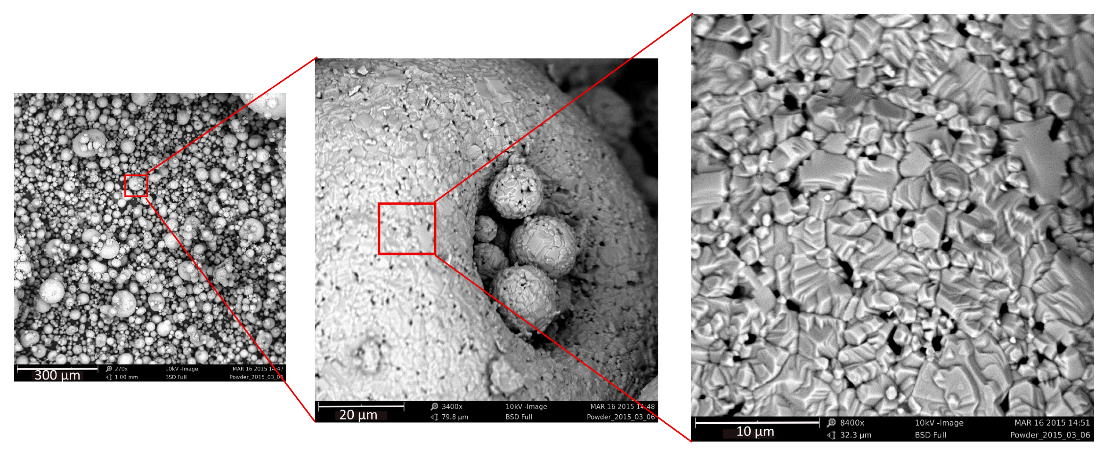
Table 1. SEM images of the powder are shown in
Figure 1.
2.2. Polymer Matrix
One of the main objectives of this work was to insulate the magnetic particles from each other with an insulating dielectric polymer. The binding material should have a low dielectric constant and provide viability for mixing a high percentage of magnetic powder. It should also ensure sufficient adhesion to the substrate to withstand mechanical, thermal, and chemical impacts employed during the fabrication process. In addition, the binder material should have a low viscosity, a high glass transition temperature (
), long pot time (the time it takes to double the initially mixed viscosity), low curing temperature, and a high Young’s modulus. Based on the study of various publications [
23,
24,
26,
27,
28,
29,
30,
31,
32] and intensive search for commercial availability, suitable polymers have been identified which are listed in
Table 2.
For our fabrication process, two component epoxies seemed to be a viable option since there are wide varieties of such epoxies with low viscosity and optimal pot time (from 25 to 60 min), hence, they can be processed with a minimal effort. Though the commonly available, room temperature curing Araldite 2011 epoxy (Huntsman Advanced Materials GmbH, Basel, Switzerland), resulted in rigid structures on the FR4 substrate, the
of the cured structure was not sufficient to withstand the temperature applied during the wirebonding process. On the other hand, thermal curing two component epoxies AW4510 + HW4510 and AW4804 + HW4804 from Huntsman Advanced Materials have a high
once cured, however, they showed poor adhesion to the FR4 substrate. Hence an unconventional mixture of AW4510 + HW4804 was prepared. The result was promising since the adhesion to the substrate and the
were improved. The optimal curing conditions reported in
Table 3 were found by trial and error. The automated wirebonding process showed that the final structures made with this new epoxy mixture were stable up to 150
C.
3. Chip Design
In addition to the material choice, the geometrical design and the substrate material of the chip also affects the inductive device performance. Generally, the core shape will be straight cylindrical (open-loop), or closed-loop (square, rectangular, or toroidal) to fully guide the magnetic flux. Our solenoidal 3-D coil approach thereby allows to minimize the footprint of the chip without compromising the electrical performance.
The dimension of the PMC core determines the geometry of the solenoid coil that influences the inductance of the coil, thereby the frequency dependent properties of the component.
The self-demagnetization of a magnetic core is another important factor, because it strongly influences the properties and behavior of the core irrespective of the material that it is made of. It increases with the increasing aspect ratio of an open-loop core. Therefore, the core height was chosen to be 2 mm in order to minimize the self-demagnetization for our cores with diameter of 1 mm,
i.e., a footprint of 0.79 mm
. The diameter of 1 mm is the least diameter that our casting method could achieve. Also, having post of higher than 2 mm is not applicable as it interferes with the wirebonding fabrication technique. The demagnetizing factor (
) of a cylindrical core having an aspect ratio of 0.5 is 0.18 (in the
z direction) and is given by the Equation (1) [
33]:
where
n is the ratio of diameter and height,
i.e., the aspect ratio.
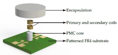
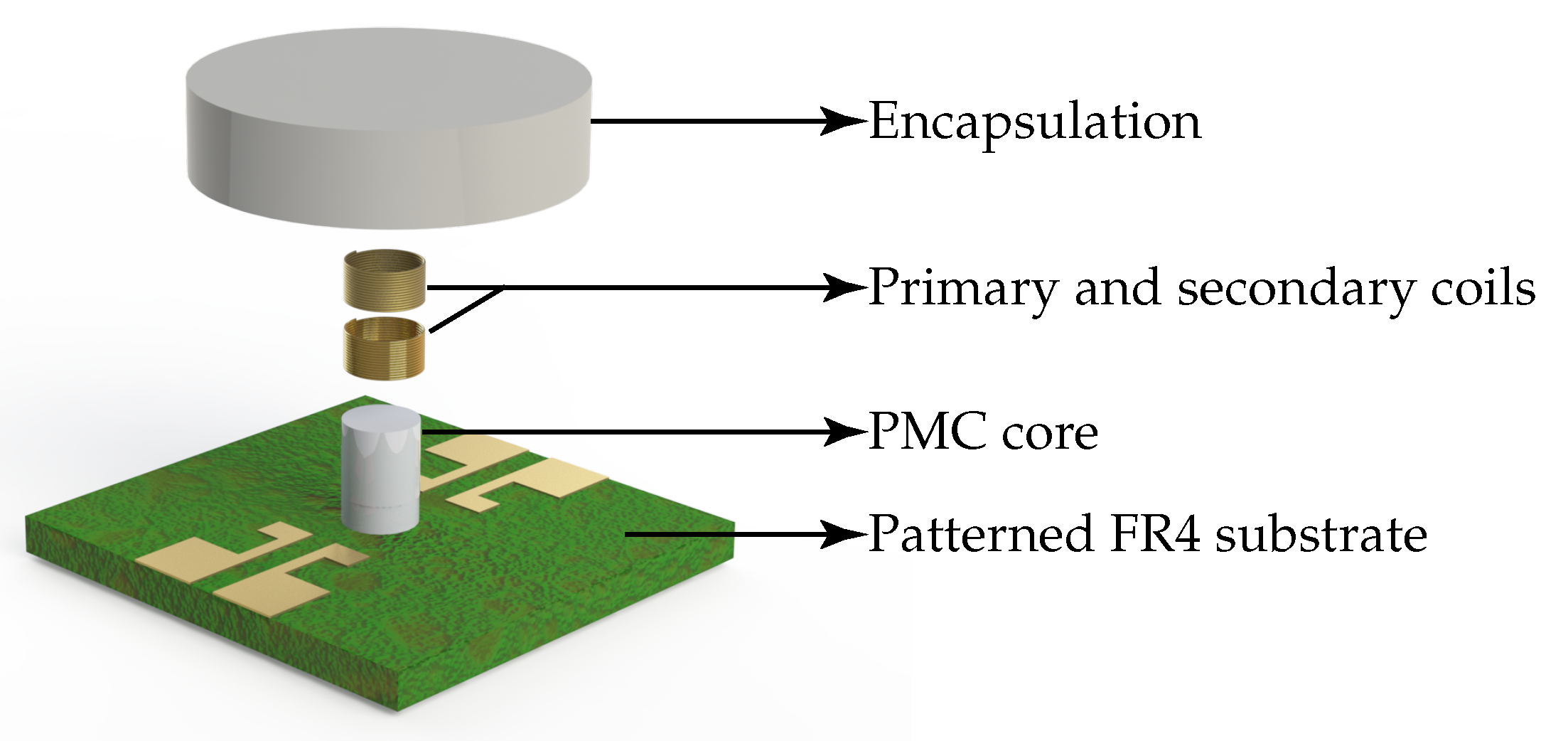
Later, after the coil winding, the core can be encapsulated with the same magnetic composite material as shown in
Figure 2. The encapsulation provides self shielding, mechanical stability, and eases the handling of the chips. As a substrate we chose a 0.5 mm thick FR4 from Bungard Elektronik GmbH (Windeck, Germany). This material is expected to have a low substrate induced losses compared, for example, to silicon due to the high insulation of the substrate material. It also provides optimal temperature resistance, good adhesion to mostly available epoxies, and sufficient stiffness for the automated wirebonding.
4. Fabrication
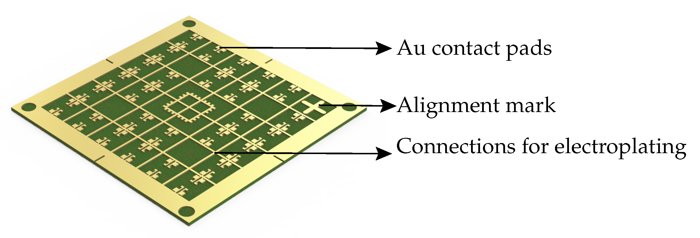
The finalized fabrication process involved simple and cost effective steps. No cleanroom processes were needed, neither for the fabrication of the polymer magnetic cores nor for the fabrication of the inductive coils. The process involved patterning of the 500 µm thick FR4 substrate (dimension: 50 mm × 50 mm) having a 35 µm thick copper layer. Subsequently, the substrate had to be electroplated with 3 µm Au. A 1 µm thick Ni layer was deposited as an intermediate layer to improve the adhesion between copper and gold. The schematic of the Au patterned plated substrate is shown in
Figure 3. Then, to disconnect the conductive tracks between the pads which were necessary for the electroplating and to support the final dicing of the fabricated chips, trenches were cut into the substrate using a CNC-mill to a depth of 100 µm as shown in
Figure 4a.
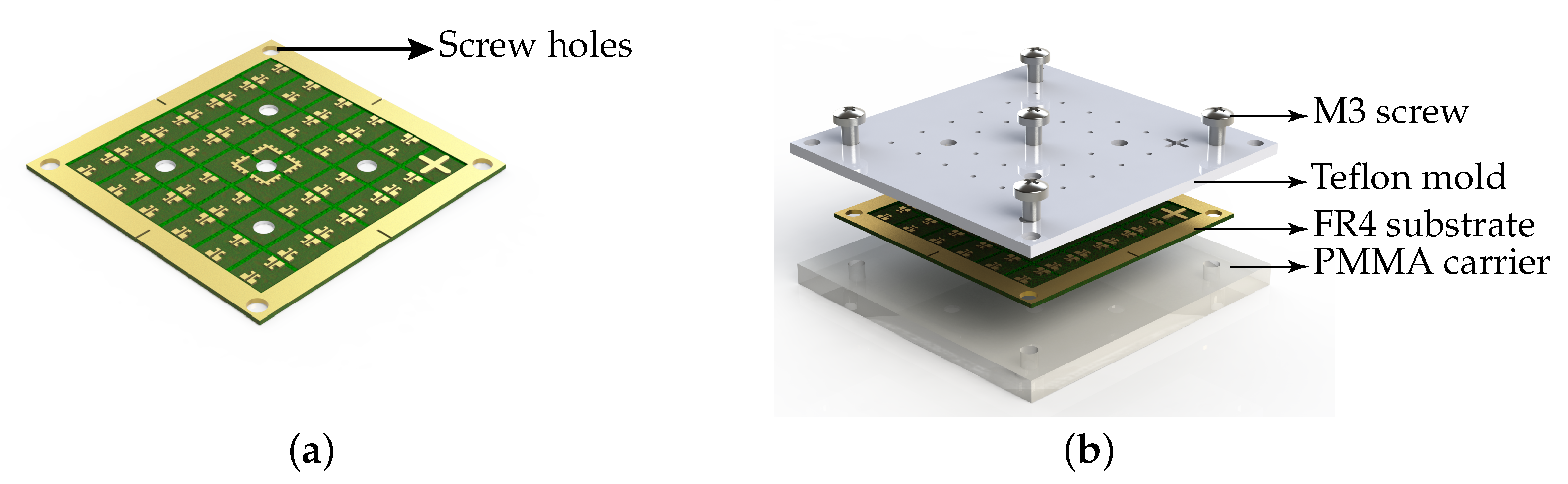
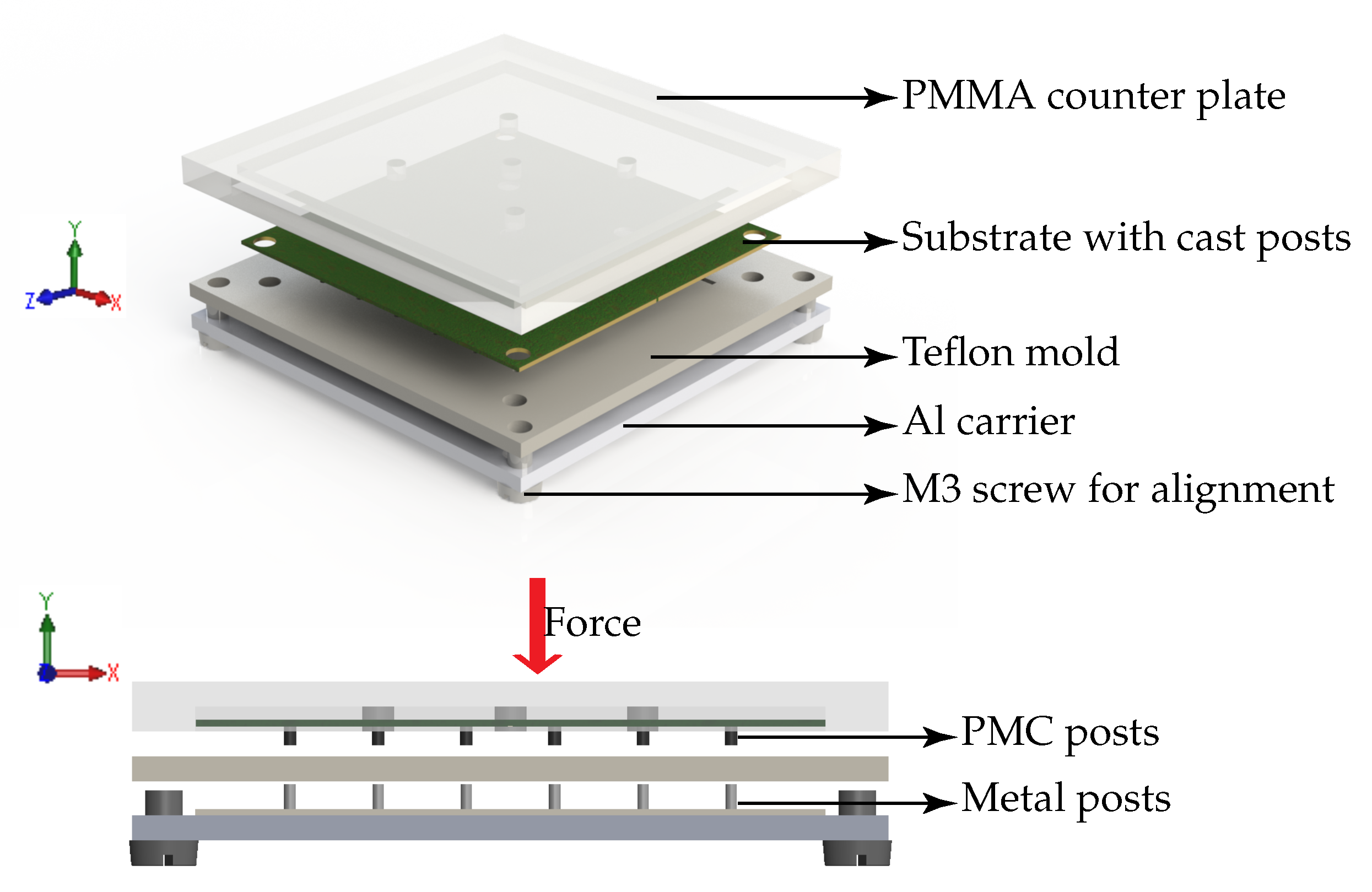
The next step was to prepare a mold and clamping carrier for the casting process. Teflon was chosen as the mold material because of its low surface energy due to which it shows low adhesion to most epoxies and polymers. In this work 2 mm thick PTFE sheets from Polymer-Akzent GmbH were used to fabricate the teflon mold. For the clamping carrier 4 mm thick PMMA was chosen in order to allow for visual alignment of the mold and the FR4 substrate. A CNC machine (4030, ISEL) was used to structure both the teflon mold and the PMMA carrier. Once the mold and the carrier were screwed together, the PMC posts could be cast into the clamped substrate and cured. The exploded view of the clamped assembly to cast the PMC is shown in
Figure 4b.
The demolding of the PMC posts from the substrate was one of the crucial steps since the posts could be damaged. Thus, the demolding was facilitated by an additional plate with metal posts and a PMMA counter plate. When aligned with the mold they are used to push the PMC posts out of the mold without any damage as depicted in the
Figure 5. Once the PMC posts were made, the following steps were to wind the solenoid coil using an automated wirebonder and then to encapsulate the device.
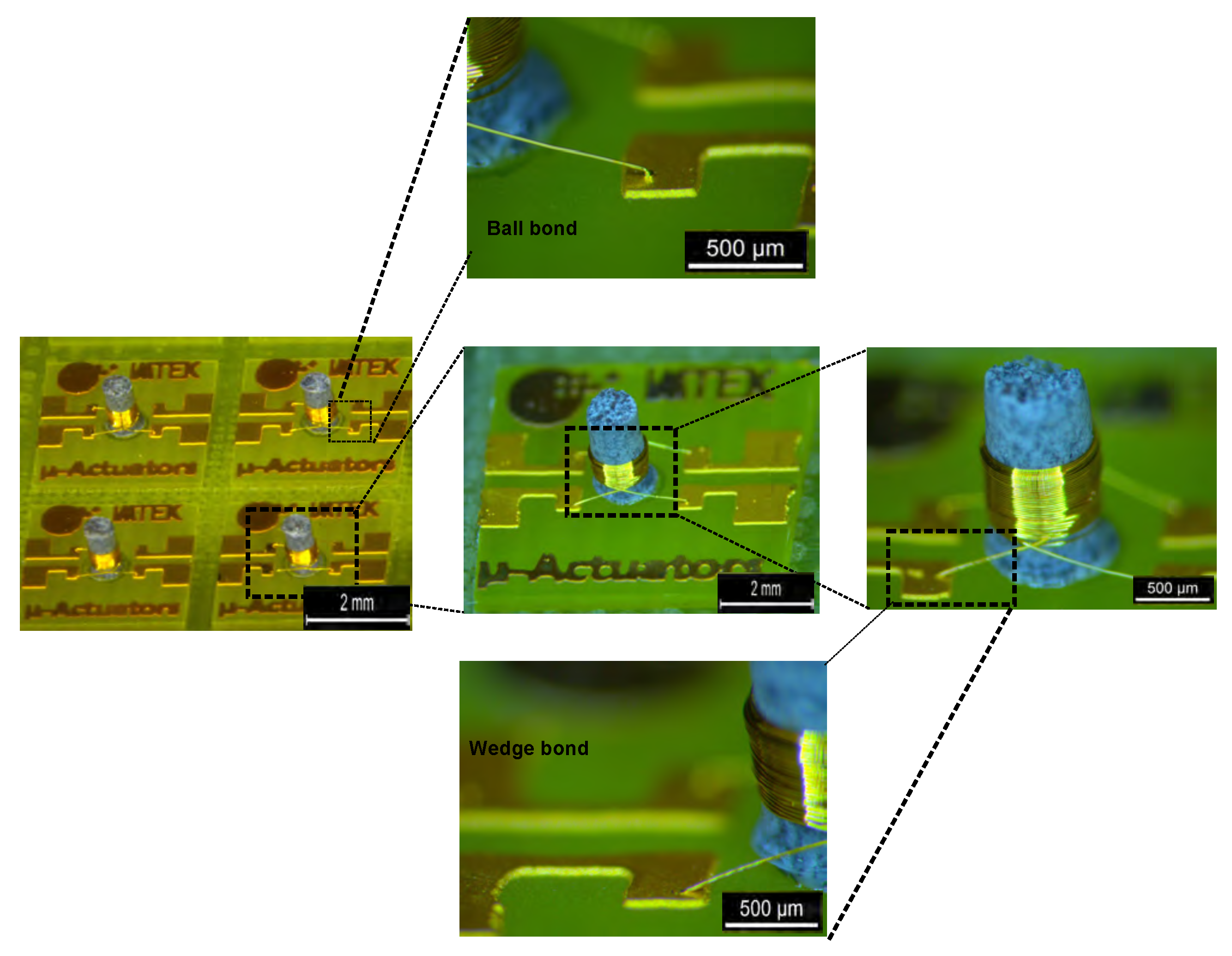
The wirebonding process was done using a WB3100 (ESEC, Cham, Switzerland) wirebonder. Within 10 s , each coil was wound with up to 60 turns of insulated 25 µm thick gold wire. This winding technique was already well established in the previous works in our laboratory [
11,
13,
16]. However, the bonding parameters such as temperature, ultra-sound power, and pre and process forces for both wedge and ball bonds were determined. These parameters provided successful bonding on the 500 µm thick FR4 substrate.
PMC cores made out of a mixture of 45%–65% CMD5005 powder with an Araldite AW4510 + HW4804 epoxy were fabricated. The curing conditions for various compositions are listed in the
Table 3. Inductor and transformer chips were made with coils having varying number of turns wound on the PMC cores. A microscopic image of the transformers is shown in
Figure 6.
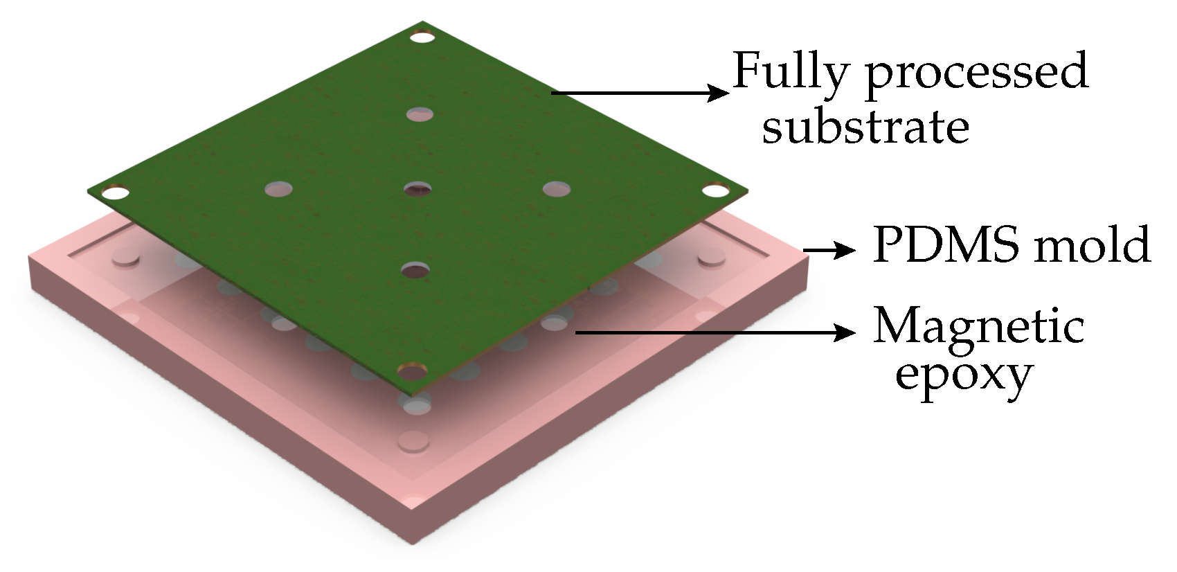
The last and optional process step is the encapsulation of the chips. The encapsulation involved preparation of a PDMS mold in which the encapsulation material was cast, as shown in
Figure 7.
The immersed wirebonded posts were cured at 100 C for one hour on a hot plate. Once cured, the PDMS mold was peeled off. The encapsulation material can be chosen for the required performance. For instance, if a magnetic composite is used as encapsulation material, the inductive chip has a higher inductance density than the chip with a non-magnetic encapsulation. However, it compromises the frequency of operation and the electrical performance, due to the addition of a dielectric material and the core induced parasitic losses.
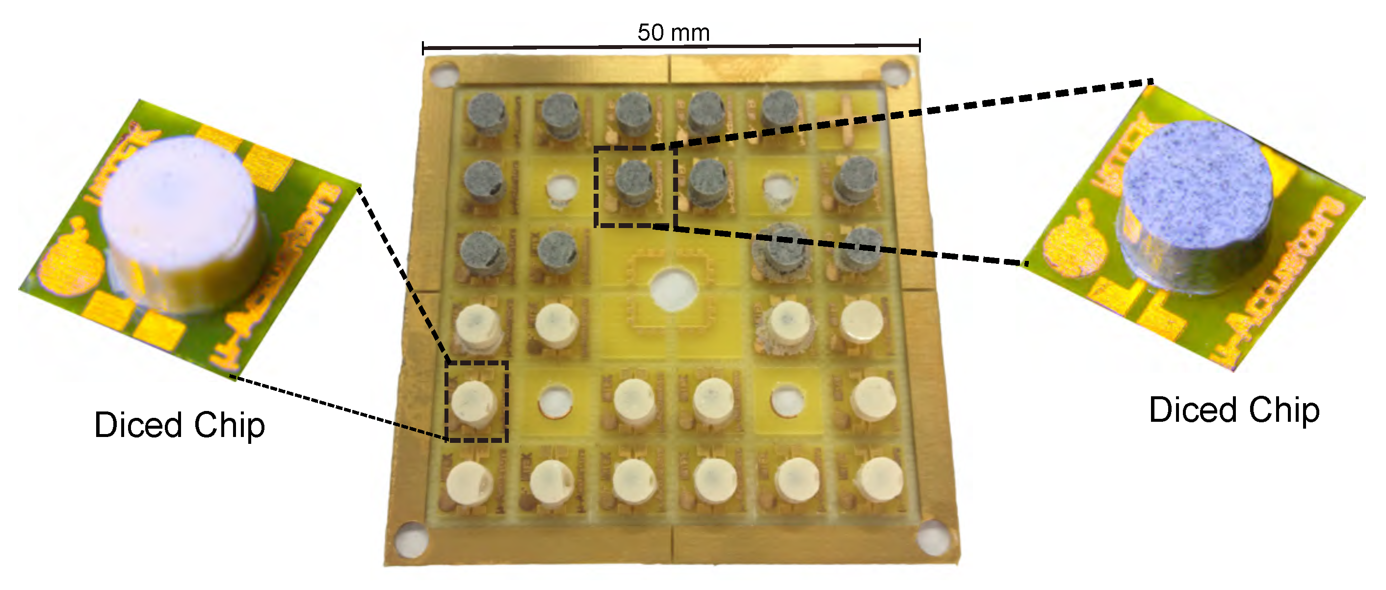
The chips were diced by using a conventional scissor. The milling step which was done prior to the casting process ensures the ease of the dicing step without any damage to the chips. A fully processed substrate having chips with magnetic as well as non-magnetic encapsulation is shown in
Figure 8.
5. Measurements and Results
The inductance of a solenoidal coil wound around a magnetic core is directly proportional to the magnetic permeability of the core. Typically, by increasing the magnetic powder percentage the relative magnetic permeability of the PMC core can be increased. However, the highest permeability does not necessarily lead to an optimal performance at the VHF regime [
34]. In the PMC cores, two kinds of eddy current losses can be identified, one due to the current circulating within the insulated magnetic particles and the other due to the current around the clusters of particles. With an increasing powder percentage the cluster formation becomes more likely which does not only enhance electrical losses but, besides, will also affect the mechanical stability of the cores. Therefore, the expected optimal percentage to attain the optimal permeability of magnetic powder in the composite has to be determined.
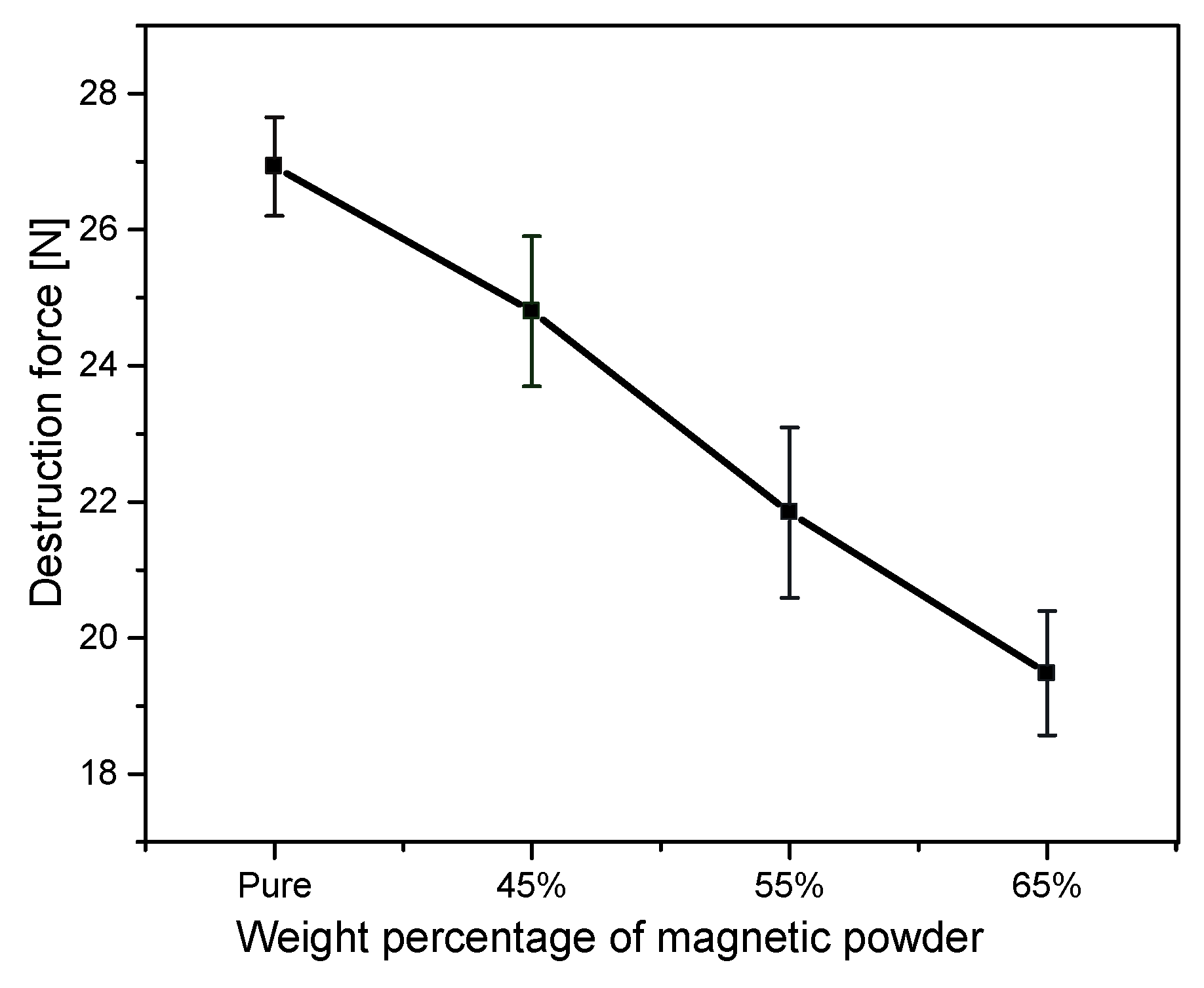
5.1. Mechanical Characterization of PMC Cores
The mechanical strength was evaluated using a multipurpose bond tester (Dage 4000, Nordson, Buckinghamshire, UK) to characterize the adhesion of the composite cores to the FR4 substrate. The results of the measurement depicted in
Figure 9 show the degradation of the adhesion of the posts to the FR4 substrate with respect to the weight percentage of the magnetic powder in the core composite. The destruction force is the force required to tear of the posts from the substrate at a room temperature of 25
C. For the samples made with a percentage higher than 75% the posts showed poor stability.
5.2. Electrical Characterization
The high frequency characterization was performed using an impedance analyzer (E4991A, Agilent Technologies, Santa Clara, CA, USA) in the case of the inductor chips or a vector network analyzer (E5071A, Agilent Technologies) in the case of the transformer chips. A probe-station (9000, Cascade Microtech, Beaverton, OR, USA), equipped with two microprobes (SG/GS-500, Cascade Microtech) was used for the mounting and the measurement. Prior to the measurements, open, short, load, and through (OSLT) calibrations were done and verified using an impedance standard substrate (ISS) (106-683, Cascade Microtech). The measurement was done for the frequency range of 1 MHz to 1 GHz having 801 measurement points.
5.2.1. Inductor Characteristic
The purpose of the inductor characterization was to analyze the influence of the PMC cores and to determine the optimal percentage of the magnetic powder in the composite to achieve both a high inductance and a highest possible quality factor at the VHF frequency range. By extracting the real and the imaginary parts of the impedance, the inductance, electrical resistance, and quality factor of the coils were determined by using the following equations:
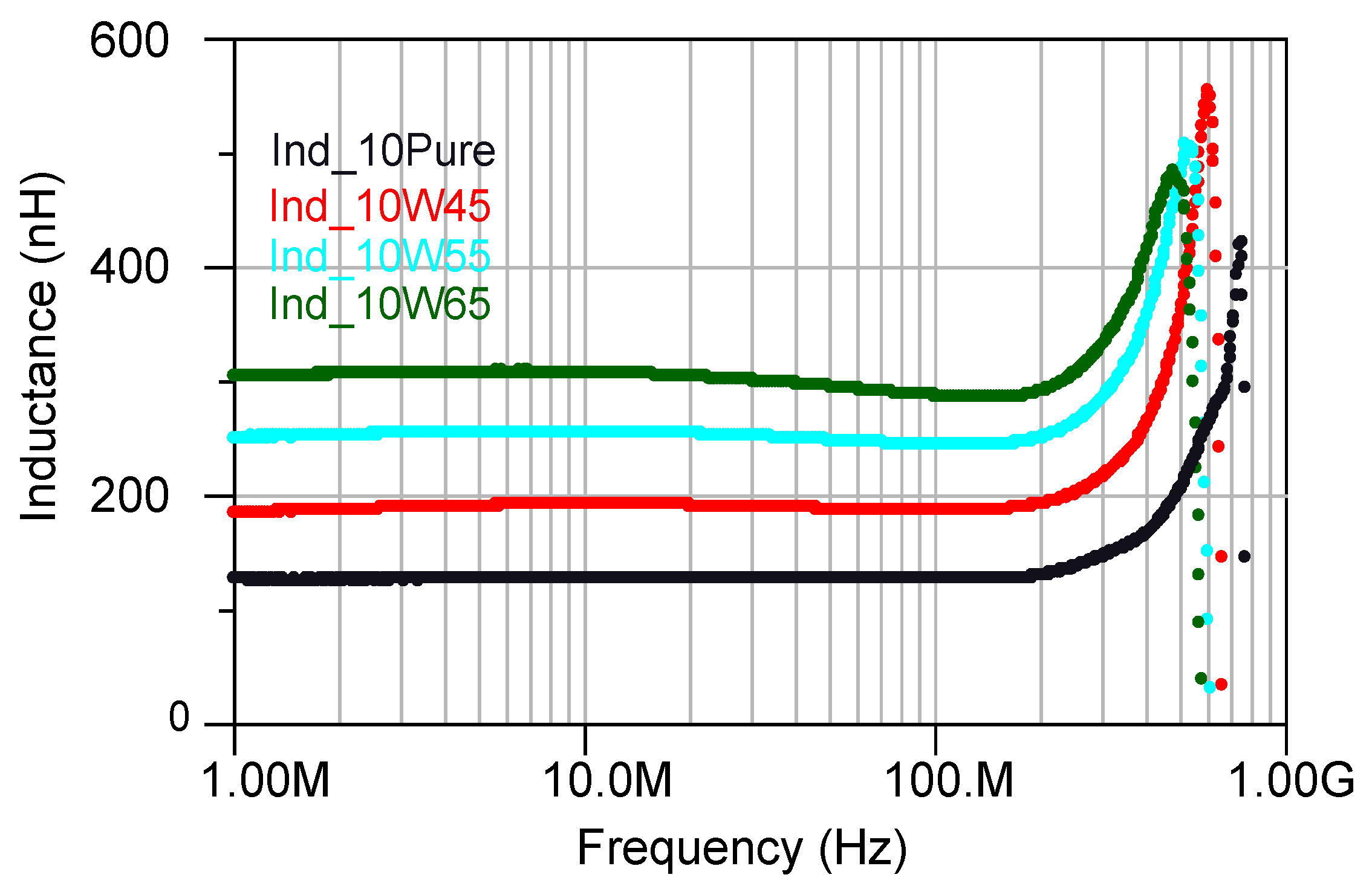
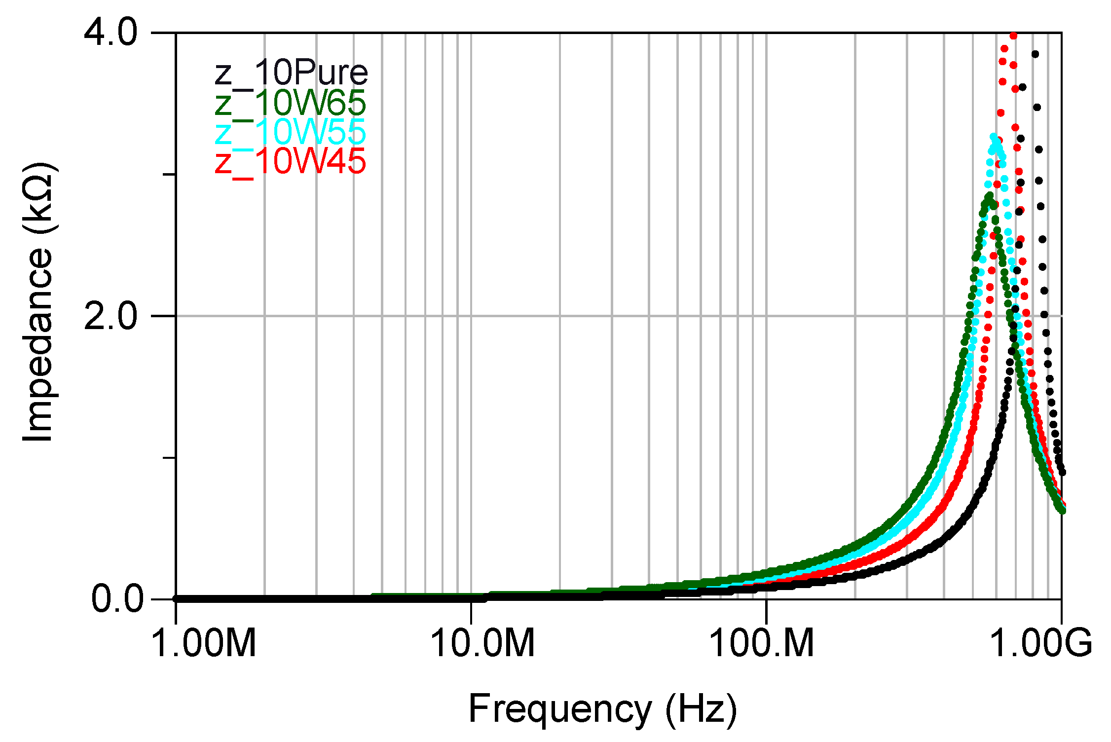
Impedance of the inductors with 10 turns having cores with a different percentage of the magnetic powder have been depicted in
Figure 10. For the inductors with a higher percentage of the magnetic powder, the impedance started to increase at a lower frequency due to the added core losses in the inductors. Furthermore, the inductance increased with increasing percentage of the magnetic powder as it is shown in
Figure 11. However, increasing the inductance caused the self resonance frequency (SRF) to decrease (
Figure 10), as described through:
where
is the parasitic capacitance.
The presence of the magnetic core introduces new losses that compromises the quality factor as in obvious from
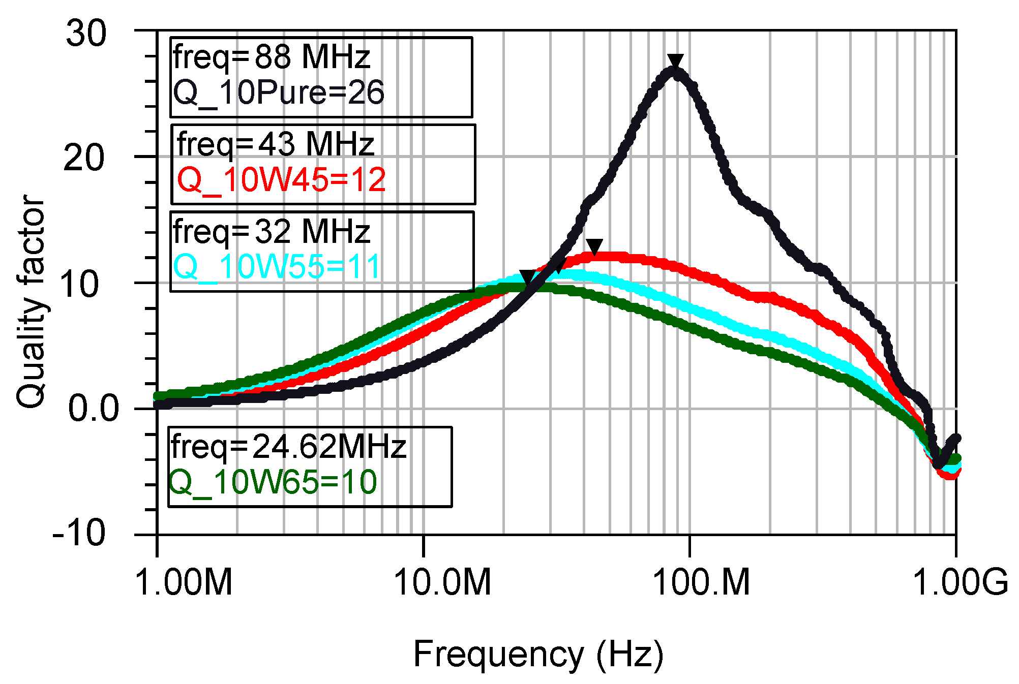
Figure 12, where the cores with 45% magnetic powder show a slightly higher quality factor than the core with 65%.
In order to study the influence of the number of turns, coils with a varying number of turns (7, 10, 15, 20, 30) were wound on the posts made out of different magnetic composites.
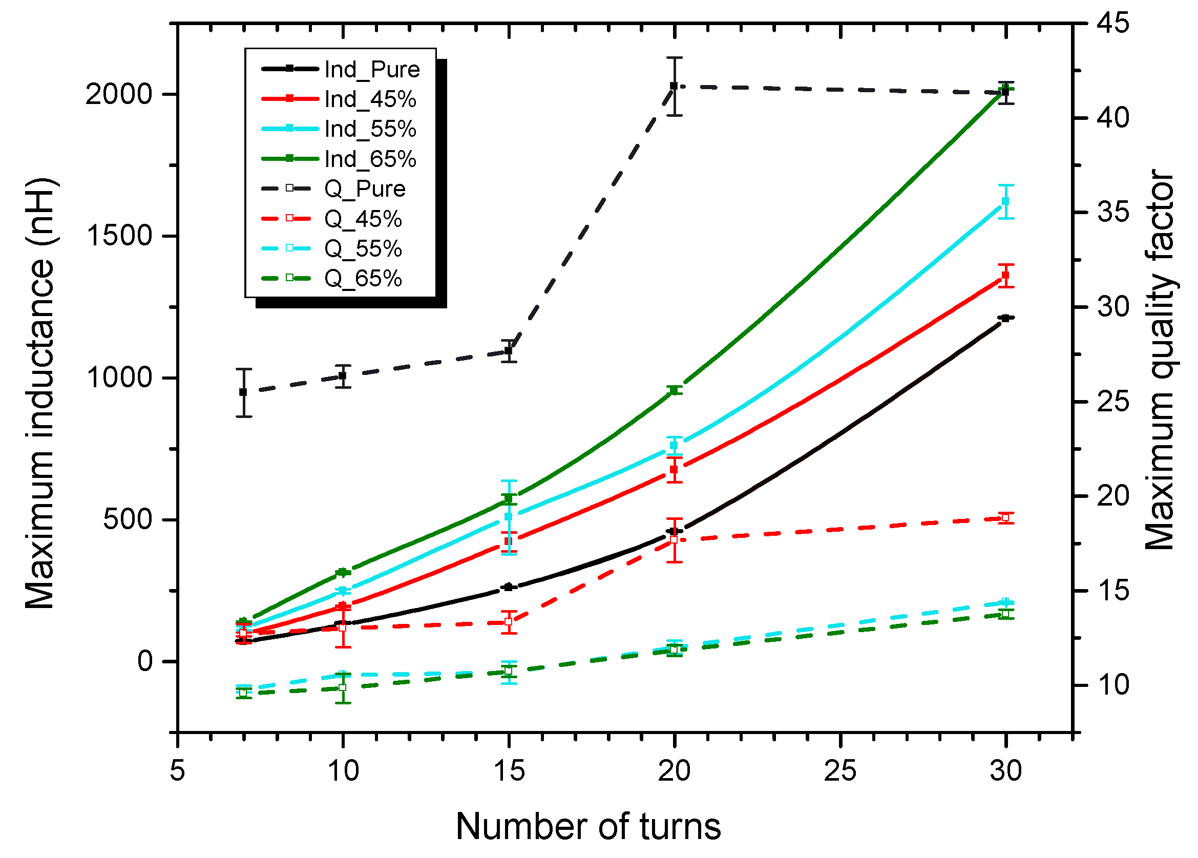
Figure 13 shows the measured maximum inductance (
) and quality factor (
) as a function of the number of turns for varying percentage of magnetic powder. The error bars show the deviations of 5 measured similar chips. From this graph we can visualize the trade off between the inductance and quality factor which guides us to a better choice of inductor.
Both the maximum inductance (
) and maximum quality factor (
) increase with the increase in number of turns. However, the DC resistance inherently increases with the increase in number of turns and also affects the
. This can be visualized by considering the (
) value data points at 20 and 30 number of turns. The inductor with 65% magnetic powder provides higher
than the core with 55% magnetic powder at a cost of a slightly smaller
. Further more the effective permeability of the core can be considered. The inductance of a coil is only a function of its geometry and the permeability of the core and its surrounding medium [
16]. For a fixed number of turns, both the pure epoxy core and the magnetic core coils are geometrically identical, hence, we can consider the inductance ratio of a PMC core to the pure epoxy core as the effective permeability
of the PMC core. The PMC cores with 65% magnetic powder thus showed the highest effective permeability value of 2.4 among all the other PMC cores.
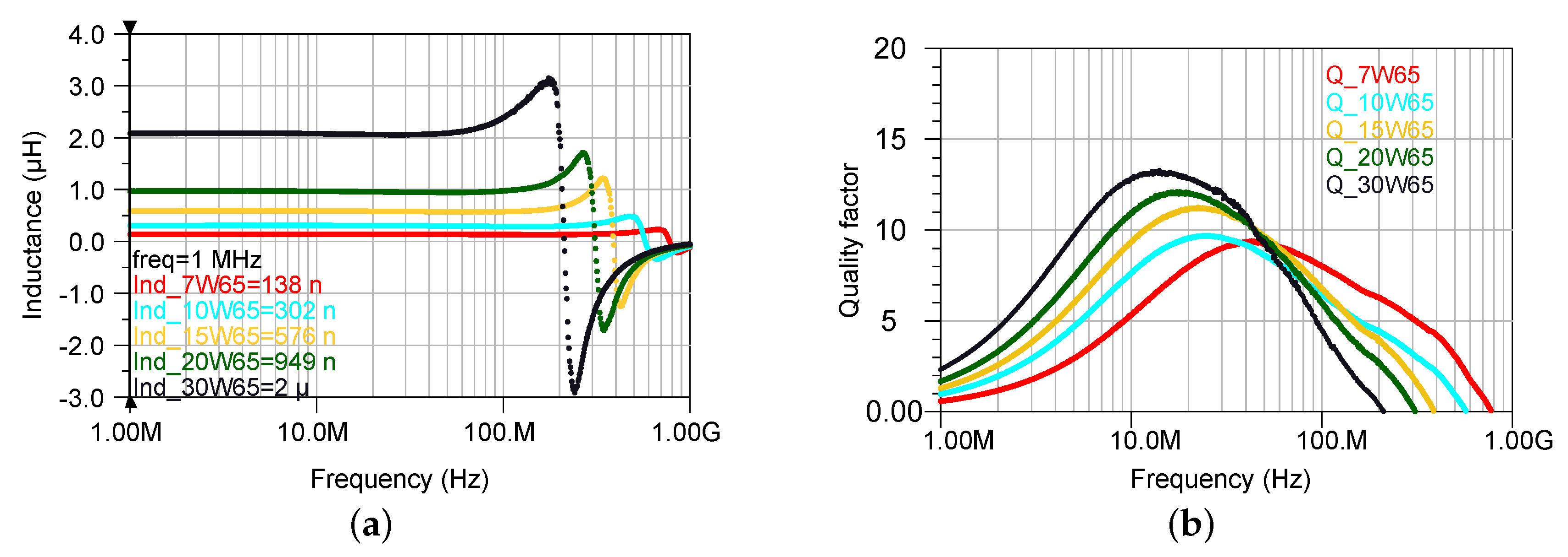
The graphs shown in
Figure 14 show the achieved inductance and the quality factor of the PMC cores with 65% magnetic powder for the measured frequency range . The maximum inductance of about 2 µH is achieved for the sample having 30 turns. It shows a constant inductance with a rapid increase near the resonance occurring at 200 MHz. The maximum quality factor of the inductor is 13 at 14 MHz. The values which were achieved here are compared to the previously reported wirebonded microcoils which are listed in
Table 4.
5.2.2. Transformer Characteristics
The next objective was to implement transformer chips using coils on PMC cores with 65% magnetic powder and to study the effect of encapsulation with a magnetic epoxy. The flux linkage in a transformer can be defined as a fraction of the total possible flux linkage between the coils. This fractional value is called the coefficient of coupling or coupling factor and is represented by the letter κ, generally expressed as a fractional number between 0 and 1 or a percentage (%) value. It can be calculated from the impedance values by the following equation:
The efficiency (η) of a transformer is given by the ratio between the output power and input power. It can be calculated directly from the S-Parameters by using the following equation [
36]:
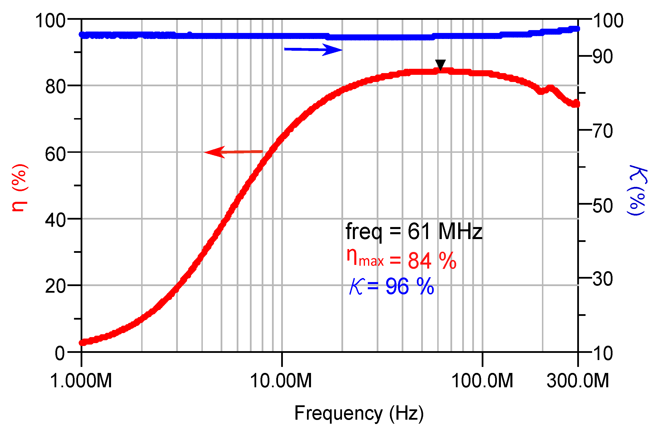
A transformer with 10 turns having a turn ratio of 1:1, wirebonded on PMC cores made out of 65% magnetic composite, was characterized. The measured frequency dependent coupling factor and efficiency of the transformer are shown in
Figure 15.
The transformer showed inductance values of 277 nH (primary coil) and 270 nH (secondary coil), and the self resonance frequency was at 419 MHz. The coupling capacitance between the primary and secondary windings of the transformer was 2.35 pF. The measured coupling factor was 96%. Therefore, the magnetic inductance
as well as the leakage inductance
for the primary coil of the transformer were calculated to be 266 nH and 11 nH, respectively. The efficiency increases with increasing frequency until the losses in the conductor become dominant. The maximum efficiency reached a new value of 84% at 61 MHz.
Table 5 proves the high performance of the PMC core microtransformers in terms of the coupling factor and efficiency as well as the small geometrical size of the chips. All the devices except the ones which marked with (*) were characterized using 50 Ω load.
5.3. Effect of Encapsulation
The fabricated transformers with 10 turns were encapsulated with the magnetic epoxy in order to visualize the effect of encapsulation. The magnetic encapsulating epoxy was made out of AW4510 based epoxy mixed with 20% of the NiFeZn magnetic powder. The measured frequency dependent coupling factor and efficiency of the encapsulated transformer is shown in
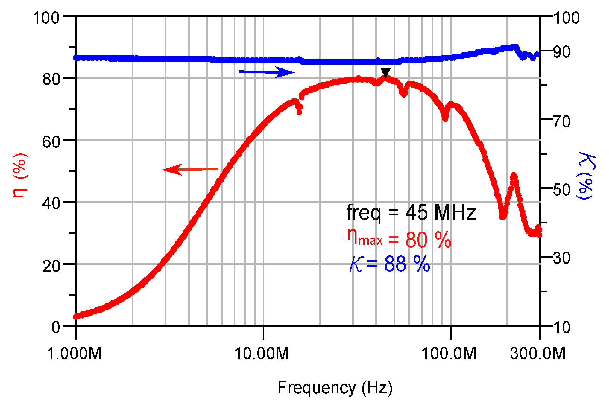
Figure 16. As expected, introducing a dielectric material into the inductive component decreased the self resonant frequency. However, the inductance was increased by a factor of 1.16 since the solenoid is surrounded by a magnetic material. The transformer’s maximum efficiency dropped down to 80% at 45 MHz due to the increase in the parasitic losses.
6. Conclusions
An approach for the fabrication of polymer based magnetic core inductive components was developed and presented. This approach utilizes the fully automated wirebonding technique to fabricate the 3-D solenoidal coils. Though the technique was used in our previously published works, the coils were wound on either air cores or laminated magnetic cores before. The open-loop inductor (Ind_20W65) made with an optimized PMC core having 65% magnetic powder reported in this work showed about twice the inductance (960 nH) of the former air core in the VHF regime while having a constant inductance up to 300 MHz, thereby, bridging the gap between the air core and magnetic core devices. Further, by fabricating and characterizing PMC core based transformers, it was verified that the PMC cores also strongly enhance the transformer efficiency and slightly the coupling factor. A transformer made out of PMC having 65% magnetic powder and solenoids with 10 turns (turns ratio 1:1) showed a maximum efficiency of 84% and a coupling factor of 96%.
The developed approach has the ability to fabricate cores with different magnetic powders and various dimensions that could eventually result in the potential to attain even better results. A process for encapsulating the device was also developed and the effect of encapsulation was studied. The complete fabrication process uses well established process like molding and wirebonding. Therefore it is cost effective and easily realizable in a laboratory environment and should be easily transferable to industrial fabrication scale. The passive components in this paper were not designed to be used in a certain converter or isolator circuit. In that case, not only the component, but the whole circuit needs to be considered to measure the load dependent efficiency as we had reported before [
16].
Acknowledgments
The authors appreciate George E. Scheller (Ceramic magnetic Inc.) for providing us the soft magnetic powders used in the PMC cores fabrication. Also, the authors would like to thank Sarai Malinal Torres Delgado (IMTEK, Laboratory of Simulations) for providing ideas to improve the PCB etching process, Jochen Hempel (IMTEK, Laboratory of Electrical Instrumentation) for providing access to probe station, Kay Steffen (IMTEK, Laboratory for Process Technology) for his help in electroplating the substrates, and Michael Pauls (IMTEK, Laboratory for Microactuators) for helping with CNC machining and in taking the SEM images.
Author Contributions
A.M. and U.W. conceived and designed the experiments; S.G.M. performed the experiments; S.G.M. and A.M. analyzed the data; S.G.M. contributed reagents/materials/analysis tools; S.G.M., A.M. and U.W. wrote the paper.
Conflicts of Interest
The authors declare no conflict of interest.
References
- Mathuna, C.O.; Wang, N.; Kulkarni, S.; Roy, S. Review of Integrated Magnetics for Power Supply on Chip (PwrSoC). IEEE Trans. Power Electron. 2012, 27, 4799–4816. [Google Scholar] [CrossRef]
- Rivas, J.M.; Leitermann, O.; Han, Y.; Perreault, D.J. A Very High Frequency DC-DC Converter Based on a Class Φ2 Resonant Inverter. IEEE Trans. Power Electron. 2011, 26, 2980–2992. [Google Scholar] [CrossRef]
- Hu, J.; Sagneri, A.; Rivas, J. High-frequency resonant SEPIC converter with wide input and output voltage ranges. IEEE Trans. Power Electron. 2012, 27, 189–200. [Google Scholar] [CrossRef]
- Andersen, T.M.; Zingerli, C.M.; Krismer, F.; Kolar, J.W.; Wang, N.; Mathuna, C. Modeling and Pareto Optimization of Microfabricated Inductors for Power Supply on Chip. IEEE Trans. Power Electron. 2013, 28, 4422–4430. [Google Scholar] [CrossRef]
- Meere, R.; Wang, N.; O’Donnell, T.; Kulkarni, S.; Roy, S.; O’Mathuna, S.C. Magnetic-Core and Air-Core Inductors on Silicon: A Performance Comparison up to 100 MHz. IEEE Trans. Magn. 2011, 47, 4429–4432. [Google Scholar] [CrossRef]
- Park, J.; Allen, M. A comparison of micromachined inductors with different magnetic core materials. In Proceedings of the 46th Electronic Components and Technology Conference, Orlando, FL, USA, 28–31 May 1996; pp. 375–381.
- Flynn, D.; Toon, A.; Allen, L.; Dhariwal, R.; Desmulliez, M.P.Y. Characterization of core materials for microscale magnetic components operating in the megahertz frequency range. IEEE Trans. Magn. 2007, 43, 3171–3180. [Google Scholar] [CrossRef]
- Wang, N.; O’Donnell, T.; Roy, S.; McCloskey, P.; O’Mathuna, C. Micro-inductors integrated on silicon for power supply on chip. J. Magn. Magn. Mater. 2007, 316, e233–e237. [Google Scholar] [CrossRef]
- Sullivan, C.R. Integrating magnetics for on-chip power: Challenges and opportunities. In Proceedings of the IEEE Custom Integrated Circuits Conference, San Jose, CA, USA, 13–16 September 2009; pp. 291–298.
- Kim, J.; Herrault, F.; Yu, X.; Kim, M.; Shafer, R.H.; Allen, M.G. Microfabrication of air core power inductors with metal-encapsulated polymer vias. J. Micromech. Microeng. 2013, 23, 035006. [Google Scholar] [CrossRef]
- Raimann, M.; Peter, A.; Mager, D.; Wallrabe, U.; Korvink, J.G. Microtransformer-Based Isolated Signal and Power Transmission. IEEE Trans. Power Electron. 2012, 27, 3996–4004. [Google Scholar] [CrossRef]
- Wang, W.; Cheng, K. A Polymer-Bonded Magnetic Core for High-Frequency Converters. IEEE Trans. Magn. 2012, 48, 4328–4331. [Google Scholar] [CrossRef]
- Kratt, K.; Badilita, V.; Burger, T.; Korvink, J.G.; Wallrabe, U. A fully MEMS-compatible process for 3D high aspect ratio micro coils obtained with an automatic wire bonder. J. Micromech. Microeng. 2010, 20, 015021. [Google Scholar] [CrossRef]
- Moazenzadeh, A.; Spengler, N.; Wallrabe, U. On-chip, MEMS-scale, high-performance, 3D solenoidal transformers. In Proceedings of the PowerMEMS 2012, Atlanta, GA, USA, 2–5 December 2012; pp. 22–25.
- Moazenzadeh, A.; Spengler, N.; Lausecker, R.; Rezvani, A.; Mayer, M.; Korvink, J.G.; Wallrabe, U. Wire bonded 3D coils render air core microtransformers competitive. J. Micromech. Microeng. 2013, 23, 114020. [Google Scholar] [CrossRef]
- Moazenzadeh, A.; Suarez Sandoval, F.; Spengler, N.; Badilita, V.; Wallrabe, U. 3-D Microtransformers for DC-DC On-Chip Power Conversion. IEEE Trans. Power Electron. 2015, 30, 5088–5102. [Google Scholar] [CrossRef]
- Jiles, D. Recent advances and future directions in magnetic materials. Acta Mater. 2003, 51, 5907–5939. [Google Scholar] [CrossRef]
- Shokrollahi, H.; Janghorban, K. Soft magnetic composite materials (SMCs). J. Mater. Process. Technol. 2007, 189, 1–12. [Google Scholar] [CrossRef]
- Raj, P.M.; Sharma, H.; Reddy, G.P.; Altunyurt, N.; Swaminathan, M.; Tummala, R.; Nair, V.; Reid, D. Novel nanomagnetic materials for high-frequency RF applications. In Proceedings of the IEEE 61st Electronic Components and Technology Conference, Lake Buena Vista, FL, USA, 31 May–3 June 2011; pp. 1244–1249.
- Shokrollahi, H.; Janghorban, K. Different annealing treatments for improvement of magnetic and electrical properties of soft magnetic composites. J. Magn. Magn. Mater. 2007, 317, 61–67. [Google Scholar] [CrossRef]
- Suryanarayana, C. Recent Development in Mechanica Alloying. Rev. Adv. Mater. Sci. 2008, 18, 203–211. [Google Scholar]
- Hasegawa, R. Design and fabrication of new soft magnetic materials. 2003, 329, 1–7. [Google Scholar] [CrossRef]
- Gibbs, M. Materials optimization for magnetic MEMS. IEEE Trans. Magn. 2007, 43, 2666–2671. [Google Scholar] [CrossRef]
- Anhalt, M.; Weidenfeller, B. Permeability of Soft Magnetic FeCoV-Composites for Varying Filler Fractions. IEEE Trans. Magn. 2010, 46, 440–442. [Google Scholar] [CrossRef]
- National Magnetics Group, Inc. CMD5005. Available online: http://www.magneticsgroup.com/pdf/CMD5005.pdf (accessed on 1 April 2016).
- Egelkraut, S. Polymer bonded soft magnetic particles for planar inductive devices. In Proceedings of the 5th International Conference on Integrated Power Systems, Nuremberg, Germany, 11–13 March 2008; pp. 1–8.
- Bang, D.; Park, J. Ni-Zn Ferrite Screen Printed Power Inductors for Compact DC-DC Power Converter Applications. IEEE Trans. Magn. 2009, 45, 2762–2765. [Google Scholar] [CrossRef]
- Wang, M.; Li, J.; Ngo, K.D.T.; Xie, H. A novel integrated power inductor in silicon substrate for ultra-compact power supplies. In Proceedings of the 25th Annual IEEE Applied Power Electronics Conference and Exposition, Palm Springs, CA, USA, 21–25 February 2010; pp. 2036–2041.
- Lu, S.; Sun, Y. 30-MHz power inductor using nano-granular magnetic material. In Proceedings of the IEEE Power Electronics Specialists Conference, Orlando, FL, USA, 17–21 June 2007; pp. 1773–1776.
- Burdeaux, D.; Townsend, P.; Carr, J.; Garrou, P. Benzocyclobutene (BCB) dielectrics for the fabrication of high density, thin film multichip modules. J. Electron. Mater. 1990, 19, 1357–1366. [Google Scholar] [CrossRef]
- Rajarathinam, V. Imprint Lithography and Characterization of Photosensitive Polymers for Advanced Microelectronics Packaging. Ph.D. Thesis, Georgia Institute of Technology, Atlanta, GA, USA, 2010. [Google Scholar]
- Chen, M.; Pham, A. Design and development of a package using LCP for RF/microwave MEMS switches. Microw. Theory 2006, 54, 4009–4015. [Google Scholar] [CrossRef]
- Sato, M.; Ishii, Y. Simple and approximate expressions of demagnetizing factors of uniformly magnetized rectangular rod and cylinder. J. Appl. Phys. 1989, 66, 983. [Google Scholar] [CrossRef]
- Sgobba, S. Physics and measurements of magnetic materials. ArXiv E-Prints 2011. [Google Scholar]
- Moazenzadeh, A.; Spengler, N.; Badilita, V.; Korvink, J.G.; Wallrabe, U. Wire bonded MEMS-scale on-chip transformers. In Proceedings of the 29th Annual IEEE Applied Power Electronics Conference and Exposition, Fort Worth, TX, USA; 2014; pp. 752–756. [Google Scholar]
- Pozar, D.M. Microwave Engineering; John Wiley & Sons Inc.: New York, NY, USA, 1998. [Google Scholar]
- Rassel, R.; Hiatt, C.; DeCramer, J.; Campbell, S. Fabrication and characterization of a solenoid-type microtransformer. IEEE Trans. Magn. 2003, 39, 553–558. [Google Scholar] [CrossRef]
- Yamaguchi, K.; Sugawara, E.; Matsuki, H.; Murakami, K. Load Characteristics of a Spiral Coil Type Thin Film Microtransformer. IEEE Trans. Magn. 1993, 29, 3207–3209. [Google Scholar] [CrossRef]
- Jin-Woo, P.; Allen, M. Ultralow-profile micromachined power inductors with highly laminated Ni/Fe cores: Application to low-megahertz DC-DC converters. IEEE Trans. Magn. 2003, 39, 3184–3186. [Google Scholar] [CrossRef]
- Meyer, C.D.; Bedair, S.S.; Morgan, B.C.; Arnold, D.P. High-inductance-density, air-core, power inductors, and transformers designed for operation at 100–500 MHz. IEEE Trans. Magn. 2010, 46, 2236–2239. [Google Scholar] [CrossRef]
- Brunet, M.; O’Donnell, T.; Baud, L.; Wang, N.; O’Brien, J.; McCloskey, P.; O’Mathuna, S. Electrical performance of microtransformers for DC-DC converter applications. IEEE Trans. Magn. 2002, 38, 3174–3176. [Google Scholar] [CrossRef]
- Xu, M.; Liakopoulos, T.M.; Ahn, C.H.; Han, S.H.; Kim, H.J.; Design, A. A Microfabricated Transformer for High-Frequency Power or Signal Conversion. IEEE Trans. Magn. 1998, 34, 1369–1371. [Google Scholar]
- Mino, M.; Yachi, T.; Tago, A.; Yanagisawa, K.; Sakakibara, K. Planar microtransfortner with monolithically-integrated rectifier diodes for micro-switching converters. IEEE Trans. Magn. 1996, 32, 291–296. [Google Scholar] [CrossRef]
- Kurata, H.; Shirakawa, K.; Nakazima, O.; Murakami, K. Solenoid-type thin-film micro-transformer. IEEE Transl. J. Magn. Japan 1994, 9, 90–94. [Google Scholar] [CrossRef]
- Tang, S.C.; Hui, S.Y.; Chung, H.S.H. A low-profile low-power converter with coreless PCB isolation transformer. IEEE Trans. Power Electron. 2001, 16, 311–316. [Google Scholar] [CrossRef]
- Moazenzadeh, A.; Spengler, N.; Wallrabe, U. High-performance, 3D-microtransformers on multilayered magnetic cores. In Proceedings of the IEEE 26th International Conference on Micro Electro Mechanical Systems, Taipei, Taiwan, 20–24 January 2013; pp. 287–290.
- Wu, R.; Liao, N.; Fang, X.; Sin, J.K.O. A Silicon-Embedded Transformer for High-Efficiency, High-Isolation, and Low-Frequency On-Chip Power Transfer. IEEE Trans. Electron Devices 2015, 62, 220–223. [Google Scholar] [CrossRef]
- Macrelli, E.; Wang, N.; Roy, S.; Hayes, M.; Paganelli, R.P.; Tartagni, M.; Romani, A. Design and Fabrication of a 315 µH Bondwire Micro-Transformer for Ultra-Low Voltage Energy Harvesting. In Proceedings of the Design, Automation and Test in Europe Conference and Exhibition (DATE), Dresden, Germany, 24–28 March 2014; pp. 1–4.
- Khan, F.; Zhu, Y.; Lu, J.; Pal, J.; Viet Dao, D. Micromachined Coreless Single-Layer Transformer Without Crossovers. IEEE Magn. Lett. 2015, 6, 1–4. [Google Scholar] [CrossRef]
Figure 1.
SEM images of NiFeZn soft magnetic powder. Due to the surface tension the particles stick to each other to form a spherical or a toroidal shape.
Figure 1.
SEM images of NiFeZn soft magnetic powder. Due to the surface tension the particles stick to each other to form a spherical or a toroidal shape.
Figure 2.
Exploded view of an encapsulated microtransformer chip.
Figure 2.
Exploded view of an encapsulated microtransformer chip.
Figure 3.
Schematic of the Au electroplated substrate.
Figure 3.
Schematic of the Au electroplated substrate.
Figure 4.
Schematic of the substrate during each fabrication process steps. (a) Substrate with contact pads after CNC milling; (b) An exploded view of the clamping assembly.
Figure 4.
Schematic of the substrate during each fabrication process steps. (a) Substrate with contact pads after CNC milling; (b) An exploded view of the clamping assembly.
Figure 5.
Schematic of the demolding method utilizing the PMMA press to distribute the force along the substrate.
Figure 5.
Schematic of the demolding method utilizing the PMMA press to distribute the force along the substrate.
Figure 6.
Microscopic images of the magnetic core transformer.Microscopic image of the magnetic core transformer.
Figure 6.
Microscopic images of the magnetic core transformer.Microscopic image of the magnetic core transformer.
Figure 7.
An exploded view of the encapsulation process.
Figure 7.
An exploded view of the encapsulation process.
Figure 8.
Fully processed substrate with 14 pure epoxy encapsulated transformer chips (white) and 13 magnetic epoxy encapsulated transformer chips (grey).
Figure 8.
Fully processed substrate with 14 pure epoxy encapsulated transformer chips (white) and 13 magnetic epoxy encapsulated transformer chips (grey).
Figure 9.
Mechanical stability of the AW4510 based PMC sample posts fabricated on an FR4 substrate. The error bars denote the standard deviation of 5 posts.
Figure 9.
Mechanical stability of the AW4510 based PMC sample posts fabricated on an FR4 substrate. The error bars denote the standard deviation of 5 posts.
Figure 10.
Impedance of the inductors with 10 turns having cores with different percentage of the magnetic powder. Z_10 pure is the inductor with a core made out of the pure epoxy, Z_ 10WY is the impedance of inductors having a core made out of Y% of the magnetic powder mixed with the epoxy.
Figure 10.
Impedance of the inductors with 10 turns having cores with different percentage of the magnetic powder. Z_10 pure is the inductor with a core made out of the pure epoxy, Z_ 10WY is the impedance of inductors having a core made out of Y% of the magnetic powder mixed with the epoxy.
Figure 11.
Inductance of the inductors with 10 turns having cores with different percentage of the magnetic powder Ind_10 pure is represents the inductors with pure epoxy core, Ind_XWY stands for inductors having a solenoid made of X turns and core made out of Y% magnetic powder mixed with the epoxy.
Figure 12.
Quality factor of the inductors with 10 turns having cores with different percentage of the magnetic powder. The peak values of each sample and the corresponding frequency are placed in the boxes.
Figure 12.
Quality factor of the inductors with 10 turns having cores with different percentage of the magnetic powder. The peak values of each sample and the corresponding frequency are placed in the boxes.
Figure 13.
Maximum inductance and quality factor as a function of the number of turns for varying percentage of magnetic powder. The dotted lines indicate the and the solid line the .
Figure 13.
Maximum inductance and quality factor as a function of the number of turns for varying percentage of magnetic powder. The dotted lines indicate the and the solid line the .
Figure 14.
Frequency dependent values of the PMC core inductors for varying number of turns. The composite was made out of 65% powder. (a) Inductance; (b) Quality factor.
Figure 14.
Frequency dependent values of the PMC core inductors for varying number of turns. The composite was made out of 65% powder. (a) Inductance; (b) Quality factor.
Figure 15.
Efficiency and coupling factor of the transformer with PMC core. The sample was made with 10 turns and a turn ratio of 1:1. The composite was made out of 65% powder.
Figure 15.
Efficiency and coupling factor of the transformer with PMC core. The sample was made with 10 turns and a turn ratio of 1:1. The composite was made out of 65% powder.
Figure 16.
Efficiency and coupling factor of the encapsulated transformer with PMC core. The sample was made with 10 turns and a turn ratio of 1:1 . The core composite was made out of 65% powder. The encapsulation composite was made of 20% powder.
Figure 16.
Efficiency and coupling factor of the encapsulated transformer with PMC core. The sample was made with 10 turns and a turn ratio of 1:1 . The core composite was made out of 65% powder. The encapsulation composite was made of 20% powder.
Table 1.
Properties of the NiFeZn Soft Magnetic Powder * [
25].
Table 1.
Properties of the NiFeZn Soft Magnetic Powder * [25].
| Property | Units | Symbol | Standard Test Condition | Value |
|---|
| Initial Permeability | - | | f = 10 kHz; B T | % |
| Saturation Flux Density | T | | H = 795.7 A/m | 0.32 |
| Remanence | T | | - | 0.15 |
| Coercive Force | A/m | | - | 15.9 |
| Loss Factor | | tan δ/ | f = 1 MHz; B = 0.1 T | ≤250 |
| Temperature Coefficient of | %/C | - | - | ≤0.7 |
| Volume Resistivity | cm | ρ | - | |
| Curie Temperature | C | | - | ≥130 |
Table 2.
Binder polymers for fabricating PMC cores to be used in high frequency applications.
Table 2.
Binder polymers for fabricating PMC cores to be used in high frequency applications.
| Polymers | Dielectric Constant | Young’s Modulus | Water Absorption | CTE | |
|---|
| (GPa) | (ISO 62-80) (%) | (PPM/C) | (C) |
|---|
| BCB | 2.7 | 2.9 | 0.24 | 52 | >350 |
| Avatrel | 2.5 | 0.5–1.56 | 0.06 | 83 | 250 |
| LCP | 3 | 40 | 0.1 | 16 | 150 |
| KAPTON * | 3.5 | 2.5 | 2.5 | 20 | 360–410 |
| Su8 | 3 | 4.02 | 0.55 | 52 | 210 |
| PDMS | 2.8 | 0.4–0.9 | >1 | 310 | - |
| Epoxy (Araldite) | 3 | >5 | <0.8 | <15 | 50–100 |
Table 3.
Process conditions for obtaining the AW4510 + HW4804 based epoxy composite core with 1 mm in diameter and 2 mm height. The pre-heating was done before dispensing the composite to enhance the viscocity of the mixture. The post curing was done at 100 C in an oven for 1 h.
Table 3.
Process conditions for obtaining the AW4510 + HW4804 based epoxy composite core with 1 mm in diameter and 2 mm height. The pre-heating was done before dispensing the composite to enhance the viscocity of the mixture. The post curing was done at 100 C in an oven for 1 h.
| Percentage of Magnetic Powder | Pre- Heating Time (50 C) | Waiting Time before Dispensing |
|---|
| (%) | (min) | (min) |
|---|
| Pure | 15 | 45 |
| 45 | 10 | 15 |
| 55 | 10 | 10 |
| 65 | 5 | 10 |
Table 4.
Comparison between the inductance achieved in this work and the previous work.
Table 4.
Comparison between the inductance achieved in this work and the previous work.
| N_Core Used | L @ 1 MHz | @ MHz | SRF |
|---|
| (nH) | (MHz) |
|---|
| 20_Air Core [encapsulated] [15] | 464 | 22 @ 78 | 218 |
| 18_Metglas Core [Open-loop] [35] | 1024 | 9 @ 37 | 130 |
| 40_Metglas Core [Closed-loop] * [16] | | 7 @ 0.3 | 27 |
| Ind_30_W45 | 1300 | 19 @ 43 | 300 |
| Ind_30_W55 | 1700 | 14 @ 30 | 204 |
| Ind_30_W65 | 2090 | 13 @ 14 | 200 |
| Ind_20_W65 | 961 | 12 @ 17 | 300 |
Table 5.
Survey on the state of the art microtransformers (pure RF microinductors are excluded). All the devices except the ones which marked with (*) were characterized using 50 Ω load.
Table 5.
Survey on the state of the art microtransformers (pure RF microinductors are excluded). All the devices except the ones which marked with (*) were characterized using 50 Ω load.
| Refferences | Citation | L/ | | | κ | Core Volume | Layout | Core Material |
|---|
| (nH/Ω) | (%) | (MHz) | (%) | (mm) |
|---|
| Rassel et al., 2003 | [37] | 100 | 10 | 0.5 | 90 | 0.025 | Solenoid | NiFe |
| Yamaguchi et al., 1993 | [38] | 357 | 29 | 20 | 90 | 3.77 | Planar | CoFeSiB |
| Allen et al., 2003 | [39] | 371 | 32 | 26 | 85 | 3.99 | Planar | NiFe |
| Meyer et al., 2010 | [40] | 52.6 | 40 | 50 | 63 | - | Stack planar | Air |
| Brunet et al., 2002 | [41] | 900 | 40 | 2 | - | 1.45 | Planar | NiFe |
| Xu et al., 1998 | [42] | 720 | 45 | 10 | 90 | 0.520 | Solenoid | NiFe |
| Sakakibara et al., 1996 | [43] | 106 | 50 | 10 | 93 | 10 | Planar | CoZrRe |
| Kurata et al., 1994 | [44] | 24 | 50 | 100 | 92 | 0.042 | Solenoid | CoFeSiB |
| Tang et al., 2001 | [45] | 154 | 63 | 8 | 95 | - | Planar | Air |
| Wang et al., 2007 | [8] | 840 | 63 | 10 | 93 | 0.355 | Planar | NiFe |
| Raimann et al., 2012 | [11] | 142.3 | 65 | 45 | 86 | 1.6 | Solenoid | Ferrite |
| Moazenzadeh et al., 2013 | [15] | 175.6 | 68 | 54 | 94 | 0.674 | Solenoid | Air |
| Moazenzadeh et al., 2014 | [16] | 5714 | 71 | 1.11 | 98 | 7.5 | Solenoid | CoFeNiSiB |
| Moazenzadeh et al., 2013 | [46] | 395 | 74 | 32 | 98 | 0.720 | Solenoid | CoFeNiSiB |
| Wu et al., 2015 | [47] | 195.5 | - | - | 98 | 0.2 | Planar | Air |
| Macrelli et al., 2014 | [48] | 73256 | - | - | 90 | 4.32 | Toroid | MnZn |
| Khan et al., 2015 | [49] | 16.2 | ∼55 | - | 75 | 0.044 | Fractal shaped | Air |
| Tra_10_W65 * | This work | 158 | 84 | 61 | 96 | 1.6 | Solenoid | NiFeZn+epoxy |
© 2016 by the authors. Licensee MDPI, Basel, Switzerland. This article is an open access article distributed under the terms and conditions of the Creative Commons Attribution (CC-BY) license ( http://creativecommons.org/licenses/by/4.0/).


