
A New Method for a Piezoelectric Energy Harvesting System Using a Backtracking Search Algorithm-Based PI Voltage Controller

Abstract
:
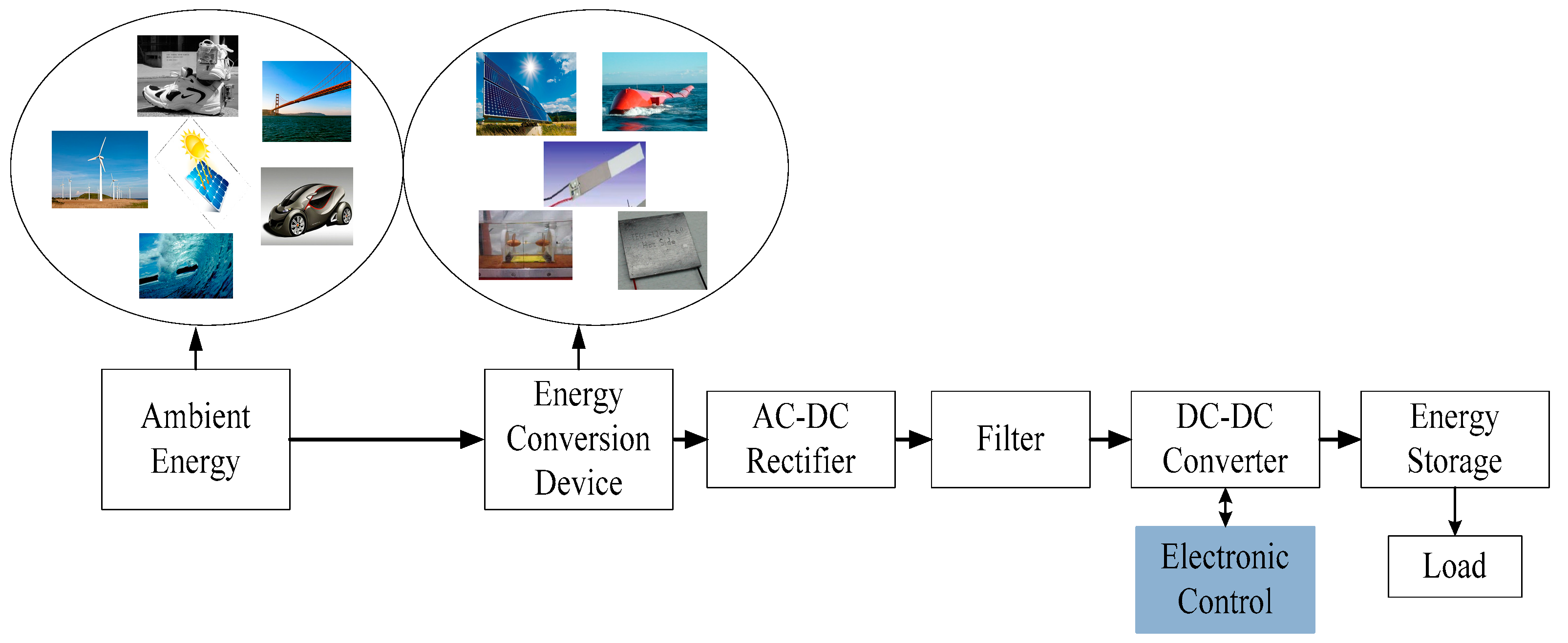
1. Introduction
2. Design PI Voltage Controller Based on BSA for PEHS
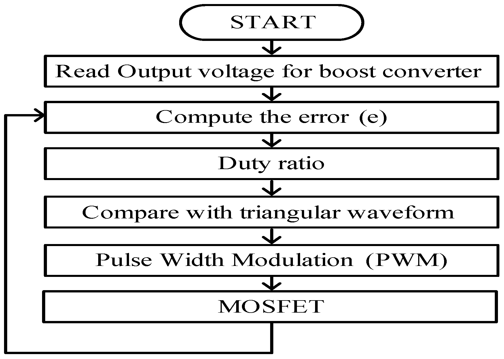
2.1. Conventional PI Voltage Controller
2.2. Conventional Backtracking Search Algorithm (BSA)
2.3. Control Strategy
3. Proposed BSA-PI Voltage Controller for Vibration-Based PEHS
3.1. Backtracking Search Algorithm (BSA)
3.2. Optimal PI Voltage Controllers
3.3. Input Information
3.4. Objective Function
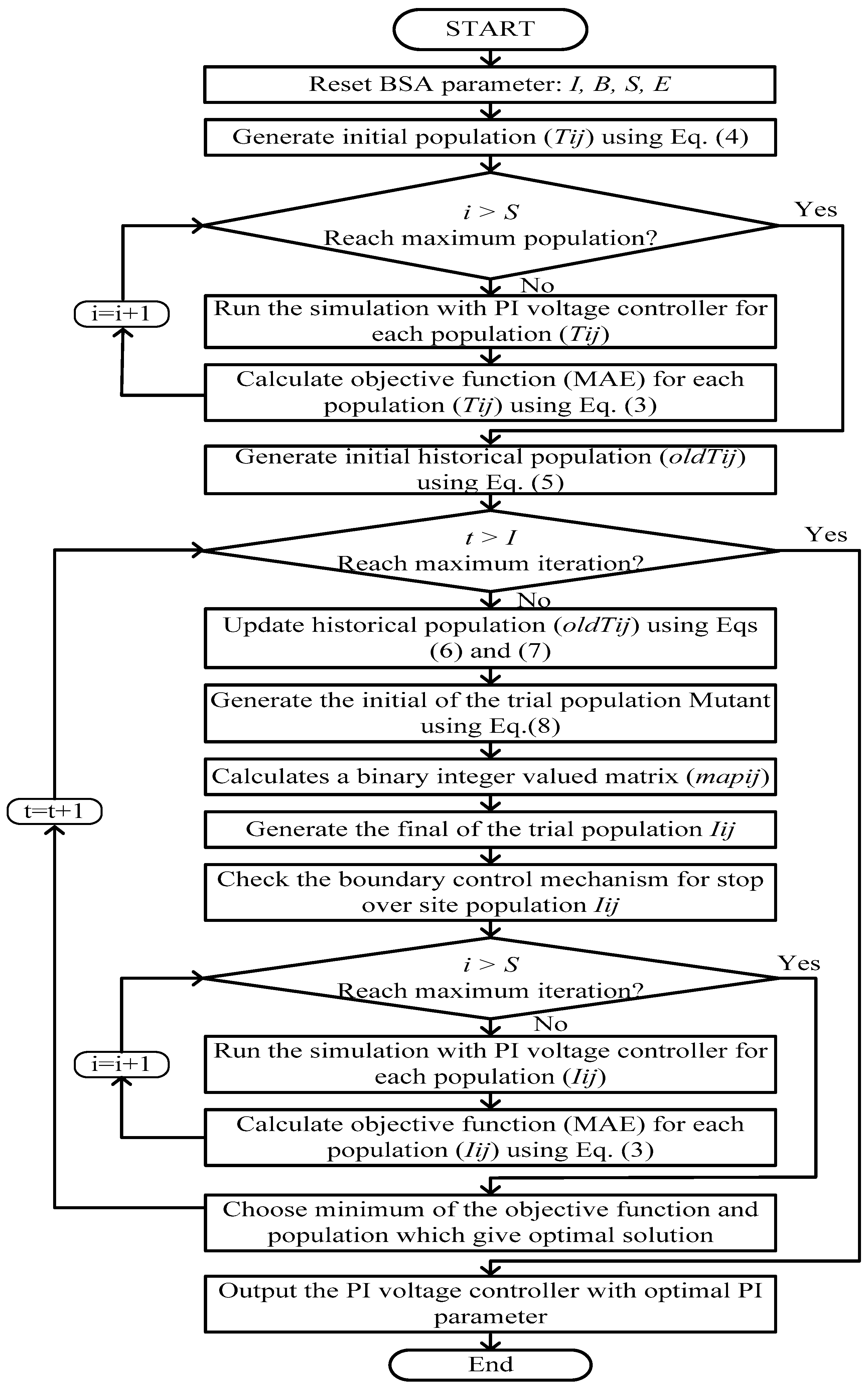
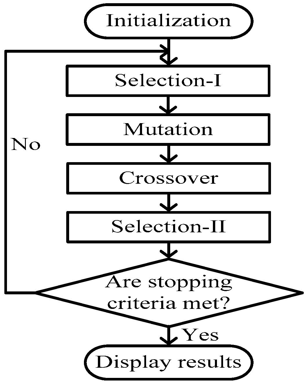
3.5. BSA for an Optimal PI Voltage Controller
3.5.1. Initialization
3.5.2. Selection-I
3.5.3. Mutation
3.5.4. Crossover
3.5.5. Selection-II
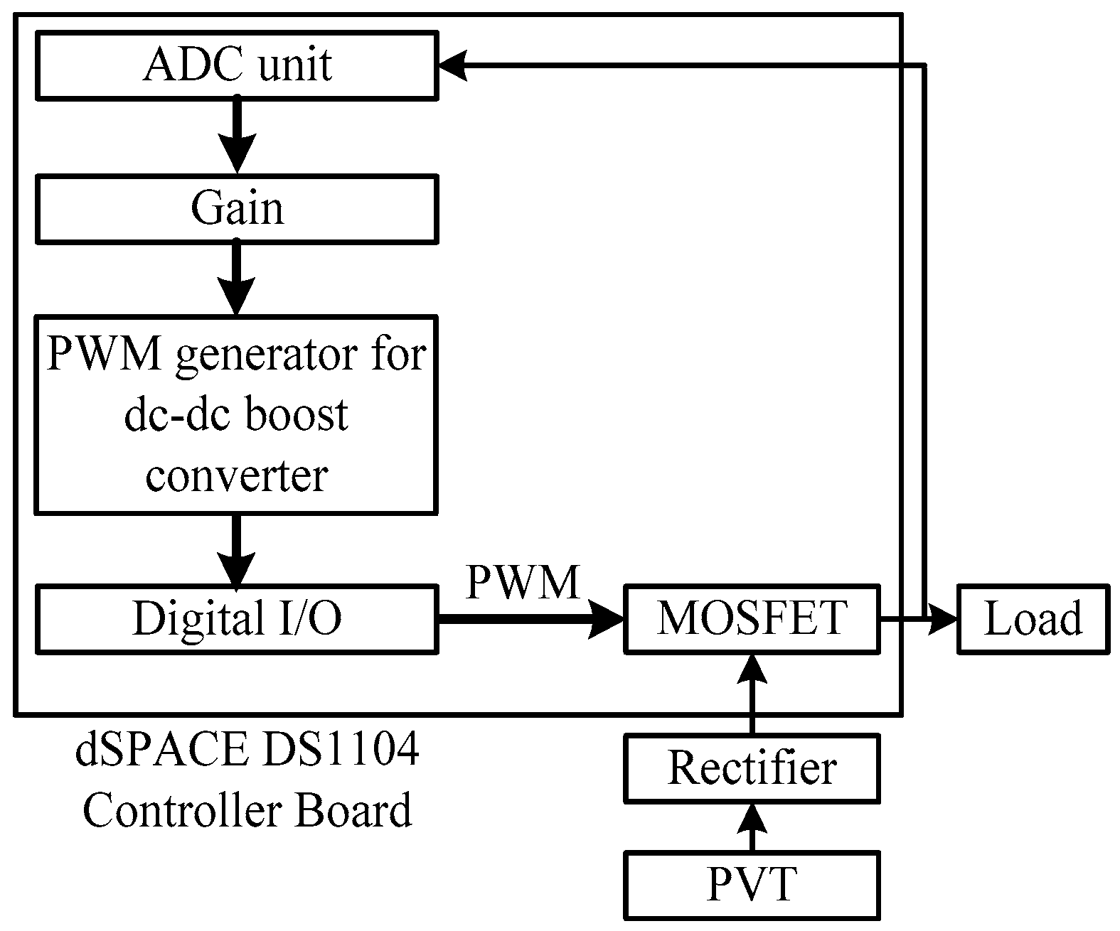
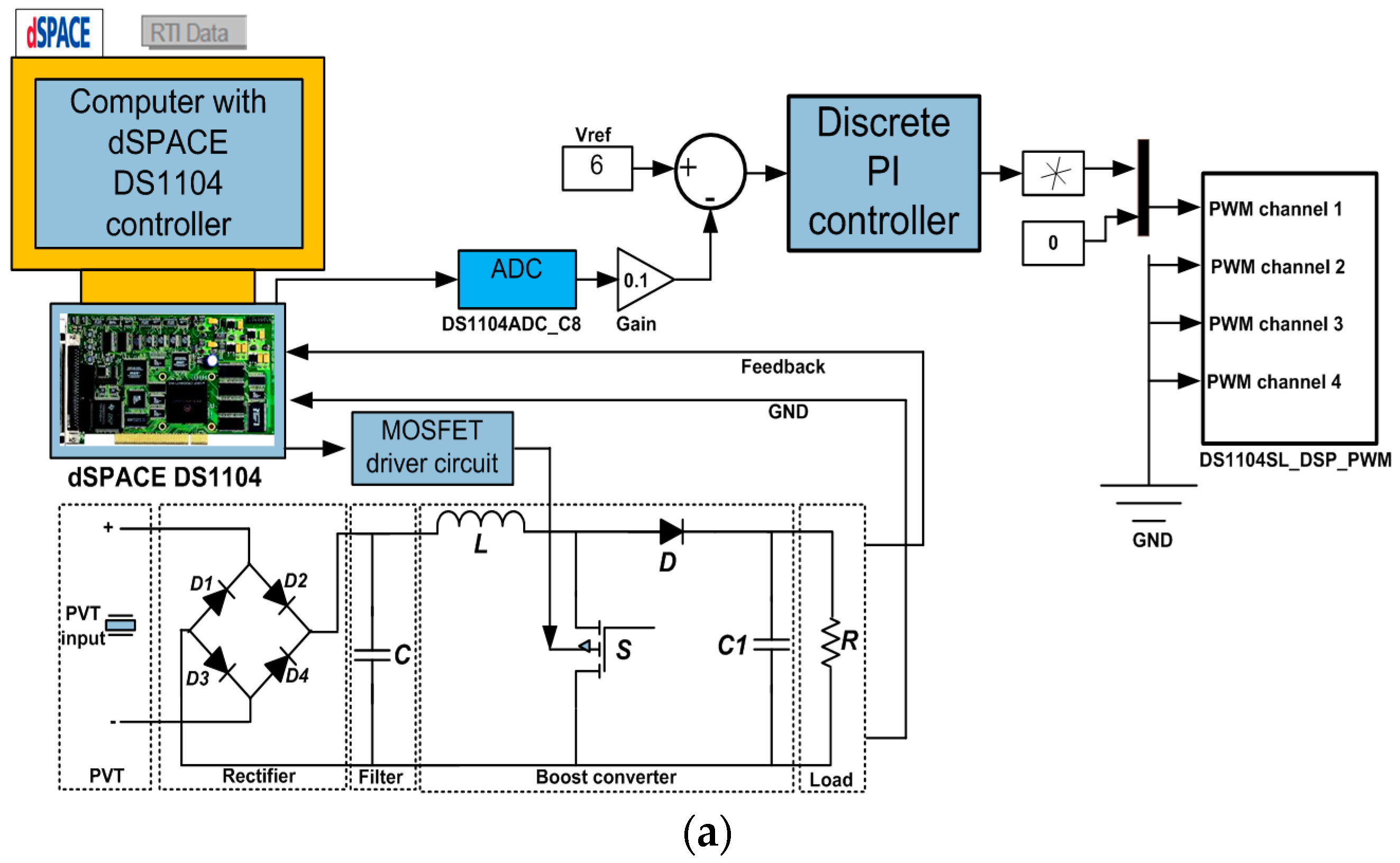
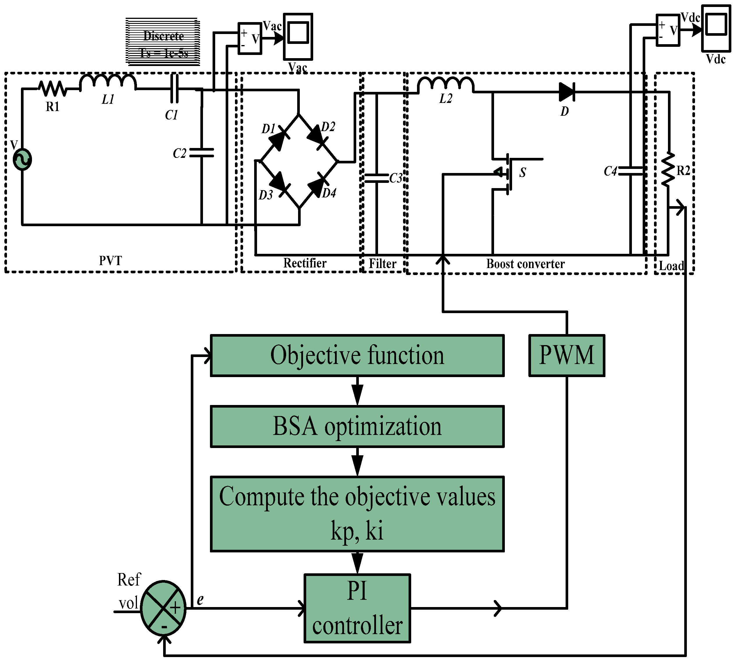
4. Simulation Model PI Voltage Controller for PEHS Utilizing the Proposed BSA Technique
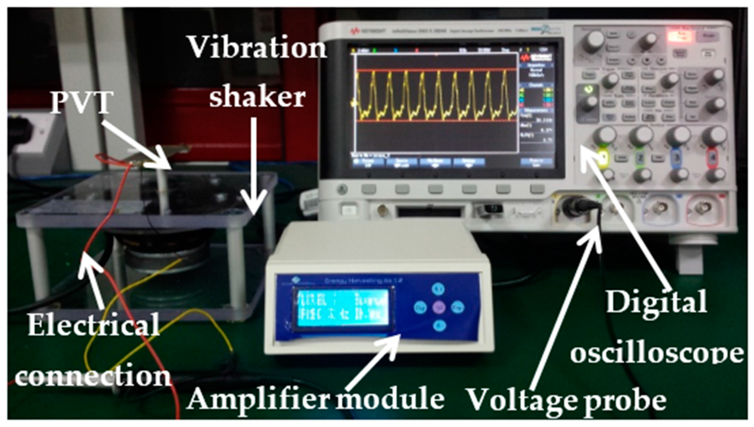
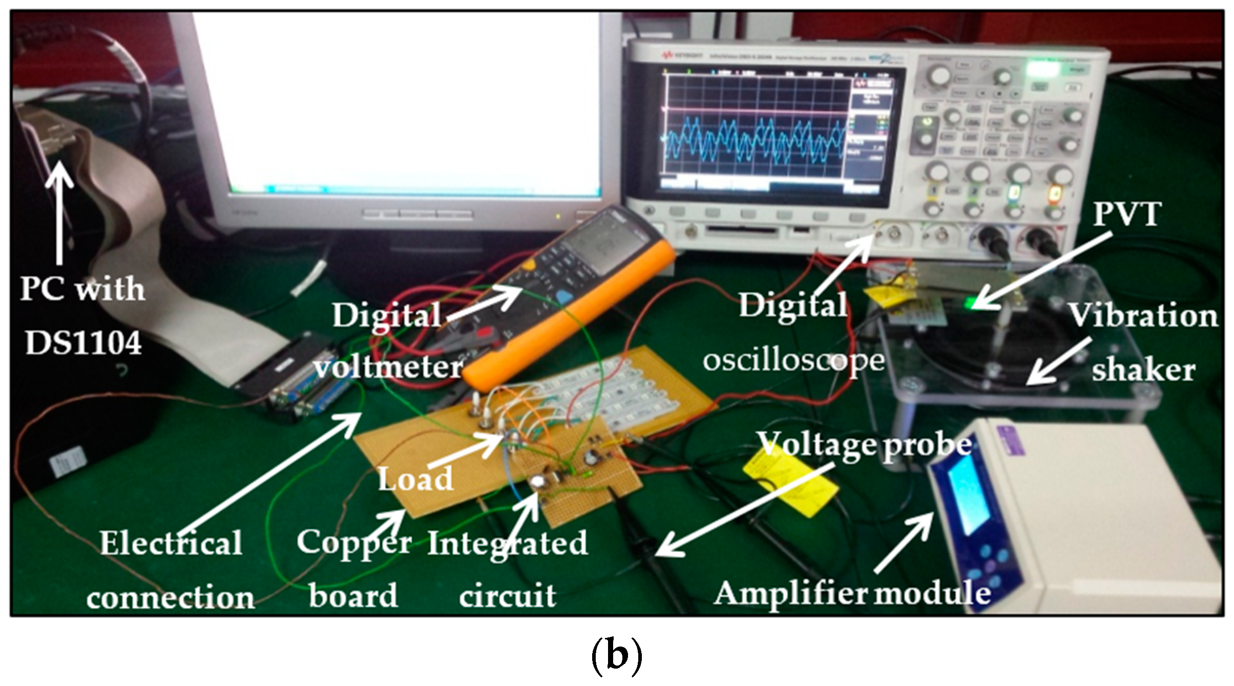
5. Experimental Setup
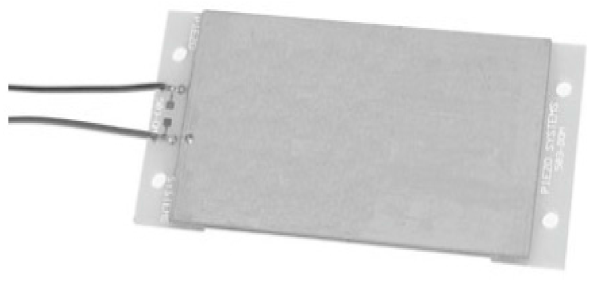
5.1. Piezoelectric Vibration Transducer
5.2. Experimental Setup of the PEHS
6. Results and Discussion
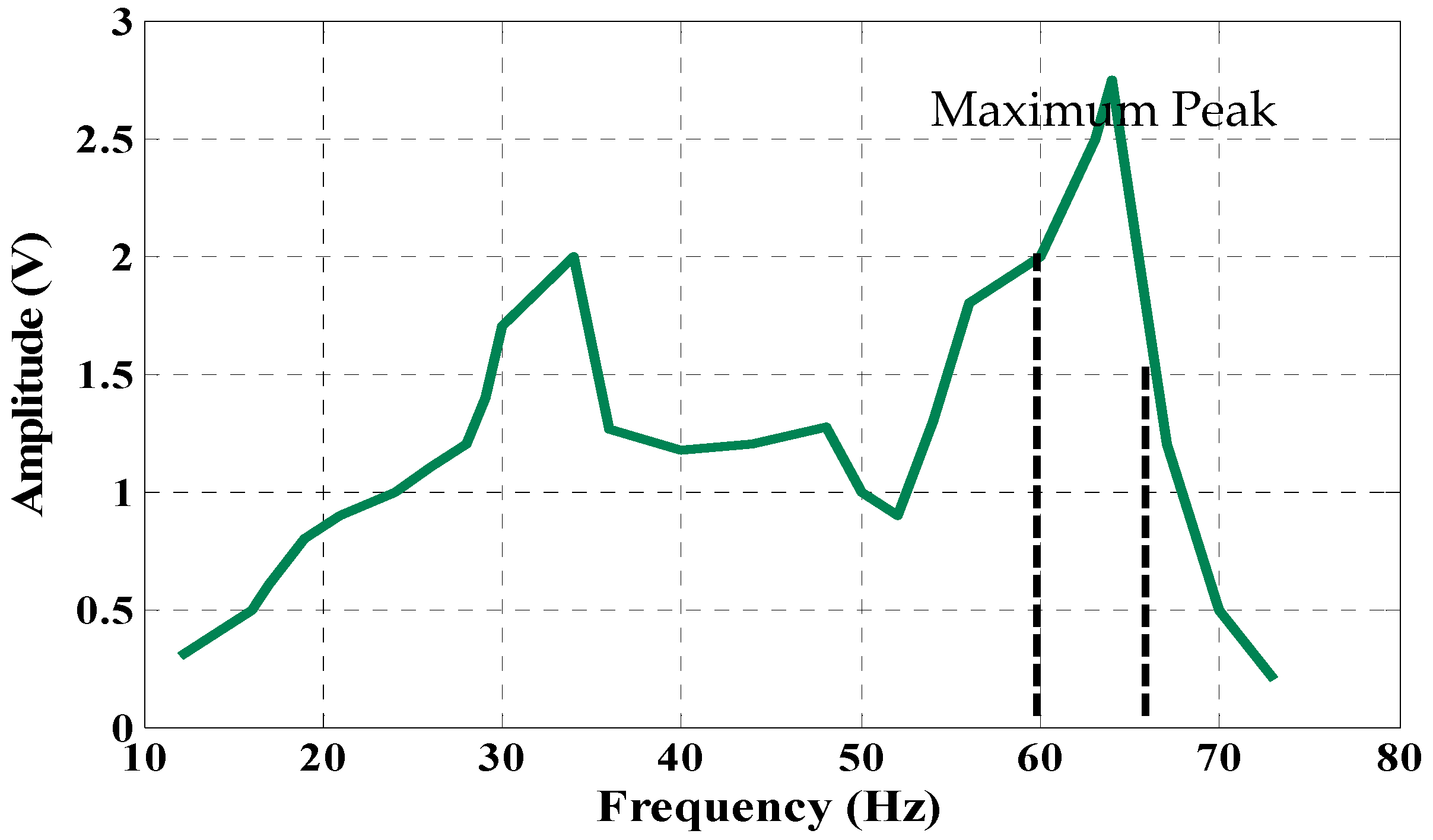
6.1. Extracting Data from the PVT
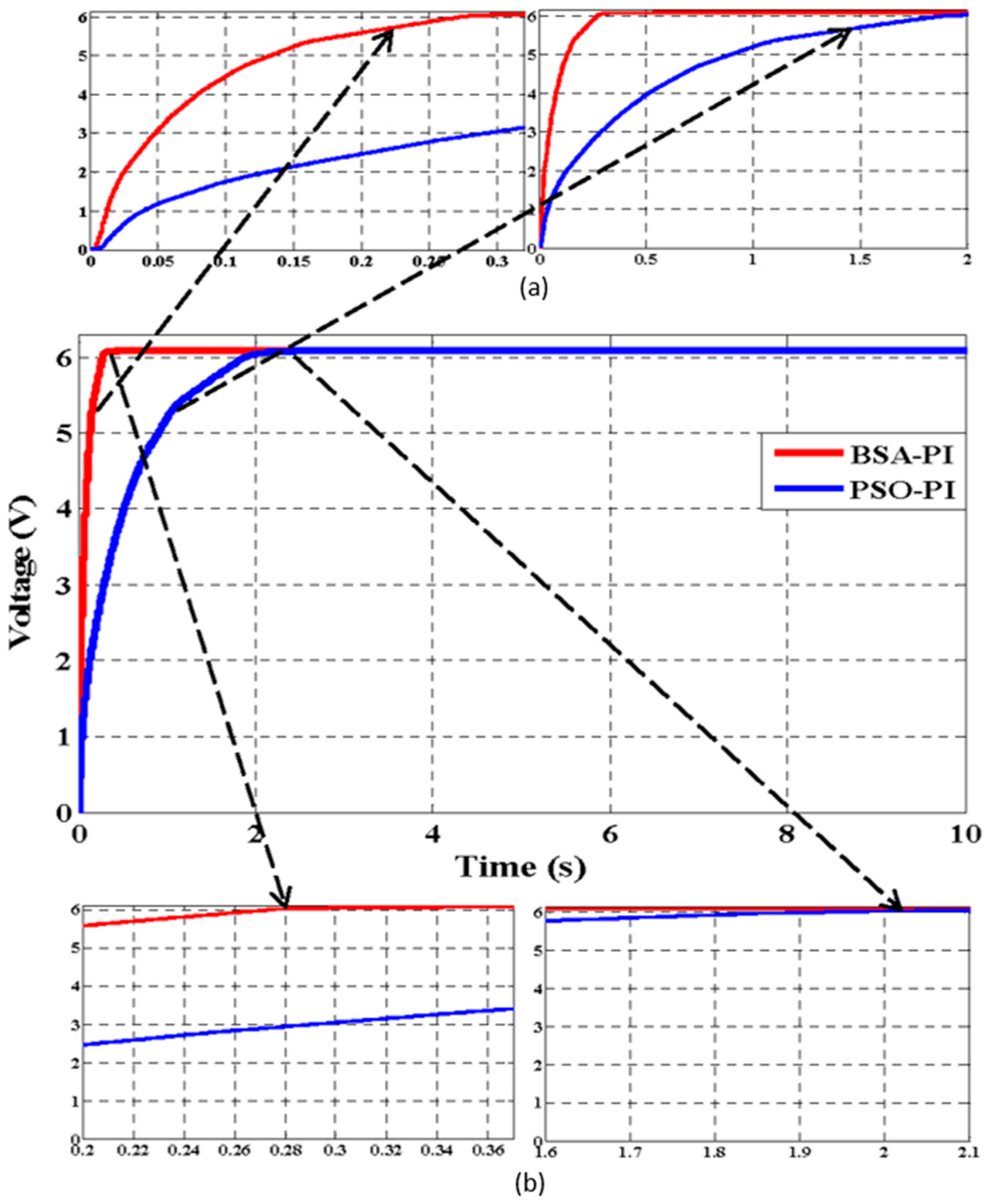
6.2. Simulation and Analysis
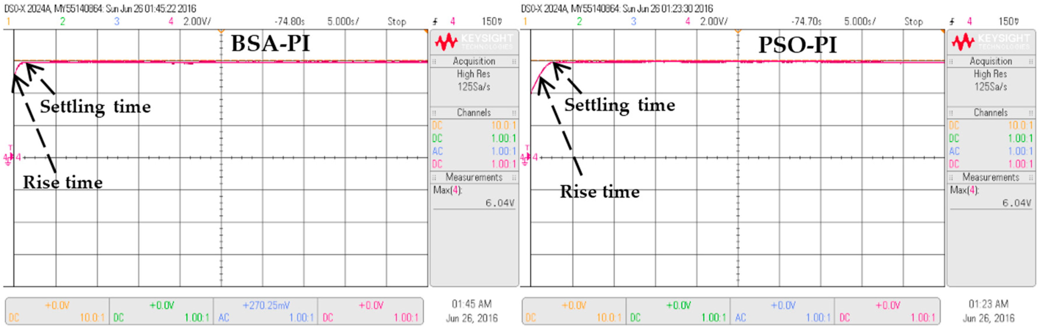
6.3. Simulation and Experimental Results in Terms of Rise and Settling Time for the PEHS
6.4. Simulation and Experimental Results of a Fully-Integrated PEHS
7. Conclusions
Acknowledgments
Author Contributions
Conflicts of Interest
References
- Peng, S.W.; Shih, P.J.; Dai, C.L. Manufacturing and characterization of a thermoelectric energy harvester sing the CMOS-MEMS technology. Micromachines 2015, 6, 1560–1568. [Google Scholar] [CrossRef]
- Wang, Y.J.; Chen, C.D.; Lin, C.C.; Yu, J.H. A nonlinear suspended energy harvester for a tire pressure monitoring system. Micromachines 2015, 6, 312–327. [Google Scholar] [CrossRef]
- Liu, H.; Chen, T.; Sun, L.; Lee, C. An electromagnetic MEMS energy harvester array with multiple vibration modes. Micromachines 2015, 6, 984–992. [Google Scholar] [CrossRef]
- Hassanalieragh, M.; Soyata, T.; Nadeau, A.; Sharma, G. UR-SolarCap: An open source intelligent auto-wakeup solar energy harvesting system for supercapacitor-based energy buffering. IEEE Access 2016, 4, 542–557. [Google Scholar] [CrossRef]
- Yang, Z.; Jean, Z. Toward harvesting vibration energy from multiple directions by a nonlinear compressive-mode piezoelectric transducer. IEEE Trans. Mechatron. 2016, 21, 1787–1791. [Google Scholar] [CrossRef]
- Mohamed, R.; Sarker, M.R.; Mohamed, A. An optimization of rectangular shape piezoelectric energy harvesting cantilever beam for micro devices. Int. J. Appl. Electromagn. Mech. 2016, 50, 537–548. [Google Scholar] [CrossRef]
- Rezaeisaray, M.; Gowini, M.; Sameoto, D. Low frequency piezoelectric energy harvesting at multi vibration mode shapes. Sens. Actuators A Phys. 2015, 228, 104–111. [Google Scholar] [CrossRef]
- Cui, X.; Teng, M.; Hu, J. PSPICE-Based Analyses of the Vibration Energy Harvester System with Multiple Piezoelectric Units. Can. J. Electr. Comput. Eng. 2015, 38, 246–250. [Google Scholar] [CrossRef]
- Ayaz, M.; Farjah, E.; Ghanbari, T. A Novel Self-Starting Ultra Low-Power and Low-Voltage Two-Stage DC-DC Boost Converter for Microbial Energy Harvesting. In Proceedings of the IEEE 4th International Conference on Consumer Electronics, Berlin, Germany, 7–10 September 2014; pp. 498–502.
- Mahidur, R.S.; Ramizi, M.A. Batteryless low input voltage micro-scale thermoelectric based energy harvesting interface circuit with 100mv start-up voltage. Przeglad Elektrotechniczny 2014, 90, 49–52. [Google Scholar]
- Ramadass, Y.; Chandrakasan, A. Minimum energy tracking loop with embedded DC/DC converter enabling ultra-low-voltage operation down to 250 mV in 65 nm CMOS. IEEE J. Solid-State Circuits 2008, 43, 256–265. [Google Scholar] [CrossRef]
- Ottman, G.K.; Hofmann, H.F.; Bhatt, A.C.; Lesieutre, G.A. Adaptive piezoelectric energy harvesting circuit for wireless remote power supply. IEEE Trans. Power Electron. 2002, 17, 669–676. [Google Scholar] [CrossRef]
- Ottman, G.K.; Hofmann, H.F.; Lesieutre, G.A. Optimized piezoelectric energy harvesting circuit using step-down converter in discontinuous conduction mode. IEEE Trans. Power Electron. 2003, 18, 696–703. [Google Scholar] [CrossRef]
- Antonio, J.B.; Barbi, I. Input-series and output-series connected modular output capacitor full-bridge PWM DC-DC converter. IEEE Trans. Ind. Electron. 2015, 62, 6213–6221. [Google Scholar]
- Antonio, J.B.; Barbi, I. Input-Series and Output-Series Connected Modular Full-Bridge PWM DC-DC Converter with Capacitive Output Filter and Common Duty Cycle. In Proceedings of the 11th IEEE/IAS International Conference on Industry Applications (INDUSCON), Juiz de Fora, Brazil, 7–10 December 2014; pp. 1–8.
- Aldo, B.; Corsanini, D.; Landi, A.; Sani, L. Circle based Criteria for performance evaluation of controlled DC/DC switching Converters. IEEE Trans. Ind. Electron. 2006, 53, 1862–1869. [Google Scholar]
- Basilio, J.C.; Matos, S.R. Design of PI and PID controllers with transient performance specification. IEEE Trans. Educ. 2002, 45, 364–370. [Google Scholar] [CrossRef]
- LE, T.; Sentieys, O.; Berder, O.; Pegatoquet, A. Power Manager with PID Controller in Energy Harvesting Wireless Sensor Networks. In Proceedings of the IEEE International Conference on Green Computing and Communications, Besançon, France, 20–23 November 2012; pp. 668–670.
- Amala, J.; Rajan, S.; Vengatesh, R. Design and analysis of high frequency Soft-Switching Boost Converter employing Electronic PI-Controller. In Proceedings of the International Conference on Emerging Trends in Electrical and Computer Technology (ICETECT), Nagercoil, India, 23–24 March 2011; pp. 392–397.
- Hazzab, A.; Bousserhane, I.K.; Zerbo, M.; Sicard, P.; Murphy, G.V. Real time implementation of fuzzy gain scheduling of PI controller for induction motor machine control. Neural Process. Lett. 2006, 24, 203–215. [Google Scholar] [CrossRef]
- Ngo, P.D.; Shin, Y.C. Gain estimation of nonlinear dynamic systems modeled by an FBFN and the maximum output scaling factor of a self-tuning PI fuzzy controller. Eng. Appl. Artif. Intell. 2015, 42, 1–15. [Google Scholar] [CrossRef]
- Perry, A.G.; Feng, G.; Liu, Y.F. A design method for PI-like fuzzy logic controller for DC-DC converter. IEEE Trans. Ind. Electron. 2007, 54, 2688–2695. [Google Scholar] [CrossRef]
- Elmas, C.; Yigit, T. Genetic algorithm based on-line tuning of a PI controller for a switched reluctance motor drive. Electr. Power Compon. Syst. 2007, 35, 675–691. [Google Scholar] [CrossRef]
- Mo, H.; Yin, Y. Research on PID Tuning of Servo-System Based on Bacterial Foraging Algorithm. In Proceedings of the 7th International Conference on Natural Computation (ICNC), Shanghai, China, 26–28 July 2011; Volume 3, pp. 1758–1762.
- Afrozi, M.N.; Aghdam, M.H.; Naebi, A.; Aghdam, S.H. Simulation and Optimization of Asynchronous AC Motor Control by Partial Swarm Optimization (PSO) and Emperor Algorithm. In Proceedings of the 5th UKSim European Symposium on Computer Modeling and Simulation (EMS), Madrid, Spain, 16–18 November 2011; pp. 251–256.
- Jamal, A.; Hannan, M.A.; Mohamed, A.; Abdolrasol, M. Fuzzy logic speed controller optimization approach for induction motor drive using backtracking search algorithm. Measurement 2016, 78, 49–62. [Google Scholar]
- Civicioglu, P. Backtracking search optimization algorithm for numerical optimization problems. Appl. Math. Comput. 2013, 219, 8121–8144. [Google Scholar] [CrossRef]
- Astrom, K.J.; Hagglund, T. Automatic Tuning of PID Controllers; International Society of Automation (ISA): Durham, NC, USA, 1988. [Google Scholar]
- Youssef, O.; Kamal, A.H.; Luc, A.G. Packed U cells multilevel converter topology: Theoretical study and experimental validation. IEEE Trans. Ind. Electron. 2011, 58, 1294–1306. [Google Scholar]
- dSPACE DS1104. Hardware Installation and Configuration and ControlDesk Experiment Guide; dSPACE GmbH: Paderborn, Germany, 2008. [Google Scholar]
- Zainal, S.; Toh, L.S.; Mohd, Z.R. Hardware Implementation of the High Frequency Link Inverter Using dSPACE DS1104 Digital Signal Processing Board. In Proceedings of the IEEE International Power and Energy Conference (PECon’06), Malacca, Malaysia, 28–29 November 2006; pp. 348–352.
- Lin, Q.; Gao, L.; Li, X.; Zhang, C. A hybrid backtracking search algorithm for permutation flow-shop scheduling problem. Comput. Ind. Eng. 2015, 85, 437–446. [Google Scholar] [CrossRef]
- Song, X.; Zhang, X.; Zhao, S.; Li, L. Backtracking search algorithm for effective and efficient surface wave analysis. Comput. Ind. Eng. 2015, 114, 19–31. [Google Scholar] [CrossRef]
- Askarzadeh, A.; Coelho, L.S. A backtracking search algorithm combined with Burger’s chaotic map for parameter estimation of PEMFC electrochemical model. Int. J. Hydrog. Energy 2014, 39, 11165–11174. [Google Scholar] [CrossRef]
- El-Fergany, A.; Coelho, L.S. Optimal allocation of multi-type distributed generators using backtracking search optimization algorithm. Int. J. Electr. Power Energy Syst. 2015, 64, 1197–1205. [Google Scholar] [CrossRef]
- Wang, H.; Tang, Y.; Khaligh, A. A Bridgeless Boost rectifier for low-voltage energy harvesting applications. IEEE Trans. Power Electron. 2013, 28, 5206–5214. [Google Scholar] [CrossRef]
- Richelli, A.; Comensoli, S.; Kovacs-Vajna, Z.M. A DC/DC boosting technique and power management for ultralow-voltage energy harvesting applications. IEEE Trans. Ind. Electron. 2012, 59, 2701–2708. [Google Scholar] [CrossRef]
- Bertacchini, A.; Scorcioni, S.; Cori, M.; Larcher, L.; Pavan, P. 250 mv Input Boost Converter for Low Power Applications. In Proceedings of the IEEE International Symposium on Industrial Electronics (ISIE), Bari, Italy, 4–7 July 2010; pp. 533–538.


| Parameter | PVT | Units |
|---|---|---|
| Piezo Material | 5A4 | E |
| Weight | 10.4 | grams |
| Stiffness | 1.9 × 10² | N/m |
| Capacitance | 232 | nF |
| Rated Tip Deflection | ±2.6 | (mmpeak) |
| Maximum Rated Frequency | 52 | Hz |
| Equipment Name | Equipment Model | Equipment Quantity |
|---|---|---|
| PVT | EH220-A4-503YB | 1 |
| Amplifier Module | Smart material | 1 |
| Vibration Shaker | - | 1 |
| Digital Voltmeter | 72-7130A | 1 |
| Copper-Board | - | 2 |
| Digital Oscilloscope | DSO × 2074A | 1 |
| dSPACE Controller | DS1104 | 1 |
| Voltage Probe | - | 2 |
| Switch | - | 5 |
| Resistive load LED | - | 5 |
| Inductor L | 3500 μH | 1 |
| Filter Capacitor C | 300 μF | 2 |
| MOSFETs | SI9926CDY | 1 |
| Schottky Diodes | IN5819 | 5 |
| Frequency (Hz) | 12 | 16 | 19 | 21 | 24 | 28 | 30 | 34 | 36 | 40 | 44 | 48 | 50 | 54 | 60 | 65 | 70 | 74 |
| Vrms | 0.3 | 0.5 | 0.8 | 0.9 | 1 | 1.2 | 1.7 | 2 | 1.26 | 1.17 | 1.2 | 1.27 | 1 | 1.3 | 2 | 2.75 | 0.5 | 0.2 |
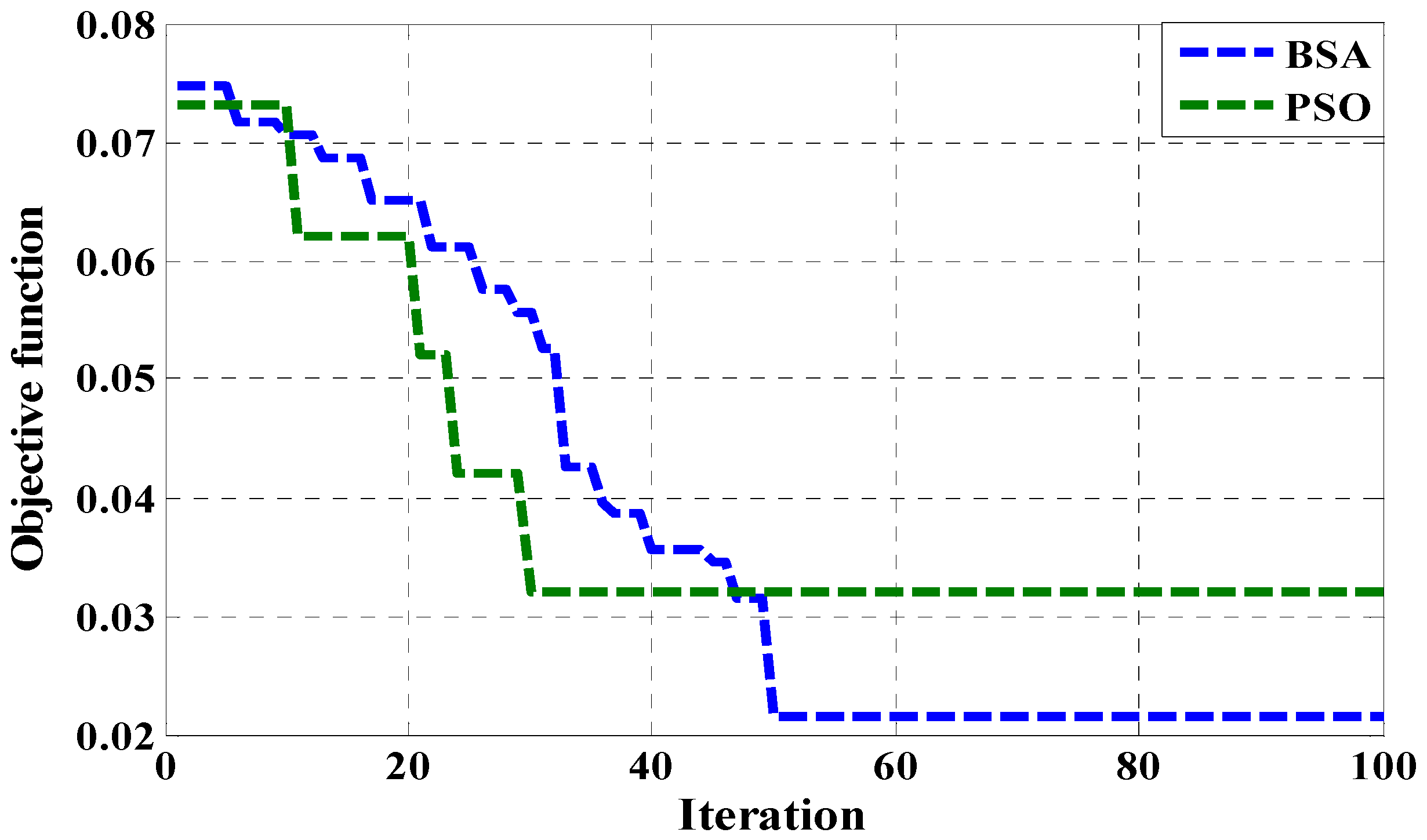
| MAE | Trial-and-Error | PSO | BSA |
| 0.153716127 | 0.032125084 | 0.021602106 |
| Parameter | BSA-PI | PSO-PI |
|---|---|---|
| Population Size | 50 | 50 |
| Maximum Iteration | 100 | 100 |
| c1 and c2 | - | 2 |
| E | 2 | - |
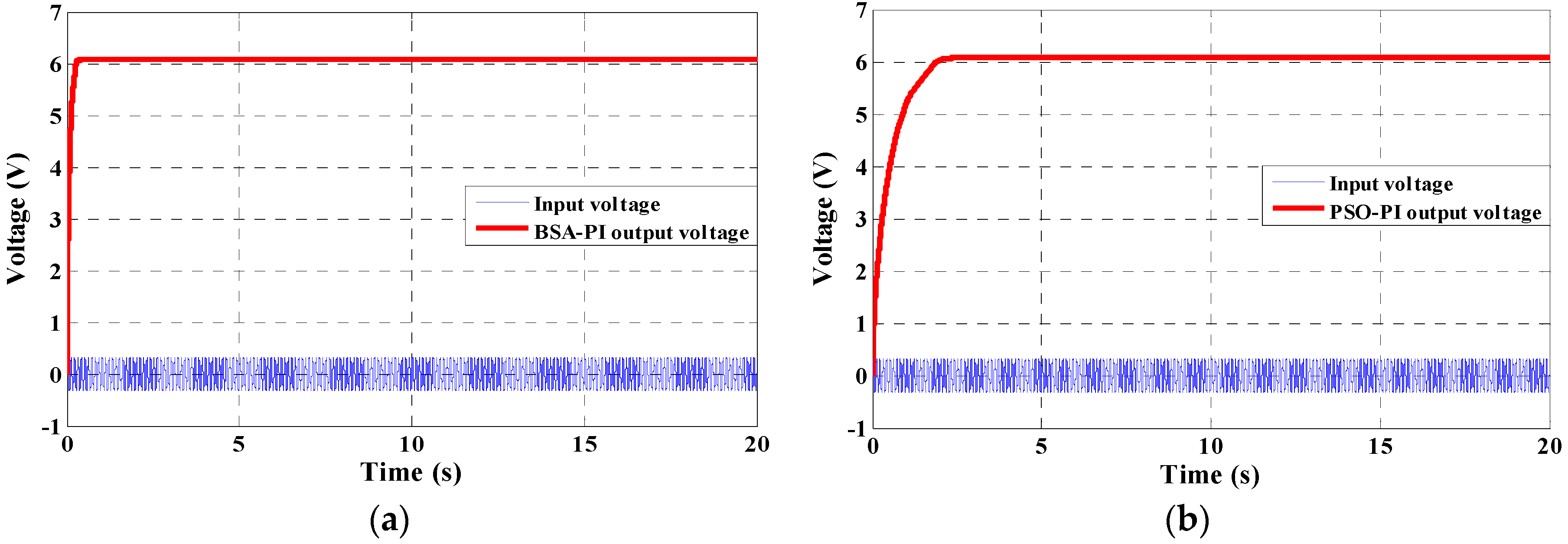
| Algorithms | Kp | Ki | Rise Time (Tr) | Settling Time (Ts) | Peak over Shoot (Po) | Steady State Error |
|---|---|---|---|---|---|---|
| BSA-PI | 0.7 | 0.03 | 0.24 s | 0.28 s | 0% | 0.1 |
| PSO-PI | 1 | 1.5 | 1.4 s | 2.1 s | 0% | 0.1 |
| Component | [36] | [37] | [38] | This Work |
|---|---|---|---|---|
| Algorithm | N/A | N/A | N/A | BSA-PI |
| Vin (Input voltage) | 0.4 V | 0.12 V | (0.25–0.4) V | 0.3 V |
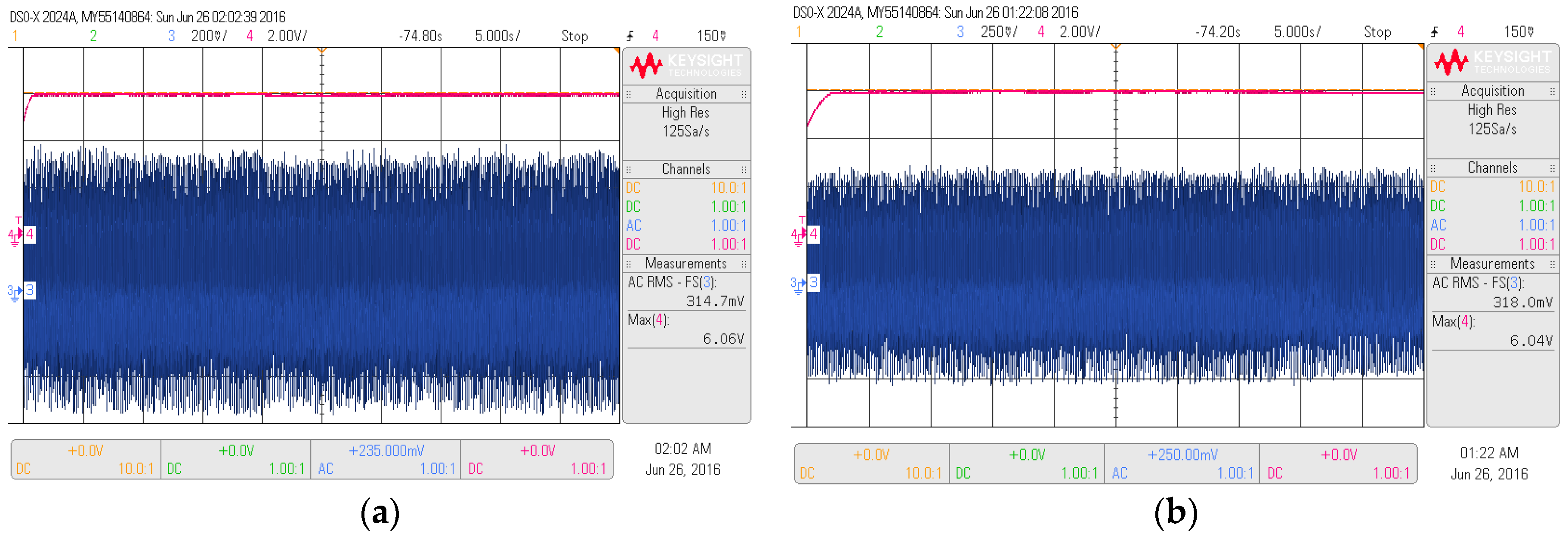
| Vo (Output voltage) | 3.3 V | 1.2 V | 3.3 V | 6.06 V |
| Switching Frequency | 50 kHz | 3 MHz | 170 kHz | 10 kHz |
| Load | 200 Ω | 10 kΩ | 30 kΩ | 1.5 MΩ, 1 MΩ, 1000 kΩ, 500 kΩ, 300 kΩ |
| Application | Energy harvesting | Energy harvesting | Low power | Micro-devices |
© 2016 by the authors. Licensee MDPI, Basel, Switzerland. This article is an open access article distributed under the terms and conditions of the Creative Commons Attribution (CC-BY) license ( http://creativecommons.org/licenses/by/4.0/).
Share and Cite
Sarker, M.R.; Mohamed, A.; Mohamed, R. A New Method for a Piezoelectric Energy Harvesting System Using a Backtracking Search Algorithm-Based PI Voltage Controller. Micromachines 2016, 7, 171. https://doi.org/10.3390/mi7100171
Sarker MR, Mohamed A, Mohamed R. A New Method for a Piezoelectric Energy Harvesting System Using a Backtracking Search Algorithm-Based PI Voltage Controller. Micromachines. 2016; 7(10):171. https://doi.org/10.3390/mi7100171
Chicago/Turabian StyleSarker, Mahidur R., Azah Mohamed, and Ramizi Mohamed. 2016. "A New Method for a Piezoelectric Energy Harvesting System Using a Backtracking Search Algorithm-Based PI Voltage Controller" Micromachines 7, no. 10: 171. https://doi.org/10.3390/mi7100171