Article

Centrifugal Step Emulsification can Produce Water in Oil Emulsions with Extremely High Internal Volume Fractions

1
Hahn-Schickard, Georges-Koehler-Allee 103, 79110 Freiburg, Germany
2
Laboratory for MEMS Applications, IMTEK — Department of Microsystems Engineering, University of Freiburg, Georges-Koehler-Allee 103, 79110 Freiburg, Germany
3
BIOSS — Centre for Biological Signalling Studies, University of Freiburg, 79110 Freiburg, Germany
*
Author to whom correspondence should be addressed.
Micromachines 2015, 6(8), 1180-1188; https://doi.org/10.3390/mi6081180
Submission received: 22 July 2015 / Revised: 11 August 2015 / Accepted: 17 August 2015 / Published: 20 August 2015
(This article belongs to the Special Issue Droplet Microfluidics: Techniques and Technologies)

Abstract

:
The high throughput preparation of emulsions with high internal volume fractions is important for many different applications, e.g., drug delivery. However, most emulsification techniques reach only low internal volume fractions and need stable flow rates that are often difficult to control. Here, we present a centrifugal high throughput step emulsification disk for the fast and easy production of emulsions with high internal volume fractions above 95%. The disk produces droplets at generation rates of up to 3700 droplets/s and, for the first time, enables the generation of emulsions with internal volume fractions of >97%. The coefficient of variation between droplet sizes is very good (4%). We apply our system to show the in situ generation of gel emulsion. In the future, the recently introduced unit operation of centrifugal step emulsification may be used for the high throughput production of droplets as reaction compartments for clinical diagnostics or as starting material for micromaterial synthesis.

Graphical Abstract

1. Introduction

The production of many small aqueous droplets in oil has attracted much attention in the recent years. Large quantities of droplets are required for many applications [1], such as DNA detection [2], controlled drug delivery [3,4], food products [5,6] and microgels [7,8]. Most of these applications require high production rates of droplets and a high monodispersity [8] (i.e., a low coefficient of variation (CV) of droplet diameters). Moreover, it is important to reach high internal volume fractions (volume of internal/dispersed phase relative to total volume of the emulsion). This is especially important for the production of porous functional polymers [9,10,11]. The internal phase ratio should be high in these applications to allow for the formation of highly porous materials after polymerization of the continuous phase. In addition, high internal volume fractions help to reduce consumption of continuous carrier medium (mostly oils) that are often expensive since special surfactants are needed for stabilization of the droplets.
The most common droplet techniques rely on flow focusing [12,13,14] or T-junctions [15,16,17,18,19], both of which require two moving phases (continuous and internal phase). Therefore, nearly all current systems need to control the flow rate of internal and continuous phase in order to produce monodisperse droplets [8,20,21,22,23,24]. To simultaneously control the flow of more than one liquid is difficult, especially when using syringe pumps or other pressure-driven systems. Another technique that overcomes this disadvantage is step emulsification [25,26] and a variation, gradient emulsification [27]. They require control over only the internal phase flow rate. However, especially for step emulsification, droplets accumulate at the nozzle and need to be moved away in order to reach high droplet generation rates. A perpendicular flow of oil has been proposed to remove the droplets from the nozzle [28]. In gradient emulsification the droplets move away from the nozzle due to capillary effect but only as long as there is a reservoir filled with oil that is sufficiently large to accommodate the droplets. Using these systems it is difficult to reach high internal volume fractions above 95%. Thus far, values ranging from 40% [22] to a maximum of 93%–95% [24] have been reported, meaning that at least 5% continuous phase are required to produce a monodispers emulsion. A recycling step of the oil is possible but difficult to introduce in the downstream preparation. Using these techniques very high production rates of droplets of up to 10 kHz have been reached [1] and continuous flow reactors have been built [22] to allow for non-stop emulsion production. Centrifugal step emulsification allows for very high internal volume fractions of up to 97.2% [29].
Here, centrifugal step emulsification is used to produce high internal volume fraction emulsions with three different aqueous phases: water, ink solution and agarose solution. The system uses centrifugal forces for the production of the emulsion via centrifugal step emulsification. In addition to this, the centrifugal force is used to remove excess oil from the emulsion to the droplet production nozzles. The process is used to demonstrate the production of gel emulsions in situ and an outlook is given on the potential of parallelization.

2. Experimental Section

The microfluidic step emulsification disks were fabricated by Hahn-Schickard Lab-on-a-Chip Design & Foundry Service [30]. Designs of the structures were first drawn using SolidWorks 2015 (Dassault Systèmes, Vélizy-Villacoublay, France) and milled in Polymethyl methacrylate (PMMA) (Maertin, Freiburg, Germany) using a Kern Evo (Kern Micro- und Feinwerktechnik GmbH & Co. KG, Eschenlohe, Germany). Quality control was done with a Zeiss AX10 microscope equipped with an AxioCam ICc1 and an Imager M2m (Zeiss, Jena, Germany). The disk was sealed using pressure sensitive adhesive tape (#900 320, HJ Bioanalytik, Erkelenz, Germany) using a customized PCS 30 lamination tool (Jakob Weiß & Söhne, Sinsheim, Germany). The foil can be peeled off and the disk resealed and reused after careful cleaning with soap and water. For emulsification Novec7500 with 2 wt % of Picosurf-1 (Dolomite, Royston, UK) was used as continuous phase. The internal phase was DNAse/RNAse free water (Thermo Fisher Scientific, Waltham, MA, USA) or 1.25% w/v low melting agarose (Fisher, Schwerte, Germany) in water or 10% v/v inkjet printer ink in water. The disk was spun in a LabDisk player prototype (for a photograph of the full system please see the Figure S1) (Qiagen Lake Constance, Stockach, Germany). The LabDisk player was equipped with a stroboscopic camera unit that could take pictures under rotation. Coefficients of variation (CV) of the droplet volume were calculated by imaging the droplet production under rotation. Images of droplets from different positions on the disk and at different times were combined in a single image and droplet sizes measured using ImageJ.

3. Results and Discussion

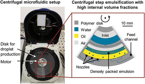
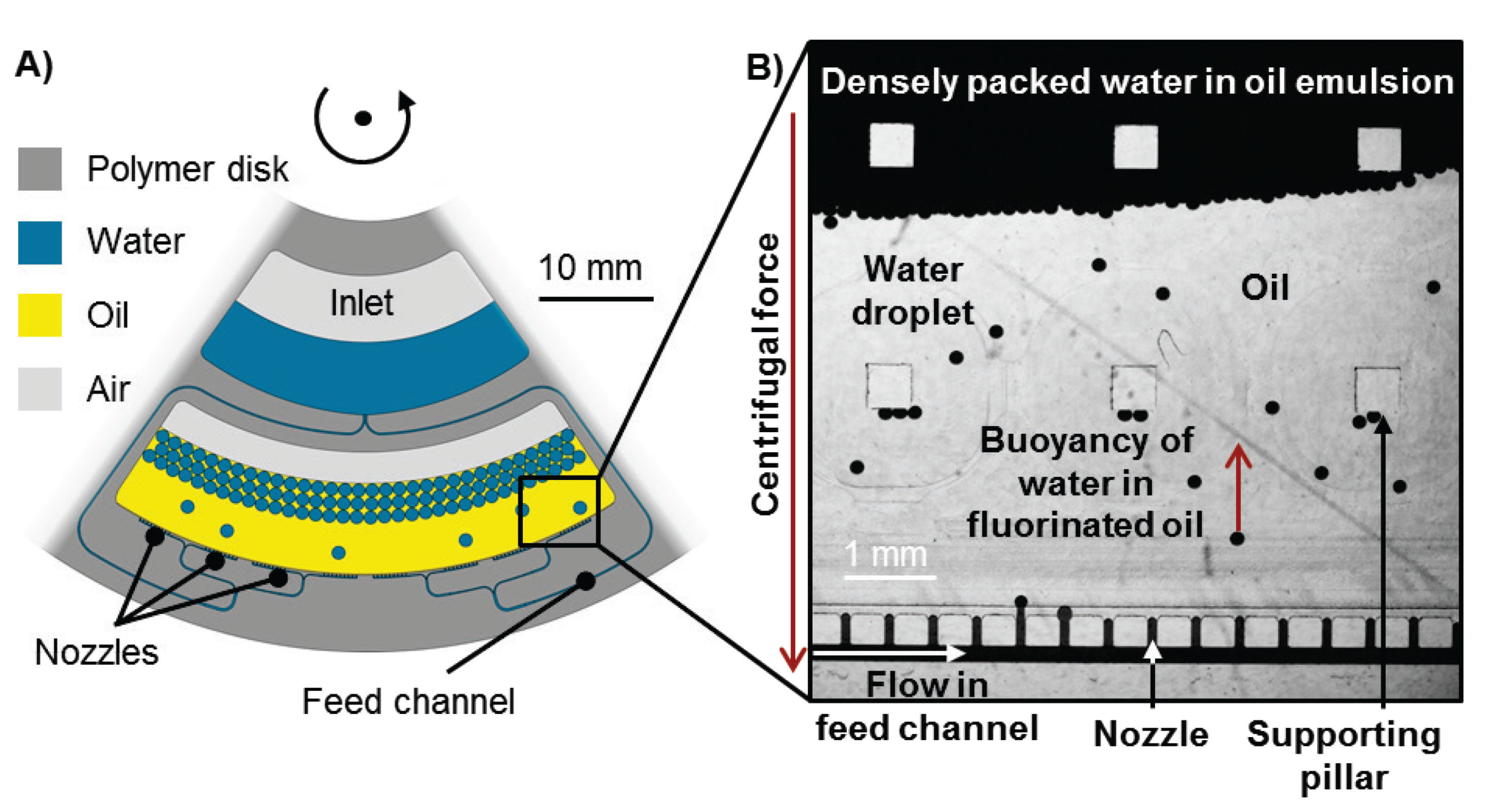
3.1. Working Principle

The system uses centrifugal step emulsification that has already been presented in detail [29]. In brief, an inlet chamber is connected to a droplet collection chamber by a channel. The connection between the channel and the chamber is called the nozzle. At the nozzle, the channel first widens in x-direction to form a terrace. This terrace is 100 µm wide and leads to a backward facing step. Here, the depth suddenly increases to 200 µm. After the structure is primed with oil, aqueous liquid is pushed into the channels by centrifugal force. At the sudden step, capillary effects lead to the formation of droplets. The size of these droplets is exclusively determined by the size of the channel and the interfacial tension. The droplets rise in the surrounding oil since the density of the oil (ρ = 1.6 g/mL) is much larger than that of water (see Figure 1B). To increase the throughput the number of nozzles was increased to 72 (for an overview of the structure see Figure 1A).
In contrast to our previous work, the nozzles are arranged in eight rows of nine nozzles, each branching off from eight feed channels (for a video of droplet production see Movie S1). Each row of nozzles is supplied with aqueous solution by a common feed channel. To feed all nozzles with liquid, the cross section of the feed channel was larger than the cross section of the nozzles (w/d: 140 × 100 µm² and 90 × 60 µm², respectively, for details compare Table S1). Since the pressure along the feed channel drops as nozzles keep branching off, the droplet production rate per nozzle decreases with increasing length of the feed channel. In order to keep droplet production rates high, the feed channels were kept relatively short and supplied through a series of splitters from a common inlet. Each of the splitters divides the channel into two daughter channels that have the same depth but half the width of the mother channel. After each splitter the daughter channel cross section is “turned” sideways by 90°, i.e., the new channel depth is decreased to the former channel width and vice versa. This strategy allows to use only two aspect ratios throughout the whole disk ( 1 : 2 and 2 : 1 ) and avoids very shallow but wide channels at the beginning. It is important to avoid wide shallow channel bends since the channel is filled with oil (in the gutters) and water under centrifugation during the experiment. The lighter water tends to detach from the radially outer radius of the bend under centrifugation due to buoyancy. This can lead to a rupture of the aqueous thread, which will in turn inhibit droplet production. After the initial backward facing step (1st step) a small area of 200 µm in depth was introduced to observe the droplets in a monolayer (see Figure 2A). In contrast to previous work, the droplet collection chamber features another step (2nd step) radially inward, further increasing the depth to 2000 µm. Thereby, a larger volume of emulsion can be accommodated in the chamber (up to 1.2 mL).
Figure 1. (a) Schematic top view of the high-throughput centrifugal step emulsification structure. The inlet chamber is located close to the center of rotation. A channel emerges from the inlet chamber and is split multiple times before leading to 8 sets of nozzles. These nozzles lead to the droplet collection chamber. Supporting pillars prevent the sealing film on top of the emulsification chamber to fall down to the bottom of the chamber during sealing. (b) Image of the production of ink emulsion in a similar setup taken under rotation. The black ink droplets can be seen rising in the surrounding fluorinated oil.
Micromachines 06 01180 g001
Figure 2. (a) Microscopic image of droplets after production in the droplet collection chamber. In the lower part of the image the feed channel and nozzles can be seen. In the middle, the droplets form a monolayer since the droplet collection chamber is shallow. In the upper part of the images many layers of droplets lie on top of each other since the chamber is very deep at this point. Therefore, no individual droplets can be seen anymore. This image was taken without centrifugal forces being applied. Since the droplets are not pushed towards the center of rotation by buoyancy in the artificial gravity field the droplets fill the whole droplet chamber. Since very little oil surrounds the droplets, they are forced to form a hexagonal pattern. This is visible in the shallow area after the 1st step, where a monolayer of droplets is formed (as opposed to the deep area, where multiple layers are stacked on top of each other). (b) Photographic image of gel emulsion with 97.2% internal phase. The gel emulsion is stable enough to turn it upside down in a 0.5 mL vial. At the bottom of the picture, the structure of individual droplets can be identified.
Micromachines 06 01180 g002

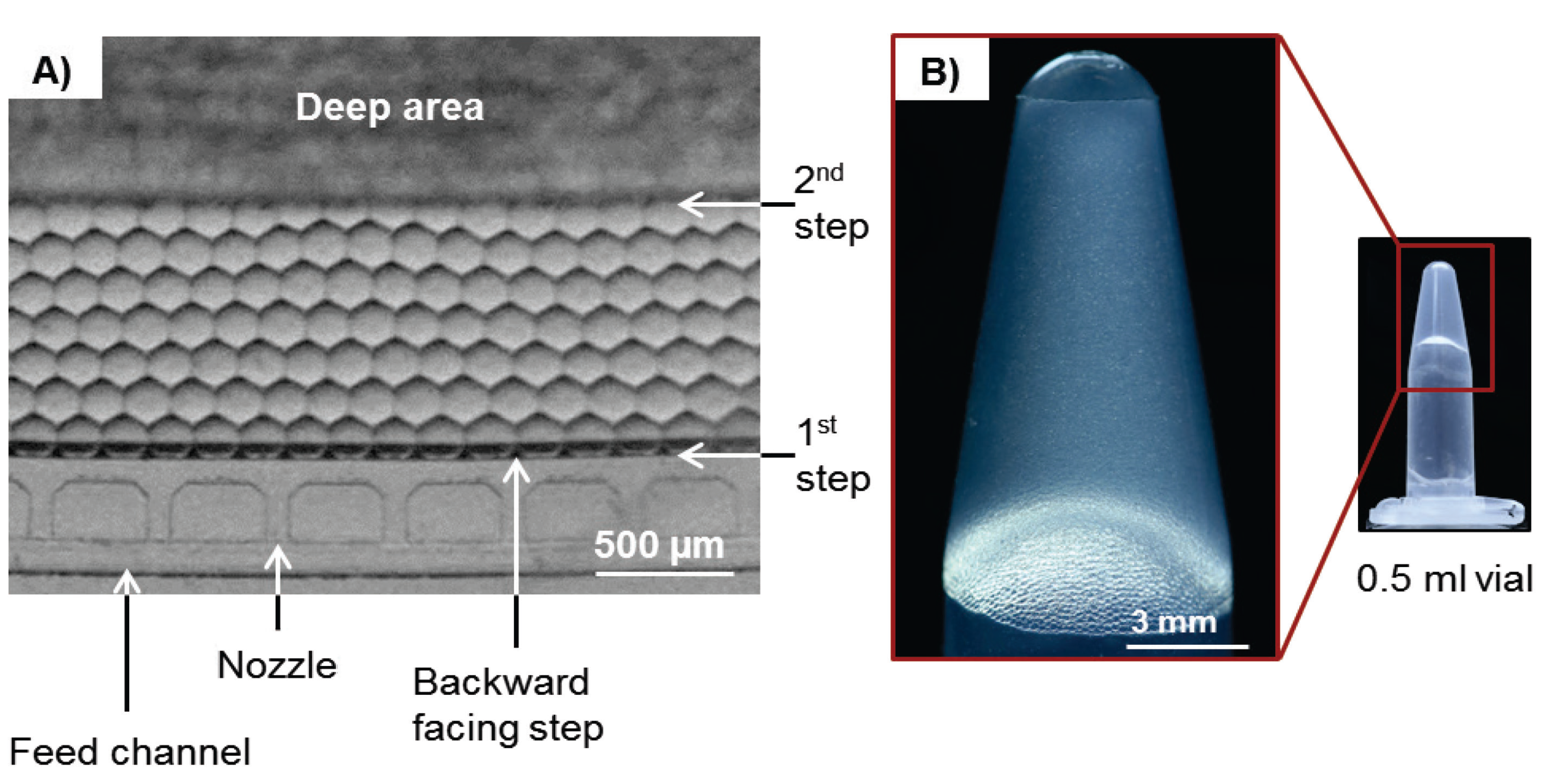
3.2. Experimental Results

The production rate of droplets at a rotational frequency of 20 Hz reaches 3700 droplets/s for 72 nozzles, measured to be 156 µm in diameter. This is equivalent to 13.5 µL/s and yields more than 1 kg per day, a range feasible for technical production. The generation speed of droplets can be changed over 3–4 orders of magnitude without changing the droplet volume. Since many applications require monodispers droplets, the CV of droplet diameters was measured and found to be <4% for the production of droplets throughout the experiment.
In order to produce emulsions with extremely high internal volume fractions, only very small amounts (10–50 µL) of carrier oil were inserted directly into the droplet collection chamber. Upon insertion of the oil into the shallow chamber, it immediately forms a thin film due to its highly wetting properties. This leads to a high surface to volume ratio, which increases the evaporation of oil to the air in the chamber. This evaporation could not be measured and, as a worst-case scenario for the calculation of the internal phase ratio, it was assumed to be zero. Any evaporation of the oil would decrease the oil volume in the final emulsion, thereby increasing the internal phase ratio.
Experiments with different parameters were performed (for an overview see Table 1). Three different aqueous components were used: water, inkjet printer ink in water (10% v/v) and low melting agarose (1.25% w/v). For the water in oil emulsions 700 µL of aqueous phase and 20 µL of oil were used and the disk was rotated at 20 Hz. Assuming no loss of oil by evaporation, internal volume fractions of at least 97.2% could be reached, without any droplet merging being observed. Another experiment was performed using only 10 µL of oil and 1000 µL of water, increasing the internal volume fraction to 99%. Spinning frequency was kept at 20 Hz. While droplet production proceeded without problems at 20 Hz throughout the experiment, the droplets close to the center merged to a single layer of water. Assuming that all of the oil is displaced from the emulsion in the parts closest to the center of rotation, the droplets begin to merge and the oil sinks to the radially outer parts of the disk to participate in continued droplet formation. When the spinning frequency is reduced to 10 Hz to avoid merging, the buoyancy of the droplets decreases. Therefore, the droplets do not pack as densely and more oil is trapped between the droplets. Droplets begin to accumulate at the nozzle, which impedes production of new droplets and leads to inhomogeneous droplet sizes.
Table 1. Overview of parameters for different gel emulsification experiments. Oil phase is Novec7500 with 2 wt % of Picosurf-1. The experiments were performed at room temperature, except for agarose, which was performed at 50 °C. Image of #1 is a monolayer on the disk with the step to deeper regions in the top part, #4 is a monolayer on the disk with the step to deeper regions in the top part, #5 is agarose droplets after gelification.
#Aqueous MediumAqueous VolumeOil VolumeInternal Volume FractionSpinning FrequencyCommentImage
1Water700 µL20 µL97.2%20 HzFunctional Micromachines 06 01180 i001
2Water1000 µL10 µL(99%)20 HzMerging of droplets observed
3Water700 µL20 µL-10 HzLow frequency leads to accumulation of droplets at nozzles. This leads to inhomogeneous droplet production
4Ink Solution700 µL20 µL97.2%20 HzFunctional Micromachines 06 01180 i002
5Agarose Solution700 µL50 µL93%20 HzFunctional Micromachines 06 01180 i003
In a separate experiment water was replaced with a solution of 10% v/v of inkjet printer ink in water. Seven-hundred microliters of ink solution and 20 µL of oil were used, spinning frequency was 20 Hz. Droplet generation proceeded without problems with an internal volume fraction of 97.2%.
For the production of agarose beads a solution of low melting agarose was prepared. Since the agarose solution needed to be kept at temperatures around 50 °C to avoid gelification of the solution, the system was heated to 50 °C using the heating system of the LabDisk Player that is based on heating with a stream of hot air. Since the evaporation of the oil (vapor pressure 2.1 kPa at 25 °C) drastically increases at elevated temperatures, 50 µL oil instead of the usual 20 µL oil were inserted into the system to compensate for possible evaporation, Seven-hundred microliters of agarose solution were used. For calculation of the internal volume fraction no evaporation was assumed yielding an internal volume fraction of 93%. The emulsification was carried out at 20 Hz and 50 °C. Afterwards the emulsion was cooled on ice to allow gelification of the agarose (see Table 1).
The very high internal volume fractions of up to 97.2% enable the in situ production of gel emulsions as can be seen in Figure 2B. Since the droplets are very densely packed with very little oil surrounding them, the internal friction increases and the emulsion starts to behave like a gel. The emulsion remained stable in test tubes at room temperature for a minimum of 6 months for all three experiments performed. Careful resuspension of the gel in additional oil is possible.

4. Conclusions

We presented a high throughput step emulsification disk that is easy to use (requiring only two pipetting steps), enables single step in situ gel emulsification [24] and requires no syringe pumps. Compared to previous systems [24] the remaining internal phase ratio was lowered by 44% reaching internal volume fractions of 97.2%. The production rate of droplets was high with a maximum of 3700 droplets/s for 72 nozzles and a low CV of 4%. The fabrication of the disk is compatible with mass production. In the future, the throughput could be increased even further by increasing the spinning frequency of the disk and adding additional nozzles to the structure. This could be done by increasing the size of the disk segment to 360°. Alternatively the disks could be stacked on top of each other, if the inlets of these stacked disks were to be connected, it would effectively result in a drum shaped cylinder with a large number of nozzles (many thousand would be possible). The size and volume of the disk could be increased to accommodate even larger volumes feasible for industrial production. The fast and easy preparation of large quantities of monodisperse droplets and particles with low carrier oil consumption demonstrated here may be of interest to the production of controlled release particles for the pharmaceutical industry and can also be applied in the food and homecare products.

Supplementary Materials

Supplementary materials can be accessed at: https://www.mdpi.com/2072-666X/6/8/1180/s1.

Acknowledgments

We gratefully acknowledge financial support from EU Framework 7 project “ANGELab” #317635. We want to thank Frank Schwemmer and Martin Trotter for helpful discussion of the microfluidic structure.

Author Contributions

Friedrich Schuler conceived, designed and performed experiments, analyzed the data and wrote the paper, Nils Paust designed the experiments, Roland Zengerle and Felix von Stetten wrote the paper.

Conflicts of Interest

The authors declare no conflict of interest.

References

  1. Shah, R.K.; Shum, H.C.; Rowat, A.C.; Lee, D.; Agresti, J.J.; Utada, A.S.; Chu, Y.L.; Kim, J.W.; Fernandez-Nieves, A.; Martinez, C.J.; et al. Designer emulsions using microfluidics. Mater. Today 2008, 11, 18–27. [Google Scholar] [CrossRef]
  2. Kang, D.K.; Ali, M.M.; Zhang, K.; Huang, S.S.; Peterson, E.; Digman, M.A.; Gratton, E.; Zhao, W. Rapid detection of single bacteria in unprocessed blood using Integrated Comprehensive Droplet Digital Detection. Nat. Commun. 2014, 5. [Google Scholar] [CrossRef] [PubMed]
  3. Tuncer Degim, I.; Celebi, N. Controlled delivery of peptides and proteins. Curr. Pharm. Des. 2007, 13, 99–117. [Google Scholar] [CrossRef]
  4. Vasiljevic, D.; Parojcic, J.; Primorac, M.; Vuleta, G. An investigation into the characteristics and drug release properties of multiple W/O/W emulsion systems containing low concentration of lipophilic polymeric emulsifier. Int. J. Pharm. 2006, 309, 171–177. [Google Scholar] [CrossRef] [PubMed]
  5. Leal-Calderon, F.; Thivilliers, F.; Schmitt, V. Structured emulsions. Curr. Opin. Colloid Interface Sci. 2007, 12, 206–212. [Google Scholar] [CrossRef]
  6. Muschiolik, G. Multiple emulsions for food use. Curr. Opin. Colloid Interface Sci. 2007, 12, 213–220. [Google Scholar] [CrossRef]
  7. Shah, R.K.; Kim, J.W.; Agresti, J.J.; Weitz, D.A.; Chu, L.Y. Fabrication of monodisperse thermosensitive microgels and gel capsules in microfluidic devices. Soft Matter 2008, 4, 2303–2309. [Google Scholar] [CrossRef]
  8. Kim, J.W.; Utada, A.S.; Fernández-Nieves, A.; Hu, Z.; Weitz, D.A. Fabrication of monodisperse gel shells and functional microgels in microfluidic devices. Angew. Chem. 2007, 119, 1851–1854. [Google Scholar] [CrossRef]
  9. Pulko, I.; Krajnc, P. High internal phase emulsion templating—A path to hierarchically porous functional polymers. Macromol. Rapid Commun. 2012, 33, 1731–1746. [Google Scholar] [CrossRef] [PubMed]
  10. Cameron, N.R. High internal phase emulsion templating as a route to well-defined porous polymers. Polymer 2005, 46, 1439–1449. [Google Scholar] [CrossRef]
  11. Solans, C.; Esquena, J.; Azemar, N. Highly concentrated (gel) emulsions, versatile reaction media. Curr. Opin. Colloid Interface Sci. 2003, 8, 156–163. [Google Scholar] [CrossRef]
  12. Gañán-Calvo, A.M. Generation of steady liquid microthreads and micron-sized monodisperse sprays in gas streams. Phys. Rev. Lett. 1998, 80, 285–288. [Google Scholar] [CrossRef]
  13. Umbanhowar, P.B.; Prasad, V.; Weitz, D.A. Monodisperse emulsion generation via drop break off in a coflowing stream. Langmuir 2000, 16, 347–351. [Google Scholar] [CrossRef]
  14. Anna, S.L.; Bontoux, N.; Stone, H.A. Formation of dispersions using “flow focusing” in microchannels. Appl. Phys. Lett. 2003, 82, 364–366. [Google Scholar] [CrossRef]
  15. Seemann, R.; Brinkmann, M.; Pfohl, T.; Herminghaus, S. Droplet based microfluidics. Rep. Prog. Phys. 2012, 75, 016601. [Google Scholar] [CrossRef] [PubMed]
  16. Christopher, G.F.; Anna, S.L. Microfluidic methods for generating continuous droplet streams. J. Phys. D Appl. Phys. 2007, 40. [Google Scholar] [CrossRef]
  17. Guillot, P.; Colin, A. Stability of parallel flows in a microchannel after a T junction. Phys. Rev. E 2005, 72, 066301. [Google Scholar] [CrossRef]
  18. Malsch, D.; Gleichmann, N.; Kielpinski, M.; Mayer, G.; Henkel, T.; Mueller, D.; van Steijn, V.; Kleijn, C.R.; Kreutzer, M.T. Dynamics of droplet formation at T-shaped nozzles with elastic feed lines. Microfluid. Nanofluid. 2010, 8, 497–507. [Google Scholar] [CrossRef]
  19. Xu, J.H.; Li, S.W.; Tan, J.; Luo, G.S. Correlations of droplet formation in T-junction microfluidic devices: From squeezing to dripping. Microfluid. Nanofluid. 2008, 5, 711–717. [Google Scholar] [CrossRef]
  20. Zeng, W.; Jacobi, I.; Beck, D.J.; Li, S.; Stone, H.A. Characterization of syringe-pump-driven induced pressure fluctuations in elastic microchannels. Lab Chip 2014, 15, 1110–1115. [Google Scholar] [CrossRef] [PubMed]
  21. Korczyk, P.M.; Cybulski, O.; Makulska, S.; Garstecki, P. Effects of unsteadiness of the rates of flow on the dynamics of formation of droplets in microfluidic systems. Lab Chip 2011, 11, 173–175. [Google Scholar] [CrossRef] [PubMed]
  22. Nisisako, T.; Torii, T. Microfluidic large-scale integration on a chip for mass production of monodisperse droplets and particles. Lab Chip 2008, 8, 287–293. [Google Scholar] [CrossRef] [PubMed]
  23. Li, W.; Young, E.W.K.; Seo, M.; Nie, Z.; Garstecki, P.; Simmons, C.A.; Kumacheva, E. Simultaneous generation of droplets with different dimensions in parallel integrated microfluidic droplet generators. Soft Matter 2008, 4, 258–262. [Google Scholar] [CrossRef]
  24. Priest, C.; Herminghaus, S.; Seemann, R. Generation of monodisperse gel emulsions in a microfluidic device. Appl. Phys. Lett. 2006, 88, 024106. [Google Scholar] [CrossRef]
  25. Mittal, N.; Cohen, C.; Bibette, J.; Bremond, N. Dynamics of step-emulsification: From a single to a collection of emulsion droplet generators. Phys. Fluid. 2014, 26, 082109. [Google Scholar] [CrossRef]
  26. Li, Z.; Leshansky, A.M.; Pismen, L.M.; Tabeling, P. Step-emulsification in a microfluidic device. Lab Chip 2015, 15, 1023–1031. [Google Scholar] [CrossRef] [PubMed]
  27. Dangla, R.; Kayi, S.C.; Baroud, C.N. Droplet microfluidics driven by gradients of confinement. Proc. Natl. Acad. Sci. USA 2013, 110, 853–858. [Google Scholar] [CrossRef] [PubMed]
  28. Sugiura, S.; Nakajima, M.; Iwamoto, S.; Seki, M. Interfacial tension driven monodispersed droplet formation from microfabricated channel array. Langmuir 2001, 17, 5562–5566. [Google Scholar] [CrossRef]
  29. Schuler, F.; Schwemmer, F.; Trotter, M.; Wadle, S.; Zengerle, R.; von Stetten, F.; Paust, N. Centrifugal step emulsification applied for absolute quantification of nucleic acids by digital droplet RPA. Lab Chip 2015, 15, 2759–2766. [Google Scholar] [CrossRef] [PubMed]
  30. Daniel, M. Lab-on-a-Chip Design + Foundry-Service. Available online: http://www.hahn-schickard.de/fertigung/lab-on-a-chip-design-foundry-service/ (accessed on 1 July 2015).

