Article

PDR/INS/WiFi Integration Based on Handheld Devices for Indoor Pedestrian Navigation

1
Department of Geomatics Engineering, University of Calgary, Calgary, AB T2N 1N4, Canada
2
GNSS Research Center, Wuhan University, 129 Luoyu Road, Wuhan 430079, China
*
Author to whom correspondence should be addressed.
Micromachines 2015, 6(6), 793-812; https://doi.org/10.3390/mi6060793
Submission received: 1 June 2015 / Revised: 15 June 2015 / Accepted: 17 June 2015 / Published: 23 June 2015
(This article belongs to the Special Issue Next Generation MEMS-Based Navigation—Systems and Applications)

Abstract

:
Providing an accurate and practical navigation solution anywhere with portable devices, such as smartphones, is still a challenge, especially in environments where global navigation satellite systems (GNSS) signals are not available or are degraded. This paper proposes a new algorithm that integrates inertial navigation system (INS) and pedestrian dead reckoning (PDR) to combine the advantages of both mechanizations for micro-electro-mechanical systems (MEMS) sensors in pedestrian navigation applications. In this PDR/INS integration algorithm, a pseudo-velocity-vector, which is composed of the PDR-derived forward speed and zero lateral and vertical speeds from non-holonomic constraints (NHC), works as an update for the INS to limit the velocity errors. To further limit the drift of MEMS inertial sensors, trilateration-based WiFi positions with small variances are also selected as updates for the PDR/INS integrated system. The experiments illustrate that positioning error is decreased by 60%–75% by using the proposed PDR/INS integrated MEMS solution when compared with PDR. The positioning error is further decreased by 15%–55% if the proposed PDR/INS/WiFi integrated solution is implemented. The average accuracy of the proposed PDR/INS/WiFi integration algorithm achieves 4.5 m in indoor environments.

Graphical Abstract

1. Introduction

Global Navigation Satellite System (GNSS) positioning systems calculate the position and velocity of GNSS receivers by means of trilateration techniques [1,2]. GNSS provides an accurate positioning solution for pedestrian navigation in open-sky environments. However, GNSS faces problems such as signal blockage and multipath in urban areas and other GNSS-challenging environments. In these cases, GNSS/INS (inertial navigation system) integrated systems are usually used for navigation applications [3,4,5]. However, GNSS/INS integrated systems cannot work well for pedestrian navigation in deep indoor environments where GNSS is totally unavailable. On the other hand, the demand for indoor navigation is quickly increasing in various applications including: health care monitoring, logistics, Location Based Services (LBS), emergency services, tourism, and people management [6]. Several different techniques have been developed for indoor navigation, such as WiFi [7,8], Bluetooth [9], near field communication (NFC) [10,11], radio-frequency identification (RFID) [12], and micro-electro-mechanical systems (MEMS) sensors [13,14]. To date, self-contained navigation systems based on MEMS sensors can be applied to different indoor applications, including mobile robot navigation [15] and pedestrian navigation [16]. There are two types of mechanizations for sensor-based pedestrian navigation: INS [17,18] and pedestrian dead reckoning (PDR) [2]. The INS mechanization calculates the position, velocity, and attitude (PVA) by integrating raw data from accelerometers and gyroscopes. This mechanization can provide 3D PVA information, however, navigation errors increase rapidly with time due to the drift characteristics of MEMS sensors.
To improve the MEMS navigation performance for pedestrians, PDR is proposed to reduce the accumulated navigation errors. PDR has four critical procedures: step detection, step/stride length estimation, heading estimation, and 2D position calculation. PDR provides a more accurate position solution than INS, without other aiding sources, because it uses fewer integration calculations. However, there are two assumptions in the typical PDR algorithm: (1) the handheld device is leveled (roll and pitch are 0 degrees), and (2) the device’s heading is kept the same as the user. Actually, the roll and pitch cannot always be 0 degrees. In this case, PDR-based heading, calculated by the direct integration of the data from the vertical gyroscope, is inaccurate. The heading estimation error will finally affect the positioning accuracy. Furthermore, the PDR navigation solution still drifts with time due to the MEMS sensor errors. Therefore, both INS and PDR require additional aiding sources, such as GNSS, WiFi and magnetometers, to reduce the navigation errors [19,20,21]. As previously discussed, GNSS is unavailable and unreliable in indoor environment. Iron materials and electronic devices indoors can easily disturb magnetometers. On the other hand, most public buildings such as universities, colleges, airports, shopping malls, and office buildings already have well-established WiFi infrastructure [7], making WiFi the main aiding resource for INS and PDR indoors.
Fingerprinting and trilateration are two main approaches for WiFi positioning [22]. Fingerprinting-based WiFi positioning usually has two operating phases: the pre-survey phase and the online positioning phase [23]. In the pre-survey phase, Received Signal Strength (RSS) values from available Access Points (APs) and position information are collected as fingerprints for creating the radio map database. In the online positioning phase, the phone’s position is estimated by comparing observed RSS values with the fingerprints in the pre-built database. Trilateration-based WiFi positioning first calculates the ranges between the phone/device and APs through the wireless signal propagation model. Then, the phone’s position is estimated through the use of trilateration [24]. Fingerprinting usually provides more accurate position solutions at the cost of survey work in the pre-survey phase.
In this paper, we propose a new algorithm, which integrates INS and PDR for MEMS inertial-sensors-based pedestrian navigation. In this algorithm, step detection and step length estimation are kept the same as the traditional PDR algorithm. Then, the step length is used to calculate the forward speed; meanwhile, non-holonomic constraint (NHC) assumes that lateral and vertical speeds are zeroes based on the fact that a moving platform cannot skid or jump. After that, the forward, lateral, and vertical speeds are combined to pseudo-velocity, which works as the velocity update for the INS to limit the velocity errors. Additionally, Zero Velocity Update (ZUPT) applies zero-velocity as an update if the object is obviously at rest. Furthermore, Zero Angular Rate Update (ZARU) applies the constant heading as the heading update if the object is obviously at rest. In the proposed algorithm of MEMS inertial-sensors-based pedestrian navigation, the attitude information from the INS potentially improves the heading estimation when compared with PDR, because it also considers the effects of the roll and pitch. ZARU can enhance the accuracy of heading estimation of the proposed system when the object is static, and further improve the whole attitude estimation. The pseudo-velocity update and ZUPT also improve the accuracy of the attitude due to the coupling of velocity and attitude errors in the INS dynamic error model. However, the heading cannot be estimated very well in the proposed PDR/INS integrated algorithm because it is weakly coupled with the velocity update. Therefore, a WiFi solution is also used in the PDR/INS/WiFi integrated system to improve the position and attitude estimation when it is accurate. In this paper, trilateration is used for WiFi positioning because it can be implemented without pre-surveys. The approximate accuracy of WiFi positioning, which is derived from the position covariance matrix in the least squares (LSQ), is used as an indicator to determine whether the WiFi position is suitable for the PDR/INS/WiFi integration. The proposed algorithms are evaluated in typical indoor scenarios. The performances of PDR, INS, the PDR/INS integration, and the PDR/INS/WiFi integration are also compared.

2. Related Works

2.1. Recent MEMS-Based Navigation Technologies

INS mechanization [17] is the typical technology used for MEMS-based navigation. In the past few years, INS mechanization has been applied to many navigation applications such as those in the studies of [4,25,26]. On the other hand, over the last decade, some algorithms based on PDR have been proposed for pedestrian navigation because it drifts slower when compared with INS as shown in [16,27,28]. Recently, PDR solutions have become practical in people’s daily use [16] because many handheld devices are equipped with inertial sensors. The main advantage of INS and PDR solutions is that they do not require additional infrastructure. However, since the navigation is based on noisy inertial sensors, navigation solutions of both PDR and INS systems drift over time [29].

2.2. Integrated Technologies for WiFi and MEMS Sensors

An indoor positioning system for pedestrians, combing WiFi fingerprinting with foot-mounted inertial and magnetometer sensors, is proposed in [30]. However, foot mounted systems are not as convenient as handheld devices for pedestrians, and the requirement of the pre-survey makes WiFi fingerprinting impractical for a large area. Research work in [20] proposes an optimized adaptive version of the mixture particle filter for integrating WiFi fingerprinting with INS, and the system was tested in a four-wheel indoor vehicle. The system focuses on the applications of indoor vehicles, and does not adopt the handheld devices. The system also requires pre-survey for fingerprinting. An advanced integration of WiFi and INS, based on a particle filter, is proposed in [31]. Nevertheless, the particle filter is not suitable for handheld devices such as smartphones due to its heavy computational load. Furthermore, a PDR/WiFi/barometer integrated system by using the AKF (adaptive Kalman filter) is proposed in [32]. The system is also based on WiFi fingerprinting and foot-mounted sensors. A maximum likelihood-based fusion algorithm that integrates the PDR and WiFi fingerprinting is proposed in [29]. The algorithm was implemented in smartphones that made the system practical, other than the pre-survey for fingerprinting. Currently, few papers have discussed the PDR/INS/WiFi integrated technique for indoor pedestrian navigation applications; therefore, this paper proposed an approach to fill this gap. The goal of this paper is to provide a practical and reliable indoor pedestrian navigation solution, based on handheld devices, by using the PDR/INS/WiFi integration.

3. Methodology

3.1. INS Mechanization in the Navigation Frame

The essential process in any inertial navigation algorithm is the INS mechanization. The INS mechanization equations integrate the specific forces and angular rates provided by accelerometers and gyroscopes to compute the PVA of an objective [33]. These equations can be presented as follows [34]:
[ r ˙ n v ˙ n C ˙ b n ] = [ D 1 v n C b n f b ( 2 Ω i e n + Ω e n n ) v n + g n C b n ( Ω i b b Ω i n b ) ]
where r n = [ φ λ h ] T is the position vector (latitude, longitude, and height) in the navigation frame. v n = [ v N v E v D ] T is the velocity vector. C b n is the transformation matrix from the body frame to the navigation frame as a function of attitude components. gn is the gravity vector in the navigation frame, Ω i b b and Ω i n b are the skew-symmetric matrices of angular velocity vectors ω i b b and ω i n b , respectively, and D−1 is a 3 × 3 matrix whose non-zero elements are functions of φ and h [33]. Refer to [33] for details of the solution and numerical implementation of the above differential equation. Both inertial sensor errors and integration errors will cause the INS solution to diverge quickly. Therefore, other sources are usually needed to aid the INS [33].

3.2. Extended Kalman Filter
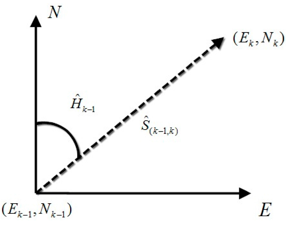
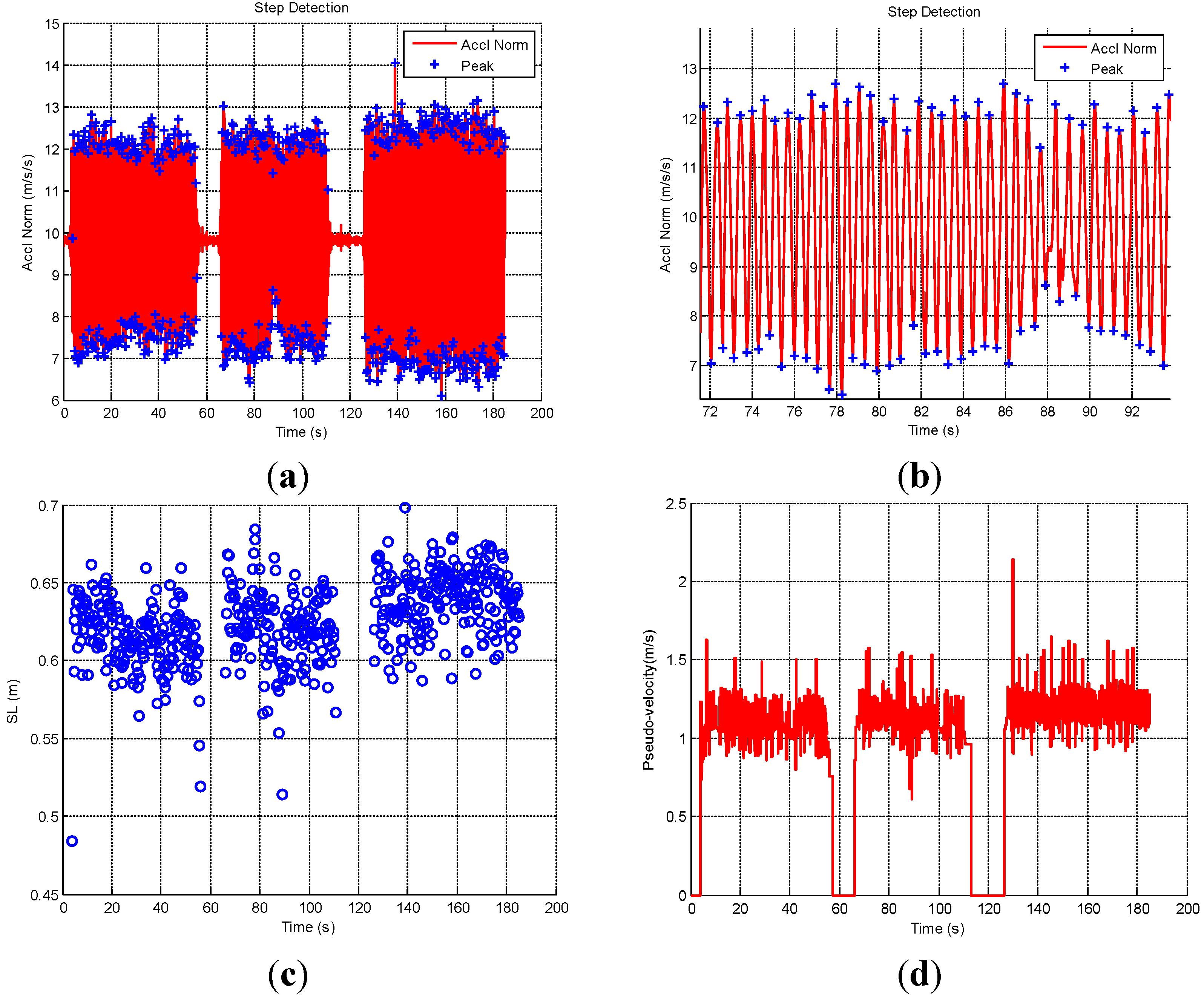
Due to the drift characteristics of MEMS sensors, the Extended Kalman Filter (EKF) is usually used to fuse other solutions such as the position and velocity from GNSS, motion constraints, and the position and velocity from PDR and WiFi. The EKF estimates the optimal state of a process by satisfying the criterion which minimizes the mean of the square errors (MMSE). When the EKF is used to fuse other sources with INS, the state vector is determined first as follows:
x = [ δ r 1 × 3 δ v 1 × 3 ε 1 × 3 d 1 × 3 b 1 × 3 ] T
where δr are position errors; δv are velocity errors; ε are attitude errors; d1×3 and b1×3 are the bias vector for gyroscopes and accelerometers. The estimated biases will be fed back into the INS mechanization.
The dynamic error model is also an important part when using the EKF for improving the INS solution. In addition to nine navigation elements in Equation (1), states of the dynamic error model include the sensor errors (three accelerometer biases and three gyro drifts). These sensor errors are usually modeled as the first order Gauss-Markov process. Therefore, the dynamic error model used in the EKF for the navigation parameters (position error, velocity error, attitude error, gyro bias and accelerometer bias) can be determined through the linearization of the INS mechanization equations and by neglecting insignificant terms in the resultant linear model. A simplified form is then obtained as [33]:
x ˙ ( t ) = ( δ r ˙ n δ v ˙ n ε ˙ n d ˙ b ˙ ) = ( D 1 δ v n D 1 D r δ v n f n × ε n ( 2 Ω i e n + Ω e n n ) δ v n + v n × ( 2 δω i e n + δω e n n ) + δ g n + C b n b Ω i n n ε n + δω i n n + C b n d α d + ω d β b + ω b )
where δrn is the position error state vector in the n-frame, δvn is the velocity error state vector in the n-frame, εn is the attitude error state vector in the n-frame, δgn is the error in the computed gravity vector in the n-frame, b and d are accelerometer bias and gyro drift vectors, α, β, ωd, ωb are the parameters for the first order Gauss-Markov process and Dr is a 3 × 3 matrix whose non-zero elements are functions of the user’s latitude, φ, and ellipsoidal height, h.
By the discretization of dynamic error model and the observation model, the discrete-time system model and observation model can be expressed as:
{ δ x k + 1 = Φ k , k + 1 δ x k + w k + 1 δ z k + 1 = H k + 1 δ x k + 1 + v k + 1
where δxk is the state vector at epoch k, Φk,k+1 is the state transition matrix from epoch k to epoch k + 1, and wk+1 is the process noise. δzk+1 is the observation misclosure vector at epoch k + 1, Hk+1 is the design matrix at epoch k + 1, and vk is the observation noise. For more knowledge about EKF for integrated navigation system, refer to [35].

3.3. PDR Algorithm

Dead Reckoning (DR) determines current vehicle position from the knowledge of the previous position and the measurements of motion direction and traveled distance [33]. DR algorithm is usually used for vehicle navigation. PDR applies the traditional DR algorithm for personal navigation applications. PDR algorithm is often applied to obtain the personal position information at each step of the personal movement. In this case, techniques are studied for step detection, and the traveled distance equals to step length. The PDR mechanization equation is given by:
E k = E k 1 + s ^ ( k 1 , k ) sin ( H ^ k 1 ) N k = N k 1 + s ^ ( k 1 , k ) cos ( H ^ k 1 )
where (Ek−1, Nk−1) and (Ek, Nk) are previous and current positions in the local level frame, s ^ ( k 1 , k ) is the estimated kth stride length, and H ^ k 1 is the estimated (k − 1)th heading. Figure 1 clearly illustrates the PDR concept. Besides the PDR mechanization, a typical PDR algorithm includes three other parts: step detection, step length estimation and heading estimation.
Usually, the cycle pattern of the acceleration norm is used to detect steps. There are several different approaches to detect steps, which include peak detection, zero crossing, auto/cross correlation and spectral analysis. In this paper, the peak detection is used for step detection due to its small computation and high successful rate. An example of peak detection is discussed in Section 4.1.
In the PDR algorithm, it is necessary to estimate the step length at each step as the forward moving distance of a person. Different practical models have been proposed for estimating the step length. In this paper, the empirical model proposed in [36] is used, which assumes the step length is proportional to the vertical movement of the human hip. The vertical movement is obtained from the largest acceleration difference in vertical direction at each step. Therefore, the equation used to estimate the step length is written as follows:
S L = a z max a z min 4 K
where azmax is the maximum value of vertical acceleration az, azmin is the minimum value of az, and K is a calibrated constant parameter.
In the PDR algorithm, gyroscopes are usually used to estimate the moving direction of a person. As we discussed before, PDR assumes that the handheld device is level (roll and pitch are 0 degrees). Sometimes, roll and pitch effects cannot be ignored. In this case, PDR-based heading, calculated by the direct integration of the data from the vertical gyroscope, is inaccurate. Therefore, PDR-derived heading is not used in our proposed PDR/INS integrated algorithm.
Figure 1. Illustration for the PDR concept.
Micromachines 06 00793 g001

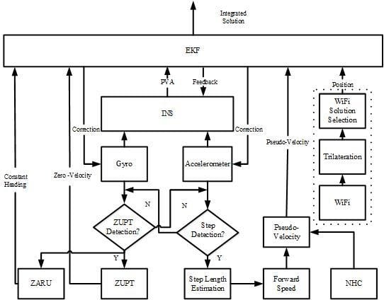
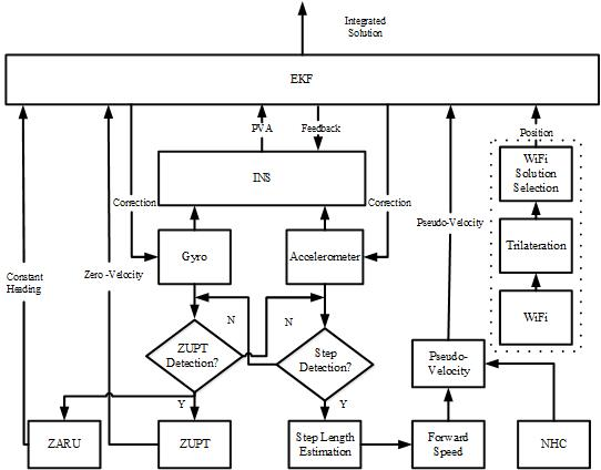
3.4. Proposed Scheme

An overview of the proposed PDR/INS/WiFi integration system on portable devices such as smartphones is illustrated in Figure 2. The part outside the dashed boxes is the proposed MEMS inertial solution based on the integration of PDR/INS and motion constraints (NHC, ZUPT, and ZARU). The part inside the dashed boxes is the WiFi positioning solution for the whole PDR/INS/WiFi integrated solution. In the traditional pedestrian navigation, raw data from MEMS inertial sensors are put into INS mechanization or PDR mechanization to estimate the user’s position. In the proposed algorithm, gyroscopes and accelerometers are used to set up the INS mechanization, detect the motion status, and set up the PDR mechanization. In this algorithm, INS, PDR, and motion constraints work together to generate a more accurate and robust pedestrian navigation solution. In Figure 2, if the step detection is successful, and the ZUPT detection is unsuccessful; the PDR step length estimation is executed to provide step length information. Next, the forward speed is derived from the estimated step length. Furthermore, NHC assumes that lateral and vertical speeds are zeroes based on the fact that a moving platform cannot skid or jump. The PDR-based forward speed and the NHC-based lateral and vertical speeds are combined to 3-axis pseudo-velocity which works as a velocity update for the INS to limit the velocity error. On the other hand, the step detection is unsuccessful, and the ZUPT detection is successful. If this is the case, ZUPT applies zero velocity as the velocity update for the INS to reduce the velocity error; ZARU is also used for the heading update for the INS to improve the attitude solution. Based on the proposed MEMS inertial-sensors-based pedestrian navigation solution, WiFi is used to further limit the drift of MEMS sensor. In the WiFi part of Figure 2, trilateration is used for estimating the WiFi positioning solution and its accuracy. The WiFi positions with good accuracy are selected as updates for the proposed sensor solution. The final proposed pedestrian navigation system is based on the integration of PDR, INS, and WiFi.
Figure 2. Block diagram of the proposed PDR/INS/WiFi integration system.
Micromachines 06 00793 g002

3.5. Proposed PDR/INS Integrated Pedestrian Navigation Solution

As previously discussed, INS and PDR are two traditional approaches for MEMS inertial-sensors-based pedestrian navigation. INS-based navigation provides complete 3D PVA. However, its error increases rapidly with time due to the drift characteristics of MEMS inertial sensors and the integrations used in the INS mechanization. On the other hand, PDR provides more accurate navigation solution because it uses step detection and step length estimation which avoid using integrations for calculating distance. However, PDR derives the heading information from the integration of the vertical gyroscope, which is inaccurate if the roll and pitch effects cannot be neglected. In this paper, we propose a PDR/INS integrated navigation solution to combine the advantages of the two schemes, and avoid the drawbacks. In the proposed PDR/INS integrated MEMS navigation solution, INS mechanization is used to process the MEMS inertial sensor data first. Next, the dynamic error model is used as the system model for the EKF estimation. At last, the PDR-based forward speed and the NHC-based lateral and vertical speeds are combined to the pseudo-velocity which works as the velocity update for the INS to limit the velocity error.
In the proposed algorithm, the gyroscopes and accelerometers measurements are used to detect the status of the pedestrian: moving or static. The status of the pedestrian is determined as “moving” if the following two conditions are satisfied: (1) the standard deviation of the angular rate norms during a certain time is larger than the threshold; and (2) steps are detected by using the approach in the section “PDR Algorithm”. On the other hand, the status of the pedestrian is determined as “static” if the following two conditions are satisfied: (1) the standard deviation of the angular rate norms during a certain time is less than the threshold; and (2) no steps are detected.
For the “moving” case, the step length estimation has been discussed in the section “PDR Algorithm”. To use the step length to provide information about the forward speed, we assume that a pedestrian’s moving speed is constant for a short time. This assumption is correct for most moving cases of pedestrians. The forward speed can be derived from the step length as follows:
v forward = S L / T step
where SL is the step length, and Tstep is the step time. NHC assumes that lateral and vertical speeds are zeroes based on the fact that a moving platform cannot skid or jump. For the pedestrian navigation, NHC can be adopted for most cases. Therefore, the pseudo-velocity-vector in the body frame can be expressed as:
v pseudo b = [ S L / T step 0 0 ] T
The pseudo-velocity-vector used for INS velocity update is the core of the PDR/INS integration. When using EKF for pseudo-velocity update, the misclosure of the velocity in the body frame is given by:
δ z = v INS b v pseudo b
where v INS b = ( C b n ) T v INS n represents the INS-based velocity in the body frame; C b n represents the transformation matrix from the body frame to navigation frame; and v INS n represents INS-based velocity in the navigation frame. Finally, the observation model for the pseudo-velocity-vector update is expressed in:
δ v b = H v b δ x + v v b
where v v b represents the measurement white noise; H v b represents the corresponding design matrix which can be expressed as:
H v b = [ 0 3 × 3 ( C b n ) T ( C b n ) T V n 0 3 × 6 ]
where Vn is the skew-symmetric matrix of vn.
If “static” is detected, ZUPT and ZARU are used as the updates for the INS to limit the navigation error. The ZUPT-based zero velocity vector in the body frame is given by:
v ZUPT b = [ 0 0 0 ] T
Similar to the pseudo-velocity vector, the ZUPT-based zero velocity vector is used as the velocity update for the INS. If the pedestrian is detected as “static”, the pedestrian heading is unchanging based on ZARU. Therefore, misclosure of the heading for the INS heading update is given by:
δ z = ψ INS ψ pre-stored
where ψINS is the INS-based heading; and ψpre-stored is the pre-stored heading of the last epoch before the “static” is detected. Finally, the observation model for the heading update is expressed in:
H ψ = [ 0 1 × 6 ψ / ε N ψ / ε E ψ / ε D 0 1 × 6 ]
For details of ψ / ε N , ψ / ε E , and ψ / ε D , please refer to [37].

3.6. Proposed PDR/INS/WiFi Integrated Indoor Pedestrian Navigation Solution

To further improve the navigation performance, WiFi is also used in the integrated system if it is available. Both trilateration-based and fingerprinting-based WiFi positioning solutions can be used as updates in the loosely-coupled integration. In this research, trilateration is selected for WiFi positioning for the following two reasons: (1) it requires less efforts to build the database; and (2) the memory cost for trilateration-based database is much less than fingerprinting-based database. However, a trilateration-based WiFi solution can be noisy due to the complex characteristics of an indoor environment. Therefore, in the integrated system, it is significant to use an approach to select accurate WiFi positions. It is fortunate that variances of WiFi positions are estimated in the state covariance matrix of the LSQ. Although these variances are not perfectly estimated, they still can be used as a rough indicator for selecting the WiFi positions for the integration. In this research, WiFi positions with variances less than 20 m2 are chosen as the updates for the MEMS sensors. The misclosure of the WiFi-based position measurements is given by:
δ z WiFi = ( [ φ λ h ] MEMS [ φ λ h ] WiFi ) [ M + h ( N + h ) cos φ 1 ] T
where φMEMS, λMEMS, and hMEMS are MEMS navigation solution estimated latitude, longitude, and altitude; φWiFi, λWiFi, and hWiFi are WiFi-based latitude, longitude, and altitude. M is the meridian radius of the earth’s curvature; and N is the prime vertical radius of the earth’s curvature. The observation equation for the WiFi position measurements is formulated as:
δ z WiFi = H WiFi δ x + v WiFi
where vWiFi is the measurement white noise of the WiFi positions; HWiFi is the corresponding design matrix, which can be expressed as:
H WiFi = [ ( M + h ) 0 0 0 ( N + h ) cos φ 0 0 0 1 0 3 × 12 ]
The covariance matrix, RWiFi, for the WiFi-based position measurements is given by:
R WiFi = d i a g ( [ σ l a t 2 σ l o n 2 σ a l t 2 ] )
where σ l a t 2 , σ l o n 2 and σ a l t 2 represent the variances of [ φ λ h ] WiFi T in meters. diag returns a square diagonal matrix with the elements of vector [ σ l a t 2 σ l o n 2 σ a l t 2 ] on the main diagonal.

4. Results

To evaluate the performance of the proposed pedestrian navigation algorithms, several experiments were performed by three pedestrians. Three different smartphones that contain an accelerometer triad, a gyroscope triad and a WiFi transreceiver were used to collect the experimental data. Different pedestrians collected data with various smartphones on three experimental trajectories in building E (about 120 m × 40 m), as shown in Figure 3. Two tasks were carried out in the field tests. The first part validates the performance of the proposed PDR/INS integrated MEMS pedestrian navigation algorithm. This section also compares the proposed MEMS solution with traditional PDR and INS algorithms. The second part shows the performance of the proposed PDR/INS/WiFi integration algorithm.
Figure 3. Three experimental trajectories in building E (about 120 m × 40 m). (a) Trajectory I; (b) Trajectory II; (c) Trajectory III.
Micromachines 06 00793 g003

4.1. PDR/INS Integrated MEMS Pedestrian Navigation Algorithm

This section illustrates the performance of the proposed PDR/INS integrated MEMS pedestrian navigation algorithm by using Trajectory I. Two other trajectories were also used to test the performance of proposed MEMS navigation solution, which are summarized in the next section. The proposed PDR/INS integrated MEMS solution, PDR solution, and the reference trajectory in experimental Trajectory I are shown in Figure 4. In Figure 4, the maximum navigation errors of the proposed method and traditional PDR are about 12 m and 34 m, respectively. This outcome shows that the proposed method is more accurate than the PDR. The average heading drift of the proposed method is also smaller than the PDR.
Figure 4. Trajectories of PDR, PDR/INS integrated MEMS solution, and the reference.
Micromachines 06 00793 g004
The velocity solution of the proposed algorithm is shown in Figure 5a. Figure 5a clearly shows the user’s moving status: (a) keeps static (ZUPT), (b) walks west, (c) keeps static (ZUPT), (d) walks west, (e) walks north, (f) walks east, (g) keeps static (ZUPT), and (h) walks east. The moving trend fits the trajectory in Figure 4. The moving speed is in the typical range of a normal person. The pseudo-velocity update and ZUPT play important roles on accurately estimating a user’s velocity. Without the pseudo-velocity update and ZUPT, the estimated velocity and position solution drifts quickly. The attitude solution of the proposed method is shown in Figure 5b. Roll and pitch angles are between −10 and 10 degrees in this trajectory. The estimated azimuth trend is (a) about −90 degrees, (b) about 0 degrees, and (c) about 100 degrees. The true azimuth trend is (a) −90 degrees, (b) 0 degrees, and (c) 90 degrees. The estimated azimuth from the proposed method is close to the true azimuth.
The results of the step detection, step length estimation, and pseudo-velocity are shown in Figure 6. In Figure 6a,b, acceleration norm and detected peaks are described by “−” and “+”. Figure 6b zooms in on some parts of the trajectory which show that the step detection algorithm can successfully detect the peaks and steps. The step length estimation result is shown in Figure 6c. The user’s step length is around 0.64 m as shown in this figure. The step-length-derived pseudo-velocity is shown in Figure 6d. The pseudo-velocity is calculated from the step length. The average velocity of this user is about 1.2 m/s.
To illustrate the performance of the proposed PDR/INS integrated MEMS navigation solution, results of the stand-alone PDR and INS are also shown in this paper. Pure PDR results are shown in Figure 4 and Figure 7. As we discussed before, the maximum navigation error of PDR is about 32 m in Figure 4, which is worse than the proposed method. In Figure 7, the azimuth error, which is the main error for the whole trajectory, reaches 20 degrees by the end of the trajectory.
Results of the pure INS algorithm are shown in Figure 8. Figure 8a shows the horizontal trajectory by using pure INS algorithm. The maximum drift reaches up to 73 km at the end of the end of the trajectory. That’s because MEMS sensors in smartphones are low cost, and their errors accumulate with time quickly. The pure INS algorithm cannot provide an accurate navigation solution for pedestrians by using handheld devices. The INS velocity solution is shown in Figure 8b. In this figure, it is clear that the velocity solution are not located in the typical range of pedestrian walking velocity. The velocity drifts to several hundred meters per second by the end of the trajectory. Figure 8c shows the attitude solution from the INS algorithm. The estimated roll and pitch can reach about ± 50 degrees sometimes, which highly drift from the true roll and pitch range (i.e., between −10 and 10 degrees). The estimated heading also drifts from the true value when compared with the reference trajectory in Figure 4. Figure 8 shows that estimated position, velocity, and attitude all highly drift from true values by using pure INS algorithm.
Figure 5. The solution of the proposed PDR/INS integrated MEMS solution. (a) Velocity; (b) Attitude.
Micromachines 06 00793 g005
Figure 6. Results of the step detection and step length estimation. (a) Step detection for the whole trajectory; (b) Zoom-in of some parts of step detection for the trajectory; (c) Result of step length estimation; (d) Result of pseudo-velocity from step length.
Micromachines 06 00793 g006
Figure 7. Results of PDR horizontal velocity and azimuth.
Micromachines 06 00793 g007
Figure 8. INS navigation solution. (a) Trajectory; (b) Velocity; (c) Attitude.
Micromachines 06 00793 g008

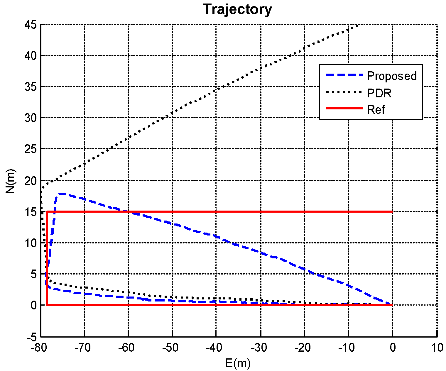
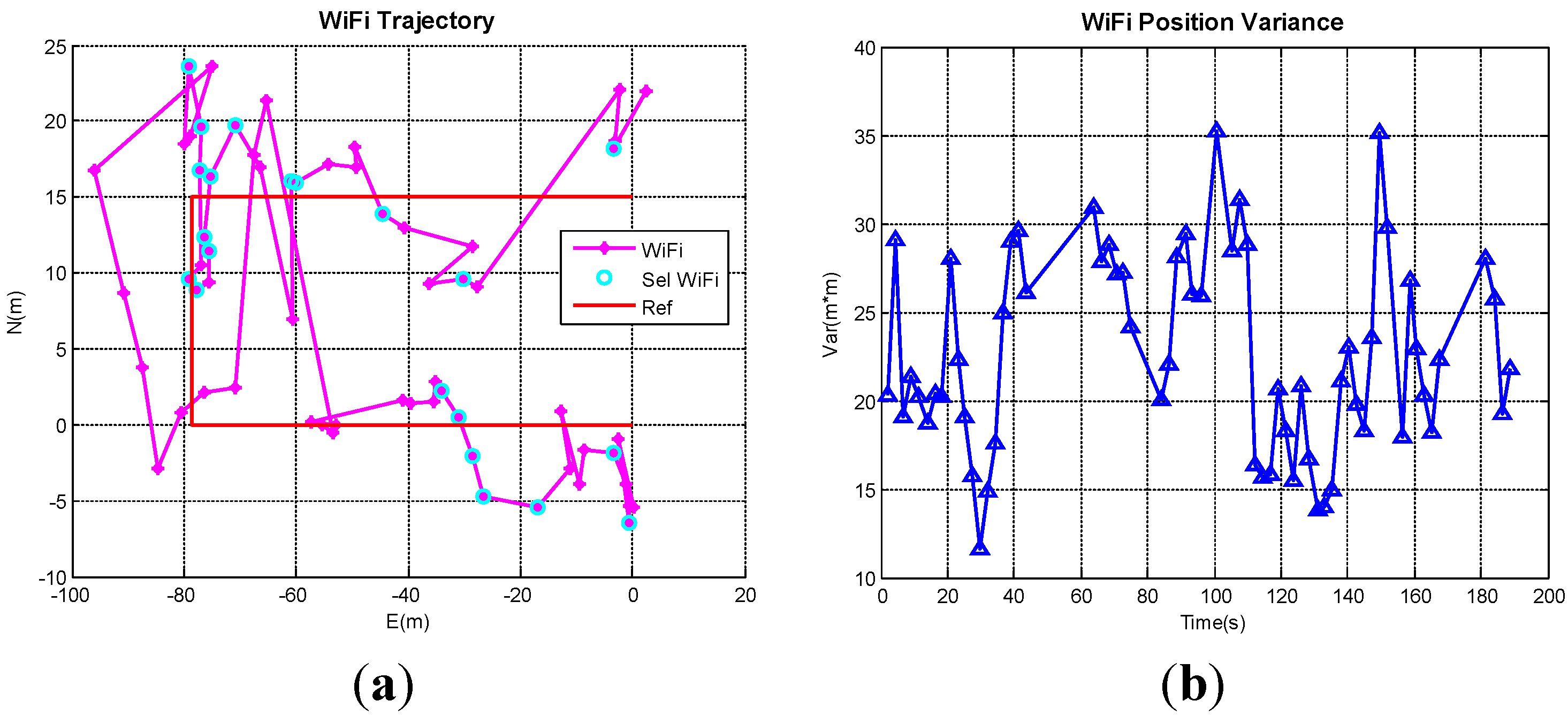
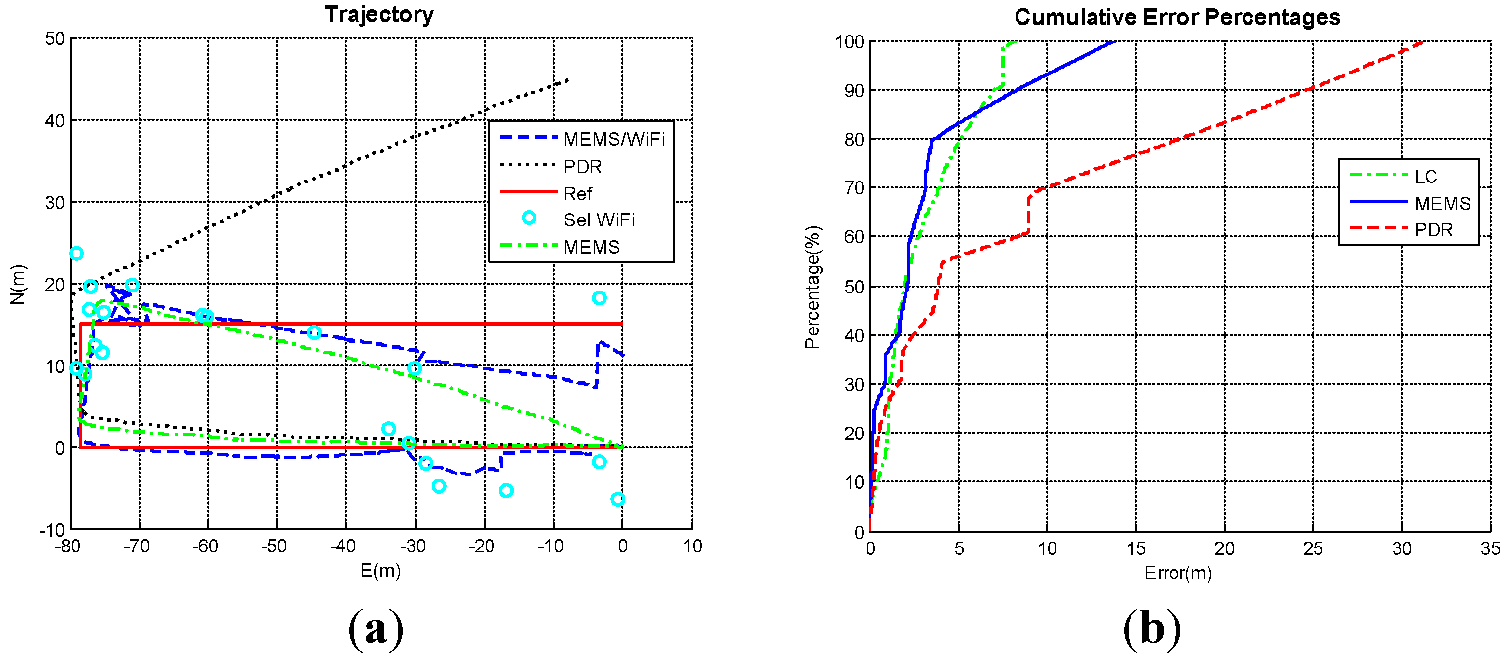
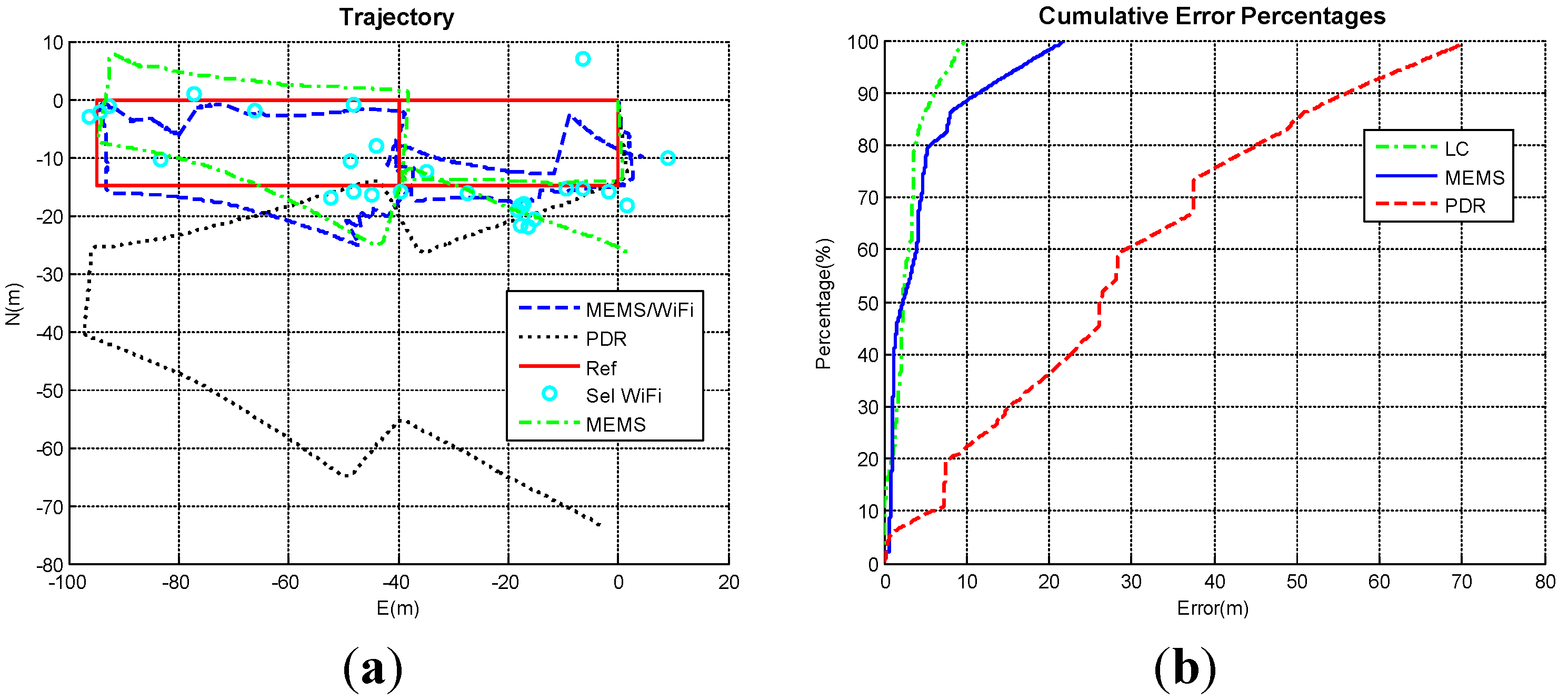
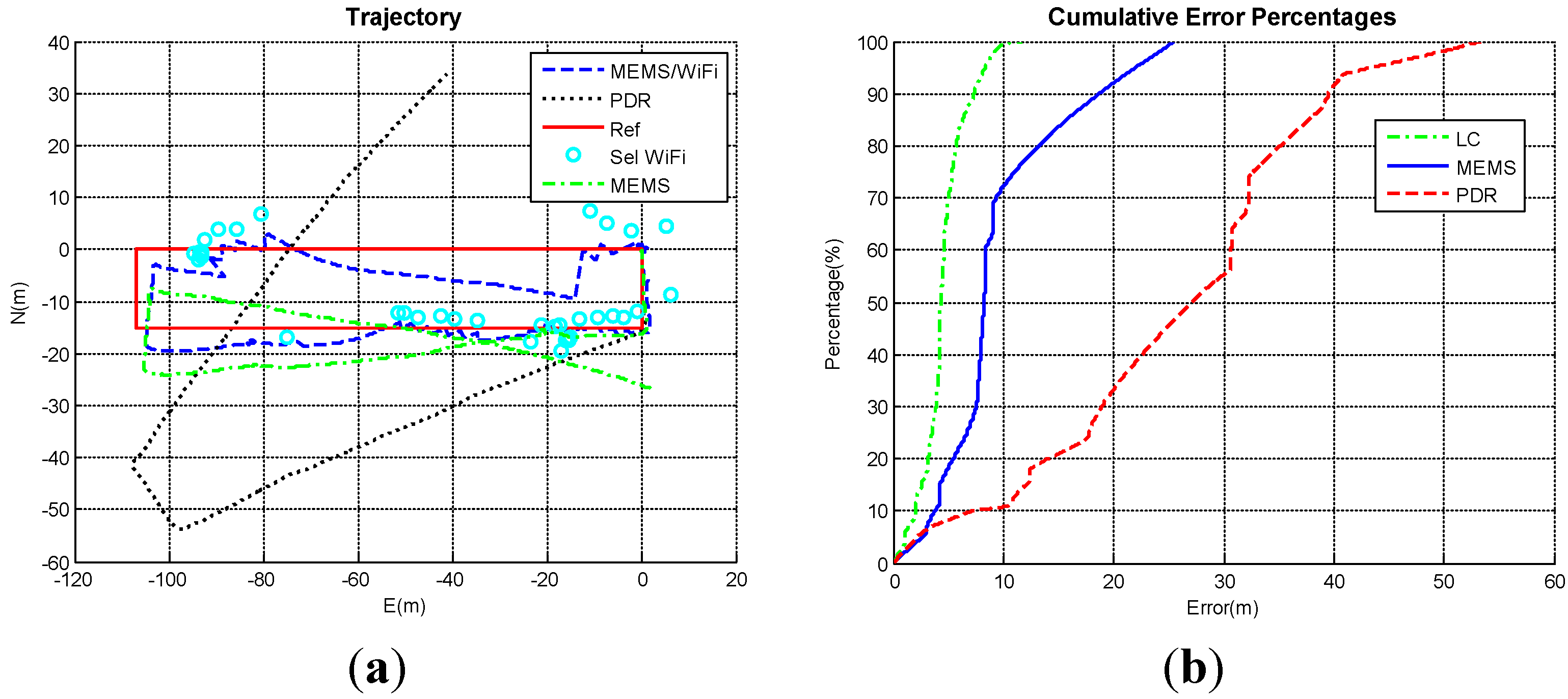
4.2. Proposed PDR/INS/WiFi Integrated Indoor Pedestrian Navigation Solution

The results (position and variance) of trilateration-based WiFi positioning of Trajectory I are shown in Figure 9. The trilateration algorithm relies on the propagation model, which is affected by several factors such as multipath and fading characteristics. Therefore, it is usually not as accurate as the fingerprinting algorithm for WiFi positioning. However, trilateration does not consume much time and labour to build and maintain a database like fingerprinting. The results contain very large errors reaching 15 m at many points. To improve the performance, some WiFi positions with large variances are left out of the integration. In this research, WiFi positions with variances less than 20 m2 are selected for integration as shown in Figure 9a. The threshold, 20 m2, is obtained by field tests. In Figure 9a, “Sel WiFi” represents the selected WiFi positions with variances less than 20 m2.
Navigation results of PDR, the proposed MEMS solution, and WiFi/MEMS integration (Trajectory I: Pedestrian 1, Smartphone A) are shown in Figure 10. The trajectory of the proposed integration of MEMS/WiFi (also called PDR/INS/WiFi) in Trajectory I is shown as the “blue dash line” in Figure 10a. This trajectory is taken by “Pedestrian 1” using “Smartphone A”. The proposed MEMS solution, PDR, and the reference are shown as a “green dash dot line”, “black dot line”, and “red solid line”, respectively. The proposed MEMS solution drifts less than the PDR solution. Selected WiFi positions are also shown as “circles” in Figure 10a. With the help of the selected WiFi positions, the integrated MEMS/WiFi solution drifts less than the proposed MEMS solution as shown in Figure 10a. The integrated MEMS/WiFi solution is also better than the WiFi solution when one compares Figure 9a with Figure 10a. The cumulative error percentages of PDR, the proposed MEMS solution, and WiFi/MEMS integration in Trajectory I are shown in Figure 10b. In this figure, The “LC” represents the WiFi/MEMS integration. The positioning performance of different algorithms in Trajectory I are depicted in Table 1. As shown in Figure 10b and Table 1, WiFi/MEMS integration has the best navigation performance, and the PDR has the worst navigation performance.
Figure 9. Trilateration-based WiFi positioning solution. (a) WiFi trajectory; (b) Variances of WiFi positions.
Micromachines 06 00793 g009
Figure 10. Navigation results of PDR, the proposed MEMS solution, and WiFi/MEMS integration (Trajectory I: Pedestrian 1, Smartphone A). (a) Trajectories; (b) Cumulative error percentages.
Micromachines 06 00793 g010
Table 1. Positioning performance of different algorithms in Trajectory I.
AlgorithmError (m)
MaximumMinimumMeanRMS
PDR31.480.138.4412.57
MEMS (PDR/INS)13.930.252.914.40
MEMS/WiFi Integration8.220.212.913.73
Navigation results of PDR, the proposed MEMS solution, and WiFi/MEMS integration (Trajectory II: Pedestrian 2, Smartphone B) are shown in Figure 11. The trajectory of the proposed MEMS/WiFi integration is shown as the “blue dash line” in Figure 11a as taken by “Pedestrian 2” using “Smartphone B”. Similar to Trajectory I, the proposed MEMS solution drifts less than the PDR solution, and the integrated MEMS/WiFi solution drifts less than the MEMS solution as shown in Figure 11a. The results of trilateration-based WiFi positioning in Trajectory II are shown in Figure 12. The integrated MEMS/WiFi solution also performs better than the WiFi solution when comparing Figure 11a with Figure 12. The cumulative error percentages of PDR, the proposed MEMS solution, and WiFi/MEMS integration in the second trajectory are shown in Figure 11b, and the positioning performance of different algorithms for Trajectory II are depicted in Table 2. In Trajectory II, the WiFi/MEMS integrated system improves about 3.5 m (RMS) when compared with the MEMS solution, which is better than in Trajectory I (0.7 m). This is probably because the MEMS solution drifts more in Trajectory II due to a longer walking period.
Figure 11. Navigation results of PDR, the proposed MEMS solution, and WiFi/MEMS integration (Trajectory II: Pedestrian 2, Smartphone B). (a) Trajectories; (b) Cumulative error percentages.
Micromachines 06 00793 g011
Figure 12. WiFi trajectory (Trajectory II).
Micromachines 06 00793 g012
Table 2. Positioning performance of different algorithms in Trajectory II.
AlgorithmError (m)
MaximumMinimumMeanRMS
PDR75.030.1427.9234.00
MEMS (PDR/INS)27.590.525.728.28
MEMS/WiFi Integration12.210.484.174.87
Navigation results of PDR, the proposed MEMS solution, and WiFi/MEMS integration (Trajectory III: Pedestrian 3, Smartphone C) are shown in Figure 13. The third trajectory of the proposed MEMS/WiFi integration is shown as the “blue dash line” in Figure 13a as taken by “Pedestrian 3” using “Smartphone C”. Similar to Trajectory I and Trajectory II, the proposed MEMS solution drifts less than the PDR solution, and the integrated MEMS/WiFi solution drifts even less than the MEMS solution as shown in Figure 13a. The results of trilateration-based WiFi positioning in Trajectory III are shown in Figure 14. The integrated MEMS/WiFi solution is also better than the WiFi-only solution when comparing Figure 13a with Figure 14. The cumulative error percentages of PDR, the proposed MEMS solution, and the WiFi/MEMS integration of the third trajectory are shown in Figure 13b, and the positioning performance of different algorithms for Trajectory III are depicted in Table 3.
Figure 13. Navigation results of PDR, the proposed MEMS solution, and WiFi/MEMS integration (Trajectory III: Pedestrian 3, Smartphone C). (a) Trajectories; (b) Cumulative error percentages.
Micromachines 06 00793 g013
Figure 14. WiFi trajectory (Trajectory III).
Micromachines 06 00793 g014
Table 3. Positioning performance of different algorithms in Trajectory III.
AlgorithmError (m)
MaximumMinimumMeanRMS
PDR53.490.0525.3528.08
MEMS (PDR/INS)25.510.019.5511.02
MEMS/WiFi Integration11.660.014.494.90
The positioning performance in three trajectories is summarized in Table 4. In Table 4, the average position errors of the proposed PDR/INS/WiFi integration algorithm for all the three trajectories are less than 4.5 meters. Furthermore, the positioning error is decreased by 60%–75% by using the proposed PDR/INS integrated MEMS solution when compared with PDR. The positioning error is further decreased by 15%–55% if the proposed PDR/INS/WiFi integrated solution is implemented.
Table 4. Summary of positioning performance in three trajectories.
AlgorithmMean Error (m)RMS Error (m)
Trajectory ITrajectory IITrajectory IIITrajectory ITrajectory IITrajectory III
PDR8.4427.9225.3512.5734.0028.08
MEMS (PDR/INS)2.915.729.554.408.2811.02
MEMS/WiFi Integration2.914.174.493.734.874.90

5. Conclusions

A new low-cost MEMS navigation solution for pedestrians is presented in this paper. The proposed navigation solution utilizes traditional INS and PDR mechanizations to introduce a PDR/INS integrated navigation solution. In this algorithm, PDR-based forward speed and NHC-based lateral and vertical speeds are combined to the pseudo-velocity which worked as the velocity update for the INS. ZUPT and ZARU were also used as the updates in the EKF if they are available. These updates effectively reduced the accumulated position, velocity, and attitude errors when there are no other aiding sources. Furthermore, selected trilateration-based WiFi positions are used as updates for the PDR/INS integrated system to limit the drift of the proposed MEMS inertial-sensors-based pedestrian navigation solution, and finally to build the PDR/INS/WiFi integrated scheme for indoor pedestrian navigation.
The proposed system was tested in indoor pedestrian experiments to demonstrate its performance, accuracy, and ability in providing an effective solution. By testing the proposed system with different pedestrians and various smartphones, the performance of the proposed system does not rely on pedestrians or smartphones. The experiments demonstrate that positioning error of the proposed PDR/INS integrated MEMS solution decreases by 60%–75% when compared with PDR. The positioning error is further decreased by 15%–55% if using the proposed PDR/INS/WiFi integrated solution. The experimental results also show that the average accuracy of the proposed PDR/INS/WiFi integration algorithm achieves 4.5 m indoors.

Acknowledgments

This work was supported in part by the research funding from Naser El-Sheimy. The first author (Yuan Zhuang) would also thank the Alberta Innovates Technology Futures (AITF) for the Graduate Student Scholarship.

Author Contributions

Yuan Zhuang and Naser El-Sheimy conceived and designed the research; Yuan Zhuang, Haiyu Lan, and You Li performed the research; Yuan Zhuang, Haiyu Lan, and You Li analyzed the data; Naser El-Sheimy contributed materials; Yuan Zhuang and You Li wrote the paper.

Conflicts of Interest

The authors declare no conflict of interest.

References

  1. Kaplan, E.D.; Hegarty, C.J. Understanding GPS: Principles and Applications; Artech House Publishers: Norwood, MA, USA, 2006. [Google Scholar]
  2. He, Z.; Renaudin, V.; Petovello, M.G.; Lachapelle, G. Use of high sensitivity GNSS receiver doppler measurements for indoor pedestrian dead reckoning. Sensors 2013, 13, 4303–4326. [Google Scholar] [CrossRef] [PubMed]
  3. Nassar, S.; El-Sheimy, N. A combined algorithm of improving INS error modeling and sensor measurements for accurate INS/GPS navigation. GPS Solut. 2006, 10, 29–39. [Google Scholar] [CrossRef]
  4. Sadi, F.; Klukas, R. New jump trajectory determination method using low-cost mems sensor fusion and augmented observations for GPS/INS integration. GPS Solut. 2013, 17, 139–152. [Google Scholar] [CrossRef]
  5. Niu, X.; Li, Y.; Zhang, H.; Cheng, Y.; Shi, C. Observability analysis of non-holonomic constraints for land-vehicle navigation systems. J. Glob. Position. Syst. 2012, 11, 80–88. [Google Scholar] [CrossRef]
  6. Li, Y.; Georgy, J.; Niu, X.; Li, Q.; El-Sheimy, N. Autonomous calibration of MEMS gyros in consumer portable devices. IEEE Sens. J. 2015, 15, 4062–4072. [Google Scholar] [CrossRef]
  7. Zhuang, Y.; Syed, Z.; Georgy, J.; El-Sheimy, N. Autonomous smartphone-based WiFi positioning system by using access points localization and crowdsourcing. Pervasive Mob. Comput. 2015, 18, 118–136. [Google Scholar] [CrossRef]
  8. Zhuang, Y.; Wright, B.; Syed, Z.; Shen, Z.; El-Sheimy, N. Fast WiFi access point localization and autonomous crowdsourcing. In Proceedings of the Ubiquitous Positioning Indoor Navigation and Location Based Service (UPINLBS), Corpus Christ, TX, USA, 20–21 November 2014; pp. 272–280.
  9. Zhao, X.; Xiao, Z.; Markham, A.; Trigoni, N.; Ren, Y. Does BTLE measure up against WiFi? A comparison of indoor location performance. In Proceedings of the 20th European Wireless Conference, Barcelona, Spain, 14–16 May 2014; pp. 1–6.
  10. Ozdenizci, B.; Coskun, V.; Ok, K. NFC internal: An indoor navigation system. Sensors 2015, 15, 7571–7595. [Google Scholar] [CrossRef] [PubMed] [Green Version]
  11. Cassimon, D.; Engelen, P.-J.; Yordanov, V. Compound real option valuation with phase-specific volatility: A multi-phase mobile payments case study. Technovation 2011, 31, 240–255. [Google Scholar] [CrossRef] [Green Version]
  12. Ruiz, A.J.; Granja, F.S.; Prieto Honorato, J.C.; Rosas, J.I. Accurate pedestrian indoor navigation by tightly coupling foot-mounted IMU and RFID measurements. Instrum. Meas. IEEE Trans. 2012, 61, 178–189. [Google Scholar] [CrossRef]
  13. Yuan, X.; Yu, S.; Zhang, S.; Wang, G.; Liu, S. Quaternion-based unscented Kalman filter for accurate indoor heading estimation using wearable multi-sensor system. Sensors 2015, 15, 10872–10890. [Google Scholar] [CrossRef] [PubMed]
  14. Liu, C.; Zhang, S.; Yu, S.; Yuan, X.; Liu, S. Design and analysis of gyro-free inertial measurement units with different configurations. Sens. Actuators A Phys. 2014, 214, 175–186. [Google Scholar] [CrossRef]
  15. Lee, Y.-C.; Yu, W.; Cho, J.-I. Adaptive localization for mobile robots in urban environments using low-cost sensors and enhanced topological map. In Proceedings of the 15th International Conference on Advanced Robotics (ICAR), Tallinn, Estonia, 20–23 June 2011; pp. 569–575.
  16. Zhuang, Y.; Chang, H.W.; El-Sheimy, N. A MEMS multi-sensors system for pedestrian navigation. In Proceedings of the China Satellite Navigation Conference (CSNC), Wuhan, China, 4 May 2013; pp. 651–660.
  17. Titterton, D.H.; Weston, J.L. Strapdown Inertial Navigation Technology, 2nd ed.; Institution of Engineering and Technology: Stevenage, UK, 2004. [Google Scholar]
  18. Li, Y.; Niu, X.; Zhang, Q.; Zhang, H.; Shi, C. An in situ hand calibration method using a pseudo-observation scheme for low-end inertial measurement units. Meas. Sci. Technol. 2012, 23, 105104. [Google Scholar] [CrossRef]
  19. Chiang, K.-W.; Chang, H.-W. Intelligent sensor positioning and orientation through constructive neural network-embedded INS/GPS integration algorithms. Sensors 2010, 10, 9252–9285. [Google Scholar] [CrossRef] [PubMed]
  20. Atia, M.; Noureldin, A.; Georgy, J.; Korenberg, M. Bayesian filtering based WiFi/INS integrated navigation solution for GPS-denied environments. Navigation 2011, 58, 111–125. [Google Scholar] [CrossRef]
  21. Lan, H.; El-sheimy, N. A state constraint Kalman filter for pedestrian navigation with low cost MEMS inertial sensors. In Proceedings of the 27th International Technical Meeting of The Satellite Division of the Institute of Navigation (ION GNSS+ 2014), Tampa, FL, USA, 8–12 September 2014; pp. 579–589.
  22. Gezici, S. A survey on wireless position estimation. Wirel. Pers. Commun. 2008, 44, 263–282. [Google Scholar] [CrossRef]
  23. Bahl, P.; Padmanabhan, V.N. Radar: An in-building RF-based user location and tracking system. In Proceedings of the 19th Annual Joint Conference of the IEEE Computer and Communications Societies (INFOCOM 2000), Tel Aviv, Israel, 26–30 March 2000; Volume 2, pp. 775–784.
  24. Zhao, X.; Goodall, C.; Syed, Z.; Wright, B.; El-Sheimy, N. Wi-Fi assisted multi-sensor personal navigation system for indoor environments. In Proceedings of the 2010 International Technical Meeting of the Institute of Navigation, San Diego, CA, USA, 25–27 January 2010; pp. 236–243.
  25. Waegli, A.; Skaloud, J. Optimization of two GPS/MEMS-IMU integration strategies with application to sports. GPS Solut. 2009, 13, 315–326. [Google Scholar] [CrossRef]
  26. Nassar, S.; Shin, E.-H.; Niu, X.; El-Sheimy, N. Accurate INS/GPS positioning with different inertial systems using various algorithms for bridging GPS outages. In Proceedings of the 18th International Technical Meeting of the Satellite Division of The Institute of Navigation (ION GNSS 2005), Long Beach, CA, USA, 13–16 September 2005; pp. 1401–1410.
  27. Kim, J.W.; Jang, H.J.; Hwang, D.-H.; Park, C. A step, stride and heading determination for the pedestrian navigation system. J. Glob. Position. Syst. 2004, 3, 273–279. [Google Scholar] [CrossRef]
  28. Ladetto, Q.; Gabaglio, V.; Merminod, B. Combining gyroscopes, magnetic compass and GPS for pedestrian navigation. In Proceedings of the International Symposium on Kinematic Systems in Geodesy, Geomatics, and Navigation, Banff, Canada, 30 August–2 September 1994; pp. 205–213.
  29. Chen, L.-H.; Wu, E.H.K.; Jin, M.-H.; Chen, G.-H. Intelligent fusion of Wi-Fi and inertial sensor-based positioning systems for indoor pedestrian navigation. IEEE Sens. J. 2014, 14, 4034–4042. [Google Scholar] [CrossRef]
  30. Frank, K.; Krach, B.; Catterall, N.; Robertson, P. Development and evaluation of a combined WLAN & inertial indoor pedestrian positioning system. In Proceedings of the 22nd International Technical Meeting of the Satellite Division of the Institute of Navigation (ION GNSS 2009), Savannah, GA, USA, 22–25 September 2009; pp. 538–546.
  31. Evennou, F.; Marx, F. Advanced integration of WiFi and inertial navigation systems for indoor mobile positioning. Eurasip J. Appl. Signal Process. 2006, 2006, 164. [Google Scholar] [CrossRef]
  32. Chai, W.; Chen, C.; Edwan, E.; Zhang, J.; Loffeld, O. 2D/3D indoor navigation based on multi-sensor assisted pedestrian navigation in Wi-Fi environments. In Proceedings of the Ubiquitous Positioning, Indoor Navigation, and Location Based Service (UPINLBS), Helsinki, Finland, 3–4 October 2012; pp. 1–7.
  33. El-Sheimy, N. Inertial Techniques and INS/DGPS Integration; Department of Geomatics Engineering, University of Calgary: Calgary, Canada, 2006. [Google Scholar]
  34. Shin, E.-H. Estimation Techniques for Low-Cost Inertial Navigation. Ph.D. Thesis, University of Calgary, Calgary, Canada, 2005. [Google Scholar]
  35. Gelb, A. Applied Optimal Estimation; MIT Press: Cambridge, MA, USA, 1999. [Google Scholar]
  36. Weinberg, H. Using the ADXL202 in pedometer and personal navigation applications. In Analog Devices AN-602 Application Note; Analog Devices: Norwood, MA, USA, 2002. [Google Scholar]
  37. Syed, Z.; Aggarwal, P.; Yang, Y.; El-Sheimy, N. Improved vehicle navigation using aiding with tightly coupled integration. In Proceedings of the Vehicular Technology Conference, 2008 (VTC 2008), Singapore, 11–14 May 2008; pp. 3077–3081.

